EP2894114A1 - Ventilbaugruppe für Aerosolbehälter - Google Patents
Ventilbaugruppe für Aerosolbehälter Download PDFInfo
- Publication number
- EP2894114A1 EP2894114A1 EP14200241.9A EP14200241A EP2894114A1 EP 2894114 A1 EP2894114 A1 EP 2894114A1 EP 14200241 A EP14200241 A EP 14200241A EP 2894114 A1 EP2894114 A1 EP 2894114A1
- Authority
- EP
- European Patent Office
- Prior art keywords
- receiving space
- valve
- valve assembly
- sealing ring
- assembly according
- Prior art date
- Legal status (The legal status is an assumption and is not a legal conclusion. Google has not performed a legal analysis and makes no representation as to the accuracy of the status listed.)
- Granted
Links
Images





Classifications
-
- B—PERFORMING OPERATIONS; TRANSPORTING
- B65—CONVEYING; PACKING; STORING; HANDLING THIN OR FILAMENTARY MATERIAL
- B65D—CONTAINERS FOR STORAGE OR TRANSPORT OF ARTICLES OR MATERIALS, e.g. BAGS, BARRELS, BOTTLES, BOXES, CANS, CARTONS, CRATES, DRUMS, JARS, TANKS, HOPPERS, FORWARDING CONTAINERS; ACCESSORIES, CLOSURES, OR FITTINGS THEREFOR; PACKAGING ELEMENTS; PACKAGES
- B65D83/00—Containers or packages with special means for dispensing contents
- B65D83/14—Containers for dispensing liquid or semi-liquid contents by internal gaseous pressure, i.e. aerosol containers comprising propellant
- B65D83/44—Valves specially adapted for the discharge of contents; Regulating devices
-
- B—PERFORMING OPERATIONS; TRANSPORTING
- B65—CONVEYING; PACKING; STORING; HANDLING THIN OR FILAMENTARY MATERIAL
- B65D—CONTAINERS FOR STORAGE OR TRANSPORT OF ARTICLES OR MATERIALS, e.g. BAGS, BARRELS, BOTTLES, BOXES, CANS, CARTONS, CRATES, DRUMS, JARS, TANKS, HOPPERS, FORWARDING CONTAINERS; ACCESSORIES, CLOSURES, OR FITTINGS THEREFOR; PACKAGING ELEMENTS; PACKAGES
- B65D83/00—Containers or packages with special means for dispensing contents
- B65D83/14—Containers for dispensing liquid or semi-liquid contents by internal gaseous pressure, i.e. aerosol containers comprising propellant
- B65D83/44—Valves specially adapted for the discharge of contents; Regulating devices
- B65D83/48—Lift valves, e.g. operated by push action
-
- B—PERFORMING OPERATIONS; TRANSPORTING
- B65—CONVEYING; PACKING; STORING; HANDLING THIN OR FILAMENTARY MATERIAL
- B65D—CONTAINERS FOR STORAGE OR TRANSPORT OF ARTICLES OR MATERIALS, e.g. BAGS, BARRELS, BOTTLES, BOXES, CANS, CARTONS, CRATES, DRUMS, JARS, TANKS, HOPPERS, FORWARDING CONTAINERS; ACCESSORIES, CLOSURES, OR FITTINGS THEREFOR; PACKAGING ELEMENTS; PACKAGES
- B65D83/00—Containers or packages with special means for dispensing contents
- B65D83/14—Containers for dispensing liquid or semi-liquid contents by internal gaseous pressure, i.e. aerosol containers comprising propellant
- B65D83/42—Filling or charging means
- B65D83/425—Delivery valves permitting filling or charging
Definitions
- the invention relates to a valve assembly for aerosol container with a valve plate, a valve assembly comprising at least one discharge element, a sealing ring and a compression spring, and having a receiving space for the valve assembly.
- the receiving space has on its upper side a mounting opening for insertion of the valve arrangement.
- the mounting opening of the receiving space connected to the valve disk is closed by a surface having a passage opening for the discharge element.
- the sealing ring is clamped between this surface and an annular seating surface surrounding the mounting opening of the receiving space and closes an opening of the dispensing element when the dispensing element is axially supported on the sealing ring under the action of the compression spring.
- the delivery element is a stem or actuator.
- the receiving space On its underside, the receiving space has a connection for a standpipe or other specific components, which establish a fluid connection with the interior of the aerosol container on.
- valve assembly with the features described is out DE 38 07 156 A1 known.
- the valve plate of the known valve assembly is made of plastic and has an integrally formed receiving space in which the valve assembly is used.
- the receiving space is then closed by a plastic cap, which is sealed to the valve plate by welding.
- the sealing ring engages in a circumferential annular groove of a stem when the stem is axially supported on the sealing ring under the action of the compression spring. Above the annular groove, the diameter of the stem is larger than the diameter of a distal portion.
- the stem is moved so far into the interior of the receiving space depressed until the formed with a small diameter portion of the stem dips into the passage opening of the plastic cap and thereby forms an annular passage cross-section for the propellant.
- the fluid flows through a gap between the seal and the stem in the receiving space, flows through the receiving space and from there into the interior of the aerosol container. Since the stem has a small diameter by design and is guided within the receiving space with a sliding fit, the flow path is subject to a noticeable pressure loss, which adversely affects the filling speed.
- the invention has for its object to provide a flow path within the valve assembly, which releases a large flow area at a pressure filling and is sealed again after the pressure filling.
- gas channels are arranged on the outer circumference of the receiving space, which extend from the underside of the valve disk to the periphery of the sealing ring and together with a gap which is provided between the discharge element and the passage opening surrounding the discharge element and ends at an end face of the sealing ring Form flow path for pressure filling of an aerosol container sealed with the valve assembly.
- a high pressure builds up on the end face of the sealing ring.
- the dispensing element may remain in the position in which the opening of the dispensing element is closed by the sealing ring. Since the sealing ring by the discharge element supported on the underside, the sealing ring continues to seal the receiving space and prevents blowing agent enters the receiving space.
- the sealing force between the end face of the sealing ring and the adjacent surface decreases due to the force acting on the end face of the sealing ring filling pressure.
- By acting on the end face of the sealing ring filling pressure deforms the sealing ring, wherein a flow path between the end face of the sealing ring and the receiving space occluding surface is released.
- the propellant flows radially over the entire circumference of the sealing ring and is passed through the immediately adjacent gas channels in the interior of the aerosol container.
- After completion of the filling process and discharge of the pressure acting from the outside on the end face of the sealing ring pressure of the sealing ring is again with a sufficient sealing effect on the cover surface.
- the sealing effect also contributes to the fact that the internal pressure of the filled aerosol container acts on the peripheral edge of the sealing ring and reinforces a preload of the sealing ring.
- the described filling relates in particular to the filling with propellant.
- the product can be supplied.
- the dispensing element is pressed down so that the opening of the dispensing element is fluidically connected to the receiving space of the valve assembly and the filling with the product by the dispensing element and its opening through the receiving space and a lower side connected riser can be done.
- valve assembly according to the invention also allows, for example, a pressure filling with propellant when the dispensing element is pressed down until the Opening of the dispensing valve with the receiving space of the valve assembly is fluidically connected.
- the flow path of the propellant in this case extends over both the gap, sealing ring and gas channels and via the discharge element, the opening through the receiving space and a riser connected at the bottom.
- the mounting opening of the receiving space is accessible at the top of the valve disk and the passage opening for the discharge element is arranged in a cover which is fastened to the valve disk and closes the mounting opening of the receiving space.
- the receiving space of the valve assembly can from the valve disk outside with the valve assembly, d. H. at least one discharge element, a sealing ring and the compression spring to be equipped. Subsequently, the receiving space must be closed only by applying the lid.
- the constructive embodiment of the invention described enables a simple and fully automated assembly, which is characterized by a small number of assembly steps.
- the gas channels provided for pressurizing an aerosol container closed with the valve assembly extend from the underside of the valve disk to a surface of the cover.
- valve disk and the lid are preferably made of plastic, with several possibilities for connecting the valve disk and the lid come into consideration.
- the lid can be welded or glued to the valve plate.
- the cover and the valve disk may be positively connected by a latching connection.
- An advantageous structural design of such a latching connection provides that the valve disk has on its upper side a collar, in which the lid can be used without projection is, and that the lid is fixed by locking elements on the inside of the collar.
- the structural design allows for a very simple installation, with a compound adjusts that is not destructive solvable.
- the cover comprises a collar formed on the upper side of the valve disk and is fixed by latching elements on the outside of the collar.
- the existing of a collar and a lid assembly is characterized, regardless of the specific structural design, by a high dimensional stability, which has an advantageous effect on the function of the valve assembly.
- the valve disk and the receiving space expediently consist of plastic and can be inexpensively produced as a one-piece injection-molded part, which combines both functions.
- the plastic injection-molded part has the shape of a valve disk and a molded receiving space for the valve assembly.
- the receiving space is an integral part of the valve disk and integrally connected thereto.
- On the upper-side end face of the valve disk a recess with a seat surface for the sealing ring is formed in this embodiment.
- the gas channels are arranged on the circumference of the recess and extend to the bottom of the valve disk.
- valve disk may have standardized dimensions for many applications, the length and the diameter of the receiving space is dependent on the design of the valve assembly and the design of its valve elements. Therefore, it may be advantageous if the receiving space and the valve disc consist of separate components that can be combined with each other.
- An advantageous embodiment of the invention provides that the receiving space and the valve disc consist of separate components, wherein the valve disc has an opening for mounting the receiving space and wherein the receiving space forming member at the top the valve disk can be inserted into the opening.
- all mounting steps namely the insertion of the receiving space in the valve disk, the loading of the receiving space with valve elements and the closing of the receiving space with the lid from one side, namely at the top of the valve disk run. This greatly simplifies the assembly of the valve assembly.
- the receiving space forming the separate component has on its front side expediently an annular seating surface for the sealing ring and the outside longitudinal ribs, wherein the longitudinal ribs on the seat surface and surround the resting on the seat sealing ring.
- the longitudinal ribs may have a collar which rests on a shoulder surface within the opening of the valve disk.
- the shoulder surface within the opening of the valve disk expediently consists of an arrangement of a plurality of ribs, wherein the rib width and the rib spacing are matched to the longitudinal ribs on the outside of the component forming the receiving space.
- the valve disk and the receiving space forming member can be inexpensively manufactured as plastic injection molded parts.
- the receiving space for the valve assembly is always closed by a lid having an opening for the discharge element and is secured to the top or outside of the valve disk.
- a second design variant which is also to be encompassed by the inventive concept, provides that the receiving space and the valve disc consist of separate components, wherein the passage opening for the discharge element is arranged in the valve plate and wherein on the underside of the valve plate, an extension for attaching the Receiving space forming component is formed. In this structural design eliminates a lid. The recording room must first with the Valve assembly can be fitted and can then be attached as a prefabricated assembly to the bottom of the valve disk.
- the extension provided on the underside of the valve disk is preferably designed as a sleeve into which the component forming the receiving space can be inserted.
- the receiving space has on its end face an annular seating surface for the sealing ring and on the outside longitudinal ribs, wherein the longitudinal ribs project on the seating surface and surround the resting on the seat sealing ring.
- the extension and the receiving space can be connected to one another by means of a welded connection, an adhesive connection, a form-fitting plug connection, a screw connection or latching connection.
- valve assembly 2 which comprises at least one discharge element 3 in the form of a stem, a sealing ring 4 and a compression spring 5, and a receiving space 6 for the valve assembly, the one at its underside Connection 7 for a riser and at its top a mounting hole for insertion of the valve assembly 2 has.
- the mounting opening of the receiving space 6 connected to the valve disk is closed by a surface 8 which has a passage opening 9 for the delivery element 3.
- the sealing ring 4 is clamped between this surface 8 and a surrounding the mounting opening of the receiving space 6 annular seat surface 19 and closes a Opening 11 of the discharge element 3, when the discharge element 3 is supported axially under the action of the compression spring 5 on the sealing ring 4.
- the opening 11 forms a metering opening.
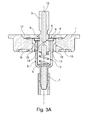
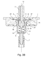
- the discharge element 3 is a tubular valve element which, as shown in the Fig. 3a and 3b a blind bore 12 having at least one adjoining the blind bore opening 11.
- the opening 11 extends in the embodiment radially through the wall of the dispensing element.
- the delivery element 3 has a guide section 13 which is supported on the compression spring 5 of the valve arrangement 2 and is guided axially movably within the accommodation space 6.
- the opening 11 is disposed above the guide portion 13 and opens into an annular groove 14.
- the delivery element 3 is depressed, the opening 11 is released and the pressurized product through the opening 11 and the blind bore 12th flows.
- the sealing ring 4 is expediently designed as an annular disc and consists of a polymer suitable for sealing purposes. Preference is given to elastomeric sealing materials, in particular natural rubber, synthetic rubber or thermoplastic elastomers.
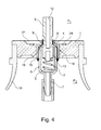
- the pressure p 1 on the outside of the valve assembly is greater than the pressure p 2 within the still unfilled aerosol container 16.
- the pressure p 1 builds up.
- the sealing ring 4 is supported on the underside by the discharge element 3 and seals the receiving space 6 from. Under the action of acting on the end face of the sealing ring 4 pressure p 1 there is an elastic deformation of the sealing ring 4, wherein a flow path between the end face of the sealing ring 4 and the receiving space 6 occlusive surface 8 is released.
- the propellant flows along the direction indicated by arrows flow path over the entire circumference of the sealing ring 4 radially and is passed through the immediately adjacent gas channels 15 into the interior of the aerosol container 16.
- the mounting opening of the receiving space 6 is accessible at the top of the valve disk 1 and the passage opening 9 is arranged for the discharge element 3 in a cover 17 which is fixed to the valve disk 1 and the mounting opening of the receiving space 6 closes.
- the gas channels 15 extend to a surface on the underside of the lid 17th
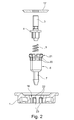
- the receiving space 6 and the valve plate 1 consist in the in the Fig. 1 to 3 illustrated embodiment of separate components, which preferably are made of plastic and can be manufactured as inexpensive injection molded parts.
- the valve disk 1 has an opening 18 for mounting the receiving space 6.
- the exploded view in Fig. 2 if one deduces that the component forming the receiving space 6 can be inserted into the opening 18 at the upper side of the valve disk 1. From the Fig. 1 and 2 is also apparent that the receiving space 6 has on its front side an annular seat surface 19 for the sealing ring 4 and outer longitudinal ribs 20.
- the longitudinal ribs 20 protrude beyond the seat surface 19 and grip the sealing ring 4 resting on the seat surface 19.
- the longitudinal ribs 20 are formed with a collar 21 which rests on a shoulder surface 22 within the opening 18 of the valve disk 1.
- the shoulder surface 22 consists of a plurality of ribs 23 which are arranged in the opening of the valve disk 1.
- the ribs 23 within the opening 18 of the receiving space 6 and formed on the outside of the receiving space 6 longitudinal ribs 20 correspond in terms of their support surface. The number of ribs and the distance between the ribs determine the rate of passage of the filling process.
- valve disk 1 and the cover 17 are made of plastic and are in the in Fig. 1 illustrated embodiment cohesively connected by a welded joint 24.
- the welded connection 24 can be produced in particular by a laser technique. Other welding methods with ultrasound, infrared and the like are also possible.
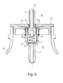
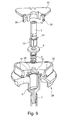
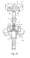
- the lid 17 and the valve plate 1 may alternatively be connected by a latching connection. Possible embodiments of such a locking connection are in the Fig. 9 and 10 shown.
- the valve disk 1 on its upper side a collar 25, in which the lid 17 is inserted without projection and is fixed by latching elements 26 on the inside of the collar 25.
- the locking connection is designed so that it is not solvable without destroying the object.
- the cover 17 comprises a collar 25 'formed on the upper side of the valve disk 1 on the outside and is fixed on the outside of the collar 25' by latching elements 26 '.
- the valve disk 1 and the receiving space 6 are formed together as a one-piece plastic injection molded part 27.
- the receiving space 6 is integrally connected as an integral part of the valve disk 1 with this.
- a recess 28 is formed with a seat surface 19 for the sealing ring 4.
- the gas channels 15 are arranged on the circumference of the recess 28 and extend to the bottom of the valve disk 1.
- the gas channels 15 together with a gap s, which is provided between the discharge element 3 and the discharge element surrounding the discharge opening 9, a flow path for pressure filling a closed with the valve assembly aerosol container 16.
- the flow path for a pressure filling is in Fig. 8 shown.
- the mounting opening of the receiving space 6 is accessible at the top of the valve disk 1, so that the complete assembly of the valve assembly at the top of the valve disk 1 can be performed.
- the Fig. 11a to 11c show a further falling under the invention design of the valve assembly, in which the receiving space 6 and the valve disk 1 consist of separate components and the assembly of the receiving space 6 takes place on the underside of the valve disk 1.
- the bottom designates that side of the valve disk 1 which is exposed to the pressure chamber of an aerosol container.
- the passage opening 9 is arranged for the discharge element 3 in the valve plate 1 and is formed on the underside of the valve disk 1, a projection 29 for fixing the receiving space 6 forming member.
- the receiving space 6 has on its front side an annular seat surface 19 for the sealing ring 4 and on the outside longitudinal ribs 20, which protrude on the seat surface 19 and surround the resting on the seat surface 19 sealing ring 4.
- the extension 29 and the receiving space 6 are materially connected in the embodiment by a weld 30.
- a weld 30 Preferably, the laser welding is used.
- the extension 29 and the receiving space 6 can also be connected, for example, by an adhesive connection, by a positive plug-in connection, a screw connection or latching connection.
Landscapes
- Chemical & Material Sciences (AREA)
- Dispersion Chemistry (AREA)
- Engineering & Computer Science (AREA)
- Mechanical Engineering (AREA)
- Containers And Packaging Bodies Having A Special Means To Remove Contents (AREA)
- Nozzles (AREA)
- Valve Housings (AREA)
- Lift Valve (AREA)
Abstract
Description
- Die Erfindung betrifft eine Ventilbaugruppe für Aerosolbehälter mit einem Ventilteller, einer Ventilanordnung, die mindestens ein Abgabeelement, einen Dichtungsring und eine Druckfeder umfasst, und mit einem Aufnahmeraum für die Ventilanordnung. Der Aufnahmeraum weist an seiner Oberseite eine Montageöffnung zum Einsetzen der Ventilanordnung auf. Die Montageöffnung des mit dem Ventilteller verbundenen Aufnahmeraums ist von einer Fläche verschlossen, die eine Durchtrittsöffnung für das Abgabeelement aufweist. Der Dichtungsring ist zwischen dieser Fläche und einer die Montageöffnung des Aufnahmeraums umgebenden ringförmigen Sitzfläche eingespannt und verschließt eine Öffnung des Abgabeelements, wenn das Abgabeelement unter der Wirkung der Druckfeder axial an dem Dichtungsring abgestützt ist. Bei dem Abgabeelement handelt es sich um einen Stem oder Aktuator. An seiner Unterseite weist der Aufnahmeraum einen Anschluss für ein Steigrohr oder andere spezifische Bauteile, die eine Fluidverbindung mit dem Innenraum des Aerosolbehälters herstellen, auf.
- Eine Ventilbaugruppe mit den beschriebenen Merkmalen ist aus
DE 38 07 156 A1 bekannt. Der Ventilteller der bekannten Ventilbaugruppe besteht aus Kunststoff und weist einen einstückig angeformten Aufnahmeraum auf, in den die Ventilanordnung eingesetzt wird. Der Aufnahmeraum wird anschließend durch eine Kunststoffkappe verschlossen, die mit dem Ventilteller durch Schweißen dicht verbunden wird. Der Dichtungsring greift in eine umfangsseitige Ringnut eines Stems ein, wenn der Stem unter der Wirkung der Druckfeder axial an dem Dichtungsring abgestützt ist. Oberhalb der Ringnut ist der Durchmesser des Stems größer als der Durchmesser eines fernerliegenden Abschnitts. Zur Druckbefüllung eines mit der Ventilbaugruppe verschlossenen Aerosolbehälters wird der Stem so weit in das Innere des Aufnahmeraums niedergedrückt, bis der mit einem geringen Durchmesser ausgebildete Abschnitt des Stems in die Durchtrittsöffnung der Kunststoffkappe eintaucht und sich dadurch ein ringförmiger Durchtrittsquerschnitt für das Treibmittel bildet. Das Fluid strömt durch einen Spalt zwischen der Dichtung und dem Stem in den Aufnahmeraum, durchströmt den Aufnahmeraum und gelangt von dort in den Innenraum des Aerosolbehälters. Da der Stem konstruktionsbedingt einen kleinen Durchmesser aufweist und innerhalb des Aufnahmeraums mit einem Schiebesitz geführt ist, ist der Strömungsweg mit einem merklichen Druckverlust behaftet, was sich nachteilig auf die Füllgeschwindigkeit auswirkt. - Vor diesem Hintergrund liegt der Erfindung die Aufgabe zugrunde, einen Strömungsweg innerhalb der Ventilbaugruppe vorzusehen, der bei einer Druckbefüllung einen großen Strömungsquerschnitt freigibt und nach der Druckbefüllung wieder dicht verschlossen ist.
- Gegenstand der Erfindung und Lösung dieser Aufgabe ist eine Ventilbaugruppe nach Anspruch 1.
- Erfindungsgemäß sind am äußeren Umfang des Aufnahmeraums Gaskanäle angeordnet, die sich von der Unterseite des Ventiltellers bis zum Umfang des Dichtungsrings erstrecken und zusammen mit einem Spalt, der zwischen dem Abgabeelement und der das Abgabeelement umgebenden Durchtrittsöffnung vorgesehen ist und an einer Stirnfläche des Dichtungsrings endet, einen Strömungsweg zur Druckbefüllung eines mit der Ventilbaugruppe verschlossenen Aerosolbehälters bilden. Bei der Druckbefüllung eines mit der Ventilbaugruppe verschlossenen Aerosolbehälters baut sich an der Stirnfläche des Dichtungsrings ein hoher Druck auf. Das Abgabeelement kann in der Position verbleiben, in der die Öffnung des Abgabeelements durch den Dichtungsring verschlossen ist. Da der Dichtungsring durch das Abgabeelement unterseitig abgestützt ist, dichtet der Dichtungsring den Aufnahmeraum weiterhin ab und verhindert, dass Treibmittel in den Aufnahmeraum eintritt. Dagegen nimmt die Dichtkraft zwischen der Stirnfläche des Dichtungsrings und der benachbarten Fläche infolge des auf die Stirnfläche des Dichtungsrings wirkenden Fülldrucks ab. Durch den auf die Stirnfläche des Dichtungsrings wirkenden Fülldruck verformt sich der Dichtungsring, wobei ein Strömungsweg zwischen der Stirnfläche des Dichtungsrings und der den Aufnahmeraum verschließenden Fläche freigegeben wird. Das Treibmittel strömt über den gesamten Umfang des Dichtungsrings radial ab und wird durch die unmittelbar anschließenden Gaskanäle in den Innenraum des Aerosolbehälters geleitet. Nach Beendigung des Füllvorgangs und Entlastung des von außen auf die Stirnfläche des Dichtungsrings wirkenden Drucks liegt der Dichtungsring wieder mit einer ausreichenden Dichtwirkung an der Abdeckfläche an. Zur Dichtwirkung trägt auch bei, dass der Innendruck des befüllten Aerosolbehälters auf den umfangsseitigen Rand des Dichtungsrings wirkt und eine Vorspannung des Dichtungsrings verstärkt. Damit ist der Strömungsweg, der für die Druckbefüllung genutzt worden ist, wieder betriebssicher verschlossen.
- Die beschriebene Befüllung betrifft insbesondere die Befüllung mit Treibmittel. In einem separaten Verfahrensschritt kann das Produkt zugeführt werden. Dazu wird das Abgabeelement nach unten gedrückt, so dass die Öffnung des Abgabeelements mit dem Aufnahmeraum der Ventilanordnung strömungstechnisch in Verbindung steht und die Befüllung mit dem Produkt durch das Abgabeelement und dessen Öffnung durch den Aufnahmeraum und ein unterseitig angeschlossenes Steigrohr erfolgen kann.
- Andere Arten der Befüllung sollen nicht ausgeschlossen sein. Die erfindungsgemäße Ventilanordnung ermöglicht beispielsweise auch eine Druckbefüllung mit Treibmittel, wenn das Abgabeelement nach unten gedrückt wird, bis die Öffnung des Abgabeventils mit dem Aufnahmeraum der Ventilanordnung strömungstechnisch in Verbindung steht. Der Strömungsweg des Treibmittels erstreckt sich hierbei sowohl über Spalt, Dichtungsring und Gaskanäle als auch über das Abgabeelement, dessen Öffnung durch den Aufnahmeraum und ein unterseitig angeschlossenes Steigrohr.
- Unter den Erfindungsgedanken fallen eine Mehrzahl konstruktiver Ausgestaltungen der Ventilbaugruppe, die nachfolgend erläutert werden. Gemäß einer ersten Ausführungsvariante ist die Montageöffnung des Aufnahmeraums an der Oberseite des Ventiltellers zugänglich und ist die Durchtrittsöffnung für das Abgabeelement in einem Deckel angeordnet, der an dem Ventilteller befestigt ist und die Montageöffnung des Aufnahmeraums verschließt. Der Aufnahmeraum der Ventilbaugruppe kann von der Ventiltelleraußenseite her mit der Ventilanordnung, d. h. zumindest einem Abgabeelement, einem Dichtungsring und der Druckfeder, bestückt werden. Anschließend muss der Aufnahmeraum nur noch durch Aufbringen des Deckels verschlossen werden. Die beschriebene konstruktive Ausführung der Erfindung ermöglicht eine einfache und vollautomatisierte Montage, die sich durch eine geringe Anzahl von Montageschritten auszeichnet. Die für eine Druckbefüllung eines mit der Ventilbaugruppe verschlossenen Aerosolbehälters vorgesehenen Gaskanäle erstrecken sich von der Unterseite des Ventiltellers bis zu einer Fläche des Deckels.
- Der Ventilteller und der Deckel bestehen vorzugsweise aus Kunststoff, wobei mehrere Möglichkeiten zur Verbindung des Ventiltellers und des Deckels in Betracht kommen. So kann der Deckel mit dem Ventilteller verschweißt oder verklebt werden. Alternativ können der Deckel und der Ventilteller durch eine Rastverbindung formschlüssig verbunden sein. Eine vorteilhafte konstruktive Ausgestaltung einer solchen Rastverbindung sieht vor, dass der Ventilteller an seiner Oberseite einen Kragen aufweist, in den der Deckel ohne Überstand einsetzbar ist, und dass der Deckel durch Rastelemente an der Innenseite des Kragens fixiert ist. Die konstruktive Ausgestaltung ermöglicht eine sehr einfache Montage, wobei sich eine Verbindung einstellt, die nicht zerstörungsfrei lösbar ist. Gemäß einer Ausführungsvariante umfasst der Deckel einen an der Oberseite des Ventiltellers angeformten Kragen und ist durch Rastelemente an der Außenseite des Kragens fixiert. Die aus einem Kragen und einem Deckel bestehende Anordnung zeichnet sich, unabhängig von der konkreten konstruktiven Ausgestaltung, durch eine hohe Formstabilität aus, was sich vorteilhaft auf die Funktion der Ventilbaugruppe auswirkt.
- Der Ventilteller und der Aufnahmeraum bestehen zweckmäßig aus Kunststoff und lassen sich kostengünstig als einstückiges Spritzgussteil herstellen, welches beide Funktionen vereint. Das Kunststoffspritzgussteil hat die Form eines Ventiltellers und einen angeformten Aufnahmeraum für die Ventilanordnung. Der Aufnahmeraum ist integraler Bestandteil des Ventiltellers und einstückig mit diesem verbunden. An der oberseitigen Stirnfläche des Ventiltellers ist bei dieser Ausführung eine Vertiefung mit einer Sitzfläche für den Dichtungsring eingeformt. Die Gaskanäle sind am Umfang der Vertiefung angeordnet und erstrecken sich bis zur Unterseite des Ventiltellers.
- Während der Ventilteller für viele Anwendungen standardisierte Abmessungen aufweisen kann, ist die Länge und der Durchmesser des Aufnahmeraums abhängig von der konstruktiven Ausführung der Ventilanordnung und der Gestaltung ihrer Ventilelemente. Daher kann es vorteilhaft sein, wenn der Aufnahmeraum und der Ventilteller aus separaten Bauteilen bestehen, die miteinander kombiniert werden können. Eine vorteilhafte Ausführung der Erfindung sieht vor, dass der Aufnahmeraum und der Ventilteller aus separaten Bauteilen bestehen, wobei der Ventilteller eine Öffnung zur Montage des Aufnahmeraums aufweist und wobei das den Aufnahmeraum bildende Bauteil an der Oberseite des Ventiltellers in die Öffnung einsetzbar ist. Bei dieser Ausführung lassen sich sämtliche Montageschritte, nämlich das Einsetzen des Aufnahmeraums in den Ventilteller, das Bestücken des Aufnahmeraums mit Ventilelementen und das Verschließen des Aufnahmeraums mit dem Deckel von einer Seite, nämlich an der Oberseite des Ventiltellers, ausführen. Dies vereinfacht in erheblichem Maße die Montage der Ventilbaugruppe.
- Das den Aufnahmeraum bildende separate Bauteil weist an seiner Stirnseite zweckmäßig eine ringförmige Sitzfläche für den Dichtungsring sowie außenseitige Längsrippen auf, wobei die Längsrippen an der Sitzfläche überstehen und den auf der Sitzfläche aufliegenden Dichtungsring einfassen. Die Längsrippen können dabei einen Kragen aufweisen, der auf einer Schulterfläche innerhalb der Öffnung des Ventiltellers aufliegt. Auch die Schulterfläche innerhalb der Öffnung des Ventiltellers besteht zweckmäßig aus einer Anordnung aus mehreren Rippen, wobei die Rippenbreite und der Rippenabstand auf die Längsrippen an der Außenseite des den Aufnahmeraum bildenden Bauteils abgestimmt sind. Der Ventilteller und das den Aufnahmeraum bildende Bauteil können kostengünstig als Kunststoffspritzgussteile gefertigt werden.
- Bei den zuvor beschriebenen Ausführungen der Erfindung ist der Aufnahmeraum für die Ventilanordnung stets durch einen Deckel verschlossen, der eine Öffnung für das Abgabeelement aufweist und an der Oberseite bzw. Außenseite des Ventiltellers befestigt ist. Eine zweite Konstruktionsvariante, die ebenfalls von dem Erfindungsgedanken umfasst sein soll, sieht vor, dass der Aufnahmeraum und der Ventilteller aus separaten Bauteilen bestehen, wobei die Durchtrittsöffnung für das Abgabeelement im Ventilteller angeordnet ist und wobei an der Unterseite des Ventiltellers ein Fortsatz zur Befestigung des den Aufnahmeraum bildenden Bauteils angeformt ist. Bei dieser konstruktiven Ausgestaltung entfällt ein Deckel. Der Aufnahmeraum muss zunächst mit der Ventilanordnung bestückt werden und kann dann als vorgefertigte Baugruppe an der Unterseite des Ventiltellers befestigt werden. Der zur Befestigung vorgesehene Fortsatz an der Unterseite des Ventiltellers ist vorzugsweise als Muffe ausgebildet, in die das den Aufnahmeraum bildende Bauteil einsetzbar ist. Vorzugsweise weist der Aufnahmeraum an seiner Stirnseite eine ringförmige Sitzfläche für den Dichtungsring sowie außenseitige Längsrippen auf, wobei die Längsrippen an der Sitzfläche überstehen und den auf der Sitzfläche aufliegenden Dichtungsring einfassen. Der Fortsatz und der Aufnahmeraum können mittels einer Schweißverbindung, einer Klebeverbindung, einer formschlüssigen Steckverbindung, einer Schraubverbindung oder Rastverbindung miteinander verbunden sein.
- Im Folgenden wird die Erfindung anhand einer lediglich ein Ausführungsbeispiel darstellenden Zeichnung erläutert. Es zeigen schematisch:
- Fig. 1
- eine Ventilbaugruppe für Aerosolbehälter in einer teilweise geschnittenen perspektivischen Darstellung,
- Fig. 2
- eine Explosionsdarstellung des in
Fig. 1 dargestellten Gegenstandes, - Fig. 3a, 3b
- Schnittdarstellungen der in
Fig. 1 dargestellten Ventilbaugruppe in zwei Schnittebenen, - Fig. 4
- den Strömungsweg durch die in
Fig. 1 dargestellte Ventilbaugruppe im Falle einer Druckbefüllung eines mit der Ventilbaugruppe verschlossenen Aerosolbehälters, - Fig. 5
- eine weitere Ausgestaltung der Ventilbaugruppe in einer perspektivischen und teilweise geschnittenen Darstellung,
- Fig. 6
- eine Explosionsdarstellung des in
Fig. 5 gezeigten Gegenstandes, - Fig. 7
- die Draufsicht auf einen Ventilteller der in
Fig. 5 dargestellten Ventilbaugruppe, - Fig. 8
- den Strömungsweg durch die in
Fig. 5 dargestellte Ventilbaugruppe im Falle einer Druckbefüllung eines mit der Ventilbaugruppe verschlossenen Aerosolbehälters, - Fig. 9, 10
- Ausführungsvarianten der Ventilbaugruppe,
- Fig. 11a bis 11c
- eine weitere Ausgestaltung der unter die Erfindung fallenden Ventilbaugruppe in mehreren Ansichten.
- Zum grundsätzlichen Aufbau der in mehreren Ausführungsbeispielen dargestellten Ventilbaugruppe gehören ein Ventilteller 1, eine Ventilanordnung 2, die mindestens ein Abgabeelement 3 in Form eines Stems, einen Dichtungsring 4 und eine Druckfeder 5 umfasst, sowie ein Aufnahmeraum 6 für die Ventilanordnung, der an seiner Unterseite einen Anschluss 7 für ein Steigrohr sowie an seiner Oberseite eine Montageöffnung zum Einsetzen der Ventilanordnung 2 aufweist. Die Montageöffnung des mit dem Ventilteller verbundenen Aufnahmeraums 6 ist von einer Fläche 8 verschlossen, die eine Durchtrittsöffnung 9 für das Abgabeelement 3 aufweist. Der Dichtungsring 4 ist zwischen dieser Fläche 8 und einer die Montageöffnung des Aufnahmeraums 6 umgebenden ringförmigen Sitzfläche 19 eingespannt und verschließt eine Öffnung 11 des Abgabeelements 3, wenn das Abgabeelement 3 unter der Wirkung der Druckfeder 5 axial an dem Dichtungsring 4 abgestützt ist. Die Öffnung 11 bildet eine Dosieröffnung.
- Das Abgabeelement 3 ist ein rohrförmiges Ventilelement, welches gemäß der Darstellung in den
Fig. 3a und3b eine Sackbohrung 12 mit mindestens einer an die Sackbohrung anschließenden Öffnung 11 aufweist. Die Öffnung 11 erstreckt sich im Ausführungsbeispiel radial durch die Wandung des Abgabeelements. Das Abgabeelement 3 weist einen Führungsabschnitt 13 auf, der an der Druckfeder 5 der Ventilanordnung 2 abgestützt ist und innerhalb des Aufnahmeraumes 6 axial beweglich geführt ist. Die Öffnung 11 ist oberhalb des Führungsabschnittes 13 angeordnet und mündet in einer Ringnut 14. In der in denFig. 3a und3b dargestellten Funktionsstellung greift der Dichtungsring 4 in die Ringnut 14 ein und verschließt die Öffnung 11. Zur Produktabgabe aus einem unter Druck stehenden Aerosolbehälter wird das Abgabeelement 3 niedergedrückt, wobei die Öffnung 11 freikommt und das unter Druck stehende Füllgut durch die Öffnung 11 und die Sackbohrung 12 ausströmt. - Der Dichtungsring 4 ist zweckmäßig als Ringscheibe ausgebildet und besteht aus einem für Dichtungszwecke geeigneten Polymer. Bevorzugt sind elastomere Dichtungswerkstoffe, insbesondere Naturkautschuk, Synthesekautschuk oder thermoplastische Elastomere.
- Aus einer vergleichenden Betrachtung der
Fig. 1 bis Fig. 3a /b geht hervor, dass am äußerem Umfang des Aufnahmeraums 6 Gaskanäle 15 angeordnet sind, die sich von der Unterseite des Ventiltellers 1 bis zum Umfang des Dichtungsrings 4 erstrecken. Diese Gaskanäle 15 bilden zusammen mit einem Spalt, der zwischen dem Abgabeelement 3 und der das Abgabeelement umgebenden Durchtrittsöffnung 9 vorgesehen ist, einen Strömungsweg zur Druckbefüllung eines mit der Ventilbaugruppe verschlossenen Aerosolbehälters 16. Der Strömungsweg ist in derFig. 4 dargestellt. Das Abgabeelement bleibt während der Druckbefüllung in der inFig. 4 dargestellten Position. Zwischen dem Abgabeelement 3 und der das Abgabeelement umgebenden Durchtrittsöffnung 9 ist ein Spalt s vorgesehen, der an einer Stirnfläche des Dichtungsrings 4 endet. Im Falle einer Druckbefüllung des Aerosolbehälters 16 ist der Druck p1 an der Außenseite der Ventilbaugruppe größer als der Druck p2 innerhalb des noch unbefüllten Aerosolbehälters 16. An der Stirnfläche des Dichtungsrings 4 baut sich der Druck p1 auf. Der Dichtungsring 4 ist unterseitig durch das Abgabeelement 3 abgestützt und dichtet den Aufnahmeraum 6 ab. Unter der Wirkung des auf die Stirnfläche des Dichtungsrings 4 wirkenden Drucks p1 kommt es zu einer elastischen Verformung des Dichtungsrings 4, wobei ein Strömungsweg zwischen der Stirnfläche des Dichtungsrings 4 und der den Aufnahmeraum 6 verschließenden Fläche 8 freigegeben wird. Das Treibmittel strömt entlang des durch Pfeile angedeuteten Strömungsweges über den gesamten Umfang des Dichtungsrings 4 radial ab und wird durch die unmittelbar anschließenden Gaskanäle 15 in den Innenraum des Aerosolbehälters 16 geleitet. Nach Beendigung des Füllvorgangs und Entlastung des von außen auf die Stirnfläche des Dichtungsrings 4 wirkenden Drucks liegt der Dichtungsring 4 wieder mit einer ausreichenden Dichtwirkung an der Fläche 8 an. Damit ist der Strömungsweg, der für die Druckbefüllung benutzt worden ist, wieder betriebssicher verschlossen. - In dem in den
Fig. 1 bis 3 dargestellten Ausführungsbeispiel ist die Montageöffnung des Aufnahmeraums 6 an der Oberseite des Ventiltellers 1 zugänglich und ist die Durchtrittsöffnung 9 für das Abgabeelement 3 in einem Deckel 17 angeordnet, der an dem Ventilteller 1 befestigt ist und die Montageöffnung des Aufnahmeraums 6 verschließt. Die Gaskanäle 15 erstrecken sich bis zu einer Fläche an der Unterseite des Deckels 17. - Der Aufnahmeraum 6 und der Ventilteller 1 bestehen in dem in den
Fig. 1 bis 3 dargestellten Ausführungsbeispiel aus separaten Bauteilen, die vorzugsweise aus Kunststoff bestehen und als kostengünstige Spritzgussteile gefertigt werden können. Der Ventilteller 1 weist eine Öffnung 18 zur Montage des Aufnahmeraums 6 auf. Der Explosionsdarstellung inFig. 2 entnimmt man, dass das den Aufnahmeraum 6 bildende Bauteil an der Oberseite des Ventiltellers 1 in die Öffnung 18 einsetzbar ist. Aus denFig. 1 und2 ist auch ersichtlich, dass der Aufnahmeraum 6 an seiner Stirnseite eine ringförmige Sitzfläche 19 für den Dichtungsring 4 sowie außenseitige Längsrippen 20 aufweist. Die Längsrippen 20 stehen an der Sitzfläche 19 über und fassen den auf der Sitzfläche 19 aufliegenden Dichtungsring 4 ein. Zur Abstützung des den Aufnahmeraum 6 bildenden Bauteils sind die Längsrippen 20 mit einem Kragen 21 ausgebildet, der auf einer Schulterfläche 22 innerhalb der Öffnung 18 des Ventiltellers 1 aufliegt. AusFig. 2 ist ersichtlich, dass die Schulterfläche 22 aus einer Mehrzahl von Rippen 23 besteht, die in der Öffnung des Ventiltellers 1 angeordnet sind. Die Rippen 23 innerhalb der Öffnung 18 des Aufnahmeraums 6 und die an der Außenseite des Aufnahmeraums 6 angeformten Längsrippen 20 korrespondieren hinsichtlich ihrer Auflagefläche. Die Anzahl der Rippen und der Abstand zwischen den Rippen bestimmen die Durchgangsrate des Befüllprozesses. - Der Ventilteller 1 und der Deckel 17 bestehen aus Kunststoff und sind in dem in
Fig. 1 dargestellten Ausführungsbeispiel stoffschlüssig durch eine Schweißverbindung 24 verbunden. Die Schweißverbindung 24 kann insbesondere durch eine Lasertechnik hergestellt werden. Andere Schweißverfahren mit Ultraschall, Infrarot und dergleichen sind ebenfalls möglich. - Der Deckel 17 und der Ventilteller 1 können alternativ auch durch eine Rastverbindung verbunden werden. Mögliche Ausführungen einer solchen Rastverbindung sind in den
Fig. 9 und10 dargestellt. Im Ausführungsbeispiel derFig. 9 weist der Ventilteller 1 an seiner Oberseite einen Kragen 25 auf, in den der Deckel 17 ohne Überstand eingesetzt und durch Rastelemente 26 an der Innenseite des Kragens 25 fixiert ist. Die Rastverbindung ist so ausgestaltet, dass sie ohne Zerstörung des Gegenstandes nicht lösbar ist. Gemäß der in Fig. 19 dargestellten Ausführungsvariante umfasst der Deckel 17 einen an der Oberseite des Ventiltellers 1 angeformten Kragen 25' außenseitig und ist durch Rastelemente 26' an der Außenseite des Kragens 25' fixiert. - Gemäß einer in den
Fig. 5 bis 7 dargestellten Ausgestaltung der Erfindung sind der Ventilteller 1 und der Aufnahmeraum 6 zusammen als einstückiges Kunststoffspritzgussteil 27 ausgebildet. Der Aufnahmeraum 6 ist als integraler Bestandteil des Ventiltellers 1 einstückig mit diesem verbunden. An der oberseitigen Stirnfläche des Ventiltellers 1 ist eine Vertiefung 28 mit einer Sitzfläche 19 für den Dichtungsring 4 eingeformt. Gemäß den Darstellungen in denFig. 5 bis 7 sind die Gaskanäle 15 am Umfang der Vertiefung 28 angeordnet und erstrecken sich bis zur Unterseite des Ventiltellers 1. Die Gaskanäle 15 bilden zusammen mit einem Spalt s, der zwischen dem Abgabeelement 3 und der das Abgabeelement umgebenden Durchtrittsöffnung 9 vorgesehen ist, einen Strömungsweg zur Druckbefüllung eines mit der Ventilbaugruppe verschlossenen Aerosolbehälters 16. Der Strömungsweg für eine Druckbefüllung ist inFig. 8 dargestellt. - Bei den zuvor beschriebenen Ausführungsbeispielen ist die Montageöffnung des Aufnahmeraums 6 an der Oberseite des Ventiltellers 1 zugänglich, so dass die komplette Montage der Ventilbaugruppe an der Oberseite des Ventiltellers 1 ausgeführt werden kann.
- Die
Fig. 11a bis 11c zeigen eine weitere unter die Erfindung fallende Gestaltung der Ventilbaugruppe, bei der der Aufnahmeraum 6 und der Ventilteller 1 aus separaten Bauteilen bestehen und die Montage des Aufnahmeraums 6 an der Unterseite des Ventiltellers 1 erfolgt. Die Unterseite bezeichnet dabei diejenige Seite des Ventiltellers 1, die dem Druckraum eines Aerosolbehälters ausgesetzt ist. Bei dem in denFig. 11a bis 11c dargestellten Ausführungsbeispiel ist die Durchtrittsöffnung 9 für das Abgabeelement 3 im Ventilteller 1 angeordnet und ist an der Unterseite des Ventiltellers 1 ein Fortsatz 29 zur Befestigung des den Aufnahmeraum 6 bildenden Bauteils angeformt. Der Aufnahmeraum 6 weist an seiner Stirnseite eine ringförmige Sitzfläche 19 für den Dichtungsring 4 sowie außenseitige Längsrippen 20 auf, die an der Sitzfläche 19 überstehen und den auf der Sitzfläche 19 aufliegenden Dichtungsring 4 einfassen. Der Fortsatz 29 und der Aufnahmeraum 6 sind im Ausführungsbeispiel durch eine Schweißnaht 30 stoffschlüssig verbunden. Vorzugsweise wird das Laserschweißen angewendet. Anstelle einer Schweißverbindung können der Fortsatz 29 und der Aufnahmeraum 6 auch beispielsweise durch eine Klebeverbindung, durch eine formschlüssige Steckverbindung, eine Schraubverbindung oder Rastverbindung verbunden sein.
Claims (17)
- Ventilbaugruppe für Aerosolbehälter miteinem Ventilteller (1),einer Ventilanordnung (2), die mindestens ein Abgabeelement (3), einen Dichtungsring (4) und eine Druckfeder (15) umfasst, undeinem Aufnahmeraum (6) für die Ventilanordnung (2),wobei der Aufnahmeraum (6) an seiner Oberseite eine Montageöffnung zum Einsetzen der Ventilanordnung (2) aufweist, wobei die Montageöffnung des mit dem Ventilteller (1) verbundenen Aufnahmeraums (6) von einer Fläche (8) verschlossen ist, die eine Durchtrittsöffnung (9) für das Abgabeelement (3) aufweist, und wobei der Dichtungsring (4) zwischen dieser Fläche (8) und einer die Montageöffnung des Aufnahmeraums (6) umgebenden ringförmigen Sitzfläche (19) eingespannt ist und eine Öffnung (18) des Abgabeelements (3) verschließt, wenn das Abgabeelement (3) unter der Wirkung der Druckfeder (5) axial an dem Dichtungsring (4) abgestützt ist, dadurch gekennzeichnet, dass am äußeren Umfang des Aufnahmeraums (6) Gaskanäle (15) angeordnet sind, die sich von der Unterseite des Ventiltellers (1) bis zum Umfang des Dichtungsrings (4) erstrecken, und dass zwischen dem Abgabeelement (3) und der das Abgabeelement umgebenden Durchtrittsöffnung (9) ein Spalt (s) vorgesehen ist, der an einer Stirnfläche des Dichtungsrings (4) endet, wobei der Spalt (s) und die Gaskanäle (15) einen Strömungsweg zur Druckbefüllung eines mit der Ventilbaugruppe verschlossenen Aerosolbehälters (16) bilden.
- Ventilbaugruppe nach Anspruch 1, dadurch gekennzeichnet, dass die Montageöffnung des Aufnahmeraums (6) an der Oberseite des Ventiltellers (1) zugänglich ist und dass die Durchtrittsöffnung (9) für das Abgabeelement (3) in einem Deckel (17) angeordnet ist, der an dem Ventilteller (1) befestigt ist und die Montageöffnung des Aufnahmeraums (6) verschließt.
- Ventilbaugruppe nach Anspruch 2, dadurch gekennzeichnet, dass die Gaskanäle (15) sich bis zu einer Fläche des Deckels (17) erstrecken.
- Ventilbaugruppe nach Anspruch 2 oder 3, dadurch gekennzeichnet, dass der Ventilteller (1) sowie der Deckel (17) aus Kunststoff bestehen und stoffschlüssig durch eine Schweißverbindung oder Klebeverbindung verbunden sind.
- Ventilbaugruppe nach Anspruch 2 oder 3, dadurch gekennzeichnet, dass der Ventilteller (1) sowie der Deckel (17) aus Kunststoff bestehen und durch eine Rastverbindung formschlüssig verbunden sind.
- Ventilbaugruppe nach Anspruch 5, dadurch gekennzeichnet, dass der Ventilteller (1) an seiner Oberseite einen Kragen (25) aufweist, in den der Deckel (17) ohne Überstand eingesetzt ist, und dass der Deckel (17) durch Rastelemente (26) an der Innenseite des Kragens (25) fixiert ist.
- Ventilbaugruppe nach Anspruch 5, dadurch gekennzeichnet, dass der Deckel (17) einen an der Oberseite des Ventiltellers (1) angeformten Kragen (25') außenseitig umfasst und durch Rastelemente (26') an der Außenseite des Kragens (25') fixiert ist.
- Ventilbaugruppe nach einem der Ansprüche 2 bis 7, dadurch gekennzeichnet, dass der Ventilteller (1) und der Aufnahmeraum (6) zusammen als einstückiges Kunststoffspritzgussteil ausgebildet sind, wobei an der oberseitigen Stirnfläche des Ventiltellers (1) eine Vertiefung (28) mit einer Sitzfläche (19) für den Dichtungsring (4) eingeformt ist und wobei die Gaskanäle (15) am Umfang der Vertiefung (28) angeordnet sind und sich bis zur Unterseite des Ventiltellers (1) erstrecken.
- Ventilbaugruppe nach einem der Ansprüche 2 bis 7, dadurch gekennzeichnet, dass der Aufnahmeraum (6) und der Ventilteller (1) aus separaten Bauteilen bestehen, wobei der Ventilteller (1) eine Öffnung (18) zur Montage des Aufnahmeraums (6) aufweist und wobei das den Aufnahmeraum (6) bildende Bauteil an der Oberseite des Ventiltellers (1) in die Öffnung (18) einsetzbar ist.
- Ventilbaugruppe nach Anspruch 9, dadurch gekennzeichnet, dass der Aufnahmeraum (6) an seiner Stirnseite eine ringförmige Sitzfläche (19) für den Dichtungsring (4) sowie außenseitige Längsrippen (20) aufweist, wobei die Längsrippen (20) an der Sitzfläche (19) überstehen und den auf der Sitzfläche (19) aufliegenden Dichtungsring(4) einfassen.
- Ventilbaugruppe nach Anspruch 10, dadurch gekennzeichnet, dass die Längsrippen (20) einen Kragen (21) aufweisen, der auf einer Schulterfläche (22) innerhalb der Öffnung des Ventiltellers (1) aufliegt.
- Ventilbaugruppe nach Anspruch 11, dadurch gekennzeichnet, dass die Schulterfläche (22) aus einer Anzahl von Rippen (23) besteht.
- Ventilbaugruppe nach einem der Ansprüche 9 bis 12, dadurch gekennzeichnet, dass der Ventilteller (1) und der Aufnahmeraum (6) separat gefertigte Kunststoffspritzgussteile sind.
- Ventilbaugruppe nach Anspruch 1, dadurch gekennzeichnet, dass der Aufnahmeraum (6) und der Ventilteller (1) aus separaten Bauteilen bestehen, wobei die Durchtrittsöffnung (9) für das Abgabeelement (3) im Ventilteller (1) angeordnet ist und wobei an der Unterseite des Ventiltellers (1) ein Fortsatz (29) zur Befestigung des den Aufnahmeraum (6) bildenden Bauteils angeformt ist.
- Ventilbaugruppe nach Anspruch 14, dadurch gekennzeichnet, dass der Fortsatz (29) als Muffe ausgebildet ist, in die das den Aufnahmeraum (6) bildende Bauteil einsetzbar ist.
- Ventilbaugruppe nach Anspruch 15, dadurch gekennzeichnet, dass das den Aufnahmeraum (6) bildende Bauteil an seiner Stirnseite eine ringförmige Sitzfläche (19) für den Dichtungsring (4) sowie außenseitige Längsrippen (20) aufweist, wobei die Längsrippen (20) an der Sitzfläche (19) überstehen und den auf der Sitzfläche (19) aufliegenden Dichtungsring (4) einfassen.
- Ventilbaugruppe nach einem der Ansprüche 14 bis 16, dadurch gekennzeichnet, dass der Fortsatz (29) und der Aufnahmeraum (6) mittels einer Schweißverbindung, Klebeverbindung, formschlüssigen Steckverbindung, Schraubverbindung oder Rastverbindung verbunden sind.
Applications Claiming Priority (1)
| Application Number | Priority Date | Filing Date | Title |
|---|---|---|---|
| DE102014100280.6A DE102014100280A1 (de) | 2014-01-13 | 2014-01-13 | Ventilbaugruppe für Aerosolbehälter |
Publications (2)
| Publication Number | Publication Date |
|---|---|
| EP2894114A1 true EP2894114A1 (de) | 2015-07-15 |
| EP2894114B1 EP2894114B1 (de) | 2019-02-13 |
Family
ID=52338907
Family Applications (1)
| Application Number | Title | Priority Date | Filing Date |
|---|---|---|---|
| EP14200241.9A Active EP2894114B1 (de) | 2014-01-13 | 2014-12-23 | Ventilbaugruppe für Aerosolbehälter |
Country Status (12)
| Country | Link |
|---|---|
| US (1) | US9598227B2 (de) |
| EP (1) | EP2894114B1 (de) |
| JP (1) | JP6045614B2 (de) |
| CN (1) | CN104925396B (de) |
| AR (1) | AR099076A1 (de) |
| BR (1) | BR102015000658B1 (de) |
| CA (1) | CA2877638C (de) |
| DE (1) | DE102014100280A1 (de) |
| ES (1) | ES2725624T3 (de) |
| IN (1) | IN2015DE00084A (de) |
| MX (1) | MX354075B (de) |
| RU (1) | RU2598576C2 (de) |
Cited By (1)
| Publication number | Priority date | Publication date | Assignee | Title |
|---|---|---|---|---|
| DE102018003741A1 (de) | 2018-03-16 | 2019-09-19 | Aptar Dortmund Gmbh | Ventilanordnung und Abgabevorrichtung |
Families Citing this family (12)
| Publication number | Priority date | Publication date | Assignee | Title |
|---|---|---|---|---|
| WO2015083642A1 (ja) * | 2013-12-03 | 2015-06-11 | 株式会社三谷バルブ | エアゾールハウジング機構およびこのエアゾールハウジング機構を備えたエアゾール式製品 |
| FR3037571B1 (fr) * | 2015-06-16 | 2019-11-22 | Lindal France | Procede pour fabriquer une valve d'aerosol et valve d'aerosol |
| FR3048236B1 (fr) * | 2016-02-29 | 2019-07-12 | Albea Le Treport | Systeme de distribution de produit pour flacon |
| US10501258B2 (en) * | 2017-05-26 | 2019-12-10 | The Procter & Gamble Company | Aerosol dispenser having annular seals and aerosol container therefor |
| US10836562B2 (en) * | 2018-04-16 | 2020-11-17 | The Procter & Gamble Company | Crystallized plastic valve for an aerosol dispenser and housing therefor |
| FR3099144B1 (fr) | 2019-07-24 | 2022-01-07 | Lindal France | Valve pour récipient sous pression |
| CN118323654A (zh) | 2019-07-24 | 2024-07-12 | 林达尔法国两合公司 | 用于压力容器的阀杯 |
| EP4003877B1 (de) * | 2019-07-26 | 2024-05-08 | The Procter & Gamble Company | Ventilanordnung |
| EP4003873B1 (de) | 2019-07-26 | 2024-03-06 | The Procter & Gamble Company | Ventilanordnung |
| CN114174196B (zh) | 2019-07-26 | 2023-08-01 | 宝洁公司 | 用于分配器的阀组件 |
| CN114127450B (zh) * | 2019-07-26 | 2024-08-23 | 宝洁公司 | 用于分配器的阀组件 |
| CN111140666A (zh) * | 2020-01-17 | 2020-05-12 | 中山市联昌喷雾泵有限公司 | 一种阀及塑料罐盖的罐 |
Citations (7)
| Publication number | Priority date | Publication date | Assignee | Title |
|---|---|---|---|---|
| US2890817A (en) * | 1956-09-06 | 1959-06-16 | Karl Kiefer Machine Company | Valve means for pressurized container |
| BE674080A (de) * | 1964-08-03 | 1966-06-20 | ||
| FR2313617A1 (fr) * | 1975-06-07 | 1976-12-31 | Aerosol Inventions Dev | Valves pour distributeurs sous pression |
| DE2556163A1 (de) * | 1975-12-13 | 1977-06-23 | Praezisions Ventil Gmbh | Ventil fuer druckgaspackungen |
| DE3807156A1 (de) | 1988-03-04 | 1989-09-14 | Perfect Ventil Gmbh | Aerosolbehaelter |
| JPH09240761A (ja) * | 1996-03-08 | 1997-09-16 | Mitani Valve:Kk | 包装容器用バルブ構造 |
| JP2005271921A (ja) * | 2004-03-22 | 2005-10-06 | Mitani Valve Co Ltd | エアゾール容器用のハウジングおよびエアゾール式製品 |
Family Cites Families (10)
| Publication number | Priority date | Publication date | Assignee | Title |
|---|---|---|---|---|
| JPS4330259Y1 (de) * | 1965-06-24 | 1968-12-11 | ||
| US3669316A (en) * | 1970-07-27 | 1972-06-13 | Diamond Int Corp | Cartridge valve dispenser with pressure regulating valve |
| IT1012693B (it) * | 1974-05-21 | 1977-03-10 | Coster Tecnologie Speciali Spa | Valvola per contenituri di aerosol |
| FR2441778A1 (fr) * | 1978-11-17 | 1980-06-13 | Aerosol Inventions Dev | Ensemble de distribution et remplissage pour recipient aerosol |
| JPH0446836Y2 (de) * | 1986-07-31 | 1992-11-05 | ||
| JPH09193981A (ja) * | 1996-01-18 | 1997-07-29 | Seiichi Kitabayashi | 懸垂袋を懸垂させた全部材が合成樹脂製のエアゾールバルブ |
| DE20002335U1 (de) * | 2000-02-10 | 2000-04-06 | Aerosol Technik Lindal Gmbh, 23843 Bad Oldesloe | Ventil für die Entnahme von flüssigem Medium aus einem druckdichten Behälter |
| US6394321B1 (en) * | 2001-12-20 | 2002-05-28 | Precision Valve Corporation | Aerosol powder valve |
| WO2007107174A1 (de) * | 2006-03-21 | 2007-09-27 | Coster Tecnologie Speciali S.P.A. | Baueinheit für ein abgabeventil für die abgabe von unter druck stehenden flüssigkeiten, und behälter mit einer derartigen baueinheit |
| GB0702398D0 (en) * | 2007-02-08 | 2007-03-21 | Leafgreen Ltd | A valve for a pressurised dispenser and a pressurised dispenser containing such a valve |
-
2014
- 2014-01-13 DE DE102014100280.6A patent/DE102014100280A1/de not_active Withdrawn
- 2014-12-23 EP EP14200241.9A patent/EP2894114B1/de active Active
- 2014-12-23 ES ES14200241T patent/ES2725624T3/es active Active
-
2015
- 2015-01-07 US US14/591,030 patent/US9598227B2/en active Active
- 2015-01-09 MX MX2015000351A patent/MX354075B/es active IP Right Grant
- 2015-01-09 JP JP2015003075A patent/JP6045614B2/ja active Active
- 2015-01-10 IN IN84DE2015 patent/IN2015DE00084A/en unknown
- 2015-01-12 RU RU2015100267/12A patent/RU2598576C2/ru active
- 2015-01-12 AR ARP150100071A patent/AR099076A1/es active IP Right Grant
- 2015-01-12 BR BR102015000658-6A patent/BR102015000658B1/pt active IP Right Grant
- 2015-01-12 CA CA2877638A patent/CA2877638C/en active Active
- 2015-01-13 CN CN201510107385.6A patent/CN104925396B/zh active Active
Patent Citations (7)
| Publication number | Priority date | Publication date | Assignee | Title |
|---|---|---|---|---|
| US2890817A (en) * | 1956-09-06 | 1959-06-16 | Karl Kiefer Machine Company | Valve means for pressurized container |
| BE674080A (de) * | 1964-08-03 | 1966-06-20 | ||
| FR2313617A1 (fr) * | 1975-06-07 | 1976-12-31 | Aerosol Inventions Dev | Valves pour distributeurs sous pression |
| DE2556163A1 (de) * | 1975-12-13 | 1977-06-23 | Praezisions Ventil Gmbh | Ventil fuer druckgaspackungen |
| DE3807156A1 (de) | 1988-03-04 | 1989-09-14 | Perfect Ventil Gmbh | Aerosolbehaelter |
| JPH09240761A (ja) * | 1996-03-08 | 1997-09-16 | Mitani Valve:Kk | 包装容器用バルブ構造 |
| JP2005271921A (ja) * | 2004-03-22 | 2005-10-06 | Mitani Valve Co Ltd | エアゾール容器用のハウジングおよびエアゾール式製品 |
Cited By (9)
| Publication number | Priority date | Publication date | Assignee | Title |
|---|---|---|---|---|
| DE102018003741A1 (de) | 2018-03-16 | 2019-09-19 | Aptar Dortmund Gmbh | Ventilanordnung und Abgabevorrichtung |
| WO2019174809A1 (de) | 2018-03-16 | 2019-09-19 | Aptar Dortmund Gmbh | Ventilanordnung und abgabgevorrichtung |
| CN111801284A (zh) * | 2018-03-16 | 2020-10-20 | 阿普塔多特蒙德有限公司 | 阀布置结构和分配设备 |
| DE102018003741B4 (de) | 2018-03-16 | 2021-08-26 | Aptar Dortmund Gmbh | Abgabevorrichtung mit reibverschweißtem Ventilteller |
| US11299338B2 (en) | 2018-03-16 | 2022-04-12 | Aptar Dortmund Gmbh | Valve arrangement and dispensing apparatus |
| CN111801284B (zh) * | 2018-03-16 | 2023-03-10 | 阿普塔多特蒙德有限公司 | 阀布置结构和分配设备 |
| CN116331670A (zh) * | 2018-03-16 | 2023-06-27 | 阿普塔多特蒙德有限公司 | 分配设备及其生产方法 |
| US11845605B2 (en) | 2018-03-16 | 2023-12-19 | Aptar Dortmund Gmbh | Valve arrangement and dispensing apparatus |
| EP4520509A2 (de) | 2018-03-16 | 2025-03-12 | Aptar Dortmund GmbH | Ventilanordnung und abgabevorrichtung |
Also Published As
| Publication number | Publication date |
|---|---|
| AR099076A1 (es) | 2016-06-29 |
| RU2015100267A (ru) | 2016-07-27 |
| JP2015131683A (ja) | 2015-07-23 |
| RU2598576C2 (ru) | 2016-09-27 |
| ES2725624T3 (es) | 2019-09-25 |
| CA2877638A1 (en) | 2015-07-13 |
| DE102014100280A1 (de) | 2015-07-16 |
| CN104925396A (zh) | 2015-09-23 |
| US20150197392A1 (en) | 2015-07-16 |
| US9598227B2 (en) | 2017-03-21 |
| BR102015000658B1 (pt) | 2021-03-23 |
| CN104925396B (zh) | 2017-09-01 |
| EP2894114B1 (de) | 2019-02-13 |
| IN2015DE00084A (de) | 2015-07-17 |
| BR102015000658A2 (pt) | 2016-07-05 |
| MX354075B (es) | 2018-02-12 |
| MX2015000351A (es) | 2016-04-26 |
| JP6045614B2 (ja) | 2016-12-14 |
| CA2877638C (en) | 2017-05-16 |
Similar Documents
| Publication | Publication Date | Title |
|---|---|---|
| EP2894114B1 (de) | Ventilbaugruppe für Aerosolbehälter | |
| DE69629850T2 (de) | Pumpe mit zerbrechlicher Membranabdichtung | |
| EP1744833B1 (de) | Fliessbecher mit lüftung für eine farbspritzpistole | |
| EP3116659B1 (de) | Austragkopf für einen spender, spender mit austragkopf und verfahren zur herstellung eines austragkopfes | |
| DE102018003741B4 (de) | Abgabevorrichtung mit reibverschweißtem Ventilteller | |
| DE102008019224A1 (de) | Ventilanordnung für einen unter Druck stehenden Fluidbehälter | |
| EP0048421A1 (de) | Spender | |
| EP0217013B1 (de) | Längenverstellbare Gasfeder | |
| DE29508658U1 (de) | Eintreibgerät für Befestigungsmittel | |
| WO1992006019A1 (de) | Einweg-druckbehälter, insbesondere als nachfüllbehälter für kälte- und klimaanlagen | |
| EP2539244A2 (de) | Verpackung | |
| WO2018189008A1 (de) | Filtervorrichtung | |
| EP3747550A1 (de) | Vorrichtung zur aufbewahrung und abgabe einer flüssigen oder pastösen masse | |
| WO2004056660A2 (de) | Druckdose zum mischen und ausbringen zweikomponentiger werkstoffe | |
| DE102017122488A1 (de) | Applikator mit einer Dichtungsmembran | |
| EP1410817A1 (de) | Spritzenzylinder | |
| EP2654967B1 (de) | Austragvorrichtung für eine flüssigkeit | |
| WO2016055238A1 (de) | Ablaufstutzen | |
| DE3420756C2 (de) | ||
| EP3105170B1 (de) | Zapfkopf für ein getränkefass | |
| DE102008020722B3 (de) | Druckluftstecker mit Rückflussdrosselung bestehend aus Metallsteckerteil und Kunststofftülle | |
| DE9017784U1 (de) | Vorrichtung zum intermittierenden Auftragen eines Fluids auf ein Substrat | |
| EP1588770B1 (de) | Austragkopf für eine Dosiereinrichtung | |
| DE19633266A1 (de) | Vorrichtung zum Auftragen eines viskosen Mediums | |
| DE102011078962A1 (de) | Eisdruckschutzvorrichtung |
Legal Events
| Date | Code | Title | Description |
|---|---|---|---|
| PUAI | Public reference made under article 153(3) epc to a published international application that has entered the european phase |
Free format text: ORIGINAL CODE: 0009012 |
|
| 17P | Request for examination filed |
Effective date: 20150223 |
|
| AK | Designated contracting states |
Kind code of ref document: A1 Designated state(s): AL AT BE BG CH CY CZ DE DK EE ES FI FR GB GR HR HU IE IS IT LI LT LU LV MC MK MT NL NO PL PT RO RS SE SI SK SM TR |
|
| AX | Request for extension of the european patent |
Extension state: BA ME |
|
| RBV | Designated contracting states (corrected) |
Designated state(s): AL AT BE BG CH CY CZ DE DK EE ES FI FR GB GR HR HU IE IS IT LI LT LU LV MC MK MT NL NO PL PT RO RS SE SI SK SM TR |
|
| REG | Reference to a national code |
Ref country code: DE Ref legal event code: R079 Ref document number: 502014010802 Country of ref document: DE Free format text: PREVIOUS MAIN CLASS: B65D0083420000 Ipc: B65D0083480000 |
|
| GRAP | Despatch of communication of intention to grant a patent |
Free format text: ORIGINAL CODE: EPIDOSNIGR1 |
|
| STAA | Information on the status of an ep patent application or granted ep patent |
Free format text: STATUS: GRANT OF PATENT IS INTENDED |
|
| RIC1 | Information provided on ipc code assigned before grant |
Ipc: B65D 83/42 20060101ALI20180720BHEP Ipc: B65D 83/48 20060101AFI20180720BHEP |
|
| INTG | Intention to grant announced |
Effective date: 20180823 |
|
| GRAS | Grant fee paid |
Free format text: ORIGINAL CODE: EPIDOSNIGR3 |
|
| GRAA | (expected) grant |
Free format text: ORIGINAL CODE: 0009210 |
|
| STAA | Information on the status of an ep patent application or granted ep patent |
Free format text: STATUS: THE PATENT HAS BEEN GRANTED |
|
| AK | Designated contracting states |
Kind code of ref document: B1 Designated state(s): AL AT BE BG CH CY CZ DE DK EE ES FI FR GB GR HR HU IE IS IT LI LT LU LV MC MK MT NL NO PL PT RO RS SE SI SK SM TR |
|
| REG | Reference to a national code |
Ref country code: GB Ref legal event code: FG4D Free format text: NOT ENGLISH |
|
| REG | Reference to a national code |
Ref country code: CH Ref legal event code: EP Ref country code: AT Ref legal event code: REF Ref document number: 1096069 Country of ref document: AT Kind code of ref document: T Effective date: 20190215 |
|
| REG | Reference to a national code |
Ref country code: IE Ref legal event code: FG4D Free format text: LANGUAGE OF EP DOCUMENT: GERMAN |
|
| REG | Reference to a national code |
Ref country code: DE Ref legal event code: R096 Ref document number: 502014010802 Country of ref document: DE |
|
| REG | Reference to a national code |
Ref country code: NL Ref legal event code: FP |
|
| REG | Reference to a national code |
Ref country code: LT Ref legal event code: MG4D |
|
| PG25 | Lapsed in a contracting state [announced via postgrant information from national office to epo] |
Ref country code: FI Free format text: LAPSE BECAUSE OF FAILURE TO SUBMIT A TRANSLATION OF THE DESCRIPTION OR TO PAY THE FEE WITHIN THE PRESCRIBED TIME-LIMIT Effective date: 20190213 Ref country code: PT Free format text: LAPSE BECAUSE OF FAILURE TO SUBMIT A TRANSLATION OF THE DESCRIPTION OR TO PAY THE FEE WITHIN THE PRESCRIBED TIME-LIMIT Effective date: 20190613 Ref country code: NO Free format text: LAPSE BECAUSE OF FAILURE TO SUBMIT A TRANSLATION OF THE DESCRIPTION OR TO PAY THE FEE WITHIN THE PRESCRIBED TIME-LIMIT Effective date: 20190513 Ref country code: SE Free format text: LAPSE BECAUSE OF FAILURE TO SUBMIT A TRANSLATION OF THE DESCRIPTION OR TO PAY THE FEE WITHIN THE PRESCRIBED TIME-LIMIT Effective date: 20190213 Ref country code: LT Free format text: LAPSE BECAUSE OF FAILURE TO SUBMIT A TRANSLATION OF THE DESCRIPTION OR TO PAY THE FEE WITHIN THE PRESCRIBED TIME-LIMIT Effective date: 20190213 |
|
| PG25 | Lapsed in a contracting state [announced via postgrant information from national office to epo] |
Ref country code: LV Free format text: LAPSE BECAUSE OF FAILURE TO SUBMIT A TRANSLATION OF THE DESCRIPTION OR TO PAY THE FEE WITHIN THE PRESCRIBED TIME-LIMIT Effective date: 20190213 Ref country code: RS Free format text: LAPSE BECAUSE OF FAILURE TO SUBMIT A TRANSLATION OF THE DESCRIPTION OR TO PAY THE FEE WITHIN THE PRESCRIBED TIME-LIMIT Effective date: 20190213 Ref country code: HR Free format text: LAPSE BECAUSE OF FAILURE TO SUBMIT A TRANSLATION OF THE DESCRIPTION OR TO PAY THE FEE WITHIN THE PRESCRIBED TIME-LIMIT Effective date: 20190213 Ref country code: IS Free format text: LAPSE BECAUSE OF FAILURE TO SUBMIT A TRANSLATION OF THE DESCRIPTION OR TO PAY THE FEE WITHIN THE PRESCRIBED TIME-LIMIT Effective date: 20190613 Ref country code: BG Free format text: LAPSE BECAUSE OF FAILURE TO SUBMIT A TRANSLATION OF THE DESCRIPTION OR TO PAY THE FEE WITHIN THE PRESCRIBED TIME-LIMIT Effective date: 20190513 Ref country code: GR Free format text: LAPSE BECAUSE OF FAILURE TO SUBMIT A TRANSLATION OF THE DESCRIPTION OR TO PAY THE FEE WITHIN THE PRESCRIBED TIME-LIMIT Effective date: 20190514 |
|
| REG | Reference to a national code |
Ref country code: ES Ref legal event code: FG2A Ref document number: 2725624 Country of ref document: ES Kind code of ref document: T3 Effective date: 20190925 |
|
| PG25 | Lapsed in a contracting state [announced via postgrant information from national office to epo] |
Ref country code: DK Free format text: LAPSE BECAUSE OF FAILURE TO SUBMIT A TRANSLATION OF THE DESCRIPTION OR TO PAY THE FEE WITHIN THE PRESCRIBED TIME-LIMIT Effective date: 20190213 Ref country code: EE Free format text: LAPSE BECAUSE OF FAILURE TO SUBMIT A TRANSLATION OF THE DESCRIPTION OR TO PAY THE FEE WITHIN THE PRESCRIBED TIME-LIMIT Effective date: 20190213 Ref country code: CZ Free format text: LAPSE BECAUSE OF FAILURE TO SUBMIT A TRANSLATION OF THE DESCRIPTION OR TO PAY THE FEE WITHIN THE PRESCRIBED TIME-LIMIT Effective date: 20190213 Ref country code: SK Free format text: LAPSE BECAUSE OF FAILURE TO SUBMIT A TRANSLATION OF THE DESCRIPTION OR TO PAY THE FEE WITHIN THE PRESCRIBED TIME-LIMIT Effective date: 20190213 Ref country code: RO Free format text: LAPSE BECAUSE OF FAILURE TO SUBMIT A TRANSLATION OF THE DESCRIPTION OR TO PAY THE FEE WITHIN THE PRESCRIBED TIME-LIMIT Effective date: 20190213 Ref country code: AL Free format text: LAPSE BECAUSE OF FAILURE TO SUBMIT A TRANSLATION OF THE DESCRIPTION OR TO PAY THE FEE WITHIN THE PRESCRIBED TIME-LIMIT Effective date: 20190213 |
|
| REG | Reference to a national code |
Ref country code: DE Ref legal event code: R097 Ref document number: 502014010802 Country of ref document: DE |
|
| PG25 | Lapsed in a contracting state [announced via postgrant information from national office to epo] |
Ref country code: PL Free format text: LAPSE BECAUSE OF FAILURE TO SUBMIT A TRANSLATION OF THE DESCRIPTION OR TO PAY THE FEE WITHIN THE PRESCRIBED TIME-LIMIT Effective date: 20190213 Ref country code: SM Free format text: LAPSE BECAUSE OF FAILURE TO SUBMIT A TRANSLATION OF THE DESCRIPTION OR TO PAY THE FEE WITHIN THE PRESCRIBED TIME-LIMIT Effective date: 20190213 |
|
| PLBE | No opposition filed within time limit |
Free format text: ORIGINAL CODE: 0009261 |
|
| STAA | Information on the status of an ep patent application or granted ep patent |
Free format text: STATUS: NO OPPOSITION FILED WITHIN TIME LIMIT |
|
| 26N | No opposition filed |
Effective date: 20191114 |
|
| PG25 | Lapsed in a contracting state [announced via postgrant information from national office to epo] |
Ref country code: SI Free format text: LAPSE BECAUSE OF FAILURE TO SUBMIT A TRANSLATION OF THE DESCRIPTION OR TO PAY THE FEE WITHIN THE PRESCRIBED TIME-LIMIT Effective date: 20190213 |
|
| PG25 | Lapsed in a contracting state [announced via postgrant information from national office to epo] |
Ref country code: TR Free format text: LAPSE BECAUSE OF FAILURE TO SUBMIT A TRANSLATION OF THE DESCRIPTION OR TO PAY THE FEE WITHIN THE PRESCRIBED TIME-LIMIT Effective date: 20190213 |
|
| REG | Reference to a national code |
Ref country code: CH Ref legal event code: PL |
|
| REG | Reference to a national code |
Ref country code: BE Ref legal event code: MM Effective date: 20191231 |
|
| PG25 | Lapsed in a contracting state [announced via postgrant information from national office to epo] |
Ref country code: MC Free format text: LAPSE BECAUSE OF FAILURE TO SUBMIT A TRANSLATION OF THE DESCRIPTION OR TO PAY THE FEE WITHIN THE PRESCRIBED TIME-LIMIT Effective date: 20190213 |
|
| PG25 | Lapsed in a contracting state [announced via postgrant information from national office to epo] |
Ref country code: LU Free format text: LAPSE BECAUSE OF NON-PAYMENT OF DUE FEES Effective date: 20191223 Ref country code: IE Free format text: LAPSE BECAUSE OF NON-PAYMENT OF DUE FEES Effective date: 20191223 |
|
| PG25 | Lapsed in a contracting state [announced via postgrant information from national office to epo] |
Ref country code: BE Free format text: LAPSE BECAUSE OF NON-PAYMENT OF DUE FEES Effective date: 20191231 Ref country code: LI Free format text: LAPSE BECAUSE OF NON-PAYMENT OF DUE FEES Effective date: 20191231 Ref country code: CH Free format text: LAPSE BECAUSE OF NON-PAYMENT OF DUE FEES Effective date: 20191231 |
|
| REG | Reference to a national code |
Ref country code: AT Ref legal event code: MM01 Ref document number: 1096069 Country of ref document: AT Kind code of ref document: T Effective date: 20191223 |
|
| PG25 | Lapsed in a contracting state [announced via postgrant information from national office to epo] |
Ref country code: CY Free format text: LAPSE BECAUSE OF FAILURE TO SUBMIT A TRANSLATION OF THE DESCRIPTION OR TO PAY THE FEE WITHIN THE PRESCRIBED TIME-LIMIT Effective date: 20190213 Ref country code: AT Free format text: LAPSE BECAUSE OF NON-PAYMENT OF DUE FEES Effective date: 20191223 |
|
| PG25 | Lapsed in a contracting state [announced via postgrant information from national office to epo] |
Ref country code: HU Free format text: LAPSE BECAUSE OF FAILURE TO SUBMIT A TRANSLATION OF THE DESCRIPTION OR TO PAY THE FEE WITHIN THE PRESCRIBED TIME-LIMIT; INVALID AB INITIO Effective date: 20141223 Ref country code: MT Free format text: LAPSE BECAUSE OF FAILURE TO SUBMIT A TRANSLATION OF THE DESCRIPTION OR TO PAY THE FEE WITHIN THE PRESCRIBED TIME-LIMIT Effective date: 20190213 |
|
| PG25 | Lapsed in a contracting state [announced via postgrant information from national office to epo] |
Ref country code: MK Free format text: LAPSE BECAUSE OF FAILURE TO SUBMIT A TRANSLATION OF THE DESCRIPTION OR TO PAY THE FEE WITHIN THE PRESCRIBED TIME-LIMIT Effective date: 20190213 |
|
| PGFP | Annual fee paid to national office [announced via postgrant information from national office to epo] |
Ref country code: DE Payment date: 20251120 Year of fee payment: 12 |
|
| PGFP | Annual fee paid to national office [announced via postgrant information from national office to epo] |
Ref country code: GB Payment date: 20251219 Year of fee payment: 12 |
|
| PGFP | Annual fee paid to national office [announced via postgrant information from national office to epo] |
Ref country code: IT Payment date: 20251223 Year of fee payment: 12 |
|
| PGFP | Annual fee paid to national office [announced via postgrant information from national office to epo] |
Ref country code: FR Payment date: 20251223 Year of fee payment: 12 Ref country code: NL Payment date: 20251219 Year of fee payment: 12 |
|
| PGFP | Annual fee paid to national office [announced via postgrant information from national office to epo] |
Ref country code: ES Payment date: 20260130 Year of fee payment: 12 |