EP2908377A1 - Case for battery pack with cooling system - Google Patents
Case for battery pack with cooling system Download PDFInfo
- Publication number
- EP2908377A1 EP2908377A1 EP15155209.8A EP15155209A EP2908377A1 EP 2908377 A1 EP2908377 A1 EP 2908377A1 EP 15155209 A EP15155209 A EP 15155209A EP 2908377 A1 EP2908377 A1 EP 2908377A1
- Authority
- EP
- European Patent Office
- Prior art keywords
- case
- heat exchange
- exchange member
- battery pack
- flow path
- Prior art date
- Legal status (The legal status is an assumption and is not a legal conclusion. Google has not performed a legal analysis and makes no representation as to the accuracy of the status listed.)
- Withdrawn
Links
Images
Classifications
-
- H—ELECTRICITY
- H01—ELECTRIC ELEMENTS
- H01M—PROCESSES OR MEANS, e.g. BATTERIES, FOR THE DIRECT CONVERSION OF CHEMICAL ENERGY INTO ELECTRICAL ENERGY
- H01M50/00—Constructional details or processes of manufacture of the non-active parts of electrochemical cells other than fuel cells, e.g. hybrid cells
- H01M50/20—Mountings; Secondary casings or frames; Racks, modules or packs; Suspension devices; Shock absorbers; Transport or carrying devices; Holders
- H01M50/233—Mountings; Secondary casings or frames; Racks, modules or packs; Suspension devices; Shock absorbers; Transport or carrying devices; Holders characterised by physical properties of casings or racks, e.g. dimensions
- H01M50/24—Mountings; Secondary casings or frames; Racks, modules or packs; Suspension devices; Shock absorbers; Transport or carrying devices; Holders characterised by physical properties of casings or racks, e.g. dimensions adapted for protecting batteries from their environment, e.g. from corrosion
-
- H—ELECTRICITY
- H01—ELECTRIC ELEMENTS
- H01M—PROCESSES OR MEANS, e.g. BATTERIES, FOR THE DIRECT CONVERSION OF CHEMICAL ENERGY INTO ELECTRICAL ENERGY
- H01M10/00—Secondary cells; Manufacture thereof
- H01M10/60—Heating or cooling; Temperature control
- H01M10/65—Means for temperature control structurally associated with the cells
- H01M10/655—Solid structures for heat exchange or heat conduction
- H01M10/6556—Solid parts with flow channel passages or pipes for heat exchange
-
- H—ELECTRICITY
- H01—ELECTRIC ELEMENTS
- H01M—PROCESSES OR MEANS, e.g. BATTERIES, FOR THE DIRECT CONVERSION OF CHEMICAL ENERGY INTO ELECTRICAL ENERGY
- H01M10/00—Secondary cells; Manufacture thereof
- H01M10/60—Heating or cooling; Temperature control
- H01M10/62—Heating or cooling; Temperature control specially adapted for specific applications
- H01M10/625—Vehicles
-
- H—ELECTRICITY
- H01—ELECTRIC ELEMENTS
- H01M—PROCESSES OR MEANS, e.g. BATTERIES, FOR THE DIRECT CONVERSION OF CHEMICAL ENERGY INTO ELECTRICAL ENERGY
- H01M10/00—Secondary cells; Manufacture thereof
- H01M10/60—Heating or cooling; Temperature control
- H01M10/61—Types of temperature control
- H01M10/613—Cooling or keeping cold
-
- H—ELECTRICITY
- H01—ELECTRIC ELEMENTS
- H01M—PROCESSES OR MEANS, e.g. BATTERIES, FOR THE DIRECT CONVERSION OF CHEMICAL ENERGY INTO ELECTRICAL ENERGY
- H01M10/00—Secondary cells; Manufacture thereof
- H01M10/60—Heating or cooling; Temperature control
- H01M10/65—Means for temperature control structurally associated with the cells
- H01M10/655—Solid structures for heat exchange or heat conduction
- H01M10/6554—Rods or plates
-
- H—ELECTRICITY
- H01—ELECTRIC ELEMENTS
- H01M—PROCESSES OR MEANS, e.g. BATTERIES, FOR THE DIRECT CONVERSION OF CHEMICAL ENERGY INTO ELECTRICAL ENERGY
- H01M10/00—Secondary cells; Manufacture thereof
- H01M10/60—Heating or cooling; Temperature control
- H01M10/65—Means for temperature control structurally associated with the cells
- H01M10/656—Means for temperature control structurally associated with the cells characterised by the type of heat-exchange fluid
- H01M10/6567—Liquids
- H01M10/6568—Liquids characterised by flow circuits, e.g. loops, located externally to the cells or cell casings
-
- H—ELECTRICITY
- H01—ELECTRIC ELEMENTS
- H01M—PROCESSES OR MEANS, e.g. BATTERIES, FOR THE DIRECT CONVERSION OF CHEMICAL ENERGY INTO ELECTRICAL ENERGY
- H01M50/00—Constructional details or processes of manufacture of the non-active parts of electrochemical cells other than fuel cells, e.g. hybrid cells
- H01M50/20—Mountings; Secondary casings or frames; Racks, modules or packs; Suspension devices; Shock absorbers; Transport or carrying devices; Holders
- H01M50/204—Racks, modules or packs for multiple batteries or multiple cells
-
- H—ELECTRICITY
- H01—ELECTRIC ELEMENTS
- H01M—PROCESSES OR MEANS, e.g. BATTERIES, FOR THE DIRECT CONVERSION OF CHEMICAL ENERGY INTO ELECTRICAL ENERGY
- H01M50/00—Constructional details or processes of manufacture of the non-active parts of electrochemical cells other than fuel cells, e.g. hybrid cells
- H01M50/20—Mountings; Secondary casings or frames; Racks, modules or packs; Suspension devices; Shock absorbers; Transport or carrying devices; Holders
- H01M50/271—Lids or covers for the racks or secondary casings
-
- H—ELECTRICITY
- H01—ELECTRIC ELEMENTS
- H01M—PROCESSES OR MEANS, e.g. BATTERIES, FOR THE DIRECT CONVERSION OF CHEMICAL ENERGY INTO ELECTRICAL ENERGY
- H01M10/00—Secondary cells; Manufacture thereof
- H01M10/60—Heating or cooling; Temperature control
- H01M10/64—Heating or cooling; Temperature control characterised by the shape of the cells
- H01M10/647—Prismatic or flat cells, e.g. pouch cells
-
- H—ELECTRICITY
- H01—ELECTRIC ELEMENTS
- H01M—PROCESSES OR MEANS, e.g. BATTERIES, FOR THE DIRECT CONVERSION OF CHEMICAL ENERGY INTO ELECTRICAL ENERGY
- H01M10/00—Secondary cells; Manufacture thereof
- H01M10/60—Heating or cooling; Temperature control
- H01M10/65—Means for temperature control structurally associated with the cells
- H01M10/658—Means for temperature control structurally associated with the cells by thermal insulation or shielding
-
- H—ELECTRICITY
- H01—ELECTRIC ELEMENTS
- H01M—PROCESSES OR MEANS, e.g. BATTERIES, FOR THE DIRECT CONVERSION OF CHEMICAL ENERGY INTO ELECTRICAL ENERGY
- H01M2220/00—Batteries for particular applications
- H01M2220/20—Batteries in motive systems, e.g. vehicle, ship, plane
-
- H—ELECTRICITY
- H01—ELECTRIC ELEMENTS
- H01M—PROCESSES OR MEANS, e.g. BATTERIES, FOR THE DIRECT CONVERSION OF CHEMICAL ENERGY INTO ELECTRICAL ENERGY
- H01M50/00—Constructional details or processes of manufacture of the non-active parts of electrochemical cells other than fuel cells, e.g. hybrid cells
- H01M50/20—Mountings; Secondary casings or frames; Racks, modules or packs; Suspension devices; Shock absorbers; Transport or carrying devices; Holders
- H01M50/249—Mountings; Secondary casings or frames; Racks, modules or packs; Suspension devices; Shock absorbers; Transport or carrying devices; Holders specially adapted for aircraft or vehicles, e.g. cars or trains
-
- Y—GENERAL TAGGING OF NEW TECHNOLOGICAL DEVELOPMENTS; GENERAL TAGGING OF CROSS-SECTIONAL TECHNOLOGIES SPANNING OVER SEVERAL SECTIONS OF THE IPC; TECHNICAL SUBJECTS COVERED BY FORMER USPC CROSS-REFERENCE ART COLLECTIONS [XRACs] AND DIGESTS
- Y02—TECHNOLOGIES OR APPLICATIONS FOR MITIGATION OR ADAPTATION AGAINST CLIMATE CHANGE
- Y02E—REDUCTION OF GREENHOUSE GAS [GHG] EMISSIONS, RELATED TO ENERGY GENERATION, TRANSMISSION OR DISTRIBUTION
- Y02E60/00—Enabling technologies; Technologies with a potential or indirect contribution to GHG emissions mitigation
- Y02E60/10—Energy storage using batteries
Definitions
- Embodiments relate to a case for a battery pack.
- battery cells are used as energy sources for mobile devices, electric vehicles, hybrid vehicles, and the like.
- the shape of the battery cell may be variously changed depending on the kind of external device to which the battery cell is applied.
- a large-capacity battery module may be configured by electrically connecting a plurality of battery cells in order to increase power and capacity.
- the output voltage or output current of the battery module may be increased according to the number of battery cells built in the battery module.
- a battery pack may be configured by electrically connecting such battery modules.
- Embodiments are directed to a case for a battery pack including a case member configured to accommodate a plurality of battery cells therein, and a heat exchange member on any one surface of the case member, the heat exchange member being integrally formed with the case member.
- An upper surface of the heat exchange member may include a flow path through which a cooling medium moves.
- the upper surface of the heat exchange member may be attached to an outer bottom surface of the case member.
- the flow path is sealed by the outer bottom surface of the case member.
- An inner bottom surface of the case member may include a flow path through which a cooling medium moves.
- the heat exchange member may be attached to the inner bottom surface of the case member. The flow path is sealed by the heat exchange member.
- the heat exchange member and the case member are separate elements integrally formed to form the case.
- the heat exchange member and the surface of the case member it is integrally formed with are separate elements.
- the heat exchange member has a heat conductivity larger than the heat conductivity of the case member.
- the material of the heat exchange member has a heat conductivity larger than the material of the case member.
- the heat exchange member may be in a shape of a plate.
- a heat shield material may be at a lower portion of the heat exchange member.
- the heat exchange member may be welded to the case member through brazing.
- the case member and the heat exchange member may be manufactured through die-casting.
- a battery pack comprising a case according to the invention, and a plurality of battery cells accommodated in the case.
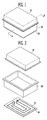
- FIG. 1 illustrates a perspective view showing a case for a battery pack, which includes a heat exchange member according to an embodiment.
- FIG. 2 illustrates an exploded perspective view showing the case according to the embodiment illustrated in FIG. 1 .
- the case according to this embodiment may include a case member that includes upper and lower cases 10 and 20 that accommodate a plurality of battery cells therein and a heat exchange member 30 provided on an outer bottom surface of the lower case 20.
- a flow path 31 through which a cooling medium flows may be formed in an upper surface of the heat exchange member 30.
- the upper surface of the heat exchange member 30 may be attached to the outer bottom surface of the lower case 20.
- the lower case 20 and the heat exchange member 30 may be integrally formed.
- a heat exchange medium may move through the flow path 31 of the heat exchange member 30.
- the heat exchange medium may be a refrigerant.
- the heat exchange medium may include at least one of ethylene glycol and propylene glycol.
- a lower case of a battery pack and a heat exchange member are separately manufactured and then connected to each other, using a bolt, a rivet, or the like.
- a component such as a bolt, however, is used, and a bolt fastening process is included, thereby increasing manufacturing time and cost.
- a separate cover is not provided to the heat exchange member 30 having the flow path 31 formed therein.
- the heat exchange member 30 may be attached directly to the outer bottom surface of the lower case 20, such that it may be possible to omit a component such as a cover, thereby reducing unit cost.
- the heat exchange member 30 may be welded to the lower case 20 through brazing, and each of the lower case 20 and the heat exchange member 30 may be manufactured through die-casting.
- a battery module may include a plurality of battery cells arranged in one direction. Each battery cell may be provided with a cap plate having a terminal portion formed on an upper surface thereof. In addition, the battery cell may include with a bottom surface provided opposite to the cap plate. A heat exchange member may be provided on the bottom surface of the battery cell. A single heat exchange member extending along the stacking direction of the battery cells may be provided on the bottom surfaces of all the battery cells in each battery module.
- a battery pack may be formed of battery modules. A heat exchange member, preferably a common heat exchange member is attached to all battery cells within a battery module or within the battery pack.
- the battery cell may include a battery cell case of which one surface is opened, and an electrode assembly and an electrolyte, which are accommodated in the battery cell case.
- the electrode assembly and the electrolyte may generate energy through an electrochemical reaction therebetween, and the battery cell case may be sealed with the cap plate.
- the cap plate may be provided with the terminal portion and a vent portion.
- the terminal portion may include positive and negative electrode terminals having different polarities from each other.
- the vent portion may be a safety device of the battery cell, and may act as a passage through which gas generated inside the battery cell is exhausted to an outside of the battery cell.
- Positive and negative electrode terminals of battery cells adjacent to each other may be electrically connected through a bus-bar.
- the bus-bar may be fixed to the positive and negative electrode terminals using a member such as a nut.
- the plurality of battery cells may be aligned in one direction.
- One or more plates may be used to maintain the alignment state of the battery cells.
- the plates may be used to fix the plurality of the battery cells and may be variously modified according to the design of the battery module.
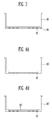
- FIG. 3 illustrates a sectional view taken along line A-A' of FIG. 1 .
- the heat exchange member 30 may be provided on the outer bottom surface of the lower case 20.
- the flow path 31 through which the cooling medium moves may be formed in the upper surface of the heat exchange member 30.
- the upper surface of the heat exchange member 30 may be attached to the outer bottom surface of the lower case 20.
- the bottom surface of the lower case 20 may seal the flow path 31 formed in the heat exchange member 30, such that it may be possible to prevent the occurrence of leakage of the heat exchange medium moving through the flow path 31.
- the height of the case may be reduced by omitting a cover of the heat exchange member 30.
- the case may be installed even in a narrow space.
- the heat exchange member 30 may be formed in the shape of a plate having a predetermined thickness.
- the heat exchange member 30 may be used to control heat generated in the battery cell.
- the flow path 31 through which the heat exchange medium flows to exchange heat with the battery module, i.e., the battery cell, may be provided in the heat exchange member 30.
- the heat exchange member 30 may be welded to the bottom surface of the lower case 20 through brazing.
- Each of the heat exchange member 30 and the lower case 20 may be manufactured through die-casting, thereby reducing an accumulated assembly tolerance that may be generated in the manufacturing of the case.
- Brazing is a kind of soldering, and is a method of coupling base materials to each other without melting the base materials by penetrating a melted adhesive between the base materials.
- An adhesive having a melting point lower than that of the base material may be used as an adhesive for brazing.
- the die-casting is one of casting methods, and is a precision casting method of injecting a melted metal into a mold made of steel exactly machined to completely correspond to a required casting shape, thereby obtaining a casting equal to the mold.
- the bottom surface of the lower case 20 and the contact surface of the heat exchange member 30 may be adhered more closely to each other, and the contact surface between the bottom surface of the lower case 20 and the heat exchange member 30 may be increased, thereby improving the reliability and stability of the battery pack.
- FIG. 4A illustrates a sectional view showing a case for a battery pack according to another embodiment.
- FIG. 4B illustrates a sectional view showing the case including a heat exchange member according to the embodiment.
- a flow path 31' through which a cooling medium moves may be formed in an inner bottom surface of the case 20'.
- a heat exchange member 30' may be attached to the inner bottom surface of the case 20'.
- the heat exchange member 30' may be formed in the shape of a plate to seal the flow path 31' formed in the inner bottom surface of the case 20'. It may be possible to prevent a heat exchange medium flowing through the flow path 31' from being leaked and then condensed inside the battery pack.
- the flow path 31' may be formed in the inner bottom surface of the case 20', and the case 20' and the heat exchange member 30' may be welded through brazing such that the plate-shaped heat exchange member 30' seals the flow path 31'.
- the case 20' and the heat exchange member 30' may be integrally formed.
- a heat shield material such as air layer, paper, or rubber may be provided at a lower portion of the heat exchange member 30'.
- the case 20' may be a lower case that is used with the upper case 10 illustrated in FIGS. 1 and 2 to accommodate a battery pack.
- a high-power and large-capacity battery pack generates a large amount of heat in a charging/discharging process thereof.
- a heat exchange member may be mounted in the high-power and high-capacity battery pack. Mounting a heat exchange member to a battery pack may increase manufacturing time and cost, and a mounted heat exchange member may take up space.
- one surface of a case may be substituted for a cover of the heat exchange member, so that the case and the heat exchange member may be integrally manufactured.
- the heat exchange member may be formed integrally with any other surface of the case member.
- case and the heat exchange member may be welded to each other through brazing, so that a bolt fastening process may be omitted, thereby reducing manufacturing time and cost.
- it may be possible to reduce an accumulated assembly tolerance generated in the manufacturing of the case, thereby improving product accuracy.
- the contact area between the case and the heat exchange member may be increased, thereby improving the reliability and stability of the battery pack.
- Example embodiments have been disclosed herein, and although specific terms are employed, they are used and are to be interpreted in a generic and descriptive sense only and not for purpose of limitation. In some instances, as would be apparent to one of ordinary skill in the art as of the filing of the present application, features, characteristics, and/or elements described in connection with a particular embodiment may be used singly or in combination with features, characteristics, and/or elements described in connection with other embodiments unless otherwise specifically indicated.
Landscapes
- Chemical & Material Sciences (AREA)
- Chemical Kinetics & Catalysis (AREA)
- Electrochemistry (AREA)
- General Chemical & Material Sciences (AREA)
- Engineering & Computer Science (AREA)
- Manufacturing & Machinery (AREA)
- Secondary Cells (AREA)
- Battery Mounting, Suspending (AREA)
Abstract
A case for a battery pack includes a case member (10, 20) configured to accommodate a plurality of battery cells therein and a heat exchange member (30) on any one surface of the case member (10, 20), the heat exchange member (30) being integrally formed with the case member (10, 20).

Description
- Embodiments relate to a case for a battery pack.
- In general, battery cells are used as energy sources for mobile devices, electric vehicles, hybrid vehicles, and the like. The shape of the battery cell may be variously changed depending on the kind of external device to which the battery cell is applied.
- In an electric vehicle or hybrid vehicle that consumes a large amount of power in long-time driving and high-power driving, a large-capacity battery module may be configured by electrically connecting a plurality of battery cells in order to increase power and capacity. The output voltage or output current of the battery module may be increased according to the number of battery cells built in the battery module. In addition, a battery pack may be configured by electrically connecting such battery modules.
- Embodiments are directed to a case for a battery pack including a case member configured to accommodate a plurality of battery cells therein, and a heat exchange member on any one surface of the case member, the heat exchange member being integrally formed with the case member.
- An upper surface of the heat exchange member may include a flow path through which a cooling medium moves. The upper surface of the heat exchange member may be attached to an outer bottom surface of the case member. The flow path is sealed by the outer bottom surface of the case member.
- An inner bottom surface of the case member may include a flow path through which a cooling medium moves. The heat exchange member may be attached to the inner bottom surface of the case member. The flow path is sealed by the heat exchange member.
- The heat exchange member and the case member are separate elements integrally formed to form the case. The heat exchange member and the surface of the case member it is integrally formed with are separate elements.
- The heat exchange member has a heat conductivity larger than the heat conductivity of the case member. Preferably, the material of the heat exchange member has a heat conductivity larger than the material of the case member.
- The heat exchange member may be in a shape of a plate.
- A heat shield material may be at a lower portion of the heat exchange member.
- The heat exchange member may be welded to the case member through brazing.
- The case member and the heat exchange member may be manufactured through die-casting.
- Further provided is a battery pack comprising a case according to the invention, and a plurality of battery cells accommodated in the case.
- Features will become apparent to those of skill in the art by describing in detail exemplary embodiments with reference to the attached drawings in which:
-
FIG. 1 illustrates a perspective view showing a case for a battery pack, which includes a heat exchange member according to an embodiment. -
FIG. 2 illustrates an exploded perspective view showing the case according to the embodiment. -
FIG. 3 illustrates a sectional view taken along line A-A' ofFIG. 1 . -
FIG. 4A illustrates a sectional view showing a case for a battery pack according to another embodiment. -
FIG. 4B illustrates a sectional view showing the case including a heat exchange member according to the embodiment illustrated inFIG. 4A . - Example embodiments will now be described more fully hereinafter with reference to the accompanying drawings; however, they may be embodied in different forms and should not be construed as limited to the embodiments set forth herein. Rather, these embodiments are provided so that this disclosure will be thorough and complete, and will fully convey exemplary implementations to those skilled in the art.
- In the drawing figures, the dimensions of layers and regions may be exaggerated for clarity of illustration. Like reference numerals refer to like elements throughout.
-
FIG. 1 illustrates a perspective view showing a case for a battery pack, which includes a heat exchange member according to an embodiment.FIG. 2 illustrates an exploded perspective view showing the case according to the embodiment illustrated inFIG. 1 . - Referring to
FIGS. 1 and 2 , the case according to this embodiment may include a case member that includes upper andlower cases heat exchange member 30 provided on an outer bottom surface of thelower case 20. Aflow path 31 through which a cooling medium flows may be formed in an upper surface of theheat exchange member 30. The upper surface of theheat exchange member 30 may be attached to the outer bottom surface of thelower case 20. Thelower case 20 and theheat exchange member 30 may be integrally formed. - A heat exchange medium may move through the
flow path 31 of theheat exchange member 30. The heat exchange medium may be a refrigerant. The heat exchange medium may include at least one of ethylene glycol and propylene glycol. - Generally, a lower case of a battery pack and a heat exchange member are separately manufactured and then connected to each other, using a bolt, a rivet, or the like. A component such as a bolt, however, is used, and a bolt fastening process is included, thereby increasing manufacturing time and cost.
- According to embodiments, a separate cover is not provided to the
heat exchange member 30 having theflow path 31 formed therein. Instead, theheat exchange member 30 may be attached directly to the outer bottom surface of thelower case 20, such that it may be possible to omit a component such as a cover, thereby reducing unit cost. Theheat exchange member 30 may be welded to thelower case 20 through brazing, and each of thelower case 20 and theheat exchange member 30 may be manufactured through die-casting. - Accordingly, it may be possible to reduce an accumulated assembly tolerance generated in the manufacturing of the case, thereby improving product accuracy. Further, as the contact area between the outer bottom surface of the
lower case 20 and theheat exchange member 30 increases, it may be possible to improve the reliability and the stability of the case. - Hereinafter, a battery module will be briefly described.
- A battery module may include a plurality of battery cells arranged in one direction. Each battery cell may be provided with a cap plate having a terminal portion formed on an upper surface thereof. In addition, the battery cell may include with a bottom surface provided opposite to the cap plate. A heat exchange member may be provided on the bottom surface of the battery cell. A single heat exchange member extending along the stacking direction of the battery cells may be provided on the bottom surfaces of all the battery cells in each battery module. A battery pack may be formed of battery modules. A heat exchange member, preferably a common heat exchange member is attached to all battery cells within a battery module or within the battery pack.
- The battery cell may include a battery cell case of which one surface is opened, and an electrode assembly and an electrolyte, which are accommodated in the battery cell case. The electrode assembly and the electrolyte may generate energy through an electrochemical reaction therebetween, and the battery cell case may be sealed with the cap plate. The cap plate may be provided with the terminal portion and a vent portion. The terminal portion may include positive and negative electrode terminals having different polarities from each other. The vent portion may be a safety device of the battery cell, and may act as a passage through which gas generated inside the battery cell is exhausted to an outside of the battery cell. Positive and negative electrode terminals of battery cells adjacent to each other may be electrically connected through a bus-bar. The bus-bar may be fixed to the positive and negative electrode terminals using a member such as a nut.
- The plurality of battery cells may be aligned in one direction. One or more plates may be used to maintain the alignment state of the battery cells. The plates may be used to fix the plurality of the battery cells and may be variously modified according to the design of the battery module.
-
FIG. 3 illustrates a sectional view taken along line A-A' ofFIG. 1 . - Referring to
FIG. 3 , theheat exchange member 30 may be provided on the outer bottom surface of thelower case 20. Theflow path 31 through which the cooling medium moves may be formed in the upper surface of theheat exchange member 30. The upper surface of theheat exchange member 30 may be attached to the outer bottom surface of thelower case 20. The bottom surface of thelower case 20 may seal theflow path 31 formed in theheat exchange member 30, such that it may be possible to prevent the occurrence of leakage of the heat exchange medium moving through theflow path 31. Particularly, when the case configured described above is installed in a vehicle, the height of the case may be reduced by omitting a cover of theheat exchange member 30. Thus, the case may be installed even in a narrow space. - The
heat exchange member 30 according to this embodiment may be formed in the shape of a plate having a predetermined thickness. Theheat exchange member 30 may be used to control heat generated in the battery cell. Theflow path 31 through which the heat exchange medium flows to exchange heat with the battery module, i.e., the battery cell, may be provided in theheat exchange member 30. - The
heat exchange member 30 may be welded to the bottom surface of thelower case 20 through brazing. Each of theheat exchange member 30 and thelower case 20 may be manufactured through die-casting, thereby reducing an accumulated assembly tolerance that may be generated in the manufacturing of the case. - Brazing is a kind of soldering, and is a method of coupling base materials to each other without melting the base materials by penetrating a melted adhesive between the base materials. An adhesive having a melting point lower than that of the base material may be used as an adhesive for brazing. In addition, the die-casting is one of casting methods, and is a precision casting method of injecting a melted metal into a mold made of steel exactly machined to completely correspond to a required casting shape, thereby obtaining a casting equal to the mold. Accordingly, the bottom surface of the
lower case 20 and the contact surface of theheat exchange member 30 may be adhered more closely to each other, and the contact surface between the bottom surface of thelower case 20 and theheat exchange member 30 may be increased, thereby improving the reliability and stability of the battery pack. -
FIG. 4A illustrates a sectional view showing a case for a battery pack according to another embodiment.FIG. 4B illustrates a sectional view showing the case including a heat exchange member according to the embodiment. - Referring to
FIGS. 4A and 4B , in the case 20' according to this embodiment, a flow path 31' through which a cooling medium moves may be formed in an inner bottom surface of the case 20'. In addition, a heat exchange member 30' may be attached to the inner bottom surface of the case 20'. The heat exchange member 30' may be formed in the shape of a plate to seal the flow path 31' formed in the inner bottom surface of the case 20'. It may be possible to prevent a heat exchange medium flowing through the flow path 31' from being leaked and then condensed inside the battery pack. - The flow path 31' may be formed in the inner bottom surface of the case 20', and the case 20' and the heat exchange member 30' may be welded through brazing such that the plate-shaped heat exchange member 30' seals the flow path 31'. As such, the case 20' and the heat exchange member 30' may be integrally formed.
- In addition, a heat shield material such as air layer, paper, or rubber may be provided at a lower portion of the heat exchange member 30'.
- According to some implementations, the case 20' may be a lower case that is used with the
upper case 10 illustrated inFIGS. 1 and 2 to accommodate a battery pack. - By way of summation and review, a high-power and large-capacity battery pack generates a large amount of heat in a charging/discharging process thereof. To dissipate heat generated in the battery cells, a heat exchange member may be mounted in the high-power and high-capacity battery pack. Mounting a heat exchange member to a battery pack may increase manufacturing time and cost, and a mounted heat exchange member may take up space.
- According to embodiments, one surface of a case may be substituted for a cover of the heat exchange member, so that the case and the heat exchange member may be integrally manufactured. Thus, it may be possible to omit a component, thereby reducing unit cost. Though the previous embodiments have shown a heat exchange member integrally formed with a lower surface of the case member, the heat exchange member may be formed integrally with any other surface of the case member.
- Further, the case and the heat exchange member may be welded to each other through brazing, so that a bolt fastening process may be omitted, thereby reducing manufacturing time and cost. In addition, it may be possible to reduce an accumulated assembly tolerance generated in the manufacturing of the case, thereby improving product accuracy.
- Further, the contact area between the case and the heat exchange member may be increased, thereby improving the reliability and stability of the battery pack.
- Example embodiments have been disclosed herein, and although specific terms are employed, they are used and are to be interpreted in a generic and descriptive sense only and not for purpose of limitation. In some instances, as would be apparent to one of ordinary skill in the art as of the filing of the present application, features, characteristics, and/or elements described in connection with a particular embodiment may be used singly or in combination with features, characteristics, and/or elements described in connection with other embodiments unless otherwise specifically indicated.
Claims (12)
- A case for a battery pack, the case comprising:a case member (10, 20) configured to accommodate a plurality of battery cells therein; anda heat exchange member (30) on any one surface of the case member (10, 20), the heat exchange member (30) being integrally formed with the case member (10, 20).
- The case as claimed in claim 1, wherein:an upper surface of the heat exchange member (30) includes a flow path (31) adapted to accommodate a cooling medium therein, andthe upper surface of the heat exchange member (30) is attached to an outer bottom surface of the case member (10, 20).
- The case as claimed in claim 2, wherein flow path (31) is sealed by the outer bottom surface of the case member (10, 20).
- The case as claimed in claim 1, wherein:an inner bottom surface of the case member (10, 20') includes a flow path (31') adapted to accommodate a cooling medium therein, andthe heat exchange member (30') is attached to the inner bottom surface of the case member.
- The case as claimed in claim 4, wherein flow path (31') is sealed by the heat exchange member (30').
- The case as claimed in claim 4 or 5, wherein the heat exchange member (30') is in a shape of a plate.
- The case as claimed in one of the previous claims, wherein a heat shield material is provided at a lower portion of the heat exchange member (30).
- The case as claimed in one of the previous claims, wherein the heat exchange member (30) is welded to the case member (10, 20) through brazing.
- The case as claimed in one of the previous claims 1 to 7, wherein the case member (10, 20) and the heat exchange member (30) are manufactured through die-casting.
- The case as claimed in one of the previous claims, wherein the heat exchange member (30) has a larger heat conductivity than the case member (10, 20).
- The case as claimed in one of the previous claims, wherein the heat exchange member (30) has a larger heat conductivity than the surface of the case member (10, 20) the heat exchange member (30) is attached thereto.
- A battery pack comprising
a case according to one of the previous claims,
a plurality of battery cells accommodated in the case.
Applications Claiming Priority (1)
| Application Number | Priority Date | Filing Date | Title |
|---|---|---|---|
| KR1020140017717A KR102198000B1 (en) | 2014-02-17 | 2014-02-17 | Case for battery pack |
Publications (1)
| Publication Number | Publication Date |
|---|---|
| EP2908377A1 true EP2908377A1 (en) | 2015-08-19 |
Family
ID=52469709
Family Applications (1)
| Application Number | Title | Priority Date | Filing Date |
|---|---|---|---|
| EP15155209.8A Withdrawn EP2908377A1 (en) | 2014-02-17 | 2015-02-16 | Case for battery pack with cooling system |
Country Status (4)
| Country | Link |
|---|---|
| US (1) | US10205144B2 (en) |
| EP (1) | EP2908377A1 (en) |
| KR (1) | KR102198000B1 (en) |
| CN (1) | CN104851996A (en) |
Cited By (6)
| Publication number | Priority date | Publication date | Assignee | Title |
|---|---|---|---|---|
| FR3062749A1 (en) * | 2018-04-10 | 2018-08-10 | Sogefi Air & Cooling | BATTERY UNIT INTEGRATING THERMAL EXCHANGE AREAS |
| US10784544B2 (en) | 2017-03-07 | 2020-09-22 | Dr. Ing. H.C. F. Porsche Aktiengesellschaft | Battery module for use in a high-voltage energy store |
| EP3726612A1 (en) * | 2019-04-15 | 2020-10-21 | Robert Bosch GmbH | Battery and use of same |
| EP3796415A1 (en) * | 2019-09-18 | 2021-03-24 | Robert Bosch GmbH | Battery and use of such a battery |
| EP3806230A1 (en) * | 2019-10-07 | 2021-04-14 | Robert Bosch GmbH | Battery and use of such a battery |
| DE102020110906A1 (en) | 2020-04-22 | 2021-10-28 | FRÖTEK Vermögensverwaltung GmbH | Battery case |
Families Citing this family (30)
| Publication number | Priority date | Publication date | Assignee | Title |
|---|---|---|---|---|
| DE102015216029A1 (en) * | 2015-08-21 | 2017-02-23 | Robert Bosch Gmbh | battery Pack |
| DE102016117442A1 (en) * | 2016-09-16 | 2018-03-22 | Dr. Ing. H.C. F. Porsche Aktiengesellschaft | Battery housing for a traction battery |
| KR102253786B1 (en) * | 2016-10-06 | 2021-05-20 | 주식회사 엘지화학 | Battery Module Comprising Module Case Having Integrally Coupled Heat Sink |
| KR101750029B1 (en) * | 2017-02-24 | 2017-06-23 | 엠에이치기술개발 주식회사 | Cooling apparatus for battery and manufacturing method of the same |
| KR101761678B1 (en) * | 2017-02-24 | 2017-07-27 | 엠에이치기술개발 주식회사 | Manufacturing method of cooling apparatus for battery |
| DE102017203648A1 (en) | 2017-03-07 | 2018-09-13 | Mahle International Gmbh | Akkumulatortemperieranordnung |
| DE102017110578A1 (en) | 2017-05-16 | 2018-11-22 | Dr. Ing. H.C. F. Porsche Aktiengesellschaft | Automotive high-voltage energy storage |
| KR102002551B1 (en) | 2017-09-07 | 2019-10-01 | (주)케이에이치바텍 | Manufacturing method for battery housing for electric vehicle and structure for joining battery cover |
| DE102018203920A1 (en) * | 2018-03-14 | 2019-09-19 | Audi Ag | Spare wheel well for a motor vehicle and method for producing a spare wheel well |
| FR3062521B1 (en) * | 2018-04-10 | 2023-09-08 | Sogefi Air & Cooling | BATTERY UNIT WITH MEANS OF TEMPERATURE REGULATION INTEGRATED IN THE HOUSING |
| FR3081261B1 (en) | 2018-05-18 | 2020-04-24 | Faurecia Systemes D'echappement | BATTERY AND VEHICLE EQUIPPED WITH SUCH A BATTERY |
| JP6743098B2 (en) * | 2018-08-31 | 2020-08-19 | 本田技研工業株式会社 | Battery pack for electric vehicle |
| DE102018217102A1 (en) | 2018-10-05 | 2020-04-09 | Mahle International Gmbh | Accumulator arrangement |
| JP6721654B2 (en) * | 2018-10-11 | 2020-07-15 | 本田技研工業株式会社 | Battery pack for electric vehicle |
| DE102018131374B4 (en) * | 2018-12-07 | 2025-07-17 | Benteler Automobiltechnik Gmbh | Modular battery carrier |
| DE102018131376B4 (en) * | 2018-12-07 | 2024-05-23 | Benteler Automobiltechnik Gmbh | Battery carrier with surrounding frame and defined adhesive gap |
| JP7230513B2 (en) * | 2019-01-10 | 2023-03-01 | トヨタ自動車株式会社 | battery pack |
| KR102842878B1 (en) | 2019-09-30 | 2025-08-07 | 주식회사 엘지에너지솔루션 | Battery Case Integrated Colling Structure and Method of Battery Case |
| KR102949002B1 (en) | 2020-04-22 | 2026-04-03 | 주식회사 엘지에너지솔루션 | Battery module and battery pack including the same |
| KR102951964B1 (en) * | 2020-04-22 | 2026-04-10 | 주식회사 엘지에너지솔루션 | Battery module and manufacturing method thereof |
| KR102772825B1 (en) | 2020-04-29 | 2025-02-24 | 주식회사 엘지에너지솔루션 | Battery pack and device including the same |
| KR102839240B1 (en) * | 2020-08-07 | 2025-07-25 | 주식회사 엘지에너지솔루션 | Battery module with improved fastening of cooling plate using reinforcment beam and battery pack comprising the same |
| KR20220041428A (en) * | 2020-09-25 | 2022-04-01 | 주식회사 엘지에너지솔루션 | Battery module, battery pack and vehicle including the same |
| WO2022082393A1 (en) | 2020-10-19 | 2022-04-28 | 江苏时代新能源科技有限公司 | Box body for battery, battery, electric apparatus, and battery manufacturing method and device |
| KR102917117B1 (en) * | 2020-11-05 | 2026-01-22 | 주식회사 엘지에너지솔루션 | Battery module and battery pack including the same |
| KR20230134552A (en) * | 2021-03-01 | 2023-09-21 | 닛폰세이테츠 가부시키가이샤 | battery unit |
| DE102021204787A1 (en) * | 2021-05-11 | 2022-11-17 | Robert Bosch Gesellschaft mit beschränkter Haftung | battery and use of one |
| JP7596993B2 (en) * | 2021-09-24 | 2024-12-10 | トヨタ自動車株式会社 | Power storage device |
| EP4611127A4 (en) * | 2022-12-02 | 2025-12-31 | Lg Energy Solution Ltd | BATTERY PACK AND METHOD FOR MANUFACTURING IT |
| KR20250001366U (en) | 2024-03-06 | 2025-09-15 | 주식회사 테스크 | battery case |
Citations (7)
| Publication number | Priority date | Publication date | Assignee | Title |
|---|---|---|---|---|
| US20110200861A1 (en) * | 2010-02-12 | 2011-08-18 | Asia Vital Components Co., Ltd. | Heat-dissipating modlue for automobile battery |
| US20110212355A1 (en) * | 2010-02-26 | 2011-09-01 | Gm Global Technology Operations, Inc. | U-formed cooling plate with solid fins for lithium pouch cells |
| US20120087091A1 (en) * | 2010-10-11 | 2012-04-12 | GM Global Technology Operations LLC | Integrated Thermal And Structural Management Solution For Rechargeable Energy Storage System Assembly |
| US20120196157A1 (en) * | 2011-01-27 | 2012-08-02 | Dr. Ing. H.C.F. Porsche Aktiengesellschaft | Battery |
| US20120227931A1 (en) * | 2009-09-10 | 2012-09-13 | Thomas Heckenberger | Method for producing an energy storage device holder for a vehicle |
| DE102012012663A1 (en) * | 2012-06-23 | 2013-12-24 | Volkswagen Aktiengesellschaft | Housing for carrying and cooling lithium ion battery pack for drive of electric vehicle, has separation body arranged between operating device and trough, where body and trough limit intermediate space to guide coolant in flow-proof design |
| US20140011059A1 (en) * | 2011-03-31 | 2014-01-09 | Hiroyuki Hashimoto | Power supply device and vehicle equipped therewith |
Family Cites Families (8)
| Publication number | Priority date | Publication date | Assignee | Title |
|---|---|---|---|---|
| DE602006000126T2 (en) * | 2005-03-25 | 2008-07-03 | Samsung SDI Co., Ltd., Suwon | battery module |
| JP4525695B2 (en) * | 2007-03-30 | 2010-08-18 | トヨタ自動車株式会社 | Power storage device |
| US9196938B2 (en) * | 2010-07-06 | 2015-11-24 | Samsung Sdi Co., Ltd. | Battery module |
| DE202010018541U1 (en) * | 2010-07-30 | 2017-07-26 | Valeo Klimasysteme Gmbh | Cooling device and vehicle battery assembly |
| KR101201742B1 (en) * | 2010-11-05 | 2012-11-15 | 에스비리모티브 주식회사 | Battery module |
| KR20120096133A (en) | 2011-02-22 | 2012-08-30 | 주식회사 엘지화학 | Cooling member of improved cooling efficiency and battery module employed with the same |
| DE202012101076U1 (en) * | 2011-04-14 | 2012-04-19 | Visteon Global Technologies, Inc. | Device for cooling batteries, in particular for motor vehicles |
| KR102002043B1 (en) * | 2012-01-10 | 2019-07-19 | 에스케이이노베이션 주식회사 | Secondary battery module and Secondary battery pack |
-
2014
- 2014-02-17 KR KR1020140017717A patent/KR102198000B1/en active Active
-
2015
- 2015-02-04 US US14/613,559 patent/US10205144B2/en active Active
- 2015-02-12 CN CN201510075855.5A patent/CN104851996A/en active Pending
- 2015-02-16 EP EP15155209.8A patent/EP2908377A1/en not_active Withdrawn
Patent Citations (7)
| Publication number | Priority date | Publication date | Assignee | Title |
|---|---|---|---|---|
| US20120227931A1 (en) * | 2009-09-10 | 2012-09-13 | Thomas Heckenberger | Method for producing an energy storage device holder for a vehicle |
| US20110200861A1 (en) * | 2010-02-12 | 2011-08-18 | Asia Vital Components Co., Ltd. | Heat-dissipating modlue for automobile battery |
| US20110212355A1 (en) * | 2010-02-26 | 2011-09-01 | Gm Global Technology Operations, Inc. | U-formed cooling plate with solid fins for lithium pouch cells |
| US20120087091A1 (en) * | 2010-10-11 | 2012-04-12 | GM Global Technology Operations LLC | Integrated Thermal And Structural Management Solution For Rechargeable Energy Storage System Assembly |
| US20120196157A1 (en) * | 2011-01-27 | 2012-08-02 | Dr. Ing. H.C.F. Porsche Aktiengesellschaft | Battery |
| US20140011059A1 (en) * | 2011-03-31 | 2014-01-09 | Hiroyuki Hashimoto | Power supply device and vehicle equipped therewith |
| DE102012012663A1 (en) * | 2012-06-23 | 2013-12-24 | Volkswagen Aktiengesellschaft | Housing for carrying and cooling lithium ion battery pack for drive of electric vehicle, has separation body arranged between operating device and trough, where body and trough limit intermediate space to guide coolant in flow-proof design |
Cited By (13)
| Publication number | Priority date | Publication date | Assignee | Title |
|---|---|---|---|---|
| US10784544B2 (en) | 2017-03-07 | 2020-09-22 | Dr. Ing. H.C. F. Porsche Aktiengesellschaft | Battery module for use in a high-voltage energy store |
| CN111971816A (en) * | 2018-04-10 | 2020-11-20 | 索格菲空气冷却公司 | Battery cell comprising a heat exchange region |
| WO2019197338A1 (en) * | 2018-04-10 | 2019-10-17 | Sogefi Air & Cooling | Battery unit incorporating heat exchange areas |
| WO2019197340A1 (en) * | 2018-04-10 | 2019-10-17 | Sogefi Air & Cooling | Battery unit comprising built-in temperature control means |
| FR3079971A1 (en) * | 2018-04-10 | 2019-10-11 | Sogefi Air & Cooling | BATTERY UNIT WITH INTEGRATED TEMPERATURE CONTROL MEANS |
| FR3062749A1 (en) * | 2018-04-10 | 2018-08-10 | Sogefi Air & Cooling | BATTERY UNIT INTEGRATING THERMAL EXCHANGE AREAS |
| CN111971816B (en) * | 2018-04-10 | 2023-06-02 | 索格菲空气冷却公司 | Battery cells containing heat exchange areas |
| EP3726612A1 (en) * | 2019-04-15 | 2020-10-21 | Robert Bosch GmbH | Battery and use of same |
| EP3796415A1 (en) * | 2019-09-18 | 2021-03-24 | Robert Bosch GmbH | Battery and use of such a battery |
| US11495859B2 (en) | 2019-09-18 | 2022-11-08 | Robert Bosch Gmbh | Battery having a temperature control structure and use of such a battery |
| EP3806230A1 (en) * | 2019-10-07 | 2021-04-14 | Robert Bosch GmbH | Battery and use of such a battery |
| US11626643B2 (en) | 2019-10-07 | 2023-04-11 | Robert Bosch Gmbh | Battery and use of such a battery |
| DE102020110906A1 (en) | 2020-04-22 | 2021-10-28 | FRÖTEK Vermögensverwaltung GmbH | Battery case |
Also Published As
| Publication number | Publication date |
|---|---|
| KR20150096883A (en) | 2015-08-26 |
| CN104851996A (en) | 2015-08-19 |
| KR102198000B1 (en) | 2021-01-04 |
| US10205144B2 (en) | 2019-02-12 |
| US20150236314A1 (en) | 2015-08-20 |
Similar Documents
| Publication | Publication Date | Title |
|---|---|---|
| US10205144B2 (en) | Case for battery pack | |
| KR102259217B1 (en) | Battery System and Vehicle Comprising the Same | |
| US10978759B2 (en) | Battery module having improved cooling performance | |
| EP2538466B1 (en) | Battery module including sensing members with novel structure | |
| EP3151307B1 (en) | Battery module and battery pack comprising same | |
| EP3136497B1 (en) | Battery module including water cooling structure | |
| US9722222B2 (en) | Battery module | |
| JP5541250B2 (en) | Secondary battery | |
| US8623537B2 (en) | Rechargeable battery and battery module | |
| EP3358668B1 (en) | Battery module, battery pack and vehicle having same | |
| KR102059077B1 (en) | Battery module, battery pack comprising the battery module and vehicle comprising the battery pack | |
| US11342632B2 (en) | Battery module | |
| KR102523098B1 (en) | Secondary Battery and Battery Module Having the Same | |
| US10497989B2 (en) | Battery module including voltage sensing member having receptacle structure | |
| US11984612B2 (en) | Battery module comprising module housing | |
| US20140315069A1 (en) | Battery pack | |
| US20150207189A1 (en) | Heat exchange member of battery pack | |
| KR102013411B1 (en) | Battery module and battery pack including the same | |
| KR20170098590A (en) | The cartridge, Battery module including the cartridge, Battery pack | |
| US20140308552A1 (en) | Battery pack | |
| KR101658587B1 (en) | Lithium Secondary Battery and Battery Pack Comprising The Same | |
| EP3385997A1 (en) | Secondary cell for a traction battery and method for manufacturing a secondary cell | |
| CN120858486A (en) | battery pack | |
| KR20160058474A (en) | Battery Cell Having Through Hole |
Legal Events
| Date | Code | Title | Description |
|---|---|---|---|
| PUAI | Public reference made under article 153(3) epc to a published international application that has entered the european phase |
Free format text: ORIGINAL CODE: 0009012 |
|
| AK | Designated contracting states |
Kind code of ref document: A1 Designated state(s): AL AT BE BG CH CY CZ DE DK EE ES FI FR GB GR HR HU IE IS IT LI LT LU LV MC MK MT NL NO PL PT RO RS SE SI SK SM TR |
|
| AX | Request for extension of the european patent |
Extension state: BA ME |
|
| STAA | Information on the status of an ep patent application or granted ep patent |
Free format text: STATUS: THE APPLICATION IS DEEMED TO BE WITHDRAWN |
|
| 18D | Application deemed to be withdrawn |
Effective date: 20160220 |