EP2910106B1 - Barre de coupe pour une moissonneuse - Google Patents
Barre de coupe pour une moissonneuse Download PDFInfo
- Publication number
- EP2910106B1 EP2910106B1 EP15154946.6A EP15154946A EP2910106B1 EP 2910106 B1 EP2910106 B1 EP 2910106B1 EP 15154946 A EP15154946 A EP 15154946A EP 2910106 B1 EP2910106 B1 EP 2910106B1
- Authority
- EP
- European Patent Office
- Prior art keywords
- cutting mechanism
- cutting
- pivotal movement
- switching state
- mechanism portion
- Prior art date
- Legal status (The legal status is an assumption and is not a legal conclusion. Google has not performed a legal analysis and makes no representation as to the accuracy of the status listed.)
- Active
Links
Images


Classifications
-
- A—HUMAN NECESSITIES
- A01—AGRICULTURE; FORESTRY; ANIMAL HUSBANDRY; HUNTING; TRAPPING; FISHING
- A01F—PROCESSING OF HARVESTED PRODUCE; HAY OR STRAW PRESSES; DEVICES FOR STORING AGRICULTURAL OR HORTICULTURAL PRODUCE
- A01F15/00—Baling presses for straw, hay or the like
- A01F15/08—Details
- A01F15/10—Feeding devices for the crop material e.g. precompression devices
-
- A—HUMAN NECESSITIES
- A01—AGRICULTURE; FORESTRY; ANIMAL HUSBANDRY; HUNTING; TRAPPING; FISHING
- A01D—HARVESTING; MOWING
- A01D90/00—Vehicles for carrying harvested crops with means for selfloading or unloading
- A01D90/02—Loading means
- A01D90/04—Loading means with additional cutting means
-
- A—HUMAN NECESSITIES
- A01—AGRICULTURE; FORESTRY; ANIMAL HUSBANDRY; HUNTING; TRAPPING; FISHING
- A01F—PROCESSING OF HARVESTED PRODUCE; HAY OR STRAW PRESSES; DEVICES FOR STORING AGRICULTURAL OR HORTICULTURAL PRODUCE
- A01F15/00—Baling presses for straw, hay or the like
- A01F15/08—Details
- A01F15/10—Feeding devices for the crop material e.g. precompression devices
- A01F2015/107—Means for withdrawing knives, rotor or walls of the feeding chamber in case of plugging or congestion
Definitions
- the invention relates to a cutting unit for a harvester, in particular a loader wagon or a baler.
- EP 1 062 860 A2 discloses a feed channel for a harvesting vehicle, in particular for an agricultural picking baler, which opens from below into a press channel and which is preceded by a cutting device with a downwardly pivotable cutting deck, wherein the feed channel has a lowerable Zustorykanal founded.
- a cutting machine for a harvesting machine which comprises a housing and a conveyor drum for crop, which is arranged rotatably mounted in the housing about an axis extending in a longitudinal direction of this axis of rotation, a guide element or bottom plate, which extends so circumferentially along the conveyor drum, in that a conveying channel for the crop is formed between the conveying drum and the guide element, a plurality of cutting blades extending in a cutting position through the guide element into the conveying channel and a bearing device on which the cutting knives are pivotably mounted.
- the guide element is firmly installed, so that in case of clogging of the conveyor channel this can not be opened.
- the invention is therefore an object of the invention to provide a cutting unit for a harvester, such as in particular a loader wagon or a baler, which allows improved access to its components.
- a cutting unit for a harvesting machine in particular a loading wagon or a baling press, comprises: a first cutting unit part comprising a housing and a conveyor drum for crop rotatably mounted in the housing about a rotation axis extending in a longitudinal direction thereof; a second cutting element part, which comprises a guide element which extends circumferentially along the conveyor drum, that between the conveyor drum and the guide element, a conveyor channel for the crop is formed, and which mounted about a parallel to the axis of rotation of the conveyor drum extending first Schneidtechniksschwenkachse pivotally mounted on the first cutting part is, so that as a first pivoting with the second cutting part, the guide element is pivotable radially away from the conveyor drum; a third cutting mechanism part which comprises a plurality of cutting blades extending in a cutting position through the guide element into the conveying channel and a bearing device on which the cutting blades are mounted, and which is pivotable on the second cutting mechanism part about a second cutting element pivot
- the second cutting mechanism part is mounted pivotably about the first cutting mechanism pivot axis on the first cutting mechanism part, so that as the first pivoting with the second cutting part, the guide element is wegschwenkbar radially from the conveyor drum, and the third cutting part about the second Schneidtechniksschwenkachse is pivotally mounted on the second cutting part, so that as the second pivoting with the third cutting part, the storage device and thus the cutting blade from Guide can be pivoted away, the cutting unit can be opened as needed both between the conveyor drum and guide element and between the guide element and cutting blades and thus provides improved access to its components.
- the switching device which can realize the three switching states, selectively different access variants can be selected or set.
- the cutting unit further comprises a drive device which is coupled to the third cutting mechanism part, so that both the first pivoting and the second pivoting can be driven by a drive movement of the drive device.
- the different access variants can be conveniently realized. Because the first pivoting and also the second pivoting can be driven by the drive device, the production outlay and the complexity of the cutting mechanism are not excessively increased when the operating comfort is increased.
- a maintenance position of the cutting can be realized by the second switching state of the switching device in conjunction with the drive of the drive device, a first release position of the cutting and can be through the third Switching state of the switching device in conjunction with the drive of the drive device realize a second release position of the cutting unit.
- the drive means may be e.g. comprise two movement-synchronized hydraulic piston-cylinder units, which are arranged at opposite longitudinal ends of the conveyor drum.
- the piston-cylinder units are each connected to one end (piston rod or cylinder) with a stationary element of the harvester or connected to the first cutting part as a stationary element or hinged thereto and with the other end (cylinder or piston rod) connected to the third cutting part or hinged thereto.
- Hydraulic piston-cylinder units can be integrated in a simple manner in the hydraulics of a harvester and thus reduce the driving effort for the drive device.
- the drive means could include other motors such as linear motors (e.g., spindle drive) or rotary motors (e.g., servomotors) for driving the first and second pivots.
- the third cutting mechanism part is set up so that in the first switching state, the second pivoting, wherein the third cutting part is pivoted away from the guide element with the bearing device of the cutting blade, with a ⁇ réellesschwenkwinkel of at least 70 degrees, preferably at least 80 degrees ,
- the switching device is set up to allow the first pivoting in the second switching state such that the radial movement of the guide element away from the conveying drum with the second cutting part is limited to a predetermined expansion pivot angle for widening the conveying channel.
- the extension pivot angle is less than 10 degrees, preferably about 5 degrees.
- the first pivoting with the civilsschwenkwinkel is made possible for widening of the conveying channel, in the case of a stuffer in the conveying channel by its extension, the stuffer can be easily pushed through the conveying channel.
- the delivery channel is not fully opened, but is only extended by the extension swivel angle, it is additionally advantageously avoided that crops such as grass fall back onto the field.
- the switching device is configured to allow the second pivoting in the second switching state such that with respect to a completed first pivoting the cutting blades can be moved out of the cutting position and thus out of the conveying channel by the pivoting away of the guiding element are pivotable.
- the switching device is set up to mechanically couple the second cutting mechanism part with a predetermined distance from the first cutting mechanism pivot axis without pivoting movement tolerance directly to the first cutting part in the first switching state.
- This direct mechanical coupling of the second cutting unit part to the first cutting unit part realized in a simple and robust manner, the blocking of the first pivoting in the first switching state. Furthermore, this embodiment of the blocking of the first pivoting or the coupling of the first and second cutting part can also be used advantageously in normal operation of the cutting unit, which can be dispensed with additional coupling devices.
- the switching device in the second switching state, is set up to mechanically couple the second cutting mechanism part directly to the first cutting part with a predetermined distance from the first cutting device pivot axis with pivoting movement tolerance.
- the switching device is arranged, in the third switching state, the second cutting part with a predetermined distance from the second Linking unit swivel axis without swivel movement tolerance to be mechanically coupled directly to the third cutting unit part.
- This direct mechanical coupling of the second cutting unit part to the third cutting unit part realizes the blocking of the second pivoting in the third switching state in a simple and robust manner. Furthermore, this embodiment of the blocking of the second pivoting or the coupling of the second and third cutting part can also be used advantageously in normal operation of the cutting unit, which can be dispensed with additional coupling devices.
- the switching device has a locking device, which is attached to the second cutting part and which comprises a first catch hook and a first pin, which are movably mounted to realize the first to third switching states; a second bolt provided on the first cutter part; and a second catch hook, which is provided on the third cutting part; wherein, for the first switching state, the first fishing hook is movable to a position in which the first fishing hook is engaged with the second bolt; wherein for the second switching state of the first fishing hook is movable to a position in which the first fishing hook is spaced from the second bolt on a pivoting path extending through the second bolt with respect to the first cutting unit pivot axis, so that the first fishing hook with completion of the first pivoting with the second pin engages; and wherein, for the third switching state, the first bolt is movable to a position in which the first bolt is engaged with the second fishing hook.
- This design of the switching device with fishing hook and bolt is simple and robust and thus particularly for the harsh operating conditions in Harvesting suitable. In addition, such a switching device can be realized with little effort.
- the switching device additionally produce at least a fourth switching state in which the first pivot and the second pivot are locked. More specifically, according to an embodiment of the invention for the fourth switching state, the first fishing hook is movable to the position in which the first fishing hook is engaged with the second bolt, and the first bolt is movable to the position in which the first bolt to the second Fishing hook is engaged.
- the fourth switching state can be advantageously used for the normal operation of the cutting unit.
- FIGS. 1 to 6 a cutting unit 10 of a harvester 1 (not shown in full) may be described in accordance with one embodiment of the invention.
- the harvesting machine 1 is preferably designed as a loader wagon or baler (in this case in particular as a loading wagon), wherein the cutting unit 10 is a pickup device (not shown in detail and not separately designated) with e.g. a spiked roller for receiving unillustrated crop (such as grass or other stalk and / or leaves) from an agricultural field.
- a pickup device not shown in detail and not separately designated
- unillustrated crop such as grass or other stalk and / or leaves
- the picked up by the pickup device or receiving device crop is then from this rotationally to an input 11 a of a conveyor channel 11 of the cutting unit 10 (see Fig. 3 ) and taken there by a conveyor drum 22 of the cutting unit 10 and further conveyed along the conveyor channel 11 for cutting. After cutting the crop, this is output at an output (not labeled) from the conveyor channel 11 and taken over there, for example by a pressing device or another conveyor (both latter not shown).
- the cutting unit 10 has a first cutting part 20, a second cutting part 30, a third cutting part 40 and a switching device 50.
- the first cutting unit part 20 comprises a first housing 21 fixedly attached to a frame 2 of the harvester 1 and a crop transporting drum 22 arranged in the first housing 21 about a longitudinal direction (y-axis direction eg in FIG Fig. 3 ) of this extending axis of rotation A1 is rotatably mounted on the first housing 21.
- the second cutting mechanism part 30 comprises a second housing 31 with a guide element 32 designed as a base plate, which extends circumferentially along the conveyor drum 22 in such a way that both in a normal operating position and in an in Fig. 1 shown maintenance position and in an in Fig. 3 shown first release position of the cutting unit 10 between the conveyor drum 22 and the guide element 32 of the conveyor channel 11 is formed for the crop.
- the second cutting unit part 30 is pivotally mounted about a parallel to the axis of rotation A1 of the conveyor drum 22 extending first Schneidtechniksschwenkachse A2 on the first housing 21 of the first cutting unit 20, so that as a first pivoting with the second cutting part 30, the second housing 31 with its guide element 32 radially from the conveyor drum 22 is pivotable away.
- the third cutting mechanism part 40 comprises a third housing 41 and arranged in the third housing 41 and supports a plurality of cutting blades 42 extending into the conveying channel 11 in a cutting position of these each through the guide element 32 (through a not designated respective slot-shaped opening in the guide element) (In the figures, only a cutting blade 42 is shown) and a cutter mechanism 43 for storing, securing and adjusting the cutting blade 42.
- the guide element 32 of the second Cutting unit part 30 shields the cutter mechanism 43 against the conveyor channel 11 during normal operation of the cutting unit 10.
- the cutting blades 42 are arranged side by side in a row in the longitudinal direction (y-axis direction) of the conveying drum 22 at a respective distance from each other so as to cover the entire working length of the conveying drum 22.
- the cutting mechanism mechanism 43 comprises a bearing device 44, on which the cutting blades 42 are respectively mounted, so that they extend around a cutting knife pivot axis A3 extending parallel to the axis of rotation A1 of the conveying drum 22 into the conveying channel 11 (cutting position) and out of the conveying channel 11 (an inoperative position or position) An alternative position) are pivotable.
- the cutting mechanism 43 also includes a cutting knife overload protection 45, which biases the cutting blade 42 with a predetermined biasing force into the cutting position and which when exceeding the biasing force (caused for example by a foreign body in the conveying channel 11) dodge against the biasing force in the alternate position of the cutting blade 42nd allows.
- the cutting mechanism mechanism 43 comprises an adjusting device (not designated), with which the cutting blade 42 can be brought in groups or as a whole in the inoperative position.
- the third cutting part 40 is in turn connected in quasi-series to the first and second cutting parts 20, 30 about a parallel to the first Schneidwerksschwenkachse extending second Schneidtechniksschwenkachse A4 pivotally mounted on the second cutting part 30, so that as a second pivoting with the third cutting part 40, the third Housing 41 and the components mounted therein cutting blade 42 and cutting mechanism 43 with the storage device 44 from the guide element 32 of the second cutting unit part 30 are wegschwenkbar.
- the second cutting unit part 30 is pivotally mounted about the first cutting unit pivot axis A2 on the first cutting part 20, so that the first pivoting with the second cutting part 30, the guide element 32 is radially wegschwenkbar of the conveyor drum 22, and the third cutting unit part 40 to the second cutting unit pivot axis A4 is pivotally mounted on the second cutting part 30, so that as the second pivoting with the third cutting part 40, the cutting mechanism 43 with the support means 44 and thus the cutting blades 42 are pivoted away from the guide element 32, the cutting unit 10 as required, both between conveyor drum 22nd and guide element 32 as well as between the guide element 32 and the third housing 41 are opened and thus provides improved access to its components.
- the switching device 50 which can realize three different switching states, selectively different access variants can be selected or set. More specifically, the switching device 50 is arranged to selectively connect an in Fig. 2 shown first switching state in which the first pivoting is locked and the second pivoting is possible, a in Fig. 4 shown second switching state, in which the first and the second pivoting are enabled, and a in Fig. 6 shown third switching state in which the first pivoting is enabled and the second pivoting is locked to produce.
- the switching device 50 has in detail a locking device 51 which is attached to the second housing 31 of the second cutting unit 30 and which comprises a first hebeiförmiges adjusting element 52 and a second hebeiförmiges adjusting element 56 which at each one longitudinal ends of these together about a
- a locking device 51 which is attached to the second housing 31 of the second cutting unit 30 and which comprises a first hebeiförmiges adjusting element 52 and a second hebeiförmiges adjusting element 56 which at each one longitudinal ends of these together about a
- a locking device 51 which is attached to the second housing 31 of the second cutting unit 30 and which comprises a first hebeiförmiges adjusting element 52 and a second hebeiförmiges adjusting element 56 which at each one longitudinal ends of these together about a
- a locking device 51 which is attached to the second housing 31 of the second cutting unit 30 and which comprises a first hebeiförmiges adjusting element 52 and a second hebeiför
- the first adjusting element 52 has, at its other longitudinal end facing away from the actuating element pivot axis A5, a first catch hook 53 with two latching sections 54, 55 spaced apart from one another.
- the second control element 56 has at its the actuator pivot axis A5 facing away from the other longitudinal end a first pin (pin) 57, which is guided in an arcuate slot 33 in the second housing 31 and which extends by a predetermined amount in the y-axis direction.
- the switching device 50 also has a second pin (pin) 58, which is mounted on the first housing 21 of the first cutting member 20 protrudes by a predetermined amount in the y-axis direction, and a second fishing hook 59, which on the third housing 41 of the third cutting unit 40th is molded and protrudes from it.
- a second pin (pin) 58 which is mounted on the first housing 21 of the first cutting member 20 protrudes by a predetermined amount in the y-axis direction
- a second fishing hook 59 which on the third housing 41 of the third cutting unit 40th is molded and protrudes from it.
- the cutter 10 For driving the first and second pivots, the cutter 10 also has a drive means 60 (see Fig. 1 ), which is coupled to the third cutting part 40, so that both the first pivot and the second pivot can be driven by a drive movement of the drive means 60.
- the drive device 60 has two motion-synchronized hydraulic piston-cylinder units 61 (in FIG Fig. 1 only one piston-cylinder unit 61 is shown), which are arranged on longitudinal ends of the conveyor drum 22 opposite in the y-axis direction.
- the piston-cylinder units 61 are in each case with one end (here the cylinder) hinged to a stationary element of the harvester 1 or the first housing 21 of the first cutting unit part 20 as a stationary element and with the other end (here the piston rod) at a stable pivot point 40a (eg third housing 41 or on a bearing in the third housing 41 not designated support frame) of the third cutting unit part 40 hinged.
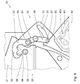
- Fig. 1 shows a side view, with the cutting unit 10 is in a maintenance position
- Fig. 2 shows an enlarged view of a portion of the cutting of Fig. 1 , wherein the switching device 50 of the cutting unit 10 is in the first switching state for enabling the maintenance position.
- the first catch hook 53 is pivoted to a position in which the closer to the whillementschwenkachse A5 latching portion 54 of the first catch hook 53 is at a distance from the first Schneidtechniksschwenkachse A2 with the second bolt 58 is engaged.
- the second cutting part 30 is fixedly connected to the first cutting part 20 and the frame 2.
- the switching device 50 is set up to couple the second cutting mechanism part 30 directly to the first cutting mechanism part 20 at a predetermined distance from the first cutting device pivot axis A2 without pivoting movement tolerance in the first switching state.
- the third cutting member 40 can be pivoted to achieve the second pivot relative to the second cutting member 30.
- the articulation points 40a of the piston-cylinder units 61 are arranged on the third cutting unit part 40 at a relatively short distance from the second cutting unit pivot axis A4, whereby during movement-synchronous extension of the piston-cylinder units 61, a relatively large opening swing angle between the second and third cutting unit parts 30, 40 of at least 70 degrees, in particular at least 80 degrees.
- the third cutting mechanism part 40 is set up such that in the first switching state, the second pivoting, wherein the third cutting mechanism part 40 is pivoted away from the guide element 32 by the bearing device 44 of the cutting blade 42, with the opening swivel angle of at least 70 degrees, in particular at least 80 degrees, is possible.
- Fig. 3 shows an enlarged view of the cutting unit 10, wherein the cutting unit 10 is in a first release position
- Fig. 4 shows an enlarged view of a portion of the cutting unit 10 of Fig. 3 , wherein the switching device 50 of the cutting unit 10 is in the second switching state for enabling the first release position.
- the first fishing hook 53 is pivoted to a position in which the farther from the whillementschwenkachse A5 remote locking portion 55 of the first fishing hook 53 at a distance from the first Schneidtechniksschwenkachse A2 and the second bolt 58 on a through the second pin 58 extending pivot path S2 is arranged with respect to the first cutting unit pivot axis A2, so that the latching portion 55 of the first catch hook 53 with the completion of the first pivoting engages with the second pin 58 engages.
- the second cutting mechanism part 30 is connected to the first cutting mechanism part 20 or the frame 2 only when the first pivoting is completed.
- the switching device 50 is set up to couple the second cutting-work part 30 mechanically directly to the first cutting-part part 20 at a predetermined distance from the first cutting-device pivot axis A2 with pivoting movement tolerance.
- the first pivoting is made possible with such a pivoting movement tolerance that the radial movement of the guide element 32 away from the conveying drum 22 with the second cutting part 30 is limited to a predetermined expansion pivot angle for widening the conveying channel 11.
- the extension swivel angle is less than 10 degrees, in particular about 5 degrees.
- the drive of the first pivoting takes place again via a movement-synchronous extension of the piston-cylinder units 61.
- the switching device 50 is set up to allow the second pivoting in the second switching state such that with respect to a completed first pivoting, the cutting blades 42 can be swiveled out of the cutting position and thus out of the conveying channel 11 by pivoting the bearing device 44 away from the guide element 32.
- the piston-cylinder units 61 continue to move in a synchronized manner until the second pivoting in the second switching state has been completed.
- the first pivoting with the civilsschwenkwinkel is made possible for widening the conveying channel 11, in the case of a stuffer in the conveying channel 11 by its extension of the stuffer can be easily pushed through the conveying channel 11.
- the delivery channel 11 is not fully opened, but is only extended by the extension swivel angle, it is additionally advantageously avoided that crops such as grass fall back onto the field.
- Fig. 5 finally shows an enlarged view of the cutting unit 10, wherein the cutting unit 10 is in a second release position
- Fig. 6 shows an enlarged view of a portion of the cutting of Fig. 5 , wherein the switching device 50 of the cutting unit 10 is in the third switching state for enabling the second release position.
- the second cutting part 30 is fixedly connected to the third cutting part 40.
- the switching device 50 is set up to mechanically couple the second cutting mechanism part 30 directly to the third cutting mechanism part 40 at a predetermined distance from the second cutting mechanism pivot axis A4 without pivoting movement tolerance in the third switching state.
- first catch hook 53 is pivoted to a position such that none of the locking portions 54, 55 is engaged with the second bolt 58 and can enter.
- the second and third cutter parts 30, 40 for achieving the first pivoting can be pivoted together relative to the first cutter part 20.
- the drive of the first pivoting takes place again via a movement synchronous extension of the piston-cylinder units 61 until the conveyor drum 22 and the guide element 32 are completely accessible, so that in addition to performing maintenance on the conveyor drum 22 and the guide element 32 and large in the conveyor channel 11 retracted foreign objects such as fence posts can be removed.
- the switching device 50 may also establish a fourth switching state in which the first pivot and the second pivot are locked. More specifically, for the fourth switching state, the first catch hook 53 is pivotable to the position in which the latching portion 54 of the first catch hook 53 closer to the actuator pivot axis A5 engages with the second bolt 58 at a distance from the first cutter pivot axis A2, and is the first one Bolt 57 movable to the position in which the first bolt 57 is at a distance from the second cutting unit pivot axis A4 with the attached to the third cutting part 40 second fishing hook 59 is engaged. In order to produce the fourth switching state, the two adjusting elements 52, 56 are pivoted about the actuating element pivot axis A5 relative to each other. The fourth switching state can be used advantageously for the normal operation of the cutting unit 10.
- the cutting unit 10 described above provides improved access to its components through the different access variants described above.
Landscapes
- Life Sciences & Earth Sciences (AREA)
- Environmental Sciences (AREA)
- Harvester Elements (AREA)
- Harvesting Machines For Specific Crops (AREA)
Claims (10)
- Tablier de coupe (10) pour une machine de récolte (1), comprenant une première partie de tablier de coupe (20), laquelle comprend un carter (21) et un tambour d'alimentation (22) pour un produit de récolte, qui est disposé dans le carter (21) et monté tournant autour d'un axe de rotation (A1), une deuxième partie de tablier de coupe (30), laquelle comprend un élément de guidage (32) qui s'étend périphériquement le long du tambour d'alimentation (22) de façon à former un canal d'alimentation (11) pour le produit de récolte entre le tambour d'alimentation (22) et l'élément de guidage (32), et laquelle est montée pivotante autour d'un premier axe de pivotement de tablier de coupe (A2) sur la première partie de tablier de coupe (20) de sorte qu'un premier pivotement de la deuxième partie de tablier de coupe (30) permet d'écarter radialement l'élément de guidage (32) du tambour d'alimentation (22), une troisième partie de tablier de coupe (40), laquelle comprend une pluralité de couteaux (42) qui, dans leur position de coupe, s'étendent dans le canal d'alimentation (11) et un dispositif de palier (44) sur lequel les couteaux (42) sont montés, et laquelle est montée pivotante autour d'un deuxième axe de pivotement de tablier de coupe (A4) sur la deuxième partie de tablier de coupe (30) de sorte qu'un deuxième pivotement de la troisième partie de tablier de coupe (40) permet d'écarter le dispositif de palier (44) de l'élément de guidage (32), caractérisé par un dispositif de commutation (50) qui est conçu pour établir sélectivement un premier état de commutation, dans lequel le premier pivotement est bloqué et le deuxième pivotement est rendu possible, un deuxième état de commutation, dans lequel le premier et le deuxième pivotement sont rendus possibles, et un troisième état de commutation, dans lequel le premier pivotement est rendu possible et le deuxième pivotement est bloqué.
- Tablier de coupe (10) selon la revendication 1, comprenant en outre un dispositif d'entraînement (60) qui est couplé à la troisième partie de tablier de coupe (40) de façon qu'un mouvement d'entraînement du dispositif d'entraînement (60) permet d'entraîner aussi bien le premier pivotement que le deuxième pivotement.
- Tablier de coupe (10) selon la revendication 1 ou 2, dans lequel la troisième partie de tablier de coupe (40) est conçue de façon que, dans le premier état de commutation, le deuxième pivotement, lors duquel la troisième partie de tablier de coupe (40) avec le dispositif de palier (44) des couteaux (42) est écartée de l'élément de guidage (32), est rendu possible avec un angle de pivotement d'ouverture d'au moins 70 degrés.
- Tablier de coupe (10) selon l'une des revendications 1 à 4, dans lequel le dispositif de commutation (50) est conçu pour, dans le deuxième état de commutation, rendre possible le premier pivotement de façon que l'écartement radial de l'élément de guidage (32) du tambour d'alimentation (22) avec la deuxième partie de tablier de coupe (30) soit limité à un angle de pivotement d'élargissement prédéterminé pour élargir le canal d'alimentation (11).
- Tablier de coupe (10) selon la revendication 4, dans lequel l'angle de pivotement d'élargissement prédéterminé est inférieur à 10 degrés.
- Tablier de coupe (10) selon l'une des revendications 1 à 5, dans lequel le dispositif de commutation (50) est conçu pour, dans le deuxième état de commutation, rendre possible le deuxième pivotement de façon que, par rapport à un premier pivotement complet, les couteaux (42) puissent être sortis de la position de coupe et donc du canal d'alimentation (11) par écartement pivotant du dispositif de palier (44) par rapport à l'élément de guidage (32).
- Tablier de coupe (10) selon l'une des revendications 1 à 6, dans lequel le dispositif de commutation (50) est conçu pour, dans le premier état de commutation, coupler mécaniquement directement la deuxième partie de tablier de coupe (30) avec la première partie de tablier de coupe (20) à une distance prédéterminée du premier axe de pivotement de tablier de coupe (A2) sans tolérance de mouvement de pivotement.
- Tablier de coupe (10) selon l'une des revendications 1 à 7, dans lequel le dispositif de commutation (50) est conçu pour, dans le deuxième état de commutation, coupler mécaniquement directement la deuxième partie de tablier de coupe (30) avec la première partie de tablier de coupe (20) à une distance prédéterminée du premier axe de pivotement de tablier de coupe (A2) avec une tolérance de mouvement de pivotement.
- Tablier de coupe (10) selon l'une des revendications 1 à 8, dans lequel le dispositif de commutation (50) est conçu pour, dans le troisième état de commutation, coupler mécaniquement directement la deuxième partie de tablier de coupe (30) avec la troisième partie de tablier de coupe (40) à une distance prédéterminée du deuxième axe de pivotement de tablier de coupe (A4) sans tolérance de mouvement de pivotement.
- Tablier de coupe (10) selon l'une des revendications 1 à 9, dans lequel le dispositif de commutation (50) comprend un dispositif d'arrêt (51) qui est prévu sur la deuxième partie de tablier de coupe (30) et qui comprend un premier crochet d'arrêt (53) et un premier axe (57) qui sont montés mobiles pour réaliser les premier à troisième états de commutation, un deuxième axe (58) qui est prévu sur la première partie de tablier de coupe (20) et un deuxième crochet d'arrêt (59) qui est prévu sur la troisième partie de tablier de coupe (40), le premier crochet d'arrêt (53) étant, pour le premier état de commutation, déplaçable vers une position dans laquelle le premier crochet d'arrêt (53) est en prise avec le deuxième axe (58), le premier crochet d'arrêt (53) étant, pour le deuxième état de commutation, déplaçable vers une position dans laquelle le premier crochet d'arrêt (53) est disposé à distance du deuxième axe (58) sur une trajectoire de pivotement (S2) passant par le deuxième axe (58) par rapport au premier axe de pivotement de tablier de coupe (A2), de sorte que le premier crochet d'arrêt (53) entre en prise avec le deuxième axe (58) à la fin du premier pivotement, et le premier axe (57) étant, pour le troisième état de commutation, déplaçable vers une position dans laquelle le premier axe (57) est en prise avec le deuxième crochet d'arrêt (59).
Applications Claiming Priority (1)
| Application Number | Priority Date | Filing Date | Title |
|---|---|---|---|
| DE102014102394.3A DE102014102394A1 (de) | 2014-02-25 | 2014-02-25 | Schneidwerk für eine Erntemaschine |
Publications (2)
| Publication Number | Publication Date |
|---|---|
| EP2910106A1 EP2910106A1 (fr) | 2015-08-26 |
| EP2910106B1 true EP2910106B1 (fr) | 2016-09-21 |
Family
ID=52468924
Family Applications (1)
| Application Number | Title | Priority Date | Filing Date |
|---|---|---|---|
| EP15154946.6A Active EP2910106B1 (fr) | 2014-02-25 | 2015-02-13 | Barre de coupe pour une moissonneuse |
Country Status (2)
| Country | Link |
|---|---|
| EP (1) | EP2910106B1 (fr) |
| DE (1) | DE102014102394A1 (fr) |
Families Citing this family (3)
| Publication number | Priority date | Publication date | Assignee | Title |
|---|---|---|---|---|
| US11632911B2 (en) * | 2020-02-14 | 2023-04-25 | Cnh Industrial America Llc | Agricultural baler with knife overload mitigating system |
| US12336453B2 (en) * | 2021-12-29 | 2025-06-24 | Cnh Industrial America Llc | Knife insert and retract with independent knife protection of agricultural baler |
| CN119344016A (zh) * | 2024-09-23 | 2025-01-24 | 铁建重工新疆有限公司 | 喂入切碎挂接检修装置及青贮机 |
Family Cites Families (5)
| Publication number | Priority date | Publication date | Assignee | Title |
|---|---|---|---|---|
| DE19607915C2 (de) * | 1996-03-01 | 1999-05-06 | Strautmann & Soehne | Schneivorrichtung für Halm- und Blattgut |
| DE29715951U1 (de) * | 1997-09-05 | 1997-11-06 | Maschinenfabriken Bernard Krone Gmbh, 48480 Spelle | Ladewagen |
| DE19928521A1 (de) * | 1999-06-22 | 2001-01-04 | Lely Welger Maschinenfabrik Gm | Zuführkanal für ein Erntefahrzeug, insbesondere für eine landwirtschaftliche Aufsammelballenpresse |
| EP2540151B1 (fr) | 2011-06-28 | 2013-05-29 | B. Strautmann & Söhne GmbH & Co.KG | Dispositif de coupe divisé pour produits à tiges et feuilles |
| US20130167498A1 (en) * | 2011-12-28 | 2013-07-04 | Agco Corporation | Agricultural implement having knife load responsive infeed cutter |
-
2014
- 2014-02-25 DE DE102014102394.3A patent/DE102014102394A1/de not_active Withdrawn
-
2015
- 2015-02-13 EP EP15154946.6A patent/EP2910106B1/fr active Active
Also Published As
| Publication number | Publication date |
|---|---|
| EP2910106A1 (fr) | 2015-08-26 |
| DE102014102394A1 (de) | 2015-08-27 |
Similar Documents
| Publication | Publication Date | Title |
|---|---|---|
| DE102013007304B4 (de) | Schneidwerk für eine Erntemaschine | |
| DE4302199A1 (de) | Schneidwerk für landwirtschaftliche Erntemaschinen | |
| EP1121012A2 (fr) | Dispositif de coupe pour moissonneuse agricole | |
| DE4021030A1 (de) | Maehtisch fuer erntemaschinen | |
| EP2910105A1 (fr) | Protection contre les surcharges de lame de coupe | |
| EP3628142B1 (fr) | Dispositif de coupe pour un engin d'abattage-façonnage agricole ainsi que procédé de fonctionnement d'un dispositif de coupe | |
| EP2910106B1 (fr) | Barre de coupe pour une moissonneuse | |
| EP0499064B1 (fr) | Machine pour ramasser et presser des produits agricoles récoltés | |
| DE102012112154A1 (de) | Landwirtschaftliche Erntemaschine und Verfahren zum Warten einer solchen Erntemaschine | |
| EP2939521A1 (fr) | Machine agricole | |
| EP4074161B1 (fr) | Machine à récolter le foin pourvue d'élément d'arrêt | |
| DE10012088A1 (de) | Vorrichtung zum Pflücken der Fruchtstände stängeliger Erntegüter | |
| EP3092890B1 (fr) | Barre de coupe de moissonneuse | |
| DE102006056050A1 (de) | Gutführvorrichtung | |
| EP2011383B1 (fr) | Moissonneuse dotée d'un dispositif de coupe | |
| EP2527101B1 (fr) | Réceptacle pour ensemble de coupe | |
| EP2910104B1 (fr) | Dispositif de coupe pour une moissonneuse | |
| EP1588601B1 (fr) | Machine de récolte avec un dispositif de décharge | |
| EP0579594B1 (fr) | Dispositif de coupé pour remorque chargeuse | |
| EP1834517B1 (fr) | Moissonneuse automotrice | |
| DE2328478C3 (de) | Gerät zum Entnehmen von Futterportionen aus Silos | |
| DE19621656C2 (de) | Mähdrescher mit einem aus zwei Schneidwerkshälften bestehenden Schneidwerk | |
| DE19517639C2 (de) | Schneideinrichtung für Großballenpressen | |
| DE102013022387B3 (de) | Schneidwerk für eine Erntemaschine | |
| DE102015008505B4 (de) | Schneidvorrichtung und Erntemaschine |
Legal Events
| Date | Code | Title | Description |
|---|---|---|---|
| PUAI | Public reference made under article 153(3) epc to a published international application that has entered the european phase |
Free format text: ORIGINAL CODE: 0009012 |
|
| AK | Designated contracting states |
Kind code of ref document: A1 Designated state(s): AL AT BE BG CH CY CZ DE DK EE ES FI FR GB GR HR HU IE IS IT LI LT LU LV MC MK MT NL NO PL PT RO RS SE SI SK SM TR |
|
| AX | Request for extension of the european patent |
Extension state: BA ME |
|
| 17P | Request for examination filed |
Effective date: 20160226 |
|
| RBV | Designated contracting states (corrected) |
Designated state(s): AL AT BE BG CH CY CZ DE DK EE ES FI FR GB GR HR HU IE IS IT LI LT LU LV MC MK MT NL NO PL PT RO RS SE SI SK SM TR |
|
| GRAP | Despatch of communication of intention to grant a patent |
Free format text: ORIGINAL CODE: EPIDOSNIGR1 |
|
| GRAJ | Information related to disapproval of communication of intention to grant by the applicant or resumption of examination proceedings by the epo deleted |
Free format text: ORIGINAL CODE: EPIDOSDIGR1 |
|
| GRAP | Despatch of communication of intention to grant a patent |
Free format text: ORIGINAL CODE: EPIDOSNIGR1 |
|
| INTG | Intention to grant announced |
Effective date: 20160609 |
|
| INTG | Intention to grant announced |
Effective date: 20160623 |
|
| INTG | Intention to grant announced |
Effective date: 20160627 |
|
| GRAS | Grant fee paid |
Free format text: ORIGINAL CODE: EPIDOSNIGR3 |
|
| GRAA | (expected) grant |
Free format text: ORIGINAL CODE: 0009210 |
|
| AK | Designated contracting states |
Kind code of ref document: B1 Designated state(s): AL AT BE BG CH CY CZ DE DK EE ES FI FR GB GR HR HU IE IS IT LI LT LU LV MC MK MT NL NO PL PT RO RS SE SI SK SM TR |
|
| REG | Reference to a national code |
Ref country code: GB Ref legal event code: FG4D Free format text: NOT ENGLISH |
|
| REG | Reference to a national code |
Ref country code: CH Ref legal event code: EP |
|
| REG | Reference to a national code |
Ref country code: AT Ref legal event code: REF Ref document number: 830253 Country of ref document: AT Kind code of ref document: T Effective date: 20161015 |
|
| REG | Reference to a national code |
Ref country code: IE Ref legal event code: FG4D Free format text: LANGUAGE OF EP DOCUMENT: GERMAN |
|
| REG | Reference to a national code |
Ref country code: DE Ref legal event code: R096 Ref document number: 502015000167 Country of ref document: DE |
|
| REG | Reference to a national code |
Ref country code: NL Ref legal event code: FP |
|
| REG | Reference to a national code |
Ref country code: LT Ref legal event code: MG4D |
|
| PG25 | Lapsed in a contracting state [announced via postgrant information from national office to epo] |
Ref country code: FI Free format text: LAPSE BECAUSE OF FAILURE TO SUBMIT A TRANSLATION OF THE DESCRIPTION OR TO PAY THE FEE WITHIN THE PRESCRIBED TIME-LIMIT Effective date: 20160921 Ref country code: NO Free format text: LAPSE BECAUSE OF FAILURE TO SUBMIT A TRANSLATION OF THE DESCRIPTION OR TO PAY THE FEE WITHIN THE PRESCRIBED TIME-LIMIT Effective date: 20161221 Ref country code: RS Free format text: LAPSE BECAUSE OF FAILURE TO SUBMIT A TRANSLATION OF THE DESCRIPTION OR TO PAY THE FEE WITHIN THE PRESCRIBED TIME-LIMIT Effective date: 20160921 Ref country code: LT Free format text: LAPSE BECAUSE OF FAILURE TO SUBMIT A TRANSLATION OF THE DESCRIPTION OR TO PAY THE FEE WITHIN THE PRESCRIBED TIME-LIMIT Effective date: 20160921 |
|
| PG25 | Lapsed in a contracting state [announced via postgrant information from national office to epo] |
Ref country code: GR Free format text: LAPSE BECAUSE OF FAILURE TO SUBMIT A TRANSLATION OF THE DESCRIPTION OR TO PAY THE FEE WITHIN THE PRESCRIBED TIME-LIMIT Effective date: 20161222 Ref country code: LV Free format text: LAPSE BECAUSE OF FAILURE TO SUBMIT A TRANSLATION OF THE DESCRIPTION OR TO PAY THE FEE WITHIN THE PRESCRIBED TIME-LIMIT Effective date: 20160921 Ref country code: SE Free format text: LAPSE BECAUSE OF FAILURE TO SUBMIT A TRANSLATION OF THE DESCRIPTION OR TO PAY THE FEE WITHIN THE PRESCRIBED TIME-LIMIT Effective date: 20160921 |
|
| PG25 | Lapsed in a contracting state [announced via postgrant information from national office to epo] |
Ref country code: EE Free format text: LAPSE BECAUSE OF FAILURE TO SUBMIT A TRANSLATION OF THE DESCRIPTION OR TO PAY THE FEE WITHIN THE PRESCRIBED TIME-LIMIT Effective date: 20160921 Ref country code: RO Free format text: LAPSE BECAUSE OF FAILURE TO SUBMIT A TRANSLATION OF THE DESCRIPTION OR TO PAY THE FEE WITHIN THE PRESCRIBED TIME-LIMIT Effective date: 20160921 |
|
| PG25 | Lapsed in a contracting state [announced via postgrant information from national office to epo] |
Ref country code: PT Free format text: LAPSE BECAUSE OF FAILURE TO SUBMIT A TRANSLATION OF THE DESCRIPTION OR TO PAY THE FEE WITHIN THE PRESCRIBED TIME-LIMIT Effective date: 20170123 Ref country code: CZ Free format text: LAPSE BECAUSE OF FAILURE TO SUBMIT A TRANSLATION OF THE DESCRIPTION OR TO PAY THE FEE WITHIN THE PRESCRIBED TIME-LIMIT Effective date: 20160921 Ref country code: SM Free format text: LAPSE BECAUSE OF FAILURE TO SUBMIT A TRANSLATION OF THE DESCRIPTION OR TO PAY THE FEE WITHIN THE PRESCRIBED TIME-LIMIT Effective date: 20160921 Ref country code: IS Free format text: LAPSE BECAUSE OF FAILURE TO SUBMIT A TRANSLATION OF THE DESCRIPTION OR TO PAY THE FEE WITHIN THE PRESCRIBED TIME-LIMIT Effective date: 20170121 Ref country code: PL Free format text: LAPSE BECAUSE OF FAILURE TO SUBMIT A TRANSLATION OF THE DESCRIPTION OR TO PAY THE FEE WITHIN THE PRESCRIBED TIME-LIMIT Effective date: 20160921 Ref country code: BE Free format text: LAPSE BECAUSE OF NON-PAYMENT OF DUE FEES Effective date: 20170228 Ref country code: SK Free format text: LAPSE BECAUSE OF FAILURE TO SUBMIT A TRANSLATION OF THE DESCRIPTION OR TO PAY THE FEE WITHIN THE PRESCRIBED TIME-LIMIT Effective date: 20160921 Ref country code: BG Free format text: LAPSE BECAUSE OF FAILURE TO SUBMIT A TRANSLATION OF THE DESCRIPTION OR TO PAY THE FEE WITHIN THE PRESCRIBED TIME-LIMIT Effective date: 20161221 Ref country code: ES Free format text: LAPSE BECAUSE OF FAILURE TO SUBMIT A TRANSLATION OF THE DESCRIPTION OR TO PAY THE FEE WITHIN THE PRESCRIBED TIME-LIMIT Effective date: 20160921 |
|
| REG | Reference to a national code |
Ref country code: DE Ref legal event code: R097 Ref document number: 502015000167 Country of ref document: DE |
|
| PG25 | Lapsed in a contracting state [announced via postgrant information from national office to epo] |
Ref country code: IT Free format text: LAPSE BECAUSE OF FAILURE TO SUBMIT A TRANSLATION OF THE DESCRIPTION OR TO PAY THE FEE WITHIN THE PRESCRIBED TIME-LIMIT Effective date: 20160921 |
|
| PLBE | No opposition filed within time limit |
Free format text: ORIGINAL CODE: 0009261 |
|
| STAA | Information on the status of an ep patent application or granted ep patent |
Free format text: STATUS: NO OPPOSITION FILED WITHIN TIME LIMIT |
|
| PG25 | Lapsed in a contracting state [announced via postgrant information from national office to epo] |
Ref country code: DK Free format text: LAPSE BECAUSE OF FAILURE TO SUBMIT A TRANSLATION OF THE DESCRIPTION OR TO PAY THE FEE WITHIN THE PRESCRIBED TIME-LIMIT Effective date: 20160921 |
|
| 26N | No opposition filed |
Effective date: 20170622 |
|
| PG25 | Lapsed in a contracting state [announced via postgrant information from national office to epo] |
Ref country code: MC Free format text: LAPSE BECAUSE OF FAILURE TO SUBMIT A TRANSLATION OF THE DESCRIPTION OR TO PAY THE FEE WITHIN THE PRESCRIBED TIME-LIMIT Effective date: 20160921 |
|
| REG | Reference to a national code |
Ref country code: IE Ref legal event code: MM4A |
|
| PG25 | Lapsed in a contracting state [announced via postgrant information from national office to epo] |
Ref country code: SI Free format text: LAPSE BECAUSE OF FAILURE TO SUBMIT A TRANSLATION OF THE DESCRIPTION OR TO PAY THE FEE WITHIN THE PRESCRIBED TIME-LIMIT Effective date: 20160921 |
|
| REG | Reference to a national code |
Ref country code: FR Ref legal event code: ST Effective date: 20171031 |
|
| PG25 | Lapsed in a contracting state [announced via postgrant information from national office to epo] |
Ref country code: LU Free format text: LAPSE BECAUSE OF NON-PAYMENT OF DUE FEES Effective date: 20170213 |
|
| PG25 | Lapsed in a contracting state [announced via postgrant information from national office to epo] |
Ref country code: FR Free format text: LAPSE BECAUSE OF NON-PAYMENT OF DUE FEES Effective date: 20170228 |
|
| REG | Reference to a national code |
Ref country code: BE Ref legal event code: MM Effective date: 20170228 |
|
| PG25 | Lapsed in a contracting state [announced via postgrant information from national office to epo] |
Ref country code: IE Free format text: LAPSE BECAUSE OF NON-PAYMENT OF DUE FEES Effective date: 20170213 |
|
| REG | Reference to a national code |
Ref country code: CH Ref legal event code: PL |
|
| PG25 | Lapsed in a contracting state [announced via postgrant information from national office to epo] |
Ref country code: MT Free format text: LAPSE BECAUSE OF FAILURE TO SUBMIT A TRANSLATION OF THE DESCRIPTION OR TO PAY THE FEE WITHIN THE PRESCRIBED TIME-LIMIT Effective date: 20160921 |
|
| REG | Reference to a national code |
Ref country code: NL Ref legal event code: MM Effective date: 20180301 |
|
| PG25 | Lapsed in a contracting state [announced via postgrant information from national office to epo] |
Ref country code: AL Free format text: LAPSE BECAUSE OF FAILURE TO SUBMIT A TRANSLATION OF THE DESCRIPTION OR TO PAY THE FEE WITHIN THE PRESCRIBED TIME-LIMIT Effective date: 20160921 |
|
| PG25 | Lapsed in a contracting state [announced via postgrant information from national office to epo] |
Ref country code: CH Free format text: LAPSE BECAUSE OF NON-PAYMENT OF DUE FEES Effective date: 20180228 Ref country code: LI Free format text: LAPSE BECAUSE OF NON-PAYMENT OF DUE FEES Effective date: 20180228 |
|
| PG25 | Lapsed in a contracting state [announced via postgrant information from national office to epo] |
Ref country code: NL Free format text: LAPSE BECAUSE OF NON-PAYMENT OF DUE FEES Effective date: 20180301 |
|
| REG | Reference to a national code |
Ref country code: NL Ref legal event code: NE Effective date: 20190429 |
|
| PG25 | Lapsed in a contracting state [announced via postgrant information from national office to epo] |
Ref country code: HU Free format text: LAPSE BECAUSE OF FAILURE TO SUBMIT A TRANSLATION OF THE DESCRIPTION OR TO PAY THE FEE WITHIN THE PRESCRIBED TIME-LIMIT; INVALID AB INITIO Effective date: 20150213 |
|
| REG | Reference to a national code |
Ref country code: NL Ref legal event code: NF Effective date: 20190821 |
|
| PG25 | Lapsed in a contracting state [announced via postgrant information from national office to epo] |
Ref country code: NL Free format text: LAPSE BECAUSE OF NON-PAYMENT OF DUE FEES Effective date: 20180301 |
|
| PGRI | Patent reinstated in contracting state [announced from national office to epo] |
Ref country code: NL Effective date: 20190821 |
|
| GBPC | Gb: european patent ceased through non-payment of renewal fee |
Effective date: 20190213 |
|
| PG25 | Lapsed in a contracting state [announced via postgrant information from national office to epo] |
Ref country code: CY Free format text: LAPSE BECAUSE OF FAILURE TO SUBMIT A TRANSLATION OF THE DESCRIPTION OR TO PAY THE FEE WITHIN THE PRESCRIBED TIME-LIMIT Effective date: 20160921 |
|
| PG25 | Lapsed in a contracting state [announced via postgrant information from national office to epo] |
Ref country code: MK Free format text: LAPSE BECAUSE OF FAILURE TO SUBMIT A TRANSLATION OF THE DESCRIPTION OR TO PAY THE FEE WITHIN THE PRESCRIBED TIME-LIMIT Effective date: 20160921 |
|
| PG25 | Lapsed in a contracting state [announced via postgrant information from national office to epo] |
Ref country code: GB Free format text: LAPSE BECAUSE OF NON-PAYMENT OF DUE FEES Effective date: 20190213 |
|
| PG25 | Lapsed in a contracting state [announced via postgrant information from national office to epo] |
Ref country code: TR Free format text: LAPSE BECAUSE OF FAILURE TO SUBMIT A TRANSLATION OF THE DESCRIPTION OR TO PAY THE FEE WITHIN THE PRESCRIBED TIME-LIMIT Effective date: 20160921 |
|
| PG25 | Lapsed in a contracting state [announced via postgrant information from national office to epo] |
Ref country code: HR Free format text: LAPSE BECAUSE OF FAILURE TO SUBMIT A TRANSLATION OF THE DESCRIPTION OR TO PAY THE FEE WITHIN THE PRESCRIBED TIME-LIMIT Effective date: 20160921 |
|
| P01 | Opt-out of the competence of the unified patent court (upc) registered |
Effective date: 20230509 |
|
| PGFP | Annual fee paid to national office [announced via postgrant information from national office to epo] |
Ref country code: NL Payment date: 20260218 Year of fee payment: 12 |
|
| PGFP | Annual fee paid to national office [announced via postgrant information from national office to epo] |
Ref country code: DE Payment date: 20260218 Year of fee payment: 12 |
|
| PGFP | Annual fee paid to national office [announced via postgrant information from national office to epo] |
Ref country code: AT Payment date: 20260219 Year of fee payment: 12 |