EP2910864B1 - Unité de refroidissement d'eau pour des systèmes de conditionnement - Google Patents
Unité de refroidissement d'eau pour des systèmes de conditionnement Download PDFInfo
- Publication number
- EP2910864B1 EP2910864B1 EP15155733.7A EP15155733A EP2910864B1 EP 2910864 B1 EP2910864 B1 EP 2910864B1 EP 15155733 A EP15155733 A EP 15155733A EP 2910864 B1 EP2910864 B1 EP 2910864B1
- Authority
- EP
- European Patent Office
- Prior art keywords
- batteries
- air
- freecooling
- battery
- evaporator
- Prior art date
- Legal status (The legal status is an assumption and is not a legal conclusion. Google has not performed a legal analysis and makes no representation as to the accuracy of the status listed.)
- Active
Links
Images


Classifications
-
- F—MECHANICAL ENGINEERING; LIGHTING; HEATING; WEAPONS; BLASTING
- F24—HEATING; RANGES; VENTILATING
- F24F—AIR-CONDITIONING; AIR-HUMIDIFICATION; VENTILATION; USE OF AIR CURRENTS FOR SCREENING
- F24F5/00—Air-conditioning systems or apparatus not covered by F24F1/00 or F24F3/00, e.g. using solar heat or combined with household units such as an oven or water heater
- F24F5/0007—Air-conditioning systems or apparatus not covered by F24F1/00 or F24F3/00, e.g. using solar heat or combined with household units such as an oven or water heater cooling apparatus specially adapted for use in air-conditioning
- F24F5/0035—Air-conditioning systems or apparatus not covered by F24F1/00 or F24F3/00, e.g. using solar heat or combined with household units such as an oven or water heater cooling apparatus specially adapted for use in air-conditioning using evaporation
-
- F—MECHANICAL ENGINEERING; LIGHTING; HEATING; WEAPONS; BLASTING
- F24—HEATING; RANGES; VENTILATING
- F24F—AIR-CONDITIONING; AIR-HUMIDIFICATION; VENTILATION; USE OF AIR CURRENTS FOR SCREENING
- F24F1/00—Room units for air-conditioning, e.g. separate or self-contained units or units receiving primary air from a central station
- F24F1/06—Separate outdoor units, e.g. outdoor unit to be linked to a separate room comprising a compressor and a heat exchanger
- F24F1/46—Component arrangements in separate outdoor units
-
- F—MECHANICAL ENGINEERING; LIGHTING; HEATING; WEAPONS; BLASTING
- F24—HEATING; RANGES; VENTILATING
- F24F—AIR-CONDITIONING; AIR-HUMIDIFICATION; VENTILATION; USE OF AIR CURRENTS FOR SCREENING
- F24F5/00—Air-conditioning systems or apparatus not covered by F24F1/00 or F24F3/00, e.g. using solar heat or combined with household units such as an oven or water heater
- F24F5/0007—Air-conditioning systems or apparatus not covered by F24F1/00 or F24F3/00, e.g. using solar heat or combined with household units such as an oven or water heater cooling apparatus specially adapted for use in air-conditioning
- F24F5/001—Compression cycle type
-
- F—MECHANICAL ENGINEERING; LIGHTING; HEATING; WEAPONS; BLASTING
- F25—REFRIGERATION OR COOLING; COMBINED HEATING AND REFRIGERATION SYSTEMS; HEAT PUMP SYSTEMS; MANUFACTURE OR STORAGE OF ICE; LIQUEFACTION SOLIDIFICATION OF GASES
- F25B—REFRIGERATION MACHINES, PLANTS OR SYSTEMS; COMBINED HEATING AND REFRIGERATION SYSTEMS; HEAT PUMP SYSTEMS
- F25B25/00—Machines, plants or systems, using a combination of modes of operation covered by two or more of the groups F25B1/00 - F25B23/00
- F25B25/005—Machines, plants or systems, using a combination of modes of operation covered by two or more of the groups F25B1/00 - F25B23/00 using primary and secondary systems
-
- Y—GENERAL TAGGING OF NEW TECHNOLOGICAL DEVELOPMENTS; GENERAL TAGGING OF CROSS-SECTIONAL TECHNOLOGIES SPANNING OVER SEVERAL SECTIONS OF THE IPC; TECHNICAL SUBJECTS COVERED BY FORMER USPC CROSS-REFERENCE ART COLLECTIONS [XRACs] AND DIGESTS
- Y02—TECHNOLOGIES OR APPLICATIONS FOR MITIGATION OR ADAPTATION AGAINST CLIMATE CHANGE
- Y02B—CLIMATE CHANGE MITIGATION TECHNOLOGIES RELATED TO BUILDINGS, e.g. HOUSING, HOUSE APPLIANCES OR RELATED END-USER APPLICATIONS
- Y02B30/00—Energy efficient heating, ventilation or air conditioning [HVAC]
- Y02B30/54—Free-cooling systems
Definitions
- the present invention relates to a system comprising a water cooling unit and an air-conditioning system.
- conditioning units that use refrigerated water (fan coils)
- these conditioning units are supplied with a transfer fluid, typically water or water with the addition of glycol, which circulates from liquid refrigeration machines, of the so-called “chiller” type, i.e., water cooling unit.
- the hydraulic systems for these cooling machines have, on a same line, pumping means adapted to propel a transfer fluid through an exchanger for cooling the transfer fluid, which is none other than the evaporator of an associated water cooling refrigeration system.
- a similar type of system also has a free cooling device, known in the jargon as "freecooling", for said transfer fluid.
- This free cooling device has the limitation that it is effective only in the presence of specific external climate conditions, i.e., only if the external air is cool enough to be able to refrigerate, in an adapted exchange battery, the water that is intended to enter the evaporator.
- Patent document JP-A-2013-119989 describes a combined device according to the preamble of claim 1.
- the aim of the present invention is to provide a system that is capable of obviating the cited limitations of the background art.
- an object of the invention is to provide a system that is simple and economical, particularly as regards consumption.
- a water cooling unit comprised in the invention is designated generally by the reference numeral 10.
- the cooling unit 10 comprises, within a box-like container 11:
- FIG. 10 A simplified diagram of the device 10 is shown clearly in Figure 1 .
- the numeral 50 designates a compressor of a refrigeration circuit 51.
- a first embodiment of the system according to the invention which is to be understood as a nonlimiting example of the invention, shown schematically in Figure 2 , there are, symmetrical with respect to the first ones, a second air precooling panel 23, with corresponding associated cooling means 24, and a corresponding second pair 25 of heat exchange batteries, a first battery 26 for freecooling of the water that enters the evaporator 18 of the air-conditioning system 19, and the second battery 27 is for condensation for the evaporator 18.
- Two additional symmetrical pairs of batteries, 28 and 29 respectively, are also present and are arranged so as to be inclined in a central position between the two pairs of batteries, the first one 15 and the second one 25, which are instead arranged vertically; each one of the third and fourth pairs of batteries 28 and 29 has a corresponding first battery 30 and 31 that is directed downwardly and a second battery 32 and 33 that is directed upwardly; the pairs of batteries 28 and 29 are adapted to affect a stream of rising pre-cooled external air 35, which also arrives from the precooling panel 12 or 23.
- Each air precooling panel for example 12 but also 23, comprises a honeycomb panel, the cells of which are open in the air passage direction.
- the means 13 and 24 for cooling the stream of external air that passes through the precooling panel 12 and 23 are constituted by
- the upper dispenser 36 can be constituted for example by a spray head of the shower type, which is substantially as long as the precooling panel 12 and 23.
- the upper dispenser 36 can also be of another type, depending on the requirements and technical needs.
- the first and second pairs of batteries 15 and 25, which are vertical, are struck directly by the stream of pre-cooled air 20.
- the means 21 for exit out of the box-like container 11 for the heated air 22 that exits from the pairs of laterally adjacent heat exchange batteries comprise ventilation means, for example a series of fans 40, which are arranged in the upper part of the boxlike container 11 and determine the movement of the air from the outside and through the pre-cooling panels and then through the pairs of batteries.
- the heated air 22 is emitted through corresponding grilles above the box-like body 11.
- the first means for hydraulic connection between the water return 43 of the air-conditioning system 19 and the water inlet 44 of the freecooling batteries 16, 26, 30 and 31 comprise a series of ducts with nodes and branches adapted to supply in parallel all the freecooling heat exchange batteries 16, 26, 30 and 31.
- the second means for hydraulic connection between the freecooling batteries 16, 26, 30 and 31 and the evaporator 18 likewise comprise a series of ducts with connectors adapted to convey in parallel the cooled water that exits from all the freecooling heat exchange batteries 16, 26, 30 and 31 toward the single duct 46 that enters the evaporator 18.
- the evaporator 18 is arranged within the box-like container 11, but it is to be understood that a constructive variation of the cooling unit 10 according to the invention in which the evaporator 18 is external with respect to the box-like container 11 is equally equivalent.
- cooling of the external air occurs by way of the evaporation of the water that descends on the precooling panel 12 and 23.
- Heat exchange occurs in the honeycomb panel.
- the air is thus cooled.
- FIGS 3 and 4 show the cooling unit of a second embodiment of the system according to the invention, designated therein by the reference numeral 110.
- the cooling unit 110 comprises, within a box-like container 111:
- the V-shaped configuration of the arrangement of the pairs of batteries refer to a configuration that can be shown schematically in a side view, as in Figure 4 .
- the individual pairs of batteries 115, 115a, 115b, 115c are extended transversely to the box-like container 111 so as to occupy it almost entirely, or entirely, over its width, as clearly exemplified in Figure 3 .
- the means 113 for cooling the external air stream that passes through the precooling panel 112 are shown schematically in Figure 3 and comprise, as described above for the first embodiment:
- Figure 5 shows schematically the hydraulic circuit 160 for cooling the water intended for a conditioning system 119.
- the first means for hydraulic connection between the water return 143 of the air-conditioning system 119 and the water inlet 144 of the freecooling batteries 116 and 116a in the figure, designated as freecooling battery assembly 161, comprise a series of ducts with nodes and branches adapted to supply in parallel all the freecooling heat exchange batteries 116 and 116a.
- the second means for hydraulic connection between the assembly 161 of freecooling batteries 116 and 116a and the evaporator 118 likewise comprise a series of ducts with connectors adapted to convey the cooled air that exits from the assembly 161 of heat exchange batteries for freecooling 116, 116a toward the single duct 146 that enters the evaporator 118.
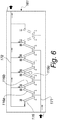
- Figure 6 shows schematically the assembly 161 of freecooling batteries 116, 116a, 116b, 116c.
- the freecooling batteries 116, 116a, 116b, 116c are connected in parallel, with a single loading duct 171 and a single output duct 172, between which the freecooling batteries are connected in parallel, conveniently arranged in pairs in front of each other so as to define a V-shaped mutual arrangement in a side view.
- the invention provides a device for optimizing the efficiency of a water cooling system that is simple and economical, both in terms of structure and in terms of consumption, since the precooling of the external air occurs by simple air-water heat exchange with evaporation of the latter.
- the invention provides a device for optimizing the efficiency of a water cooling system that has a reduced environmental impact with respect to the background art, since there is no resort to additional compressors or other electrically costly components.
- the materials used may be any according to requirements and to the state of the art.
Landscapes
- Engineering & Computer Science (AREA)
- Mechanical Engineering (AREA)
- General Engineering & Computer Science (AREA)
- Chemical & Material Sciences (AREA)
- Combustion & Propulsion (AREA)
- Life Sciences & Earth Sciences (AREA)
- Sustainable Development (AREA)
- Physics & Mathematics (AREA)
- Thermal Sciences (AREA)
- Secondary Cells (AREA)
Claims (7)
- Système comportant :- une unité de refroidissement d'eau (10), un système de conditionnement d'air (19) et un contenant analogue à un boîtier (11), l'unité de refroidissement d'eau (10) étant agencée à l'intérieur dudit contenant analogue à un boîtier (11),- un panneau de pré-refroidissement d'air (12), pourvu d'une matrice de trous traversants, et associé à des moyens (13) configurés pour refroidir un flux d'air externe (14) qui passe à travers ladite matrice de trous,- au moins une paire (15) de batteries d'échange de chaleur latéralement adjacentes (16, 17),- un évaporateur (18) ayant un condenseur (17),- un circuit de réfrigération (51) ayant un compresseur (50), ledit circuit de réfrigération (51) étant un circuit de réfrigération fermé s'étendant à travers ladite seconde batterie (17), ledit évaporateur (18) et ledit compresseur (50),- des moyens (21) configurés pour fournir une sortie à l'extérieur du contenant analogue à un boîtier (11) de l'air chauffé (22) qui sort de ladite au moins une paire (15) de batteries d'échange de chaleur latéralement adjacentes,dans lequel pour chaque paire de batteries latéralement adjacentes, la première batterie (16) est configurée pour assurer un refroidissement naturel de l'eau entrant dans ledit évaporateur (18) et la seconde batterie (17) est une batterie de condensation dudit condenseur de l'évaporateur (18), le système étant caractérisé en ce que l'unité (10) comporte en outre :- des premiers moyens configurés pour assurer une liaison hydraulique entre le retour d'eau (43) dudit système de conditionnement d'air (19) et l'entrée d'eau (44) de ladite au moins une batterie de refroidissement naturel (16), et- des seconds moyens configurés pour assurer une liaison hydraulique entre ladite au moins une batterie de refroidissement naturel (16) et ledit évaporateur (18).
- Système selon la revendication 1, caractérisé en ce que ledit panneau de pré-refroidissement d'air (12) comporte un panneau en nid d'abeille dont les cellules sont ouvertes dans la direction de passage de l'air.
- Système selon une ou plusieurs des revendications précédentes, caractérisé en ce que lesdits moyens (13) pour refroidir le flux d'air externe (14) qui passe à travers ledit panneau de pré-refroidissement sont constitués de :- un distributeur d'eau supérieur (36), adapté pour mouiller ledit panneau en nid d'abeille vers le bas à partir du dessus,- un récipient de collecte inférieur (37),- une pompe de recirculation (38) pour la montée de l'eau de pré-refroidissement d'air depuis ledit récipient inférieur (37) jusqu'audit distributeur supérieur (36).
- Système selon une ou plusieurs des revendications précédentes, caractérisé en ce qu'il comporte, à l'intérieur du contenant analogue à un boîtier (11, 111) :- deux panneaux de pré-refroidissement d'air (112) opposés, agencés de manière à affecter les faces latérales du contenant analogue à un boîtier (111) pratiquement sur toute sa longueur, chaque panneau de pré-refroidissement (112) étant pourvu d'une matrice de trous traversants et étant associé à des moyens (113) pour refroidir un flux d'air externe (104) qui s'écoule à travers ladite matrice de trous,- une série de paires (115, 115a, 115b, 115c) de batteries d'échange de chaleur latéralement adjacentes,- parmi chaque paire (115, 115a, 115b, 115c) de batteries latéralement adjacentes, une première batterie (116) est destinée au refroidissement naturel de l'eau en entrée d'un évaporateur (118) et la seconde batterie (117) est une batterie de condensation pour l'évaporateur (118),- des moyens (121) pour la sortie à l'extérieur du contenant analogue à un boîtier (111) de l'air chauffé (122) qui sort de chaque paire (115) de batteries d'échange de chaleur latéralement adjacentes,- des premiers moyens pour une liaison hydraulique entre le retour d'eau à partir d'un système de conditionnement d'air (119) et l'entrée d'eau des premières batteries de refroidissement naturel (116), et- des seconds moyens pour une liaison hydraulique entre les premières batteries de refroidissement naturel (116) et ledit évaporateur (118).
- Système selon la revendication 4, caractérisé en ce que lesdites paires de batteries d'échange de chaleur (115, 115a, 115b, 115c) sont agencées deux par deux de manière à être l'une en face de l'autre dans la direction de la longueur du contenant analogue à un boîtier (111), et sont agencées, de nouveau deux par deux, de manière à définir une configuration en forme de V, par exemple des premières paires (115, 115a) et des secondes paires (115b, 115c) de batteries.
- Système selon une ou plusieurs des revendications précédentes, caractérisé en ce que les paires individuelles de batteries (15, 115, 115a, 115b, 115c) s'étendent transversalement au contenant analogue à un boîtier (11, 111) de manière à l'occuper pratiquement entièrement ou entièrement sur sa largeur.
- Système selon une ou plusieurs des revendications précédentes, caractérisé en ce que les batteries de refroidissement naturel (116, 116a, 116b, 116c) d'un groupe de batteries de refroidissement naturel (161) sont raccordées en parallèle, avec une seule conduite de charge (171) et une seule conduite de sortie (172), entre lesquelles lesdites batteries de refroidissement naturel (116, 116a, 116b, 116c) sont raccordées en parallèle.
Applications Claiming Priority (1)
| Application Number | Priority Date | Filing Date | Title |
|---|---|---|---|
| ITPD20140037 | 2014-02-21 |
Publications (2)
| Publication Number | Publication Date |
|---|---|
| EP2910864A1 EP2910864A1 (fr) | 2015-08-26 |
| EP2910864B1 true EP2910864B1 (fr) | 2021-04-21 |
Family
ID=50624988
Family Applications (1)
| Application Number | Title | Priority Date | Filing Date |
|---|---|---|---|
| EP15155733.7A Active EP2910864B1 (fr) | 2014-02-21 | 2015-02-19 | Unité de refroidissement d'eau pour des systèmes de conditionnement |
Country Status (3)
| Country | Link |
|---|---|
| US (1) | US20150241073A1 (fr) |
| EP (1) | EP2910864B1 (fr) |
| ES (1) | ES2880445T3 (fr) |
Families Citing this family (3)
| Publication number | Priority date | Publication date | Assignee | Title |
|---|---|---|---|---|
| SG10202107907YA (en) | 2016-03-16 | 2021-08-30 | Inertech Ip Llc | System and methods utilizing fluid coolers and chillers to perform in-series heat rejection and trim cooling |
| CN106322599A (zh) * | 2016-08-30 | 2017-01-11 | 哈尔滨研拓科技发展有限公司 | 冷凝水自处理机柜空调 |
| CN107327994A (zh) * | 2017-07-10 | 2017-11-07 | 江苏省邮电规划设计院有限责任公司 | 一种风冷型带蒸发冷却功能的热管空调机组 |
Family Cites Families (3)
| Publication number | Priority date | Publication date | Assignee | Title |
|---|---|---|---|---|
| US4567733A (en) * | 1983-10-05 | 1986-02-04 | Hiross, Inc. | Economizing air conditioning system of increased efficiency of heat transfer selectively from liquid coolant or refrigerant to air |
| IT1317633B1 (it) * | 2000-03-16 | 2003-07-15 | Rc Group Spa | Gruppo refrigeratore con free-cooling, atto a funzionare anche conportaata variabile, impianto e procedimento. |
| JP2013119989A (ja) * | 2011-12-07 | 2013-06-17 | Orion Machinery Co Ltd | フリークーリングチラー |
-
2015
- 2015-02-19 EP EP15155733.7A patent/EP2910864B1/fr active Active
- 2015-02-19 ES ES15155733T patent/ES2880445T3/es active Active
- 2015-02-20 US US14/627,490 patent/US20150241073A1/en not_active Abandoned
Non-Patent Citations (1)
| Title |
|---|
| None * |
Also Published As
| Publication number | Publication date |
|---|---|
| US20150241073A1 (en) | 2015-08-27 |
| EP2910864A1 (fr) | 2015-08-26 |
| ES2880445T3 (es) | 2021-11-24 |
Similar Documents
| Publication | Publication Date | Title |
|---|---|---|
| US10072883B2 (en) | Heat source unit | |
| CN105283719B (zh) | 冷冻装置的除霜系统以及冷却单元 | |
| RU2660812C2 (ru) | Теплообменник для охлаждения электрошкафа и соответствующая охлаждающая структура | |
| US10161658B2 (en) | Modular coil for air cooled chillers | |
| EP3607252B1 (fr) | Système de refroidissement avec un module économiseur et procédé de fonctionnement d'un tel système | |
| US9933171B2 (en) | Air conditioning and heat pump system with evaporative cooling system | |
| EP2910864B1 (fr) | Unité de refroidissement d'eau pour des systèmes de conditionnement | |
| JP6292834B2 (ja) | 情報処理室の空調設備 | |
| CN102759213A (zh) | 水冷或风水冷两用型制冷系统 | |
| CN104154695A (zh) | 一种冷水机组 | |
| KR100805247B1 (ko) | 수냉 히트 펌프식 공조기 | |
| KR102061757B1 (ko) | 모듈형 하이브리드 실외기 장치 | |
| KR20200061222A (ko) | 제빙기용 응축기 및 이를 이용한 제빙기 | |
| CN208967952U (zh) | 一种数据中心使用的蒸发冷高效冷水机组 | |
| KR102054306B1 (ko) | 하이브리드 공기조화 시스템 | |
| US12018866B2 (en) | Central air conditioning and heat pump system with cooling arrangement | |
| US20180320950A1 (en) | Freezer with Evaporative Condensing Arrangement | |
| KR101268055B1 (ko) | 산업용 칠러 | |
| CN203893544U (zh) | 柜式分体机 | |
| KR20140059007A (ko) | 공조 냉장 복합 시스템 | |
| US10398064B2 (en) | Cooling arrangement for air conditioning an it environment and especially for climate control in a data processing center | |
| EP2865984B1 (fr) | Méthode pour le lavage de deux batteries d'échange de chaleur placées côte à côte | |
| CN106524618B (zh) | 一种室内多功能造雪机 | |
| JP2016180574A (ja) | 空調装置 | |
| CN108507095A (zh) | 一种数据中心使用的蒸发冷高效冷水机组 |
Legal Events
| Date | Code | Title | Description |
|---|---|---|---|
| PUAI | Public reference made under article 153(3) epc to a published international application that has entered the european phase |
Free format text: ORIGINAL CODE: 0009012 |
|
| AK | Designated contracting states |
Kind code of ref document: A1 Designated state(s): AL AT BE BG CH CY CZ DE DK EE ES FI FR GB GR HR HU IE IS IT LI LT LU LV MC MK MT NL NO PL PT RO RS SE SI SK SM TR |
|
| AX | Request for extension of the european patent |
Extension state: BA ME |
|
| 17P | Request for examination filed |
Effective date: 20160225 |
|
| RBV | Designated contracting states (corrected) |
Designated state(s): AL AT BE BG CH CY CZ DE DK EE ES FI FR GB GR HR HU IE IS IT LI LT LU LV MC MK MT NL NO PL PT RO RS SE SI SK SM TR |
|
| RAP1 | Party data changed (applicant data changed or rights of an application transferred) |
Owner name: VERTIV S.R.L. |
|
| STAA | Information on the status of an ep patent application or granted ep patent |
Free format text: STATUS: EXAMINATION IS IN PROGRESS |
|
| 17Q | First examination report despatched |
Effective date: 20200130 |
|
| GRAP | Despatch of communication of intention to grant a patent |
Free format text: ORIGINAL CODE: EPIDOSNIGR1 |
|
| STAA | Information on the status of an ep patent application or granted ep patent |
Free format text: STATUS: GRANT OF PATENT IS INTENDED |
|
| INTG | Intention to grant announced |
Effective date: 20201110 |
|
| GRAS | Grant fee paid |
Free format text: ORIGINAL CODE: EPIDOSNIGR3 |
|
| GRAA | (expected) grant |
Free format text: ORIGINAL CODE: 0009210 |
|
| STAA | Information on the status of an ep patent application or granted ep patent |
Free format text: STATUS: THE PATENT HAS BEEN GRANTED |
|
| AK | Designated contracting states |
Kind code of ref document: B1 Designated state(s): AL AT BE BG CH CY CZ DE DK EE ES FI FR GB GR HR HU IE IS IT LI LT LU LV MC MK MT NL NO PL PT RO RS SE SI SK SM TR |
|
| REG | Reference to a national code |
Ref country code: GB Ref legal event code: FG4D |
|
| REG | Reference to a national code |
Ref country code: CH Ref legal event code: EP |
|
| REG | Reference to a national code |
Ref country code: DE Ref legal event code: R096 Ref document number: 602015068283 Country of ref document: DE Ref country code: IE Ref legal event code: FG4D |
|
| REG | Reference to a national code |
Ref country code: AT Ref legal event code: REF Ref document number: 1385034 Country of ref document: AT Kind code of ref document: T Effective date: 20210515 |
|
| REG | Reference to a national code |
Ref country code: NL Ref legal event code: FP |
|
| REG | Reference to a national code |
Ref country code: LT Ref legal event code: MG9D |
|
| REG | Reference to a national code |
Ref country code: AT Ref legal event code: MK05 Ref document number: 1385034 Country of ref document: AT Kind code of ref document: T Effective date: 20210421 |
|
| PG25 | Lapsed in a contracting state [announced via postgrant information from national office to epo] |
Ref country code: FI Free format text: LAPSE BECAUSE OF FAILURE TO SUBMIT A TRANSLATION OF THE DESCRIPTION OR TO PAY THE FEE WITHIN THE PRESCRIBED TIME-LIMIT Effective date: 20210421 Ref country code: LT Free format text: LAPSE BECAUSE OF FAILURE TO SUBMIT A TRANSLATION OF THE DESCRIPTION OR TO PAY THE FEE WITHIN THE PRESCRIBED TIME-LIMIT Effective date: 20210421 Ref country code: BG Free format text: LAPSE BECAUSE OF FAILURE TO SUBMIT A TRANSLATION OF THE DESCRIPTION OR TO PAY THE FEE WITHIN THE PRESCRIBED TIME-LIMIT Effective date: 20210721 Ref country code: AT Free format text: LAPSE BECAUSE OF FAILURE TO SUBMIT A TRANSLATION OF THE DESCRIPTION OR TO PAY THE FEE WITHIN THE PRESCRIBED TIME-LIMIT Effective date: 20210421 Ref country code: HR Free format text: LAPSE BECAUSE OF FAILURE TO SUBMIT A TRANSLATION OF THE DESCRIPTION OR TO PAY THE FEE WITHIN THE PRESCRIBED TIME-LIMIT Effective date: 20210421 |
|
| REG | Reference to a national code |
Ref country code: ES Ref legal event code: FG2A Ref document number: 2880445 Country of ref document: ES Kind code of ref document: T3 Effective date: 20211124 |
|
| PG25 | Lapsed in a contracting state [announced via postgrant information from national office to epo] |
Ref country code: LV Free format text: LAPSE BECAUSE OF FAILURE TO SUBMIT A TRANSLATION OF THE DESCRIPTION OR TO PAY THE FEE WITHIN THE PRESCRIBED TIME-LIMIT Effective date: 20210421 Ref country code: IS Free format text: LAPSE BECAUSE OF FAILURE TO SUBMIT A TRANSLATION OF THE DESCRIPTION OR TO PAY THE FEE WITHIN THE PRESCRIBED TIME-LIMIT Effective date: 20210821 Ref country code: GR Free format text: LAPSE BECAUSE OF FAILURE TO SUBMIT A TRANSLATION OF THE DESCRIPTION OR TO PAY THE FEE WITHIN THE PRESCRIBED TIME-LIMIT Effective date: 20210722 Ref country code: PT Free format text: LAPSE BECAUSE OF FAILURE TO SUBMIT A TRANSLATION OF THE DESCRIPTION OR TO PAY THE FEE WITHIN THE PRESCRIBED TIME-LIMIT Effective date: 20210823 Ref country code: NO Free format text: LAPSE BECAUSE OF FAILURE TO SUBMIT A TRANSLATION OF THE DESCRIPTION OR TO PAY THE FEE WITHIN THE PRESCRIBED TIME-LIMIT Effective date: 20210721 Ref country code: PL Free format text: LAPSE BECAUSE OF FAILURE TO SUBMIT A TRANSLATION OF THE DESCRIPTION OR TO PAY THE FEE WITHIN THE PRESCRIBED TIME-LIMIT Effective date: 20210421 Ref country code: SE Free format text: LAPSE BECAUSE OF FAILURE TO SUBMIT A TRANSLATION OF THE DESCRIPTION OR TO PAY THE FEE WITHIN THE PRESCRIBED TIME-LIMIT Effective date: 20210421 Ref country code: RS Free format text: LAPSE BECAUSE OF FAILURE TO SUBMIT A TRANSLATION OF THE DESCRIPTION OR TO PAY THE FEE WITHIN THE PRESCRIBED TIME-LIMIT Effective date: 20210421 |
|
| REG | Reference to a national code |
Ref country code: DE Ref legal event code: R097 Ref document number: 602015068283 Country of ref document: DE |
|
| PG25 | Lapsed in a contracting state [announced via postgrant information from national office to epo] |
Ref country code: RO Free format text: LAPSE BECAUSE OF FAILURE TO SUBMIT A TRANSLATION OF THE DESCRIPTION OR TO PAY THE FEE WITHIN THE PRESCRIBED TIME-LIMIT Effective date: 20210421 Ref country code: EE Free format text: LAPSE BECAUSE OF FAILURE TO SUBMIT A TRANSLATION OF THE DESCRIPTION OR TO PAY THE FEE WITHIN THE PRESCRIBED TIME-LIMIT Effective date: 20210421 Ref country code: CZ Free format text: LAPSE BECAUSE OF FAILURE TO SUBMIT A TRANSLATION OF THE DESCRIPTION OR TO PAY THE FEE WITHIN THE PRESCRIBED TIME-LIMIT Effective date: 20210421 Ref country code: DK Free format text: LAPSE BECAUSE OF FAILURE TO SUBMIT A TRANSLATION OF THE DESCRIPTION OR TO PAY THE FEE WITHIN THE PRESCRIBED TIME-LIMIT Effective date: 20210421 Ref country code: SK Free format text: LAPSE BECAUSE OF FAILURE TO SUBMIT A TRANSLATION OF THE DESCRIPTION OR TO PAY THE FEE WITHIN THE PRESCRIBED TIME-LIMIT Effective date: 20210421 Ref country code: SM Free format text: LAPSE BECAUSE OF FAILURE TO SUBMIT A TRANSLATION OF THE DESCRIPTION OR TO PAY THE FEE WITHIN THE PRESCRIBED TIME-LIMIT Effective date: 20210421 |
|
| PLBE | No opposition filed within time limit |
Free format text: ORIGINAL CODE: 0009261 |
|
| STAA | Information on the status of an ep patent application or granted ep patent |
Free format text: STATUS: NO OPPOSITION FILED WITHIN TIME LIMIT |
|
| 26N | No opposition filed |
Effective date: 20220124 |
|
| PG25 | Lapsed in a contracting state [announced via postgrant information from national office to epo] |
Ref country code: IS Free format text: LAPSE BECAUSE OF FAILURE TO SUBMIT A TRANSLATION OF THE DESCRIPTION OR TO PAY THE FEE WITHIN THE PRESCRIBED TIME-LIMIT Effective date: 20210821 Ref country code: AL Free format text: LAPSE BECAUSE OF FAILURE TO SUBMIT A TRANSLATION OF THE DESCRIPTION OR TO PAY THE FEE WITHIN THE PRESCRIBED TIME-LIMIT Effective date: 20210421 |
|
| PG25 | Lapsed in a contracting state [announced via postgrant information from national office to epo] |
Ref country code: MC Free format text: LAPSE BECAUSE OF FAILURE TO SUBMIT A TRANSLATION OF THE DESCRIPTION OR TO PAY THE FEE WITHIN THE PRESCRIBED TIME-LIMIT Effective date: 20210421 |
|
| REG | Reference to a national code |
Ref country code: CH Ref legal event code: PL |
|
| REG | Reference to a national code |
Ref country code: BE Ref legal event code: MM Effective date: 20220228 |
|
| PG25 | Lapsed in a contracting state [announced via postgrant information from national office to epo] |
Ref country code: LU Free format text: LAPSE BECAUSE OF NON-PAYMENT OF DUE FEES Effective date: 20220219 |
|
| PG25 | Lapsed in a contracting state [announced via postgrant information from national office to epo] |
Ref country code: LI Free format text: LAPSE BECAUSE OF NON-PAYMENT OF DUE FEES Effective date: 20220228 Ref country code: CH Free format text: LAPSE BECAUSE OF NON-PAYMENT OF DUE FEES Effective date: 20220228 |
|
| PG25 | Lapsed in a contracting state [announced via postgrant information from national office to epo] |
Ref country code: BE Free format text: LAPSE BECAUSE OF NON-PAYMENT OF DUE FEES Effective date: 20220228 |
|
| P01 | Opt-out of the competence of the unified patent court (upc) registered |
Effective date: 20230621 |
|
| PG25 | Lapsed in a contracting state [announced via postgrant information from national office to epo] |
Ref country code: HU Free format text: LAPSE BECAUSE OF FAILURE TO SUBMIT A TRANSLATION OF THE DESCRIPTION OR TO PAY THE FEE WITHIN THE PRESCRIBED TIME-LIMIT; INVALID AB INITIO Effective date: 20150219 |
|
| PG25 | Lapsed in a contracting state [announced via postgrant information from national office to epo] |
Ref country code: MK Free format text: LAPSE BECAUSE OF FAILURE TO SUBMIT A TRANSLATION OF THE DESCRIPTION OR TO PAY THE FEE WITHIN THE PRESCRIBED TIME-LIMIT Effective date: 20210421 Ref country code: CY Free format text: LAPSE BECAUSE OF FAILURE TO SUBMIT A TRANSLATION OF THE DESCRIPTION OR TO PAY THE FEE WITHIN THE PRESCRIBED TIME-LIMIT Effective date: 20210421 |
|
| PG25 | Lapsed in a contracting state [announced via postgrant information from national office to epo] |
Ref country code: MT Free format text: LAPSE BECAUSE OF FAILURE TO SUBMIT A TRANSLATION OF THE DESCRIPTION OR TO PAY THE FEE WITHIN THE PRESCRIBED TIME-LIMIT Effective date: 20210421 |
|
| PGFP | Annual fee paid to national office [announced via postgrant information from national office to epo] |
Ref country code: NL Payment date: 20260226 Year of fee payment: 12 |
|
| PGFP | Annual fee paid to national office [announced via postgrant information from national office to epo] |
Ref country code: GB Payment date: 20260227 Year of fee payment: 12 |
|
| PGFP | Annual fee paid to national office [announced via postgrant information from national office to epo] |
Ref country code: ES Payment date: 20260302 Year of fee payment: 12 |
|
| PGFP | Annual fee paid to national office [announced via postgrant information from national office to epo] |
Ref country code: DE Payment date: 20260227 Year of fee payment: 12 Ref country code: IE Payment date: 20260227 Year of fee payment: 12 |
|
| PGFP | Annual fee paid to national office [announced via postgrant information from national office to epo] |
Ref country code: IT Payment date: 20260219 Year of fee payment: 12 |
|
| PGFP | Annual fee paid to national office [announced via postgrant information from national office to epo] |
Ref country code: FR Payment date: 20260225 Year of fee payment: 12 |
|
| PGFP | Annual fee paid to national office [announced via postgrant information from national office to epo] |
Ref country code: TR Payment date: 20260206 Year of fee payment: 12 |