EP2915506A1 - Artificial hip joint - Google Patents
Artificial hip joint Download PDFInfo
- Publication number
- EP2915506A1 EP2915506A1 EP13850659.7A EP13850659A EP2915506A1 EP 2915506 A1 EP2915506 A1 EP 2915506A1 EP 13850659 A EP13850659 A EP 13850659A EP 2915506 A1 EP2915506 A1 EP 2915506A1
- Authority
- EP
- European Patent Office
- Prior art keywords
- head
- sleeve
- circumferential surface
- neck portion
- concavity
- Prior art date
- Legal status (The legal status is an assumption and is not a legal conclusion. Google has not performed a legal analysis and makes no representation as to the accuracy of the status listed.)
- Withdrawn
Links
Images






Classifications
-
- A—HUMAN NECESSITIES
- A61—MEDICAL OR VETERINARY SCIENCE; HYGIENE
- A61F—FILTERS IMPLANTABLE INTO BLOOD VESSELS; PROSTHESES; DEVICES PROVIDING PATENCY TO, OR PREVENTING COLLAPSING OF, TUBULAR STRUCTURES OF THE BODY, e.g. STENTS; ORTHOPAEDIC, NURSING OR CONTRACEPTIVE DEVICES; FOMENTATION; TREATMENT OR PROTECTION OF EYES OR EARS; BANDAGES, DRESSINGS OR ABSORBENT PADS; FIRST-AID KITS
- A61F2/00—Filters implantable into blood vessels; Prostheses, i.e. artificial substitutes or replacements for parts of the body; Appliances for connecting them with the body; Devices providing patency to, or preventing collapsing of, tubular structures of the body, e.g. stents
- A61F2/02—Prostheses implantable into the body
- A61F2/30—Joints
- A61F2/32—Joints for the hip
- A61F2/36—Femoral heads ; Femoral endoprostheses
- A61F2/3609—Femoral heads or necks; Connections of endoprosthetic heads or necks to endoprosthetic femoral shafts
-
- A—HUMAN NECESSITIES
- A61—MEDICAL OR VETERINARY SCIENCE; HYGIENE
- A61F—FILTERS IMPLANTABLE INTO BLOOD VESSELS; PROSTHESES; DEVICES PROVIDING PATENCY TO, OR PREVENTING COLLAPSING OF, TUBULAR STRUCTURES OF THE BODY, e.g. STENTS; ORTHOPAEDIC, NURSING OR CONTRACEPTIVE DEVICES; FOMENTATION; TREATMENT OR PROTECTION OF EYES OR EARS; BANDAGES, DRESSINGS OR ABSORBENT PADS; FIRST-AID KITS
- A61F2/00—Filters implantable into blood vessels; Prostheses, i.e. artificial substitutes or replacements for parts of the body; Appliances for connecting them with the body; Devices providing patency to, or preventing collapsing of, tubular structures of the body, e.g. stents
- A61F2/02—Prostheses implantable into the body
- A61F2/30—Joints
- A61F2002/30001—Additional features of subject-matter classified in A61F2/28, A61F2/30 and subgroups thereof
- A61F2002/30316—The prosthesis having different structural features at different locations within the same prosthesis; Connections between prosthetic parts; Special structural features of bone or joint prostheses not otherwise provided for
- A61F2002/30329—Connections or couplings between prosthetic parts, e.g. between modular parts; Connecting elements
- A61F2002/30331—Connections or couplings between prosthetic parts, e.g. between modular parts; Connecting elements made by longitudinally pushing a protrusion into a complementarily-shaped recess, e.g. held by friction fit
- A61F2002/30332—Conically- or frustoconically-shaped protrusion and recess
-
- A—HUMAN NECESSITIES
- A61—MEDICAL OR VETERINARY SCIENCE; HYGIENE
- A61F—FILTERS IMPLANTABLE INTO BLOOD VESSELS; PROSTHESES; DEVICES PROVIDING PATENCY TO, OR PREVENTING COLLAPSING OF, TUBULAR STRUCTURES OF THE BODY, e.g. STENTS; ORTHOPAEDIC, NURSING OR CONTRACEPTIVE DEVICES; FOMENTATION; TREATMENT OR PROTECTION OF EYES OR EARS; BANDAGES, DRESSINGS OR ABSORBENT PADS; FIRST-AID KITS
- A61F2/00—Filters implantable into blood vessels; Prostheses, i.e. artificial substitutes or replacements for parts of the body; Appliances for connecting them with the body; Devices providing patency to, or preventing collapsing of, tubular structures of the body, e.g. stents
- A61F2/02—Prostheses implantable into the body
- A61F2/30—Joints
- A61F2002/30001—Additional features of subject-matter classified in A61F2/28, A61F2/30 and subgroups thereof
- A61F2002/30316—The prosthesis having different structural features at different locations within the same prosthesis; Connections between prosthetic parts; Special structural features of bone or joint prostheses not otherwise provided for
- A61F2002/30329—Connections or couplings between prosthetic parts, e.g. between modular parts; Connecting elements
- A61F2002/30474—Connections or couplings between prosthetic parts, e.g. between modular parts; Connecting elements using an intermediate sleeve interposed between both prosthetic parts to be coupled
-
- A—HUMAN NECESSITIES
- A61—MEDICAL OR VETERINARY SCIENCE; HYGIENE
- A61F—FILTERS IMPLANTABLE INTO BLOOD VESSELS; PROSTHESES; DEVICES PROVIDING PATENCY TO, OR PREVENTING COLLAPSING OF, TUBULAR STRUCTURES OF THE BODY, e.g. STENTS; ORTHOPAEDIC, NURSING OR CONTRACEPTIVE DEVICES; FOMENTATION; TREATMENT OR PROTECTION OF EYES OR EARS; BANDAGES, DRESSINGS OR ABSORBENT PADS; FIRST-AID KITS
- A61F2/00—Filters implantable into blood vessels; Prostheses, i.e. artificial substitutes or replacements for parts of the body; Appliances for connecting them with the body; Devices providing patency to, or preventing collapsing of, tubular structures of the body, e.g. stents
- A61F2/02—Prostheses implantable into the body
- A61F2/30—Joints
- A61F2002/30001—Additional features of subject-matter classified in A61F2/28, A61F2/30 and subgroups thereof
- A61F2002/30316—The prosthesis having different structural features at different locations within the same prosthesis; Connections between prosthetic parts; Special structural features of bone or joint prostheses not otherwise provided for
- A61F2002/30535—Special structural features of bone or joint prostheses not otherwise provided for
- A61F2002/30565—Special structural features of bone or joint prostheses not otherwise provided for having spring elements
- A61F2002/30571—Leaf springs
-
- A—HUMAN NECESSITIES
- A61—MEDICAL OR VETERINARY SCIENCE; HYGIENE
- A61F—FILTERS IMPLANTABLE INTO BLOOD VESSELS; PROSTHESES; DEVICES PROVIDING PATENCY TO, OR PREVENTING COLLAPSING OF, TUBULAR STRUCTURES OF THE BODY, e.g. STENTS; ORTHOPAEDIC, NURSING OR CONTRACEPTIVE DEVICES; FOMENTATION; TREATMENT OR PROTECTION OF EYES OR EARS; BANDAGES, DRESSINGS OR ABSORBENT PADS; FIRST-AID KITS
- A61F2/00—Filters implantable into blood vessels; Prostheses, i.e. artificial substitutes or replacements for parts of the body; Appliances for connecting them with the body; Devices providing patency to, or preventing collapsing of, tubular structures of the body, e.g. stents
- A61F2/02—Prostheses implantable into the body
- A61F2/30—Joints
- A61F2/32—Joints for the hip
- A61F2/36—Femoral heads ; Femoral endoprostheses
- A61F2/3609—Femoral heads or necks; Connections of endoprosthetic heads or necks to endoprosthetic femoral shafts
- A61F2002/365—Connections of heads to necks
-
- A—HUMAN NECESSITIES
- A61—MEDICAL OR VETERINARY SCIENCE; HYGIENE
- A61F—FILTERS IMPLANTABLE INTO BLOOD VESSELS; PROSTHESES; DEVICES PROVIDING PATENCY TO, OR PREVENTING COLLAPSING OF, TUBULAR STRUCTURES OF THE BODY, e.g. STENTS; ORTHOPAEDIC, NURSING OR CONTRACEPTIVE DEVICES; FOMENTATION; TREATMENT OR PROTECTION OF EYES OR EARS; BANDAGES, DRESSINGS OR ABSORBENT PADS; FIRST-AID KITS
- A61F2210/00—Particular material properties of prostheses classified in groups A61F2/00 - A61F2/26 or A61F2/82 or A61F9/00 or A61F11/00 or subgroups thereof
- A61F2210/0076—Particular material properties of prostheses classified in groups A61F2/00 - A61F2/26 or A61F2/82 or A61F9/00 or A61F11/00 or subgroups thereof multilayered, e.g. laminated structures
-
- A—HUMAN NECESSITIES
- A61—MEDICAL OR VETERINARY SCIENCE; HYGIENE
- A61F—FILTERS IMPLANTABLE INTO BLOOD VESSELS; PROSTHESES; DEVICES PROVIDING PATENCY TO, OR PREVENTING COLLAPSING OF, TUBULAR STRUCTURES OF THE BODY, e.g. STENTS; ORTHOPAEDIC, NURSING OR CONTRACEPTIVE DEVICES; FOMENTATION; TREATMENT OR PROTECTION OF EYES OR EARS; BANDAGES, DRESSINGS OR ABSORBENT PADS; FIRST-AID KITS
- A61F2310/00—Prostheses classified in A61F2/28 or A61F2/30 - A61F2/44 being constructed from or coated with a particular material
- A61F2310/00005—The prosthesis being constructed from a particular material
- A61F2310/00011—Metals or alloys
- A61F2310/00023—Titanium or titanium-based alloys, e.g. Ti-Ni alloys
Definitions
- the present invention relates to an artificial hip joint in which a neck portion of a stem fits a tapered concavity of a head so as to join the head and the stem together.
- an artificial hip joint is made of metal such as stainless steel, a cobalt-chromium alloy, or a titanium alloy, and has a stem inserted into and fixed to a thighbone, and a ceramic head, wherein the head and the stem are fixed in an integral manner or by performing taper-fitting, and a polyethylene cup is fixed onto an acetabular cartridge side in which the head is received.
- metal such as stainless steel, a cobalt-chromium alloy, or a titanium alloy
- the heads mostly have a taper-fitting structure so as to be fixed to a neck portion formed at a tip portion of a metal stem.
- the head is configured to be adjustable in length of fit (also referred to as "a neck offset") when being attached to the stem, by changing the depth or the inner diameter of a concavity which is also called a tapered hole.
- a head made of ceramics such as alumina or zirconia which is a low frictional and low wear-out material is clinically used.
- the ceramic head has a problem in that damage is likely to occur due to incompatibility between the neck portion at the tip portion of the metallic stem to be joined and the concavity formed in the head.
- a load equal to or greater than five times one's weight at most is applied to a femur head.
- a maximum load of approximately 400 kg is repeatedly applied thereto.
- great strength is required for the artificial hip joint.
- the length of fit that is, the neck offset of the neck portion with respect to the head is easily changed by adjusting the thickness of the sleeve, and thus, without preparing various types of the ceramic heads, it is possible to cope with a plurality of different lengths of fit even with one type of the head (for example, refer to Patent Literature 1, Patent Literature 2, and Non-Patent Literature 1).
- Non-Patent Literature 1 " NEWS RELEASE, Information about New Technology and New Products: New Generation Ceramic Head and Liner Containing Vitamin E for Artificial Hip Joint Tied Up with Latest Technology Introduced in Japan” [online], May 15, 2012, Biomet Japan Inc., [searched on October 29, 2012], Internet (URL: https://www.biomet.co.jp/information/img/Biomet_Release051 5.pdf )
- fracture strength of a ceramic head is enhanced by varying the thickness of a sleeve and causing a neck portion to fit a concavity at a position deeper than an opening portion of the concavity in an insertion direction of the neck portion.
- the neck portion fits obliquely.
- the overall height of the head is increased in order to ensure the length of fit, it is difficult to ensure a sufficient thickness at a stress concentration portion generated in the vicinity of the opening portion of the concavity, thereby leading to a problem in that necessary strength cannot be achieved.
- An object of the invention is to provide an artificial hip joint in which the length of fit can be ensured without increasing the overall height of the head, and stress generated in the head can be reduced by mitigating concentration of stress.
- the invention provides an artificial hip joint including:
- an artificial hip joint including:
- an artificial hip joint including:
- an artificial hip joint including:
- the sleeve is made of Ti or a Ti alloy.
- an inner circumferential portion of a sleeve makes contact with an outer circumferential surface of a neck portion, and an outer circumferential portion of the sleeve makes contact with an inner circumferential surface of a head at a region farther away than an opening portion of a concavity in an insertion direction.
- a stress concentration portion generated in the head can be moved to a site having the cross-sectional area larger than the opening portion of the head. Accordingly, it is possible to provide an artificial hip joint in which stress generated in the head can be reduced by mitigating concentration of stress.
- the length of fit of the outer circumferential surface of the neck portion and the inner circumferential portion of the sleeve which is in contact therewith can achieve a sufficient length, it is possible to ensure fixing strength of the head with respect to the neck portion. Accordingly, it is possible to realize miniaturization of the head by lowering the overall height of the head to the extent that the minimal necessary sliding area of the head can be obtained. Since the inner circumferential portion of the sleeve becomes a guide when the head is mounted on the neck portion, it is possible to lower the possibility that the head and the neck portion fit obliquely.
- the inner circumferential portion of the sleeve makes contact with the outer circumferential surface of the neck portion
- the outer circumferential portion of the sleeve makes contact with the inner circumferential surface of the head
- a slit extending in the insertion direction from one end portion of the sleeve is formed between the inner circumferential portion and the outer circumferential portion thereof. Accordingly, it is possible to mitigate concentration of stress by moving the stress concentration portion generated in the head to the site having the cross-sectional area larger than the opening portion of the head.
- the sleeve is realized by a multi-layer structure in which a plurality of sleeve sections are stacked. Accordingly, sliding is generated at interfaces of the plurality of sleeve sections, and thus, it is possible to mitigate stress generated in the head.
- the inner circumferential portion of the sleeve makes contact with the outer circumferential surface of the neck portion
- the outer circumferential portion of the sleeve makes contact with the inner circumferential surface of the concavity
- a flange portion makes contact with a peripheral surface of the opening portion of the concavity.
- the sleeve is made of Ti or a Ti alloy suitable for corrosion resistance and malleability.
- FIG. 1 is a cross-sectional view illustrating an artificial hip joint 1A according to Embodiment 1 of the invention
- FIG. 2 is a perspective view of a sleeve 2A which is used in the artificial hip joint 1A illustrated in FIG. 1
- the artificial hip joint 1A of the present embodiment includes a stem 6, a head 8, and the sleeve 2A.
- the stem 6 has a neck portion 5 which has a truncated conical outer circumferential surface 4 decreased in diameter toward a tip 3 thereof.
- the head 8 is provided with a concavity 7 in which the neck portion 5 is inserted, and the head 8 has an inner surface 9 defining the concavity 7 which inner surface includes a truncated conical inner circumferential surface 10 decreased in diameter toward an insertion direction A of inserting the neck portion 5.
- the sleeve 2A is inserted between the outer circumferential surface 4 of the neck portion 5 inserted into the concavity 7, and the inner circumferential surface 10 of the head 8.
- the stem 6 is made of metal such as stainless steel, a cobalt-chromium alloy, or a titanium alloy.
- An end portion of the stem 6 which is opposite to a side inserted into a thighbone is provided with the neck portion 5 on which the head 8 is mounted.
- a head made of ceramics such as alumina or zirconia which is a low frictional and low wear material is employed.
- the sleeve 2A is made of titanium (Ti) or a titanium alloy, and the sleeve 2A is an annular member having a substantially truncated conical outer shape.
- the sleeve 2A may be mounted inside the concavity 7 of the head 8 in advance.
- the shape of the sleeve 2A is adjusted so as to be able to be combined with the taper shape corresponding to the standard of the neck portion 5 to be mounted, with respect to one head 8. Even though the illustrated sleeve 2A has a cylindrical form in which an end portion on a small diameter side is open, the sleeve 2A may have a cup-shaped form in which the end portion on the small diameter side is closed.
- the sleeve 2A of the present embodiment has an inner circumferential portion 13 which makes contact with the outer circumferential surface 4 of the neck portion 5, and an outer circumferential portion 16 which makes contact with the inner circumferential surface 10 of the head 8.
- a second length L2 of the outer circumferential portion 16 is formed to be shorter compared to the overall length (equivalent to the overall length of the sleeve) L1 of the inner circumferential portion 13 when seen in the insertion direction A.
- an edge of the outer circumferential portion 16 on the large diameter side is set to be at a position farther away than an end surface 15 of an opening portion 14 in the insertion direction A by the distance ⁇ L1.
- the sleeve 2A does not protrude from the concavity 7 of the head 8. In a case of causing the sleeve 2A to protrude, it is desirable to set the sleeve 2A so as not to stick out of a virtual spherical surface including an outer surface of the head 8.
- the inner circumferential portion 13 has the inner circumferential section 17 which is longer than the outer circumferential portion 16 by the third length L3, and thus, it is possible to effectively make contact with the outer circumferential surface 4 of the neck portion 5 and to ensure a length of fit L4 which is necessary with respect to the neck portion 5.
- a thickness T of the sleeve 2A it is possible to adjust the length of fit L4 and a neck offset (a distance from the center of the head 8 to a tip of the neck portion 5) with respect to the neck portion 5 of the head 8. In other words, if the thickness T of the sleeve 2A is increased, the inner diameter contracts, and thus, the length of fit L4 is shortened and the neck offset increases.
- the thickness T of the sleeve 2A is decreased, the inner diameter expands, and thus, the length of fit L4 is lengthened and the neck offset decreases. Even though there is no particular limitation for the thickness of the sleeve 2A, it is desirable to be practically in a range of 0.5 to 5.0 mm.
- the outer circumferential portion 16 makes contact with the inner circumferential surface 10 of the head 8 from a position retracted further than the end surface 15 of the opening portion 14 by the length ⁇ L1, that is, from an intermediate portion of the concavity 7 in the insertion direction A, throughout the second length L2 in the insertion direction A.
- a region in which the head 8 makes contact with the outer circumferential portion 16 of the sleeve 2A is changed to a region having a relatively large cross-sectional area, avoiding a region of which the thickness is relatively thin in the range of the length ⁇ L1 from the end surface 15. Accordingly, it is possible to move a stress concentration portion of the head 8 to a position having the large cross-sectional area which is advantageous for strength, and to reduce the generated maximum principal stress.
- the artificial hip joint 1A exhibits the effects described below. Since the region at which the inner circumferential surface 10 of the head 8 and the outer circumferential portion 16 of the sleeve 2A make contact with each other is changed to a region having a great thickness B and high strength, the place of stress concentration moves to this region, and thus, it is possible to prevent strength degradation and a fracture of the head 8 from occurring. Since the length of fit L4 of the outer circumferential surface 4 of the neck portion 5 of the stem 6 and the inner circumferential portion 13 of the sleeve 2A which is in contact therewith is caused to have a sufficient length, it is possible to ensure fitting strength with respect to the neck portion 5 of the head 8.
- the inner circumferential section 17 which is longer than the outer circumferential portion 16 by the third length L3 is provided in the inner circumferential portion 13 of the sleeve 2A, and thus, the inner circumferential section 17 becomes a guide when the head 8 is mounted on the neck portion 5. Therefore, it is possible to sufficiently lower the possibility of being fit obliquely with respect to the neck portion 5.
- FIG. 3 is a diagram illustrating a stress analysis model of an artificial hip joint.
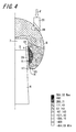
- FIG. 4 is a stress distribution diagram showing an analysis result of Example 1 simulating the artificial hip joint 1A illustrated in FIG. 1 .
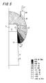
- FIG. 5 is a stress distribution diagram showing an analysis result of Comparison Example 1.
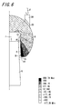
- FIG. 6 is a stress distribution diagram showing an analysis result of Comparison Example 2. In each diagram, the same reference numerals are assigned to portions corresponding to those of the artificial hip joint 1A in FIG. 1 .
- the inventors have carried out a stress analysis by using a finite element method (abbreviated to FEM) in order to identify the stress generated when an external force is applied to the head 8.
- FEM finite element method
- the stress analysis model illustrated in FIG. 3 is used.
- the analysis model simulating the artificial hip joint 1A in FIG. 1 is "Example 1”
- the analysis model simulating the artificial hip joint without the sleeve is "Comparison Example 1”
- the analysis model simulating the artificial hip joint having the simple conical sleeve having the regular thickness which is similar to the conventional technology is "Comparison Example 2".
- the material of a member corresponding to the head 8 is alumina
- the material of a member corresponding to the neck portion 5 of the stem is a cobalt-chromium-molybdenum (CCM) alloy
- the material of a member corresponding to the sleeves 2 and 2A is Ti-6Al-4V.
- the design of the head 8 is unified.
- the design of the neck portion 5 is the same in Example 1 and Comparison Example 2. However, in the design of the neck portion 5 in Comparison Example 1, only a portion corresponding to the thickness of the sleeve is caused to be thicker than that of the neck portion 5 in Example 1 and Comparison Example 2.
- alumina corresponds to the head
- CCM corresponds to the neck portion
- Ti-6Al-4V corresponds to the sleeve
- Fe corresponds to the pressing jig
- Cu corresponds to the copper ring.
- Material Friction Coefficient Young's Modulus [GPa] Alumina 0.3 400 CCM 0.3 213 Ti-6Al-4V 0.3 110 Fe 0.3 200 Cu 0.3 120
- Example 1 (Embodiment 1), Comparison Example 1 (no sleeve), and Comparison Example 2 (with the conical sleeve), stress distribution generated when the load F of 46 kN is applied to the head 8 by using the pressing jig 30 is illustrated in each of FIGS. 4 , 5 and 6 .
- a position generating the maximum principal stress is indicated by R.
- a maximum principal stress value (unit: MPa) obtained through the analysis is shown in Table 2.
- Table 2 Shape Maximum Principal Stress [MPa]
- Example 1 Embodiment 1 ( FIG. 4 ) 564.3 Comparison Example 1 No sleeve ( FIG. 5 ) 674.4 Comparison Example 2 Simple conical ( FIG. 6 ) 656.8
- Example 1 the contact point of the sleeve 2A and the head 8 is set to a place having a large cross-sectional area, avoiding the thin opening portion 14 and the vicinity thereof, and thus, as illustrated in FIG. 4 , the position R generating the maximum principal stress moves deep inside the concavity 7 in the insertion direction A.
- the maximum principal stress value decreases in Example 1. In accordance with this, it is considered that fracture strength increases.
- Comparison Example 2 illustrated in FIG. 6 , stress is concentrated in the vicinity of the thinnest opening portion 14 in the head 8.
- the value of the maximum principal stress is also much greater than that in Example 1.
- interfaces increase by causing the sleeve 2 to be inserted between the head 8 and the neck portion 5, thereby achieving a decrease of stress due to the sliding.
- the maximum principal stress value slightly decreases.
- fracture strength slightly increases.
- FIG. 7 is a cross-sectional view illustrating an artificial hip joint 1B according to Embodiment 2 of the invention.
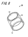
- FIG. 8 is a perspective view of a sleeve 2B which is used in the artificial hip joint 1B.
- the same reference numerals are assigned to portions corresponding to those in Embodiment 1 described above.
- the artificial hip joint 1B of the present embodiment in common with Embodiment 1, includes the stem 6, the head 8, and the sleeve 2B.
- the stem 6 has the neck portion 5 which has the truncated conical outer circumferential surface 4 decreased in diameter toward the tip thereof.
- the head 8 is provided with the concavity 7 in which the neck portion 5 is inserted, and the head 8 has the inner surface defining the concavity 7 which inner surface includes the truncated conical inner circumferential surface 10 decreased in diameter toward the insertion direction of inserting the neck portion 5.
- the sleeve 2B is inserted between the outer circumferential surface 4 of the neck portion 5 inserted into the concavity 7, and the inner circumferential surface 10 of the head 8.
- the sleeve 2B has the inner circumferential portion 13 which makes contact with the outer circumferential surface 4 of the neck portion 5, and the outer circumferential portion 16 which makes contact with the inner circumferential surface 10 of the head 8.
- a slit 12 which has a substantially cylindrical shape in a mounted state and extends in the insertion direction A from one end portion arranged on the opening portion side 14 of the sleeve 2B is formed between the inner circumferential portion 13 and the outer circumferential portion 16.
- the slit 12 is formed in the sleeve 2B, the vicinity of the opening portion 14 of the head 8 is deformed when a load is applied to the head 8. Therefore, in accordance with this deformation, the outer circumferential portion 16 of the sleeve 2B which makes contact with the inner circumferential surface 10 of the head 8 can be warped. As a result, it is possible to prevent stress from being concentrated at a relatively thin portion, within a range of the uniform length ⁇ L2 from the end surface 15 of the head 8. Thus, it is possible to improve fracture strength of the head 8.
- a forming length L5 of the slit 12 in the sleeve 2B is set such that the outer circumferential portion 16 can be warped following deformation which occurs when the head 8 receives a load, thereby allowing the stress concentration portion to move to a place where the thickness of the head 8 is relatively great.
- the lengths of fit on the inner and outer surfaces of the sleeve 2B are set to be equivalent to each other and to have sufficient lengths. Therefore, a risk of obliquely fitting the neck portion 5 can be decreased similar to the conventional simple conical sleeve 2.
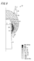
- FIG. 9 is a stress distribution diagram showing an analysis result of a model simulating the artificial hip joint 1B in the present embodiment.
- the analysis method complies with that in Analysis Example 1.
- the stress analysis model illustrated in FIG. 3 is used.
- the analysis model simulating the artificial hip joint 1B in FIG. 7 is adopted to be "Example 2", thereby analyzing stress generated when the load F of 46 kN is applied to the head 8, through the FEM analysis.
- Software used in the FEM analysis is general-purpose analysis software "ANSYS Workbench ver.13" similar to that in Analysis Example 1.
- the setting values for the FEM analysis conditions are in common with those in Analysis Example 1.
- Example 2 since the sleeve 2B has the slit 12, as illustrated in FIG. 9 , the position R generating the maximum principal stress moves from the opening portion 14 of the concavity 7 to deep inside thereof. As a result, the maximum principal stress value decreases.
- interfaces increase by causing the sleeve 2B to be inserted, sliding is generated among the head 8, the sleeve 2B and the neck portion 5, thereby being actuated to decrease stress generated in the head 8, by the sliding. Therefore, it is considered that an effect of decreasing stress generated in the head 8 is exhibited in cooperation with this action.
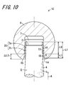
- FIG. 10 is a cross-sectional view illustrating an artificial hip joint 1C according to Embodiment 3 of the invention.
- FIG. 11 is a perspective view of a sleeve 2C which is used in the artificial hip joint 1C.
- FIG. 12 is an exploded perspective view of the sleeve 2C which is used in the artificial hip joint 1C.
- the same reference numerals are assigned to portions corresponding to those in Embodiment 1.
- the artificial hip joint 1C of the present embodiment includes the stem 6, the head 8, and the sleeve 2C.
- the stem 6 has the neck portion 5 which has the truncated conical outer circumferential surface 4 decreased in diameter toward a tip thereof.
- the head 8 is provided with the concavity 7 in which the neck portion 5 is inserted, and the head 8 has the inner surface defining the concavity 7 which inner surface includes the truncated conical inner circumferential surface 10 decreased in diameter toward the insertion direction of inserting the neck portion 5.
- the sleeve 2C is inserted between the outer circumferential surface 4 of the neck portion 5 inserted into the concavity 7, and the inner circumferential surface 10 of the head 8.
- the sleeve 2C has a multi-layer structure in which a plurality of sleeve sections having substantially the same shape are stacked. In the present embodiment, the sleeve 2C has a two-layer structure.
- the sleeve 2C of the present embodiment has a hollow truncated conical outer cylinder section 2a and a hollow truncated conical inner cylinder section 2b which is fit inside the outer cylinder section 2a and of which the length in an axial direction is formed to be longer than the outer cylinder section 2a.
- the outer circumferential surface of the outer cylinder section 2a constitutes the outer circumferential portion 16 which makes contact with the inner circumferential surface 10 of the head 8
- the inner circumferential surface of the inner cylinder section 2b constitutes the inner circumferential portion 13 which makes contact with the outer circumferential surface 4 of the neck portion 5.
- end surfaces on small diameter sides thereof are set to be flush with each other.
- a space S is formed between a protrusion section 18 and the inner circumferential surface 10 of the head 8.
- the space S is formed in the vicinity of the opening portion 14 of the sleeve 2C so as to provide a region which does not make contact with the inner circumferential surface 10 of the head 8.
- the sleeve 2C of the present embodiment has a structure in which the outer cylinder section 2a and the inner cylinder section 2b having substantially the same shape are stacked in a double layer. Therefore, compared to a case where the sleeve is in a single body, sliding surfaces between the outer cylinder section 2a and the inner cylinder section 2b increase, and thus, it is possible to decrease stress generated in the head 8.
- the sleeve 2C of the present embodiment is composed of the combination of the simple conical outer cylinder section 2a and inner cylinder section 2b, thereby being easily processed and being excellent in productivity. Furthermore, due to the multi-layer structure, the thickness adjustment is easy.
- the outer cylinder section 2a and the inner cylinder section 2b are not necessarily tapered in the same manner.
- the sleeve 2C can have a multi-layer structure including equal to or more than three layers.
- FIG. 13 is a stress distribution diagram showing an analysis result of a model simulating the artificial hip joint 1C in the present embodiment.
- the analysis method complies with that in Analysis Example 1.
- the stress analysis model illustrated in FIG. 3 is used.
- the analysis model simulating the artificial hip joint 1C in FIG. 10 is adopted to be "Example 3", thereby analyzing stress generated when the load F of 46 kN is applied to the head 8, through the FEM analysis.
- Software used in the FEM analysis is general-purpose analysis software "ANSYS Workbench ver.13" similar to that in Analysis Example 1.
- the setting values for the FEM analysis conditions are in common with those in Analysis Example 1.
- Example 3 a position where the outer cylinder section 2a of the sleeve 2C makes contact with the inner circumferential surface 10 of the head 8 is separated from the opening portion 14. Therefore, as illustrated in FIG. 13 , the position R generating the maximum principal stress moves from the opening portion 14 of the concavity 7 to deep inside thereof. As a result, the maximum principal stress value decreases.
- the stress concentration portion moves to a region having great strength, it is possible to decrease the maximum principal stress value generated in the head 8 and to improve fracture strength of the head 8.
- the interfaces increase and sliding is generated between the outer cylinder section 2a and the inner cylinder section 2b, and thus, this also allows an effect of decreasing stress generated in the head 8 to be achieved.
- FIG. 14 is a cross-sectional view illustrating an artificial hip joint 1D according to Embodiment 4 of the invention.
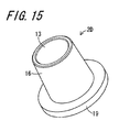
- FIG. 15 is a perspective view of a sleeve 2D which is used in the artificial hip joint 1D.
- the same reference numerals are assigned to portions corresponding to those in the above-described embodiments.
- the artificial hip joint 1D of the present embodiment in common with Embodiment 1, includes the stem 6, the head 8, and the sleeve 2D.
- the stem 6 has the neck portion 5 which has the truncated conical outer circumferential surface 4 decreased in diameter toward the tip thereof.
- the head 8 is provided with the concavity 7 in which the neck portion 5 is inserted, and the head 8 has the inner surface defining the concavity 7 which inner surface includes the truncated conical inner circumferential surface 10 decreased in diameter toward the insertion direction of inserting the neck portion 5.
- the sleeve 2D is inserted between the outer circumferential surface 4 of the neck portion 5 inserted into the concavity 7, and the inner circumferential surface 10 of the head 8.
- the sleeve 2D of the present embodiment has the inner circumferential portion 13 which makes contact with the outer circumferential surface 4 of the neck portion 5, the outer circumferential portion 16 which makes contact with the inner circumferential surface 10 of the concavity 7, and a flange portion 19 which is widened toward the opening portion 14 side. Then, the flange portion 19 formed at the end portion on the opening portion 14 side is configured to be in surface contact with the end surface 15 which is a peripheral surface of the opening portion 14 of the head 8. In the present embodiment, the end surface 15 of the head 8 is set at a place having a relatively great thickness.
- the sleeve 2D of the present embodiment differently from Embodiments 1 to 3, there is no need to ensure a region for forming the space S or the slit 12 in the vicinity of the opening portion 14 of the head 8.
- the outer circumferential portion 16 of the sleeve 2D makes contact with the inner circumferential surface 10 of the head 8 from the position of the opening portion 14, even though the overall height H of the head 8 is decreased, it is possible to ensure the sufficient length of fit. Accordingly, since the head 8 can be decreased in size to the extent that the minimal necessary caput sliding area can be obtained, it is possible to provide a small head 8.
- the sliding area also decreases, and thus, it is easy to perform polishing of the surface of the head 8.
- the space S or the slit 12 may be formed in the vicinity of the opening portion 14 of the head 8.
- the length of the inner circumferential portion 13 when seen in the insertion direction A is a length including the flange portion 19
- a length of fit L8 with the neck portion 5 can be elongated with respect to the overall height H of the head 8. Accordingly, when the neck portion 5 is fit inside the sleeve 2D so as to fix the head 8 to the stem 6, it is possible to lower the possibility that the neck portion 5 fits obliquely, and to prevent fracture strength of the head 8 from being degraded.
- the load when a load acts on the head 8, the load also acts on the sleeve 2D through the head 8. Since the sleeve 2D receives the load at the outer circumferential portion 16 and the flange portion 19, stress generated in the head 8 is dispersed in a direction from the opening portion 14 along the outer circumferential portion 16 and a direction along the flange portion 19. As a result, the value of the maximum principal stress decreases. Moreover, in the present embodiment, since the end surface 15 which makes contact with the flange portion 19 is set to a place having a great thickness, it is possible to improve fracture strength.
- FIG. 16 is a stress distribution diagram showing an analysis result of a model simulating the artificial hip joint 1D in the present embodiment.
- the analysis method complies with that in Analysis Example 1.
- the stress analysis model illustrated in FIG. 3 is used.
- the analysis model simulating the artificial hip joint 1D in FIG. 14 is adopted to be "Example 4", thereby analyzing stress generated when the load F of 46 kN is applied to the head 8, through the FEM analysis.
- Software used in the FEM analysis is general-purpose analysis software "ANSYS Workbench ver.13" similar to that in Analysis Example 1.
- the setting values for the FEM analysis conditions are in common with those in Analysis Example 1.
- Example 4 As seen from the analysis result, it has been confirmed that the maximum principal stress value generated in the head 8 decreases by using the sleeve 2D of Embodiment 4.
- Example 4 As illustrated in FIG. 16 , even though the position R generating the maximum principal stress is in the vicinity of the opening portion 14, the maximum principal stress value is sufficiently small compared to Comparison Examples 1 and 2. It is considered that since the flange portion 19 which makes contact with the end surface 15 of the head 8 is formed in the sleeve 2D, when the load F is applied to the head 8, stress generated in the vicinity of the opening portion 14 of the head 8 is dispersed not only in the direction of the outer circumferential portion 16 but also in the direction of the flange portion 19.
- an excellent effect is exhibited as follows.
- Each of the artificial hip joints 1A to 1D according to the invention is configured to include the head 8 made of ceramics, and the stem 6 and the sleeves 2A to 2D which are made of metal. Therefore, combinations of various types of the heads 8 and various types of the stems 6 are possible according to selection of the sleeves 2A to 2D, and thus, it is possible to provide various types of artificial hip joints having various sizes and materials.
- the length of taper-fit in which the outer circumferential portions 16 of the sleeves 2A to 2D make contact with the inner circumferential surface 10 of the head 8 and the length of taper-fit in which the inner circumferential portion 13 makes contact with the outer circumferential surface 4 of the neck portion 5 of the stem 6 can respectively ensure the sufficient lengths, it is possible to lower the possibility that the neck portion 5 fits obliquely.
- it is possible to move the stress concentration portion of the head 8 to the position which is advantageous for strength or to disperse stress it is possible to decrease the maximum principal stress value of the head 8, and to improve fracture strength of the head 8.
- each taper angle between the outer circumferential portions 16 of the sleeves 2A to 2D and the inner circumferential surface 10 of the head 8 is caused to be the same so as to make surface contact therewith.
- the taper angles of the outer circumferential portions 16 of the sleeves 2A to 2D are caused to be smaller than the taper angle of the inner circumferential surface 10 of the head 8, and thus, the sleeves 2A to 2D mounted on the neck portion 5 may be brought into contact with the inner circumferential surface 10 of the concavity 7 at the position deeper than the concavity 7 of the head 8 in the insertion direction of inserting the neck portion 5, that is, a so-called "deep" fitting structure.
- the taper angles of the inner circumferential portions 13 of the sleeves 2A to 2D are increased to be greater than the taper angle of the outer circumferential surface 4 of the neck portion 5, and thus, the tip 3 of the neck portion 5 may be brought into contact with the inner circumferential portion 13 at the position inside the sleeves 2A to 2D, that is, the so-called "deep" fitting structure.
Landscapes
- Health & Medical Sciences (AREA)
- Orthopedic Medicine & Surgery (AREA)
- Cardiology (AREA)
- Oral & Maxillofacial Surgery (AREA)
- Transplantation (AREA)
- Engineering & Computer Science (AREA)
- Biomedical Technology (AREA)
- Heart & Thoracic Surgery (AREA)
- Vascular Medicine (AREA)
- Life Sciences & Earth Sciences (AREA)
- Animal Behavior & Ethology (AREA)
- General Health & Medical Sciences (AREA)
- Public Health (AREA)
- Veterinary Medicine (AREA)
- Prostheses (AREA)
Abstract
Description
- The present invention relates to an artificial hip joint in which a neck portion of a stem fits a tapered concavity of a head so as to join the head and the stem together.
- Conventionally, an artificial hip joint is made of metal such as stainless steel, a cobalt-chromium alloy, or a titanium alloy, and has a stem inserted into and fixed to a thighbone, and a ceramic head, wherein the head and the stem are fixed in an integral manner or by performing taper-fitting, and a polyethylene cup is fixed onto an acetabular cartridge side in which the head is received.
- The heads mostly have a taper-fitting structure so as to be fixed to a neck portion formed at a tip portion of a metal stem. The head is configured to be adjustable in length of fit (also referred to as "a neck offset") when being attached to the stem, by changing the depth or the inner diameter of a concavity which is also called a tapered hole.
- In consideration of combination with a polyethylene cup provided on the acetabular cartridge side, a head made of ceramics such as alumina or zirconia which is a low frictional and low wear-out material is clinically used. However, the ceramic head has a problem in that damage is likely to occur due to incompatibility between the neck portion at the tip portion of the metallic stem to be joined and the concavity formed in the head.
- Incidentally, it is said that a load equal to or greater than five times one's weight at most is applied to a femur head. For example, in a case of a person weighing 80 kg, a maximum load of approximately 400 kg is repeatedly applied thereto. In this manner, since a great force is constantly applied to a hip joint of a human body for a long period of time, great strength is required for the artificial hip joint.
- In addition, a high safety factor is required for the artificial hip joint from the viewpoint of durability on a long-term basis. However, in practice, when the neck portion of the stem is inserted into the concavity formed in the ceramic head, stress distribution in a concavity section of the head becomes irregular due to even incompatibility caused by a slight scratch in the neck portion, leading to a problem of inducing a rupture in the head caused by local stress concentration.
- In order to solve such problems, in the artificial hip joint in which the neck portion of the stem is inserted into and fixed to the concavity formed in the ceramic head, there is utilized a technology of causing a conical sleeve to be inserted between an inner circumferential surface of the concavity and an outer circumferential surface of the neck portion of the stem.
- In such a conventional technology, the length of fit, that is, the neck offset of the neck portion with respect to the head is easily changed by adjusting the thickness of the sleeve, and thus, without preparing various types of the ceramic heads, it is possible to cope with a plurality of different lengths of fit even with one type of the head (for example, refer to Patent Literature 1,
Patent Literature 2, and Non-Patent Literature 1). -
- Patent Literature 1: Japanese Unexamined Patent Publication
JP-A 3-47253 (1991 - Patent Literature 2: Japanese Unexamined Patent Publication
JP-A 2002-330983 - Non-Patent Literature 1: "NEWS RELEASE, Information about New Technology and New Products: New Generation Ceramic Head and Liner Containing Vitamin E for Artificial Hip Joint Tied Up with Latest Technology Introduced in Japan" [online], May 15, 2012, Biomet Japan Inc., [searched on October 29, 2012], Internet (URL: https://www.biomet.co.jp/information/img/Biomet_Release051 5.pdf)
- In the above-described conventional technology, fracture strength of a ceramic head is enhanced by varying the thickness of a sleeve and causing a neck portion to fit a concavity at a position deeper than an opening portion of the concavity in an insertion direction of the neck portion. However, as the length of fit of the neck portion and the sleeve becomes short, there is a high possibility that the neck portion fits obliquely. In contrast, if the overall height of the head is increased in order to ensure the length of fit, it is difficult to ensure a sufficient thickness at a stress concentration portion generated in the vicinity of the opening portion of the concavity, thereby leading to a problem in that necessary strength cannot be achieved.
- An object of the invention is to provide an artificial hip joint in which the length of fit can be ensured without increasing the overall height of the head, and stress generated in the head can be reduced by mitigating concentration of stress.
- The invention provides an artificial hip joint including:
- a stem having a neck portion which has a truncated conical outer circumferential surface decreased in diameter toward a tip thereof,
- a head provided with a concavity in which the neck portion is inserted, an inner surface of the concavity of the head including a truncated conical inner circumferential surface decreased in diameter toward an insertion direction of inserting the neck portion, and
- a sleeve being inserted between an outer circumferential surface of the neck portion inserted into the concavity and an inner circumferential surface of the head,
- the sleeve having an inner circumferential portion which makes contact with the outer circumferential surface of the neck portion, and an outer circumferential portion which makes contact with the inner circumferential surface of the head in a region farther away than an opening portion of the concavity in the insertion direction.
- Furthermore, the invention provides an artificial hip joint including:
- a stem having a neck portion which has a truncated conical outer circumferential surface decreased in diameter toward a tip thereof,
- a head provided with a concavity in which the neck portion is inserted, an inner surface of the concavity of the head including a truncated conical inner circumferential surface decreased in diameter toward an insertion direction of inserting the neck portion, and
- a sleeve inserted between an outer circumferential surface of the neck portion inserted into the concavity and an inner circumferential surface of the head,
- the sleeve having an inner circumferential portion which makes contact with the outer circumferential surface of the neck portion, and an outer circumferential portion which makes contact with the inner circumferential surface of the head, the sleeve being provided with a slit which is formed between the inner circumferential portion and the outer circumferential portion so as to extend in the insertion direction from one end portion of the sleeve located on an opening portion side of the concavity.
- Furthermore, the invention provides an artificial hip joint including:
- a stem having a neck portion which has a truncated conical outer circumferential surface decreased in diameter toward a tip thereof,
- a head provided with a concavity in which the neck portion is inserted, an inner surface of the concavity of the head including a truncated conical inner circumferential surface decreased in diameter toward an insertion direction of inserting the neck portion, and
- a sleeve inserted between an outer circumferential surface of the neck portion inserted into the concavity and an inner circumferential surface of the head,
- the sleeve having a multi-layer structure in which a plurality of sleeve sections are stacked.
- Furthermore, the invention provides an artificial hip joint including:
- a stem having a neck portion which has a truncated conical outer circumferential surface decreased in diameter toward a tip thereof,
- a head provided with a concavity in which the neck portion is inserted, an inner surface of the concavity of the head including a truncated conical inner circumferential surface decreased in diameter toward an insertion direction of inserting the neck portion, and
- a sleeve inserted between an outer circumferential surface of the neck portion inserted into the concavity and an inner circumferential surface of the head,
- the sleeve having an inner circumferential portion which makes contact with the outer circumferential surface of the neck portion, an outer circumferential portion which makes contact with the inner circumferential surface of the concavity, and a flange portion which makes contact with a peripheral surface of an opening portion of the concavity.
- In the invention, it is preferable that the sleeve is made of Ti or a Ti alloy.
- According to the invention, an inner circumferential portion of a sleeve makes contact with an outer circumferential surface of a neck portion, and an outer circumferential portion of the sleeve makes contact with an inner circumferential surface of a head at a region farther away than an opening portion of a concavity in an insertion direction. Thus, a stress concentration portion generated in the head can be moved to a site having the cross-sectional area larger than the opening portion of the head. Accordingly, it is possible to provide an artificial hip joint in which stress generated in the head can be reduced by mitigating concentration of stress. Since the length of fit of the outer circumferential surface of the neck portion and the inner circumferential portion of the sleeve which is in contact therewith can achieve a sufficient length, it is possible to ensure fixing strength of the head with respect to the neck portion. Accordingly, it is possible to realize miniaturization of the head by lowering the overall height of the head to the extent that the minimal necessary sliding area of the head can be obtained. Since the inner circumferential portion of the sleeve becomes a guide when the head is mounted on the neck portion, it is possible to lower the possibility that the head and the neck portion fit obliquely.
- In addition, according to the invention, the inner circumferential portion of the sleeve makes contact with the outer circumferential surface of the neck portion, the outer circumferential portion of the sleeve makes contact with the inner circumferential surface of the head, and a slit extending in the insertion direction from one end portion of the sleeve is formed between the inner circumferential portion and the outer circumferential portion thereof. Accordingly, it is possible to mitigate concentration of stress by moving the stress concentration portion generated in the head to the site having the cross-sectional area larger than the opening portion of the head.
- Furthermore, according to the invention, the sleeve is realized by a multi-layer structure in which a plurality of sleeve sections are stacked. Accordingly, sliding is generated at interfaces of the plurality of sleeve sections, and thus, it is possible to mitigate stress generated in the head.
- Furthermore, according to the invention, the inner circumferential portion of the sleeve makes contact with the outer circumferential surface of the neck portion, the outer circumferential portion of the sleeve makes contact with the inner circumferential surface of the concavity, and a flange portion makes contact with a peripheral surface of the opening portion of the concavity. Accordingly, it is possible to mitigate stress by causing the concentration of stress generated in the vicinity of the opening portion of the head to disperse in a direction along the outer circumferential portion of the sleeve and a direction along the flange portion.
- Furthermore, according to the invention, the sleeve is made of Ti or a Ti alloy suitable for corrosion resistance and malleability. Thus, it is possible to improve strength of a caput of the artificial hip joint, and simultaneously, it is possible to improve a fitting force of the caput and the neck.
- The objects, characteristics, and advantages of the invention will become clearer through the following descriptions and drawings in detail.
-
FIG. 1 is a cross-sectional view illustrating anartificial hip joint 1A according to Embodiment 1 of the invention; -
FIG. 2 is a perspective view of asleeve 2A which is used in the artificial hip joint 1A illustrated inFIG. 1 ; -
FIG. 3 is a diagram illustrating a stress analysis model of an artificial hip joint; -
FIG. 4 is a stress distribution diagram showing an analysis result of Example 1 simulating the artificial hip joint 1A illustrated inFIG. 1 ; -
FIG. 5 is a stress distribution diagram showing an analysis result of Comparison Example 1; -
FIG. 6 is a stress distribution diagram showing an analysis result of Comparison Example 2; -
FIG. 7 is a cross-sectional view illustrating an artificial hip joint 1B according toEmbodiment 2 of the invention; -
FIG. 8 is a perspective view of asleeve 2B which is used in the artificial hip joint 1B illustrated inFIG. 7 ; -
FIG. 9 is a stress distribution diagram showing an analysis result of Example 2 simulating the artificial hip joint 1B illustrated inFIG. 7 ; -
FIG. 10 is a cross-sectional view illustrating an artificial hip joint 1C according toEmbodiment 3 of the invention; -
FIG. 11 is a perspective view of a sleeve 2C which is used in the artificial hip joint 1C illustrated inFIG. 10 ; -
FIG. 12 is an exploded perspective view of the sleeve 2C which is used in the artificial hip joint 1C illustrated inFIG. 10 ; -
FIG. 13 is a stress distribution diagram showing a stress analysis result of Example 3 simulating the artificial hip joint 1C illustrated inFIG. 10 ; -
FIG. 14 is a cross-sectional view illustrating an artificial hip joint 1D according toEmbodiment 4 of the invention; -
FIG. 15 is a perspective view of asleeve 2D which is used in the artificial hip joint 1D illustrated inFIG. 14 ; and -
FIG. 16 is a stress distribution diagram showing a stress analysis result of Example 4 simulating the artificial hip joint 1D illustrated inFIG. 14 . - Hereinafter, suitable embodiments of the invention will be described in detail with reference to the drawings.
-
FIG. 1 is a cross-sectional view illustrating an artificial hip joint 1A according to Embodiment 1 of the invention, andFIG. 2 is a perspective view of asleeve 2A which is used in the artificial hip joint 1A illustrated inFIG. 1 . The artificial hip joint 1A of the present embodiment includes astem 6, ahead 8, and thesleeve 2A. Thestem 6 has aneck portion 5 which has a truncated conical outercircumferential surface 4 decreased in diameter toward atip 3 thereof. Thehead 8 is provided with aconcavity 7 in which theneck portion 5 is inserted, and thehead 8 has an inner surface 9 defining theconcavity 7 which inner surface includes a truncated conical innercircumferential surface 10 decreased in diameter toward an insertion direction A of inserting theneck portion 5. Thesleeve 2A is inserted between the outercircumferential surface 4 of theneck portion 5 inserted into theconcavity 7, and the innercircumferential surface 10 of thehead 8. - The
stem 6 is made of metal such as stainless steel, a cobalt-chromium alloy, or a titanium alloy. An end portion of thestem 6 which is opposite to a side inserted into a thighbone is provided with theneck portion 5 on which thehead 8 is mounted. As thehead 8, a head made of ceramics such as alumina or zirconia which is a low frictional and low wear material is employed. - The
sleeve 2A is made of titanium (Ti) or a titanium alloy, and thesleeve 2A is an annular member having a substantially truncated conical outer shape. When using thesleeve 2A, thesleeve 2A may be mounted inside theconcavity 7 of thehead 8 in advance. There are multiple types of standards for a taper shape of theneck portion 5. The shape of thesleeve 2A is adjusted so as to be able to be combined with the taper shape corresponding to the standard of theneck portion 5 to be mounted, with respect to onehead 8. Even though the illustratedsleeve 2A has a cylindrical form in which an end portion on a small diameter side is open, thesleeve 2A may have a cup-shaped form in which the end portion on the small diameter side is closed. - The
sleeve 2A of the present embodiment has an innercircumferential portion 13 which makes contact with the outercircumferential surface 4 of theneck portion 5, and an outercircumferential portion 16 which makes contact with the innercircumferential surface 10 of thehead 8. A second length L2 of the outercircumferential portion 16 is formed to be shorter compared to the overall length (equivalent to the overall length of the sleeve) L1 of the innercircumferential portion 13 when seen in the insertion direction A. In other words, an edge of the outercircumferential portion 16 on the large diameter side is set to be at a position farther away than anend surface 15 of anopening portion 14 in the insertion direction A by the distance ΔL1. Therefore, a thin innercircumferential section 17 having a third length L3 (= L1 - L2) is formed in the innercircumferential portion 13 based on a difference in length with respect to the outercircumferential portion 16. In this manner, when thesleeve 2A is seen in the insertion direction A, a contact position of the innercircumferential portion 13 with respect to the outercircumferential surface 4 of theneck portion 5 is different from a contact position of the outercircumferential portion 16 with respect to the innercircumferential surface 10 of thehead 8. - It is desirable that the
sleeve 2A does not protrude from theconcavity 7 of thehead 8. In a case of causing thesleeve 2A to protrude, it is desirable to set thesleeve 2A so as not to stick out of a virtual spherical surface including an outer surface of thehead 8. - The inner
circumferential portion 13 has the innercircumferential section 17 which is longer than the outercircumferential portion 16 by the third length L3, and thus, it is possible to effectively make contact with the outercircumferential surface 4 of theneck portion 5 and to ensure a length of fit L4 which is necessary with respect to theneck portion 5. In accordance with a thickness T of thesleeve 2A, it is possible to adjust the length of fit L4 and a neck offset (a distance from the center of thehead 8 to a tip of the neck portion 5) with respect to theneck portion 5 of thehead 8. In other words, if the thickness T of thesleeve 2A is increased, the inner diameter contracts, and thus, the length of fit L4 is shortened and the neck offset increases. In contrast, if the thickness T of thesleeve 2A is decreased, the inner diameter expands, and thus, the length of fit L4 is lengthened and the neck offset decreases. Even though there is no particular limitation for the thickness of thesleeve 2A, it is desirable to be practically in a range of 0.5 to 5.0 mm. - In this manner, since the length of fit L4 of the inner
circumferential portion 13 and the outercircumferential surface 4 can be changed and a position of thehead 8 with respect to theneck portion 5 can be adjusted by changing the thickness T of thesleeve 2A, it is possible to set different offsets in thesame head 8 andstem 6 by preparing thesleeves 2A respectively having different thicknesses T. - Regarding a difference of the standards related to the taper shape of the
neck portion 5, it is possible to use the same or a small number of types of thehead 8 and thestem 6 by causing thesleeve 2A to be inserted. In other words, even though thestem 6 has a different standard, by causing the shape of thesleeve 2A disposed between thehead 8 and theneck portion 5 to correspond thereto, it is possible to cause thehead 8 and theneck portion 5 to be compatible with each other and to adjust the length of fit L4. In this manner, in accordance with thesleeve 2A to be inserted therebetween, it is possible to achieve a stable fitting state of thehead 8 and theneck portion 5. - The outer
circumferential portion 16 makes contact with the innercircumferential surface 10 of thehead 8 from a position retracted further than theend surface 15 of the openingportion 14 by the length ΔL1, that is, from an intermediate portion of theconcavity 7 in the insertion direction A, throughout the second length L2 in the insertion direction A. As the contact region of the outercircumferential portion 16 is retracted from theend surface 15, a region in which thehead 8 makes contact with the outercircumferential portion 16 of thesleeve 2A is changed to a region having a relatively large cross-sectional area, avoiding a region of which the thickness is relatively thin in the range of the length ΔL1 from theend surface 15. Accordingly, it is possible to move a stress concentration portion of thehead 8 to a position having the large cross-sectional area which is advantageous for strength, and to reduce the generated maximum principal stress. - The artificial hip joint 1A according to the present embodiment exhibits the effects described below. Since the region at which the inner
circumferential surface 10 of thehead 8 and the outercircumferential portion 16 of thesleeve 2A make contact with each other is changed to a region having a great thickness B and high strength, the place of stress concentration moves to this region, and thus, it is possible to prevent strength degradation and a fracture of thehead 8 from occurring. Since the length of fit L4 of the outercircumferential surface 4 of theneck portion 5 of thestem 6 and the innercircumferential portion 13 of thesleeve 2A which is in contact therewith is caused to have a sufficient length, it is possible to ensure fitting strength with respect to theneck portion 5 of thehead 8. Accordingly, it is possible to realize miniaturization of thehead 8 by lowering an overall height H of thehead 8 to the extent that the minimal necessary sliding area of the head can be obtained, and to exhibit excellent fixing strength by ensuring the sufficiently great length of fit L4 with respect to the overall height H of thehead 8. The innercircumferential section 17 which is longer than the outercircumferential portion 16 by the third length L3 is provided in the innercircumferential portion 13 of thesleeve 2A, and thus, the innercircumferential section 17 becomes a guide when thehead 8 is mounted on theneck portion 5. Therefore, it is possible to sufficiently lower the possibility of being fit obliquely with respect to theneck portion 5. -
FIG. 3 is a diagram illustrating a stress analysis model of an artificial hip joint.FIG. 4 is a stress distribution diagram showing an analysis result of Example 1 simulating the artificial hip joint 1A illustrated inFIG. 1 .FIG. 5 is a stress distribution diagram showing an analysis result of Comparison Example 1.FIG. 6 is a stress distribution diagram showing an analysis result of Comparison Example 2. In each diagram, the same reference numerals are assigned to portions corresponding to those of the artificial hip joint 1A inFIG. 1 . - In the artificial hip joint 1A according to Embodiment 1, the inventors have carried out a stress analysis by using a finite element method (abbreviated to FEM) in order to identify the stress generated when an external force is applied to the
head 8. As an analysis method, the stress analysis model illustrated inFIG. 3 is used. As an analysis target, the analysis model simulating the artificial hip joint 1A inFIG. 1 is "Example 1", the analysis model simulating the artificial hip joint without the sleeve is "Comparison Example 1", and the analysis model simulating the artificial hip joint having the simple conical sleeve having the regular thickness which is similar to the conventional technology is "Comparison Example 2". - In the stress analysis model of
FIG. 3 , the material of a member corresponding to thehead 8 is alumina, the material of a member corresponding to theneck portion 5 of the stem is a cobalt-chromium-molybdenum (CCM) alloy, and the material of a member corresponding to thesleeves head 8 is unified. The design of theneck portion 5 is the same in Example 1 and Comparison Example 2. However, in the design of theneck portion 5 in Comparison Example 1, only a portion corresponding to the thickness of the sleeve is caused to be thicker than that of theneck portion 5 in Example 1 and Comparison Example 2. - Then, there were calculated stress distribution generated in the
head 8 when a load F of 46 kN is applied to thehead 8 by using aniron pressing jig 30 having acopper ring 20 mounted on a tip thereof, and a maximum principal stress value. The load 46 kN used in the analysis is the criteria of average strength of thehead 8 in accordance with the guidance of the Food and Drug Administration (abbreviated to FDA). Software used in the FEM analysis is general-purpose analysis software "ANSYS Workbench ver.13". Setting values for FEM analysis conditions are shown in Table 1. In Table 1, respectively, alumina corresponds to the head, CCM corresponds to the neck portion, Ti-6Al-4V corresponds to the sleeve, Fe corresponds to the pressing jig, and Cu corresponds to the copper ring.[Table 1] Material Friction Coefficient Young's Modulus [GPa] Alumina 0.3 400 CCM 0.3 213 Ti-6Al-4V 0.3 110 Fe 0.3 200 Cu 0.3 120 - In Example 1 (Embodiment 1), Comparison Example 1 (no sleeve), and Comparison Example 2 (with the conical sleeve), stress distribution generated when the load F of 46 kN is applied to the
head 8 by using thepressing jig 30 is illustrated in each ofFIGS. 4 ,5 and6 . In each diagram, a position generating the maximum principal stress is indicated by R. A maximum principal stress value (unit: MPa) obtained through the analysis is shown in Table 2.[Table 2] Shape Maximum Principal Stress [MPa] Example 1 Embodiment 1 ( FIG. 4 )564.3 Comparison Example 1 No sleeve ( FIG. 5 )674.4 Comparison Example 2 Simple conical ( FIG. 6 )656.8 - As seen from the analysis result, it has been confirmed that the maximum principal stress value generated in the
head 8 is the lowest in Example 1 using thesleeve 2A according to Embodiment 1. In Example 1, the contact point of thesleeve 2A and thehead 8 is set to a place having a large cross-sectional area, avoiding thethin opening portion 14 and the vicinity thereof, and thus, as illustrated inFIG. 4 , the position R generating the maximum principal stress moves deep inside theconcavity 7 in the insertion direction A. As a result, compared to Comparison Example 1 and Comparison Example 2, it is considered that the maximum principal stress value decreases in Example 1. In accordance with this, it is considered that fracture strength increases. Moreover, since the interface increases by causing thesleeve 2A to be inserted compared to a case of not having thesleeve 2A, sliding is generated between thehead 8 and theneck portion 5, thereby being actuated to decrease stress generated in thehead 8, by the sliding. Therefore, it is considered that an effect of decreasing stress generated in thehead 8 is exhibited in cooperation with this action. - In Comparison Example 1 illustrated in
FIG. 5 , thehead 8 and theneck portion 5 make direct contact with each other. Therefore, as illustrated inFIG. 5 , stress is concentrated in the vicinity of the openingportion 14 which is the thinnest portion in thehead 8. In addition, the value of the maximum principal stress is also much greater than that in Example 1. Furthermore, since stress is concentrated at the thin region in the vicinity of the openingportion 14, the maximum principal stress value increases. As a result, it is considered that fracture strength is lowered. - In Comparison Example 2 illustrated in
FIG. 6 , stress is concentrated in the vicinity of thethinnest opening portion 14 in thehead 8. In addition, the value of the maximum principal stress is also much greater than that in Example 1. However, in Comparison Example 2, interfaces increase by causing thesleeve 2 to be inserted between thehead 8 and theneck portion 5, thereby achieving a decrease of stress due to the sliding. In accordance with such a stress decreasing action achieved by thesleeve 2, compared to Comparison Example 1 having no sleeve, it is considered that the maximum principal stress value slightly decreases. As a result, compared to Comparison Example 1, in Comparison Example 2, it is considered that fracture strength slightly increases. - According to the analysis result described above, compared to a case of using no sleeve (Comparison Example 1) or a case of using the conventional simple conical sleeve 2 (Comparison Example 2), it has been confirmed that the maximum principal stress value decreases by using the
sleeve 2A in Example 1. As a result, it is considered that fracture strength of thehead 8 is improved. -
FIG. 7 is a cross-sectional view illustrating an artificial hip joint 1B according toEmbodiment 2 of the invention.FIG. 8 is a perspective view of asleeve 2B which is used in the artificial hip joint 1B. The same reference numerals are assigned to portions corresponding to those in Embodiment 1 described above. - The artificial hip joint 1B of the present embodiment, in common with Embodiment 1, includes the
stem 6, thehead 8, and thesleeve 2B. Thestem 6 has theneck portion 5 which has the truncated conical outercircumferential surface 4 decreased in diameter toward the tip thereof. Thehead 8 is provided with theconcavity 7 in which theneck portion 5 is inserted, and thehead 8 has the inner surface defining theconcavity 7 which inner surface includes the truncated conical innercircumferential surface 10 decreased in diameter toward the insertion direction of inserting theneck portion 5. Thesleeve 2B is inserted between the outercircumferential surface 4 of theneck portion 5 inserted into theconcavity 7, and the innercircumferential surface 10 of thehead 8. - The
sleeve 2B has the innercircumferential portion 13 which makes contact with the outercircumferential surface 4 of theneck portion 5, and the outercircumferential portion 16 which makes contact with the innercircumferential surface 10 of thehead 8. A slit 12 which has a substantially cylindrical shape in a mounted state and extends in the insertion direction A from one end portion arranged on theopening portion side 14 of thesleeve 2B is formed between the innercircumferential portion 13 and the outercircumferential portion 16. - As the
slit 12 is formed in thesleeve 2B, the vicinity of the openingportion 14 of thehead 8 is deformed when a load is applied to thehead 8. Therefore, in accordance with this deformation, the outercircumferential portion 16 of thesleeve 2B which makes contact with the innercircumferential surface 10 of thehead 8 can be warped. As a result, it is possible to prevent stress from being concentrated at a relatively thin portion, within a range of the uniform length ΔL2 from theend surface 15 of thehead 8. Thus, it is possible to improve fracture strength of thehead 8. - A forming length L5 of the
slit 12 in thesleeve 2B is set such that the outercircumferential portion 16 can be warped following deformation which occurs when thehead 8 receives a load, thereby allowing the stress concentration portion to move to a place where the thickness of thehead 8 is relatively great. - In the present embodiment, similar to the conventional simple
conical sleeve 2, the lengths of fit on the inner and outer surfaces of thesleeve 2B are set to be equivalent to each other and to have sufficient lengths. Therefore, a risk of obliquely fitting theneck portion 5 can be decreased similar to the conventional simpleconical sleeve 2. - An analysis has been carried out similar to that in Embodiment 1 regarding stress generated when an external force is applied to the
head 8 of the artificial hip joint 1B inEmbodiment 2.FIG. 9 is a stress distribution diagram showing an analysis result of a model simulating the artificial hip joint 1B in the present embodiment. - The analysis method complies with that in Analysis Example 1. In other words, the stress analysis model illustrated in
FIG. 3 is used. As the analysis target, the analysis model simulating the artificial hip joint 1B inFIG. 7 is adopted to be "Example 2", thereby analyzing stress generated when the load F of 46 kN is applied to thehead 8, through the FEM analysis. Software used in the FEM analysis is general-purpose analysis software "ANSYS Workbench ver.13" similar to that in Analysis Example 1. The setting values for the FEM analysis conditions are in common with those in Analysis Example 1. - The analysis result is shown in
FIG. 9 and Table 3. "Comparison Example 1" and "Comparison Example 2" in Table 3 are in common with those in Analysis Example 1.[Table 3] Shape Maximum Principal Stress [MPa] Example 2 Embodiment 2 ( FIG. 9 )490.4 Comparison Example 1 No sleeve ( FIG. 5 )674.4 Comparison Example 2 Simple conical ( FIG. 6 )656.8 - As seen from the analysis result, it has been confirmed that the maximum principal stress value generated in the
head 8 decreases by using thesleeve 2B ofEmbodiment 2. In Example 2, since thesleeve 2B has theslit 12, as illustrated inFIG. 9 , the position R generating the maximum principal stress moves from the openingportion 14 of theconcavity 7 to deep inside thereof. As a result, the maximum principal stress value decreases. In addition, since interfaces increase by causing thesleeve 2B to be inserted, sliding is generated among thehead 8, thesleeve 2B and theneck portion 5, thereby being actuated to decrease stress generated in thehead 8, by the sliding. Therefore, it is considered that an effect of decreasing stress generated in thehead 8 is exhibited in cooperation with this action. - To summarize the above descriptions, compared to a case of using no sleeve (Comparison Example 1) or a case of using the conventional simple conical sleeve 2 (Comparison Example 2), it is possible to improve fracture strength of the
head 8 by using thesleeve 2B in the present embodiment. -
FIG. 10 is a cross-sectional view illustrating an artificial hip joint 1C according toEmbodiment 3 of the invention.FIG. 11 is a perspective view of a sleeve 2C which is used in the artificial hip joint 1C.FIG. 12 is an exploded perspective view of the sleeve 2C which is used in the artificial hip joint 1C. The same reference numerals are assigned to portions corresponding to those in Embodiment 1. - The artificial hip joint 1C of the present embodiment includes the
stem 6, thehead 8, and the sleeve 2C. Thestem 6 has theneck portion 5 which has the truncated conical outercircumferential surface 4 decreased in diameter toward a tip thereof. Thehead 8 is provided with theconcavity 7 in which theneck portion 5 is inserted, and thehead 8 has the inner surface defining theconcavity 7 which inner surface includes the truncated conical innercircumferential surface 10 decreased in diameter toward the insertion direction of inserting theneck portion 5. The sleeve 2C is inserted between the outercircumferential surface 4 of theneck portion 5 inserted into theconcavity 7, and the innercircumferential surface 10 of thehead 8. The sleeve 2C has a multi-layer structure in which a plurality of sleeve sections having substantially the same shape are stacked. In the present embodiment, the sleeve 2C has a two-layer structure. - As illustrated in
FIGS. 11 and 12 , the sleeve 2C of the present embodiment has a hollow truncated conicalouter cylinder section 2a and a hollow truncated conicalinner cylinder section 2b which is fit inside theouter cylinder section 2a and of which the length in an axial direction is formed to be longer than theouter cylinder section 2a. In the sleeve 2C, the outer circumferential surface of theouter cylinder section 2a constitutes the outercircumferential portion 16 which makes contact with the innercircumferential surface 10 of thehead 8, and the inner circumferential surface of theinner cylinder section 2b constitutes the innercircumferential portion 13 which makes contact with the outercircumferential surface 4 of theneck portion 5. In the present embodiment, when theouter cylinder section 2a is stacked on theinner cylinder section 2b, end surfaces on small diameter sides thereof are set to be flush with each other. - In the sleeve 2C, an overall length L6 of the
outer cylinder section 2a is formed to be shorter compared to the overall length (equivalent to the overall length of the sleeve) L1 of theinner cylinder section 2b when seen in the insertion direction A. Therefore, when theinner cylinder section 2b and theouter cylinder section 2a are stacked, theinner cylinder section 2b protrudes from one end of theouter cylinder section 2a by a length of a difference L7 (= L1 - L6) of the lengths therebetween. A space S is formed between aprotrusion section 18 and the innercircumferential surface 10 of thehead 8. - The space S is formed in the vicinity of the opening
portion 14 of the sleeve 2C so as to provide a region which does not make contact with the innercircumferential surface 10 of thehead 8. Thus, when a load is applied to thehead 8, it is possible to move the stress concentration portion to a region having a great thickness deep inside theconcavity 7 and being away from theend surface 15 of thehead 8 by a uniform length ΔL3. As a result, in the sleeve 2C, it is possible to prevent stress from being concentrated at a relatively thin portion in the vicinity of the openingportion 14. Therefore, it is possible to improve fracture strength of thehead 8. - Moreover, the sleeve 2C of the present embodiment has a structure in which the
outer cylinder section 2a and theinner cylinder section 2b having substantially the same shape are stacked in a double layer. Therefore, compared to a case where the sleeve is in a single body, sliding surfaces between theouter cylinder section 2a and theinner cylinder section 2b increase, and thus, it is possible to decrease stress generated in thehead 8. - The sleeve 2C of the present embodiment is composed of the combination of the simple conical
outer cylinder section 2a andinner cylinder section 2b, thereby being easily processed and being excellent in productivity. Furthermore, due to the multi-layer structure, the thickness adjustment is easy. Theouter cylinder section 2a and theinner cylinder section 2b are not necessarily tapered in the same manner. The sleeve 2C can have a multi-layer structure including equal to or more than three layers. - An analysis has been carried out similar to that in Embodiment 1 regarding stress generated when an external force is applied to the
head 8 of the artificial hip joint 1C inEmbodiment 3.FIG. 13 is a stress distribution diagram showing an analysis result of a model simulating the artificial hip joint 1C in the present embodiment. The analysis method complies with that in Analysis Example 1. In other words, the stress analysis model illustrated inFIG. 3 is used. As the analysis target, the analysis model simulating the artificial hip joint 1C inFIG. 10 is adopted to be "Example 3", thereby analyzing stress generated when the load F of 46 kN is applied to thehead 8, through the FEM analysis. Software used in the FEM analysis is general-purpose analysis software "ANSYS Workbench ver.13" similar to that in Analysis Example 1. The setting values for the FEM analysis conditions are in common with those in Analysis Example 1. - The analysis result is shown in
FIG. 13 and Table 4. "Comparison Example 1" and "Comparison Example 2" in Table 4 are in common with those in Analysis Example 1.[Table 4] Shape Maximum Principal Stress [MPa] Example 3 Embodiment 3 ( FIG. 13 )514.0 Comparison Example 1 No sleeve ( FIG. 5 )674.4 Comparison Example 2 Simple conical ( FIG. 6 )656.8 - As seen from the analysis result, it has been confirmed that the maximum principal stress value generated in the
head 8 decreases by using the sleeve 2C ofEmbodiment 3. In Example 3, a position where theouter cylinder section 2a of the sleeve 2C makes contact with the innercircumferential surface 10 of thehead 8 is separated from the openingportion 14. Therefore, as illustrated inFIG. 13 , the position R generating the maximum principal stress moves from the openingportion 14 of theconcavity 7 to deep inside thereof. As a result, the maximum principal stress value decreases. In addition, since interfaces increase by causing the sleeve 2C having the two-layer structure to be inserted, sliding is generated between thehead 8 and theneck portion 5, thereby being actuated to decrease stress generated in thehead 8, by the sliding. Therefore, it is considered that an effect of decreasing stress generated in thehead 8 is exhibited in cooperation with this action. - To summarize the above descriptions, in the artificial hip joint 1C of the present embodiment, since the stress concentration portion moves to a region having great strength, it is possible to decrease the maximum principal stress value generated in the
head 8 and to improve fracture strength of thehead 8. In addition, by using the sleeve 2C having the multi-layer structure, the interfaces increase and sliding is generated between theouter cylinder section 2a and theinner cylinder section 2b, and thus, this also allows an effect of decreasing stress generated in thehead 8 to be achieved. -
FIG. 14 is a cross-sectional view illustrating an artificial hip joint 1D according toEmbodiment 4 of the invention.FIG. 15 is a perspective view of asleeve 2D which is used in the artificial hip joint 1D. The same reference numerals are assigned to portions corresponding to those in the above-described embodiments. - The artificial hip joint 1D of the present embodiment, in common with Embodiment 1, includes the
stem 6, thehead 8, and thesleeve 2D. Thestem 6 has theneck portion 5 which has the truncated conical outercircumferential surface 4 decreased in diameter toward the tip thereof. Thehead 8 is provided with theconcavity 7 in which theneck portion 5 is inserted, and thehead 8 has the inner surface defining theconcavity 7 which inner surface includes the truncated conical innercircumferential surface 10 decreased in diameter toward the insertion direction of inserting theneck portion 5. Thesleeve 2D is inserted between the outercircumferential surface 4 of theneck portion 5 inserted into theconcavity 7, and the innercircumferential surface 10 of thehead 8. - the
sleeve 2D of the present embodiment has the innercircumferential portion 13 which makes contact with the outercircumferential surface 4 of theneck portion 5, the outercircumferential portion 16 which makes contact with the innercircumferential surface 10 of theconcavity 7, and aflange portion 19 which is widened toward the openingportion 14 side. Then, theflange portion 19 formed at the end portion on the openingportion 14 side is configured to be in surface contact with theend surface 15 which is a peripheral surface of the openingportion 14 of thehead 8. In the present embodiment, theend surface 15 of thehead 8 is set at a place having a relatively great thickness. - It is desirable to set the radius of the
flange portion 19 and a thickness U seen in the insertion direction A so as to prevent theflange portion 19 from sticking out of the virtual spherical surface including the outer surface of thehead 8. Therefore, it is desirable that, when increasing the radius of theflange portion 19, the thickness U is formed to be thin, and when increasing the thickness U, the radius of theflange portion 19 is formed to be small. - In the
sleeve 2D of the present embodiment, differently from Embodiments 1 to 3, there is no need to ensure a region for forming the space S or theslit 12 in the vicinity of the openingportion 14 of thehead 8. In other words, since the outercircumferential portion 16 of thesleeve 2D makes contact with the innercircumferential surface 10 of thehead 8 from the position of the openingportion 14, even though the overall height H of thehead 8 is decreased, it is possible to ensure the sufficient length of fit. Accordingly, since thehead 8 can be decreased in size to the extent that the minimal necessary caput sliding area can be obtained, it is possible to provide asmall head 8. As thehead 8 is decreased in size, the sliding area also decreases, and thus, it is easy to perform polishing of the surface of thehead 8. In thesleeve 2D, in order to decrease the maximum principal stress value, the space S or theslit 12 may be formed in the vicinity of the openingportion 14 of thehead 8. - Moreover, in the
sleeve 2D, since the length of the innercircumferential portion 13 when seen in the insertion direction A is a length including theflange portion 19, a length of fit L8 with theneck portion 5 can be elongated with respect to the overall height H of thehead 8. Accordingly, when theneck portion 5 is fit inside thesleeve 2D so as to fix thehead 8 to thestem 6, it is possible to lower the possibility that theneck portion 5 fits obliquely, and to prevent fracture strength of thehead 8 from being degraded. - In the artificial hip joint 1D according to the present embodiment, when a load acts on the
head 8, the load also acts on thesleeve 2D through thehead 8. Since thesleeve 2D receives the load at the outercircumferential portion 16 and theflange portion 19, stress generated in thehead 8 is dispersed in a direction from the openingportion 14 along the outercircumferential portion 16 and a direction along theflange portion 19. As a result, the value of the maximum principal stress decreases. Moreover, in the present embodiment, since theend surface 15 which makes contact with theflange portion 19 is set to a place having a great thickness, it is possible to improve fracture strength. - An analysis has been carried out similar to that in Embodiment 1 regarding stress generated when an external force is applied to the
head 8 of the artificial hip joint 1D inEmbodiment 4.FIG. 16 is a stress distribution diagram showing an analysis result of a model simulating the artificial hip joint 1D in the present embodiment. The analysis method complies with that in Analysis Example 1. In other words, the stress analysis model illustrated inFIG. 3 is used. As the analysis target, the analysis model simulating the artificial hip joint 1D inFIG. 14 is adopted to be "Example 4", thereby analyzing stress generated when the load F of 46 kN is applied to thehead 8, through the FEM analysis. Software used in the FEM analysis is general-purpose analysis software "ANSYS Workbench ver.13" similar to that in Analysis Example 1. The setting values for the FEM analysis conditions are in common with those in Analysis Example 1. - The analysis result is shown in
FIG. 16 and Table 5. "Comparison Example 1" and "Comparison Example 2" in Table 5 are in common with those in Analysis Example 1.[Table 5] Shape Maximum Principal Stress [MPa] Example 4 Embodiment 4 ( FIG. 16 )510.2 Comparison Example 1 No sleeve ( FIG. 5 )674.4 Comparison Example 2 Simple conical ( FIG. 6 )656.8 - As seen from the analysis result, it has been confirmed that the maximum principal stress value generated in the
head 8 decreases by using thesleeve 2D ofEmbodiment 4. In Example 4, as illustrated inFIG. 16 , even though the position R generating the maximum principal stress is in the vicinity of the openingportion 14, the maximum principal stress value is sufficiently small compared to Comparison Examples 1 and 2. It is considered that since theflange portion 19 which makes contact with theend surface 15 of thehead 8 is formed in thesleeve 2D, when the load F is applied to thehead 8, stress generated in the vicinity of the openingportion 14 of thehead 8 is dispersed not only in the direction of the outercircumferential portion 16 but also in the direction of theflange portion 19. - According to each of the above-described embodiments according to the invention, an excellent effect is exhibited as follows. By adjusting the shapes of the
sleeves 2A to 2D in accordance with the taper shapes in various standards of theneck portion 5 of thestem 6, it is possible to select the taper shape to be mounted out of the multiple types with respect to onehead 8. By adjusting the thicknesses T of thesleeves 2A to 2D, it is possible to change the neck offset with onehead 8. - Each of the
artificial hip joints 1A to 1D according to the invention is configured to include thehead 8 made of ceramics, and thestem 6 and thesleeves 2A to 2D which are made of metal. Therefore, combinations of various types of theheads 8 and various types of thestems 6 are possible according to selection of thesleeves 2A to 2D, and thus, it is possible to provide various types of artificial hip joints having various sizes and materials. - In addition, since the length of taper-fit in which the outer
circumferential portions 16 of thesleeves 2A to 2D make contact with the innercircumferential surface 10 of thehead 8, and the length of taper-fit in which the innercircumferential portion 13 makes contact with the outercircumferential surface 4 of theneck portion 5 of thestem 6 can respectively ensure the sufficient lengths, it is possible to lower the possibility that theneck portion 5 fits obliquely. Moreover, since it is possible to move the stress concentration portion of thehead 8 to the position which is advantageous for strength or to disperse stress, it is possible to decrease the maximum principal stress value of thehead 8, and to improve fracture strength of thehead 8. - In the illustrated embodiments, each taper angle between the outer
circumferential portions 16 of thesleeves 2A to 2D and the innercircumferential surface 10 of thehead 8 is caused to be the same so as to make surface contact therewith. However, in order to decrease the maximum principal stress value of thehead 8 further and improve fracture strength of thehead 8 further, the taper angles of the outercircumferential portions 16 of thesleeves 2A to 2D are caused to be smaller than the taper angle of the innercircumferential surface 10 of thehead 8, and thus, thesleeves 2A to 2D mounted on theneck portion 5 may be brought into contact with the innercircumferential surface 10 of theconcavity 7 at the position deeper than theconcavity 7 of thehead 8 in the insertion direction of inserting theneck portion 5, that is, a so-called "deep" fitting structure. - In addition, in order to improve fracture strength of the
head 8 further, the taper angles of the innercircumferential portions 13 of thesleeves 2A to 2D are increased to be greater than the taper angle of the outercircumferential surface 4 of theneck portion 5, and thus, thetip 3 of theneck portion 5 may be brought into contact with the innercircumferential portion 13 at the position inside thesleeves 2A to 2D, that is, the so-called "deep" fitting structure. - The invention may be embodied in other specific forms without departing from the spirit or essential characteristics thereof. The present embodiments are therefore to be considered in all respects as illustrative and not restrictive, the scope of the invention being indicated by the appended claims rather than by the foregoing description and all changes which come within the meaning and the range of equivalency of the claims are therefore intended to be embraced therein.
-
- 1A to 1D:
- Artificial hip joint
- 2A to 2D:
- Sleeve
- 3:
- Tip
- 4:
- Outer circumferential surface
- 5:
- Neck portion
- 6:
- Stem
- 7:
- Concavity
- 8:
- Head
- 9:
- Inner surface
- 10:
- Inner circumferential surface
- 13:
- Inner circumferential portion
- 14:
- Opening portion
- 15:
- End surface
- 16:
- Outer circumferential portion
- 17:
- Inner circumferential section
- 18:
- Protrusion section
- 19:
- Flange portion
Claims (5)
- An artificial hip joint, comprising:a stem having a neck portion which has a truncated conical outer circumferential surface decreased in diameter toward a tip thereof;a head provided with a concavity in which the neck portion is inserted, an inner surface of the concavity of the head including a truncated conical inner circumferential surface decreased in diameter toward an insertion direction of inserting the neck portion; anda sleeve inserted between an outer circumferential surface of the neck portion inserted into the concavity and an inner circumferential surface of the head,the sleeve having an inner circumferential portion which makes contact with the outer circumferential surface of the neck portion, and an outer circumferential portion which makes contact with the inner circumferential surface of the head, a starting end of the outer circumferential portion being located at a position retracting from an opening portion of the concavity in the insertion direction.
- An artificial hip joint, comprising:a stem having a neck portion which has a truncated conical outer circumferential surface decreased in diameter toward a tip thereof;a head provided with a concavity in which the neck portion is inserted, an inner surface of the concavity of the head including a truncated conical inner circumferential surface decreased in diameter toward an insertion direction of inserting the neck portion; anda sleeve inserted between an outer circumferential surface of the neck portion inserted into the concavity and an inner circumferential surface of the head,the sleeve having an inner circumferential portion which makes contact with the outer circumferential surface of the neck portion, and an outer circumferential portion which makes contact with the inner circumferential surface of the head, the sleeve being provided with a slit which is formed between the inner circumferential portion and the outer circumferential portion so as to extend in the insertion direction from one end portion of the sleeve located on an opening portion side of the concavity.
- An artificial hip joint, comprising:a stem having a neck portion which has a truncated conical outer circumferential surface decreased in diameter toward a tip thereof;a head provided with a concavity in which the neck portion is inserted, an inner surface of the concavity of the head including a truncated conical inner circumferential surface decreased in diameter toward an insertion direction of inserting the neck portion; anda sleeve inserted between an outer circumferential surface of the neck portion inserted into the concavity and an inner circumferential surface of the head,the sleeve having a multi-layer structure in which a plurality of sleeve sections are stacked.
- An artificial hip joint, comprising:a stem having a neck portion which has a truncated conical outer circumferential surface decreased in diameter toward a tip thereof;a head provided with a concavity in which the neck portion is inserted, an inner surface of the concavity of the head including a truncated conical inner circumferential surface decreased in diameter toward an insertion direction of inserting the neck portion; anda sleeve inserted between an outer circumferential surface of the neck portion inserted into the concavity and an inner circumferential surface of the head,the sleeve having an inner circumferential portion which makes contact with the outer circumferential surface of the neck portion, an outer circumferential portion which makes contact with the inner circumferential surface of the concavity, and a flange portion which makes contact with a peripheral surface of an opening portion of the concavity.
- The artificial hip joint according to any one of claims 1 to 4,
wherein the sleeve is made of Ti or a Ti alloy.
Applications Claiming Priority (2)
| Application Number | Priority Date | Filing Date | Title |
|---|---|---|---|
| JP2012240097A JP2014087531A (en) | 2012-10-31 | 2012-10-31 | Artificial hip joint |
| PCT/JP2013/078863 WO2014069333A1 (en) | 2012-10-31 | 2013-10-24 | Artificial hip joint |
Publications (2)
| Publication Number | Publication Date |
|---|---|
| EP2915506A1 true EP2915506A1 (en) | 2015-09-09 |
| EP2915506A4 EP2915506A4 (en) | 2016-07-13 |
Family
ID=50627242
Family Applications (1)
| Application Number | Title | Priority Date | Filing Date |
|---|---|---|---|
| EP13850659.7A Withdrawn EP2915506A4 (en) | 2012-10-31 | 2013-10-24 | Artificial hip joint |
Country Status (4)
| Country | Link |
|---|---|
| US (1) | US20150272740A1 (en) |
| EP (1) | EP2915506A4 (en) |
| JP (1) | JP2014087531A (en) |
| WO (1) | WO2014069333A1 (en) |
Cited By (1)
| Publication number | Priority date | Publication date | Assignee | Title |
|---|---|---|---|---|
| EP3403618A1 (en) * | 2017-05-16 | 2018-11-21 | Aristotech Holding GmbH | Coupling device for the connection of prosthetic components via a self-locking press fit |
Families Citing this family (4)
| Publication number | Priority date | Publication date | Assignee | Title |
|---|---|---|---|---|
| WO2014005644A1 (en) * | 2012-07-05 | 2014-01-09 | Limacorporate S.P.A. | Humeral implant for a shoulder prosthesis |
| EP2900179A4 (en) * | 2012-09-27 | 2016-12-21 | The General Hospital Corp D/B/A Massachusetts General Hospital | FEMORAL HEADS, MOBILE INSERTS, ACETABULAR COMPONENTS AND MODULAR JUNCTIONS FOR ORTHOPEDIC IMPLANTS, AND METHODS OF USING FEMORAL HEADS, MOBILE INSERTS, ACETABULAR COMPONENTS, AND MODULAR JUNCTIONS FOR ORTHOPEDIC IMPLANTS |
| US9615927B2 (en) | 2015-03-31 | 2017-04-11 | Depuy Ireland Unlimited Company | Orthopaedic surgical instrument system and method for protecting a femoral stem taper |
| US12440343B2 (en) | 2021-10-18 | 2025-10-14 | Encore Medical, L.P. | Implant trial head |
Family Cites Families (49)
| Publication number | Priority date | Publication date | Assignee | Title |
|---|---|---|---|---|
| FR2310120A2 (en) * | 1975-05-05 | 1976-12-03 | Ceraver | Joint prosthesis with ball and socket - having aluminium oxide ball with titanium shaft coupled over metal insert |
| CH593053A5 (en) * | 1975-06-03 | 1977-11-15 | Sulzer Ag | |
| CH598806A5 (en) * | 1975-10-27 | 1978-05-12 | Sulzer Ag | |
| CH612586A5 (en) * | 1977-05-23 | 1979-08-15 | Sulzer Ag | |
| EP0011665A1 (en) * | 1978-11-23 | 1980-06-11 | Osteo Ag | Set for endoprosthesis and process for adjusting the length of the neck of this endoprosthesis |
| CH661431A5 (en) * | 1983-11-15 | 1987-07-31 | Sulzer Ag | FEMURAL HEAD PROSTHESIS. |
| FR2580170B1 (en) * | 1985-04-12 | 1987-11-27 | Meta Ceram | FEMALE HEAD FOR HIP PROSTHESIS |
| FR2584603B1 (en) * | 1985-07-09 | 1990-03-30 | Brunet Jean Louis | PERFECTED HIP PROSTHESIS |
| US4846841A (en) * | 1986-04-25 | 1989-07-11 | Indong Oh | Femoral Prosthesis |
| US5413610A (en) * | 1986-12-25 | 1995-05-09 | Kyocera Corporation | Artificial hip joint |
| JPH0628676B2 (en) * | 1986-12-25 | 1994-04-20 | 京セラ株式会社 | Artificial hip joint |
| US4995883A (en) * | 1989-02-08 | 1991-02-26 | Smith & Nephew Richards Inc. | Modular hip prosthesis |
| AU4914890A (en) | 1989-02-08 | 1990-08-16 | Smith & Nephew Richards Inc. | Modular hip prosthesis |
| US5108452A (en) * | 1989-02-08 | 1992-04-28 | Smith & Nephew Richards Inc. | Modular hip prosthesis |
| US4921500A (en) * | 1989-02-28 | 1990-05-01 | Osteonics Corp. | Femoral head adaptor for interoperative assembly |
| US5066304A (en) * | 1989-03-20 | 1991-11-19 | Zimmer, Inc. | Prosthetic interpositional device/coupler |
| US5015257A (en) * | 1989-03-20 | 1991-05-14 | Zimmer, Inc. | Prosthetic interpositional device/coupler |
| JP2852780B2 (en) * | 1989-09-26 | 1999-02-03 | 日本特殊陶業株式会社 | Artificial head and method of manufacturing the same |
| US5362311A (en) * | 1990-01-05 | 1994-11-08 | Kyocera Corporation | Artificial hip joint |
| GB9017402D0 (en) * | 1990-08-08 | 1990-09-19 | Howmedica | Total hip replacement femoral component |
| US5133769A (en) * | 1990-11-09 | 1992-07-28 | Sulzer Brothers | Cap for a femur head |
| DE4035614A1 (en) * | 1990-11-09 | 1992-05-14 | Friedrichsfeld Ag | Ball and socket joint connection - has ball and pin with space between, with interfitting conical outer and inner surfaces |
| US5156624A (en) * | 1991-09-06 | 1992-10-20 | Zimmer, Inc. | Head adaptor for hip prosthesis |
| EP0562782A3 (en) * | 1992-03-24 | 1994-05-25 | Smith & Nephew Richards Inc | Dual composition coupler for modular medical implants |
| US5735905A (en) * | 1995-04-27 | 1998-04-07 | Southwest Research Institute | Shock absorbing element for a load bearing prosthesis |
| US5858020A (en) * | 1995-12-05 | 1999-01-12 | Metagen, Llc | Modular prosthesis |
| US5865850A (en) * | 1997-03-10 | 1999-02-02 | Johnson & Johnson Professional, Inc. | Coated load bearing surface for a prosthetic joint |
| JP2002510223A (en) * | 1997-06-04 | 2002-04-02 | メタゲン エルエルシー | Modular prosthesis |
| DE19813074A1 (en) * | 1998-03-25 | 1999-09-30 | Ceram Tec Ag Innovative Cerami | Clamp-fit connection between prosthetic components of joint prostheses |
| US6336941B1 (en) * | 1998-08-14 | 2002-01-08 | G. V. Subba Rao | Modular hip implant with shock absorption system |
| DE19904437A1 (en) * | 1999-02-04 | 2000-08-10 | Ceramtec Ag | Clamp-fit connection between prosthetic components of joint prostheses |
| GB0015855D0 (en) * | 2000-06-28 | 2000-08-23 | Univ London | Replacement of bearing surfaces for hip prosthesis |
| JP4266543B2 (en) * | 2000-10-30 | 2009-05-20 | ツィマー ゲーエムベーハー | Artificial femoral shaft with proximal centering device |
| US6616697B2 (en) | 2001-03-13 | 2003-09-09 | Nicholas G. Sotereanos | Hip implant assembly |
| EP1258233A1 (en) * | 2001-05-18 | 2002-11-20 | Sulzer Orthopedics Ltd. | Trial balls for hip prothesis |
| GB0122295D0 (en) * | 2001-09-14 | 2001-11-07 | Benoist Girard Sas | Resilient thimble for ball head of prosthetic joint |
| ITUD20020173A1 (en) * | 2002-08-05 | 2004-02-06 | Lima Lto Spa | FEMORAL PROSTHESIS FOR THE HIP JOINT. |
| DE10303660B4 (en) * | 2003-01-23 | 2016-03-31 | Merete Medical Gmbh | Hip endoprosthesis system |
| DE10322174A1 (en) * | 2003-05-14 | 2005-02-10 | Merete Medical Gmbh | Plug adapter for a hip endoprosthesis |
| WO2005032429A1 (en) * | 2003-10-01 | 2005-04-14 | Serafin Louis A Jr | Implant bore insert |
| GB0403363D0 (en) * | 2004-02-16 | 2004-03-17 | Depuy Int Ltd | Surgical instrument |
| ATE551021T1 (en) * | 2004-03-31 | 2012-04-15 | Scyon Orthopaedics Ag | IMPLANT WITH DOUBLE COVER FOR CEMENTLESS ANCHORING OF JOINT PROSTHESIS |
| EP1726273A1 (en) * | 2005-05-24 | 2006-11-29 | Zimmer GmbH | Hip joint prosthesis |
| US20080004710A1 (en) * | 2006-06-30 | 2008-01-03 | Howmedica Osteonics Corp. | Femoral head resurfacing |
| DE102007031667A1 (en) * | 2006-08-04 | 2008-02-14 | Ceramtec Ag Innovative Ceramic Engineering | Insertion of vibration-damping elements in prosthetic systems for manipulation and damping of natural frequencies |
| US8177851B2 (en) * | 2008-12-19 | 2012-05-15 | Depuy Products, Inc. | Prosthetic liner for an acetabular prosthesis |
| EP2429456B1 (en) * | 2009-05-07 | 2016-04-20 | Smith & Nephew, Inc. | Modular trial heads for a prosthetic |
| DE102009035259B4 (en) * | 2009-07-29 | 2013-03-07 | Merete Medical Gmbh | The prosthetic joint system |
| US9180013B2 (en) * | 2011-09-27 | 2015-11-10 | DePuy Synthes Products, Inc. | Deflection resistant acetabular cup |
-
2012
- 2012-10-31 JP JP2012240097A patent/JP2014087531A/en active Pending
-
2013
- 2013-10-24 WO PCT/JP2013/078863 patent/WO2014069333A1/en not_active Ceased
- 2013-10-24 EP EP13850659.7A patent/EP2915506A4/en not_active Withdrawn
- 2013-10-24 US US14/439,268 patent/US20150272740A1/en not_active Abandoned
Cited By (3)
| Publication number | Priority date | Publication date | Assignee | Title |
|---|---|---|---|---|
| EP3403618A1 (en) * | 2017-05-16 | 2018-11-21 | Aristotech Holding GmbH | Coupling device for the connection of prosthetic components via a self-locking press fit |
| US10350075B2 (en) | 2017-05-16 | 2019-07-16 | Aristotech Holding Gmbh | Coupling device for connecting prosthesis components by a self-locking press fit |
| US10722371B2 (en) | 2017-05-16 | 2020-07-28 | Aristotech Holding Gmbh | Coupling device for connecting prosthesis components by a self-locking press fit |
Also Published As
| Publication number | Publication date |
|---|---|
| WO2014069333A1 (en) | 2014-05-08 |
| JP2014087531A (en) | 2014-05-15 |
| US20150272740A1 (en) | 2015-10-01 |
| EP2915506A4 (en) | 2016-07-13 |
Similar Documents
| Publication | Publication Date | Title |
|---|---|---|
| US20150272740A1 (en) | Artificial hip joint | |
| EP2674132A1 (en) | Acetabular cup for an artificial hip joint and bearing, and acetabular cup assembly | |
| USRE37964E1 (en) | Femoral prosthesis employing a small ceramic ball | |
| EP0445068B1 (en) | Artificial hip cup | |
| EP3193787B1 (en) | Acetabular prosthesis liner | |
| JP5530357B2 (en) | Self-expanding stent with radiopaque marker and method for manufacturing the same | |
| CN103222904B (en) | Distributed acetabular component | |
| EP2638881A1 (en) | Joint implant trial components | |
| DE69815417T2 (en) | Coated load-bearing surface for a prosthetic joint | |
| JP5808341B2 (en) | Punch for cold backward extrusion forging | |
| EP1767171B1 (en) | Prosthetic joints | |
| EP2759280A1 (en) | Prosthesis Having a Large Femoral Head | |
| US7892289B2 (en) | Implant bore insert | |
| WO2016184293A1 (en) | Acetabular socket of composite artificial hip joint | |
| CA1227301A (en) | Hip joint socket | |
| JP2017530763A (en) | Sintered blank | |
| Pakhaliuk et al. | The ceramic modular head improvement in the design of a total hip replacement | |
| US20240122717A1 (en) | Orthopedic implant with porous structure and lateral reinforcement | |
| EP2004097B1 (en) | Joint socket, in particular for a hip endoprosthesis | |
| US11458228B2 (en) | Monolithic composite orthopedic implants and associated methods | |
| EP2965712B1 (en) | Improved device for supporting preformed elements for producing single superstructures for dental prostheses and system for supporting this device on the processing machine of said preformed elements | |
| ITUD20120179A1 (en) | ACETABULAR PROSTHESIS AND ITS PROCESS OF MANUFACTURING AND ASSEMBLY | |
| JP2018534082A (en) | Ring-shaped ceramic insert for internal prostheses | |
| Uddin et al. | Minimizing stress concentrations in the femoral heads of hip joint prostheses: effect of borehole shapes | |
| EP2687190A1 (en) | Orthopaedic implant |
Legal Events
| Date | Code | Title | Description |
|---|---|---|---|
| PUAI | Public reference made under article 153(3) epc to a published international application that has entered the european phase |
Free format text: ORIGINAL CODE: 0009012 |
|
| 17P | Request for examination filed |
Effective date: 20150429 |
|
| AK | Designated contracting states |
Kind code of ref document: A1 Designated state(s): AL AT BE BG CH CY CZ DE DK EE ES FI FR GB GR HR HU IE IS IT LI LT LU LV MC MK MT NL NO PL PT RO RS SE SI SK SM TR |
|
| AX | Request for extension of the european patent |
Extension state: BA ME |
|
| DAX | Request for extension of the european patent (deleted) | ||
| RA4 | Supplementary search report drawn up and despatched (corrected) |
Effective date: 20160613 |
|
| RIC1 | Information provided on ipc code assigned before grant |
Ipc: A61F 2/36 20060101AFI20160607BHEP |
|
| STAA | Information on the status of an ep patent application or granted ep patent |
Free format text: STATUS: THE APPLICATION HAS BEEN WITHDRAWN |
|
| 18W | Application withdrawn |
Effective date: 20161215 |