EP2917044B1 - Zweiteiliger radstern mit profilspeichen - Google Patents
Zweiteiliger radstern mit profilspeichen Download PDFInfo
- Publication number
- EP2917044B1 EP2917044B1 EP13777012.9A EP13777012A EP2917044B1 EP 2917044 B1 EP2917044 B1 EP 2917044B1 EP 13777012 A EP13777012 A EP 13777012A EP 2917044 B1 EP2917044 B1 EP 2917044B1
- Authority
- EP
- European Patent Office
- Prior art keywords
- wheel
- molded part
- accordance
- spokes
- molded
- Prior art date
- Legal status (The legal status is an assumption and is not a legal conclusion. Google has not performed a legal analysis and makes no representation as to the accuracy of the status listed.)
- Active
Links
Images


Classifications
-
- B—PERFORMING OPERATIONS; TRANSPORTING
- B60—VEHICLES IN GENERAL
- B60B—VEHICLE WHEELS; CASTORS; AXLES FOR WHEELS OR CASTORS; INCREASING WHEEL ADHESION
- B60B3/00—Disc wheels, i.e. wheels with load-supporting disc body
- B60B3/08—Disc wheels, i.e. wheels with load-supporting disc body with disc body formed by two or more axially spaced discs
-
- B—PERFORMING OPERATIONS; TRANSPORTING
- B60—VEHICLES IN GENERAL
- B60B—VEHICLE WHEELS; CASTORS; AXLES FOR WHEELS OR CASTORS; INCREASING WHEEL ADHESION
- B60B1/00—Spoked wheels; Spokes thereof
- B60B1/06—Wheels with compression spokes
-
- B—PERFORMING OPERATIONS; TRANSPORTING
- B60—VEHICLES IN GENERAL
- B60B—VEHICLE WHEELS; CASTORS; AXLES FOR WHEELS OR CASTORS; INCREASING WHEEL ADHESION
- B60B1/00—Spoked wheels; Spokes thereof
- B60B1/06—Wheels with compression spokes
- B60B1/12—Wheels with compression spokes with tubular spokes
-
- B—PERFORMING OPERATIONS; TRANSPORTING
- B60—VEHICLES IN GENERAL
- B60B—VEHICLE WHEELS; CASTORS; AXLES FOR WHEELS OR CASTORS; INCREASING WHEEL ADHESION
- B60B1/00—Spoked wheels; Spokes thereof
- B60B1/06—Wheels with compression spokes
- B60B1/14—Attaching spokes to rim or hub
-
- B—PERFORMING OPERATIONS; TRANSPORTING
- B60—VEHICLES IN GENERAL
- B60B—VEHICLE WHEELS; CASTORS; AXLES FOR WHEELS OR CASTORS; INCREASING WHEEL ADHESION
- B60B3/00—Disc wheels, i.e. wheels with load-supporting disc body
- B60B3/10—Disc wheels, i.e. wheels with load-supporting disc body apertured to simulate spoked wheels
-
- B—PERFORMING OPERATIONS; TRANSPORTING
- B60—VEHICLES IN GENERAL
- B60B—VEHICLE WHEELS; CASTORS; AXLES FOR WHEELS OR CASTORS; INCREASING WHEEL ADHESION
- B60B3/00—Disc wheels, i.e. wheels with load-supporting disc body
- B60B3/12—Means of reinforcing disc bodies
-
- B—PERFORMING OPERATIONS; TRANSPORTING
- B60—VEHICLES IN GENERAL
- B60B—VEHICLE WHEELS; CASTORS; AXLES FOR WHEELS OR CASTORS; INCREASING WHEEL ADHESION
- B60B5/00—Wheels, spokes, disc bodies, rims, hubs, wholly or predominantly made of non-metallic material
- B60B5/02—Wheels, spokes, disc bodies, rims, hubs, wholly or predominantly made of non-metallic material made of synthetic material
-
- B—PERFORMING OPERATIONS; TRANSPORTING
- B60—VEHICLES IN GENERAL
- B60B—VEHICLE WHEELS; CASTORS; AXLES FOR WHEELS OR CASTORS; INCREASING WHEEL ADHESION
- B60B2900/00—Purpose of invention
- B60B2900/30—Increase in
- B60B2900/311—Rigidity or stiffness
-
- B—PERFORMING OPERATIONS; TRANSPORTING
- B60—VEHICLES IN GENERAL
- B60B—VEHICLE WHEELS; CASTORS; AXLES FOR WHEELS OR CASTORS; INCREASING WHEEL ADHESION
- B60B7/00—Wheel cover discs, rings, or the like, for ornamenting, protecting, venting, or obscuring, wholly or in part, the wheel body, rim, hub, or tyre sidewall, e.g. wheel cover discs, wheel cover discs with cooling fins
- B60B7/06—Fastening arrangements therefor
- B60B7/061—Fastening arrangements therefor characterised by the part of the wheels to which the discs, rings or the like are mounted
- B60B7/065—Fastening arrangements therefor characterised by the part of the wheels to which the discs, rings or the like are mounted to the disc
Definitions
- the present invention is a Radstern with profile spokes, which is composed of at least two individual parts, which interlock positively, according to the preamble of claim 1 and as is known from the document DE 296 23 451 is known.
- the design of a wheel made of fiber composites after DE 10 2010 010 512 A1 provides a connection of the disc-shaped wheel center to the rim base via an undercut, which takes place by braiding a circumferential contour of the wheel center.
- the need for a circumferential contour leads adversely to restrictions in the design freedom of the wheel stars.
- the wheel according to the invention has a wheel center and a rim, wherein the rim in turn consists of rim base and rim flanges.
- the wheel consists wholly or partially of fiber composite material or metal.
- the rim is made entirely of fiber composite material or metal.
- the wheel center consists of two molded parts, with the first molded part forming the spokes with an open profile cross-section.
- the wheel or the first molded part has two, three or more spokes.
- the spokes have a profile axis extending along their longitudinal extent, usually from the wheel hub to the rim.
- the second molding closes the open Profile cross section along the profile axes of the first molding completely or even partially.
- the first molded part is preferably made of fiber composite material, while the second molded part may consist of fiber composite material or metal.
- the first molded part is also made of metal, the methods described below for processing fiber composite materials being replaced by the corresponding methods for metal processing known to the person skilled in the art (deep drawing, rolling, etc.).
- the wheel hub is integrated in the wheel center and is formed by one of the two mold parts, very particularly preferably, the second molded part forms the wheel hub. Further preferably, the hub of both mold parts is formed together.
- the profile cross sections of the first and the second mold part in the region of the spokes are U-shaped, wherein the openings of the two mold parts are facing each other or facing away and the profile cross-section of a molding comprises the other of the clip-like.
- the profile cross section of the first molded part comprises that of the second.
- the profile cross sections engage conically or form a click connection forming one another or lie on one another, forming a butt joint.
- Embodiments are preferred in which the profile axes are closed at the radially outer ends of the second molded parts, so that at least one completely closed cavity is formed between the first and second molded parts.
- a contamination of the intermediate space between the first and second molded part is advantageously avoided.
- open ends of the second mold parts which in turn advantageously improves the cooling of the wheel center.
- the two parts of the wheel hub are thereby preferably positively connected to one another such that in each case engage the axially directed portions of the profile spokes and the Radnabenflansches and thus at least one, typically two or more, contact surfaces arise.
- the two mold parts are joined together at these contact surfaces.
- This connection is preferably positive fit (by means of locking connection of the two mold parts into one another) or cohesively (by means of adhesive bond or welded connection). A combination of material and positive connection is possible.
- connection of the hub to the rim well is preferably via an undercut connection of the spoke segments.
- the ends of the individual spokes are connected by braiding (preforming of the rim base by means of the braiding process) in a form-fitting manner to the rim base.
- the fully or partially consolidated or unconsolidated ends of the spoke segments are braided during the manufacture of the rim base.
- the attachment surfaces of the spokes to the rim well are enlarged in a further preferred embodiment via tangentially on or expiring tabs. These are preferably formed by the ends of the spokes are folded parallel to the inner circumference of the rim and thus extend in sections on the inside of the rim.
- the first molded part on the hub surrounds the axle opening and has the openings for the screws.
- the second mold part completely or partially closes the open profile cross section of the first mold part and, in a preferred embodiment, also has screw openings.
- at least one spacer made of metal or fiber composite material for load bearing (load-bearing element) which receives the contact pressure of the screws.
- the spacer element is positioned by a planar load-bearing element (preferably made of metal) in the first molded part.
- the second molded part itself consists of metal and acts as a load-bearing element, by absorbing the contact pressure of the screws.
- the second molding is then not hollow at least around the screw holes but has continuous material, so that the contact pressure of the screws is received on both sides and supported by the molding.
- the spokes may have any cross-sections that allow a load-oriented design of the rim star, particularly preferred are correspondingly shaped U-profiles.
- the wheel is preferably made of fiber-reinforced plastic.
- material combinations are preferably carbon fiber reinforced composite materials, bsw. with epoxy resin as matrix material, for use.
- embodiments which are made partly or completely of metal, steel, aluminum, titanium or magnesium or the alloys known for wheel production from the prior art are particularly preferred.
- the construction according to the invention advantageously enables a further mass reduction by the resolved spoke geometry. Further advantageously, there is no need for CNC post-processing, which preserves the reinforcing fiber structure undamaged. Thus, a particularly high crash stability of the wheel can be achieved.
- the wheel center is composed of two separate mold parts (2, 3), which form the spoke segments and the wheel hub.
- the spoke segments of the first molded part (2) are marked on the vehicle side by an open cross-section.
- the detail X shows the cross-section of a spoke which does not close in the region in which the molding 2 does not close the opening in the U-shaped cross-section of the first molding (2).
- this opening in another area is covered by the second molded part (3), which also engages in a form-fitting manner and likewise has a U-shaped cross-section.
- the spokes are axially and radially via a positive connection ( Fig. 3 ) integrated into the textile structure of the rim base (1).
- the undercut form the lateral, axially directed portions (4) of the spoke cross-section, which are folded down below the Tiefbettanitati to the rim of the spoke center axis and thus ensure a flat connection (5).
- the connecting surface or the wheel hub of the wheel star is realized by a second molded part (3), whereby the cross-section of the spokes is completely closed ( Fig. 2a , Detail Y).
- the second molded part can be designed such that the open spoke cross-section in the radial direction partially ( Fig. 2a ) or completely below the rim well ( Fig. 2b , wherein the execution according to the FIG. 2b not part of the content of the invention) is closed.
- the spoke ends of the second molded part can be designed such that a closed, protected against media cavity between the two mold parts is generated ( Fig. 2c ).
- the number of spoke segments is arbitrary.
- the two mold parts (2, 3) are positively connected to each other via the axially directed portions of the spoke profiles and centering (6), whereby a possible adhesive surface is given.
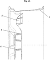
- the connecting surfaces of the two molded parts can be axially ( Fig. 4a ), conical ( Fig. 4b ) and / or via a snap connection ( Fig. 4c ) be aligned with each other.
- the alignment of the two mold parts to each other via spacer segments (7), which are supported by a surface-connected load introduction element (8), which additionally serves to receive the Radverschraubungsetti, and thus accurately position the second mold part (3).
- the wheel also consists of two fiber composite molded parts.
- This is the open cross-section of the spokes on the side facing away from the vehicle, so that the connection of the spoke segments to the rim well can be made over a large area.
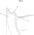
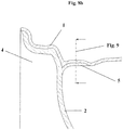
- the spokes are connected by an undercut form fit with the low bed of the rim base, wherein the undercut forming tabs of the spoke segments (5) can be integrated on or in the textile Umflecht Modell the rim base ( Fig. 8a . 8b ).
- this molded part (2) assumes the function of the wheel hub connection surface of the wheel.
- the second molded part (3) is positioned over corresponding spacer segments and thus completely closes the open cross-section of the spoke segments.
- the two mold parts (2, 3) are positively connected to each other via the edges of the spoke profiles and centering (6), whereby a possible adhesive surface is given.
- This embodiment differs from the previous in that the wheel center of a metallic load introduction element (9) and a molded part made of fiber composite material (2) composed.
- the molding with the spoke segments and the hub surface is connected as described in Example 2 with the rim base.
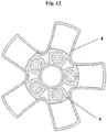
- the metallic load introduction element (9) is characterized by a circumferential wave contour, whereby the element used to receive the Radverschraubungsiata is rotationally integrated between the axially directed portions of the spoke segments and centering of the molded part ( Fig. 12 ).
- the contact surfaces can be used for an additional adhesive bond.
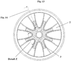
- This exemplary embodiment differs from exemplary embodiment 1 in that both molded parts are joined together with a profile cross-section that is open on the vehicle side, preferably U-profiles ( Figure 13 ).
- the resulting joining zone (10) can be used as an adhesive surface.
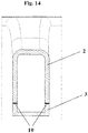
- the joining zone (10) can be carried out such that the connection of both molded parts via a shock ( Figure 14 ) or overlap connection ( Figure 15 ) is realized.
- the undercut, positive connection between the first molded part and the rim base can in this case via the securing shoulder of the rim base (Hump) done ( Fig. 16 ).
Landscapes
- Engineering & Computer Science (AREA)
- Mechanical Engineering (AREA)
- Chemical & Material Sciences (AREA)
- Materials Engineering (AREA)
- Moulding By Coating Moulds (AREA)
- Tires In General (AREA)
- Connection Of Plates (AREA)
- Pulleys (AREA)
Description
- Gegenstand der vorliegenden Erfindung ist ein Radstern mit Profilspeichen, der sich aus mindestens zwei Einzelteilen zusammensetzt, die formschlüssig ineinandergreifen, entsprechend dem Oberbegriff des Anspruchs 1 und wie es aus Dokument
DE 296 23 451 bekannt ist. - Es ist eine Reihe von Konstruktionen bekannt, die Radsterne aus Faserverbundwerkstoffen vorsehen. Diese werden häufig bei der Herstellung anfänglich als Scheibenradstern ausgeführt und nach der Konsolidierung, bspw. mittels CNC-Ausfräsen, mit Aussparungen versehen. Dabei werden naturgemäß die durchgehenden Faserverläufe unterbrochen. Dies wirkt sich nachteilig auf die Festigkeit des Endproduktes aus.
- Die Bauform eines Rades aus Faserverbundwerkstoffen nach
DE 10 2010 010 512 A1 , sieht eine Anbindung des scheibenförmigen Radsterns an das Felgenbett über einen Hinterschnitt vor, der durch Umflechten einer umlaufenden Kontur des Radsterns erfolgt. Die Notwendigkeit einer umlaufenden Kontur führt nachteilig zu Beschränkungen in der Designfreiheit der Radsterne. - Eine weitere bekannte Konstruktion (
DE 10 2006 051 867 A1 ) sieht einen Radstern aus Faserverbundwerkstoff vor, der sich aus ringförmigen aneinander liegenden Speichensegmenten zusammensetzt, die aus umlaufenden unidirektionalen Fasersträngen bestehen, die mittels Wickeltechnologie hergestellt wurden. Dieses Herstellungsverfahren ist sehr aufwendig und erfordert eine Vielzahl unterschiedlicher Arbeitsgänge, die nur schwer zu automatisieren sind. Darüber hinaus weist ein Rad dieser Konstruktion eine nur geringe Crash-Stabilität auf. - Aus der
DE 296 23 451 U1 ist ein Radstern bekannt, welcher zumindest aus zwei miteinander verbundenen Formteilen gebildet wird, wobei die beiden Formteile die Speichen in ihrer radialen Erstreckung vollständig verschließen. - Es stellt sich somit die Aufgabe, eine Radkonstruktion vorzuschlagen, die eine große Designfreiheit bei der Gestaltung des Radsterns bietet, daneben aber die hohen Anforderungen des modernen Automobilbaus an die Crash-Stabilität erfüllt.
- Erfindungsgemäß wird die Aufgabe mit dem Rad nach Anspruch 1 gelöst. Vorteilhafte Ausführungsformen sind in den rückbezogenen Unteransprüchen offenbart.
- Das erfindungsgemäße Rad weist einen Radstern und eine Felge auf, wobei die Felge ihrerseits wieder aus Felgenbett und Felgenhörnern besteht. Bevorzugt besteht das Rad vollständig oder teilweise aus Faserverbundwerkstoff oder Metall. Bevorzugt besteht die Felge vollständig aus Faserverbundwerkstoff oder Metall. Der Radstern besteht aus zwei Formteilen, wobei das erste Formteil die Speichen mit einem offenen Profilquerschnitt ausbildet. Das Rad bzw. das erste Formteil weist dabei zwei, drei oder mehr Speichen auf. Die Speichen weisen eine Profilachse auf, die entlang ihrer Längserstreckung, üblicherweise von der Radnabe zur Felge, verläuft. Das zweite Formteil verschließt den offenen Profilquerschnitt entlang der Profilachsen des ersten Formteils vollständig oder auch nur teilweise. Das erste Formteil besteht bevorzugt aus Faserverbundwerkstoff, während das zweite Formteil aus Faserverbundwerkstoff oder Metall bestehen kann. In einer weiteren bevorzugten Ausführungsform besteht auch das erste Formteil aus Metall, wobei die weiter unten geschilderten Methoden zur Verarbeitung von Faserverbundwerkstoffen durch die entsprechenden, dem Fachmann bekannten Methoden zur Metallverarbeitung (Tiefziehen, Rollen etc.) ersetzt werden. Bevorzugt ist auch die Radnabe in den Radstern integriert und wird von einem der beiden Formteile ausgebildet, ganz besonders bevorzugt bildet das zweite Formteil die Radnabe aus. Weiterhin bevorzugt wird die Radnabe von beiden Formteilen gemeinsam ausgebildet. Bevorzugt sind die Profilquerschnitte des ersten und des zweiten Formteils im Bereich der Speichen U-förmig, wobei die Öffnungen der beiden Formteile einander zu- oder abgewandt sind und der Profilquerschnitt des einen Formteils den des anderen klammerartig umfasst. Besonders bevorzugt umfasst der Profilquerschnitt des ersten Formteils den des zweiten. In weiteren bevorzugten Ausführungsformen greifen die Profilquerschnitte konisch oder eine Klickverbindung ausbildend ineinander oder liegen, eine Stoßverbindung ausbildend, aufeinander.
- Es sind Ausführungsformen bevorzugt, bei denen die Profilachsen an den radial außen liegenden Enden der zweiten Formteile verschlossen sind, so dass sich mindestens ein vollständig abgeschlossener Hohlraum zwischen erstem und zweitem Formteil ausbildet. So wird vorteilhaft eine Verschmutzung des Zwischenraumes zwischen erstem und zweitem Formteil vermieden. Weiterhin bevorzugt sind auch offene Enden der zweiten Formteile, was wiederum vorteilhaft die Kühlung des Radsterns verbessert.
- Die beiden Teile des Radsterns sind dadurch bevorzugt formschlüssig derart miteinander verbunden, dass jeweils die axial gerichteten Bereiche der Profilspeichen sowie des Radnabenflansches ineinandergreifen und somit mindestens eine, typischerweise zwei oder mehr, Berührungsflächen entstehen. Bevorzugt werden die beiden Formteile an diesen Berührungsflächen miteinander verbunden. Diese Verbindung erfolgt vorzugsweise formschlüssig (mittels Rastverbindung der beiden Formteile ineinander) oder stoffschlüssig (mittels Klebeverbindung oder Schweißverbindung). Auch eine Kombination von stoff- und formschlüssiger Verbindung ist möglich.
- Die Anbindung des Radsterns an das Felgenbett erfolgt bevorzugt über eine hinterschnittige Verbindung der Speichensegmente. Bevorzugt werden dabei die Enden der einzelnen Speichen durch Umflechten (Preforming des Felgenbettes mittels des Umflechtverfahrens) formschlüssig mit dem Felgenbett verbunden. Dazu werden die vollständig oder teilweise konsolidierten oder auch unkonsolidierten Enden der Speichensegmente bei der Herstellung des Felgenbettes überflochten. Mit dem Tränken mit Matrixmaterial und dem anschließenden Konsolidieren des Felgenbettes entsteht eine formschlüssige und bei gleichem Matrixmaterial (bzw. chemisch verbindenden Matrixmaterialien) auch eine stoffschlüssige Verbindung mit dem Matrixmaterial des Formteils.
- Die Anbindungsflächen der Speichen an das Felgenbett sind bei einer weiteren bevorzugten Ausführungsform über tangential ein- oder auslaufende Laschen vergrößert. Diese werden bevorzugt ausgebildet, indem die Enden der Speichen parallel zu dem inneren Umfang der Felge umgelegt sind und so abschnittsweise an der Innenseite der Felge verlaufen.
- In einer bevorzugten Ausführungsform weist das erste Formteil die Nabe auf. Diese umgibt ggf. die Achsöffnung und weist die Öffnungen für die Schrauben auf. Das zweite Formteil verschließt den offenen Profilquerschnitt des ersten Formteils vollständig oder teilweise und weist in einer bevorzugten Ausführungsform ebenfalls Schraubenöffnungen auf. Bevorzugt befindet sich zwischen dem erstem und dem zweitem Formteil, sowie die Schraubenlöcher umgebend, mindestens ein Abstandselement aus Metall oder Faserverbundwerkstoff zur Lastaufnahme (Lastaufnahmeelement), das die Anpresskraft der Schrauben aufnimmt. Bevorzugt wird das Abstandselement durch ein flächiges Lastaufnahmeelement (bevorzugt aus Metall) im ersten Formteil positioniert. In einer ganz besonders bevorzugten Ausführungsform besteht das zweite Formteil selbst aus Metall und fungiert als Lastaufnahmeelement, indem es die Anpresskraft der Schrauben aufnimmt. Das zweite Formteil ist dann mindestens um die Schraubenlöcher herum nicht hohl sondern weist durchgehendes Material auf, so dass der Anpressdruck der Schrauben auf beiden Seiten aufgenommen und durch das Formteil abgestützt wird.
- Vorteilhaft können die Speichen beliebige Querschnitte aufweisen, die eine belastungsgerechte Gestaltung des Felgensterns ermöglichen, besonders bevorzugt sind dabei entsprechend ausgeformte U-Profile.
- Das Rad besteht bevorzugt aus faserverstärktem Kunststoff. Als Materialkombinationen kommen vorzugsweise kohlefaserverstärkte Verbundwerkstoffe, bsw. mit Epoxidharz als Matrixmaterial, zum Einsatz. Für Ausführungsformen, die teilweise oder vollständig aus Metall gefertigt werden, sind Stahl, Aluminium, Titan oder Magnesium bzw. die für die Radfertigung aus dem Stand der Technik bekannten Legierungen besonders bevorzugt.
- Die erfindungsgemäße Konstruktion ermöglicht vorteilhaft eine weitere Massereduzierung durch die aufgelöste Speichengeometrie. Weiterhin vorteilhaft besteht keine Notwendigkeit von CNC-Nachbearbeitungen, was die verstärkende Faserstruktur unbeschädigt erhält. So kann eine besonders hohe Crashstabilität des Radsterns erreicht werden.
- Beim ersten Ausführungsbeispiel setzt sich der Radstern aus zwei separaten Formteilen (2, 3) zusammen, welche die Speichensegmente sowie die Radnabe bilden. Die Speichensegmente des ersten Formteils (2) sind fahrzeugseitig durch einen offenen Querschnitt gekennzeichnet. Das Detail X zeigt den Querschnitt einer Speiche, die in dem Bereich, in dem das Formteil 2 die Öffnung im U-förmigen Querschnitt des ersten Formteils (2) nicht verschließt. Im Detail Y ist zu erkennen, wie diese Öffnung in einem anderen Bereich durch das formschlüssig in sie eingreifende, ebenfalls mit U-förmigem Querschnitt ausgebildete zweite Formteil (3) abgedeckt wird. Die Speichen werden axial und radial über einen Formschluss (
Fig. 3 ) in die textile Struktur des Felgenbettes (1) integriert. Den Hinterschnitt bilden die seitlichen, axial gerichteten Bereiche (4) des Speichenquerschnittes, die unterhalb der Tiefbettanbindung an das Felgenbett zur Speichenmittelachse umgeklappt werden und damit eine flächige Anbindung (5) gewährleisten. Die Anschlussfläche bzw. die Radnabe des Radsterns wird durch ein zweites Formteil (3) realisiert, wodurch der Querschnitt der Speichen vollständig geschlossen wird (Fig. 2a , Detail Y). Das zweite Formteil kann dabei derart ausgeführt sein, dass der offene Speichenquerschnitt in radialer Richtung teilweise (Fig. 2a ) oder vollständig bis unterhalb des Felgentiefbettes (Fig. 2b , wobei die Ausführung entsprechend derFigur 2b nicht zum Inhalt der Erfindung zählt) geschlossen ist. Weiterhin können die Speichenenden des zweiten Formteiles derart ausgeführt sein, dass ein abgeschlossener, gegen Medien geschützter Hohlraum zwischen den beiden Formteilen erzeugt wird (Fig. 2c ). Die Anzahl der Speichensegmente ist beliebig. Die beiden Formteile (2, 3) werden formschlüssig über die axial gerichteten Bereiche der Speichenprofile und Mittenzentrierung (6) miteinander verbunden, wodurch eine mögliche Klebefläche gegeben ist. Zur Zentrierung der beiden Formteile können die Verbindungsflächen der beiden Formteile dabei axial (Fig. 4a ), konisch (Fig. 4b ) und/oder über eine Schnappverbindung (Fig. 4c ) zueinander ausgerichtet sein. Zusätzlich erfolgt die Ausrichtung der beiden Formteile zueinander über Abstandssegmente (7), die durch ein flächig angebundenes Lasteinleitungselement (8), welches zusätzlich der Aufnahme der Radverschraubungselemente dient, aufgenommen werden und damit das zweite Formteil (3) exakt positionieren. - Bei diesem Ausführungsbeispiel besteht der Radstern ebenfalls aus zwei Faserverbundwerkstoff-Formteilen. Dabei befindet sich der offene Querschnitt der Speichen auf der fahrzeugabgewandten Seite, so dass die Anbindung der Speichensegmente an das Felgenbett großflächig erfolgen kann. Weiterhin sind die Speichen durch einen hinterschnittigen Formschluss mit dem Tiefbett des Felgenbettes verbunden, wobei die hinterschnittbildenden Laschen der Speichensegmente (5) an oder in die textile Umflechtstruktur des Felgenbettes integriert werden können (
Fig. 8a ,8b ). Gleichzeitig übernimmt dieses Formteil (2) die Funktion der Radnabenanschlussfläche des Rades. Das zweite Formteil (3) wird über entsprechende Abstandssegmente positioniert und schließt damit den offenen Querschnitt der Speichensegmente vollständig. - Die beiden Formteile (2, 3) werden formschlüssig über die Umrandungen der Speichenprofile und Mittenzentrierung (6) miteinander verbunden, wodurch eine mögliche Klebefläche gegeben ist.
- Dieses Ausführungsbeispiel unterscheidet sich gegenüber den Vorigen dahingehend, dass sich der Radstern aus einem metallischen Lasteinleitungselement (9) und einem Formteil aus Faserverbundwerkstoff (2) zusammensetzt. Das Formteil mit den Speichensegmenten und der Radnabenanschlussfläche ist wie im Ausführungsbeispiel 2 beschrieben mit dem Felgenbett verbunden. Das metallische Lasteinleitungselement (9) ist durch eine umlaufende Wellenkontur gekennzeichnet, wodurch das zur Aufnahme der Radverschraubungselemente dienende Element verdrehsicher zwischen den axial gerichteten Bereichen der Speichensegmente und Mittenzentrierung des Formteiles integriert ist (
Fig. 12 ). Die Kontaktflächen können dabei für eine zusätzliche Klebeverbindung genutzt werden. - Dieses Ausführungsbeispiel unterscheidet sich von Ausführungsbeispiel 1 dahingehend, dass beide Formteile mit einem fahrzeugseitig offenen Profilquerschnitt, bevorzugt U-Profile, miteinander gefügt werden (
Fig.13 ). Die dabei entstehende Fügezone (10) kann als Klebefläche genutzt werden. Weiterhin kann die Fügezone (10) derart ausgeführt werden, dass die Verbindung beider Formteile über eine Stoß- (Fig.14 ) oder Überlappungsverbindung (Fig.15 ) realisiert wird. Die hinterschnittige, formschlüssige Verbindung zwischen dem ersten Formteil und dem Felgenbett kann hierbei über die Sicherungsschulter des Felgenbettes (Hump) erfolgen (Fig. 16 ). -
- 1
- Felgenbett
- 2
- Erstes Formteil mit Speichensegmenten
- 3
- Zweites Formteil mit Radnabenanschlussfläche
- 4
- Axial gerichtete Bereiche der Speichensegmente
- 5
- Anbindungslaschen der Speichen an das Felgenbett
- 6
- Axial gerichtete Bereiche der Mittenzentrierung
- 7
- Abstandssegmente aus Faserverbundwerkstoff oder Metall
- 8
- Flächiges Lasteinleitungselement
- 9
- Metallisches Lasteinleitungselement
- 10
- Fügezone
Claims (9)
- Rad, bestehend aus einer Felge mit Felgenbett (1) und einem zweiteiligen Radstern, wobei der Radstern aus zwei Formteilen besteht, wobei ein erstes Formteil (2) die Speichen mit einem offenen Querschnitt ausbildet und das zweite Formteil (3) mit dem ersten Formteil (2) gefügt wird, dadurch gekennzeichnet, dass das zweite Formteil (3) die Speichen des ersten Formteiles (2) in radialer Richtung teilweise entlang der Profillänge verschließt.
- Rad nach Anspruch 1, dadurch gekennzeichnet, dass die Speichen des ersten Formteils (2) eine hinterschnittige, formschlüssige Verbindung mit dem Felgenbett (1) bilden.
- Rad nach Anspruch 1 oder 2, dadurch gekennzeichnet, dass die beiden Formteile (2, 3) des Radsterns über die axial gerichteten Bereiche (4) des Speichenprofils und die Mittenzentrierung formschlüssig miteinander verbunden sind.
- Rad nach einem der vorhergehenden Ansprüche, dadurch gekennzeichnet, dass die beiden Formteile (2, 3) des Radsterns an einander berührenden Flächen oder entlang mindestens einer gemeinsamen Verbindungslinie stoffschlüssig verbunden sind.
- Rad nach einem der vorhergehenden Ansprüche, dadurch gekennzeichnet, dass der offene Querschnitt der Speichen in Richtung Fahrzeugmittelachse oder zur fahrzeugabgewandten Seite zeigt.
- Rad nach einem der vorhergehenden Ansprüche, dadurch gekennzeichnet, dass die seitlichen, axial gerichteten Kontaktflächen der Speichensegmente und/oder die Mittenzentrierung als Klebeflächen ausgeführt sind.
- Rad nach einem der vorhergehenden Ansprüche, dadurch gekennzeichnet, dass die Ausrichtung des zweiten Formteiles (3) über Abstandssegmente (7) erfolgt, die durch ein flächiges Lasteinleitungselement (8), welches vom ersten Formteil (2) aufgenommen wird, positioniert werden.
- Rad nach einem der vorhergehenden Ansprüche, dadurch gekennzeichnet, dass sich der Radstern aus einem ersten Formteil (2) aus Faserverbundwerkstoff und einem metallischem zweiten Formteil (3), dass als Lasteinleitungselement fungiert zusammensetzt, wobei das zweite Formteil (3) mit dem ersten Formteil (2) über die axial gerichteten Bereiche (4) der Speichensegmente und der Mittenzentrierung (6) verdrehsicher verbunden ist.
- Rad nach Anspruch 8, dadurch gekennzeichnet, dass das metallische Lasteinleitungselement (9) die Radnabe ausbildet.
Applications Claiming Priority (2)
| Application Number | Priority Date | Filing Date | Title |
|---|---|---|---|
| DE102012022148.7A DE102012022148B4 (de) | 2012-11-06 | 2012-11-06 | Zweiteiliger Radstern mit Profilspeichen |
| PCT/EP2013/071204 WO2014072151A1 (de) | 2012-11-06 | 2013-10-10 | Zweiteiliger radstern mit profilspeichen |
Publications (2)
| Publication Number | Publication Date |
|---|---|
| EP2917044A1 EP2917044A1 (de) | 2015-09-16 |
| EP2917044B1 true EP2917044B1 (de) | 2018-11-21 |
Family
ID=49378260
Family Applications (1)
| Application Number | Title | Priority Date | Filing Date |
|---|---|---|---|
| EP13777012.9A Active EP2917044B1 (de) | 2012-11-06 | 2013-10-10 | Zweiteiliger radstern mit profilspeichen |
Country Status (8)
| Country | Link |
|---|---|
| US (1) | US9975374B2 (de) |
| EP (1) | EP2917044B1 (de) |
| CN (1) | CN104755274A (de) |
| BR (1) | BR112015005411B1 (de) |
| DE (1) | DE102012022148B4 (de) |
| ES (1) | ES2710933T3 (de) |
| TR (1) | TR201902300T4 (de) |
| WO (1) | WO2014072151A1 (de) |
Families Citing this family (24)
| Publication number | Priority date | Publication date | Assignee | Title |
|---|---|---|---|---|
| DE102011083834A1 (de) * | 2011-09-30 | 2013-04-04 | Washi Kosan Co., Ltd. | Rad |
| WO2015066546A1 (en) | 2013-10-31 | 2015-05-07 | Rodman William L | Composite structures having embedded mechanical features |
| DE102014103608A1 (de) * | 2014-03-17 | 2015-09-17 | Dr. Ing. H.C. F. Porsche Aktiengesellschaft | Rad für ein Kraftfahrzeug |
| DE102015200624A1 (de) * | 2015-01-16 | 2016-07-21 | Bayerische Motoren Werke Aktiengesellschaft | Scheibenrad |
| CN104773030B (zh) * | 2015-04-24 | 2017-05-31 | 李磊 | 一种辐板式车轮及其制作方法 |
| DE102015006652A1 (de) | 2015-05-22 | 2016-04-21 | Audi Ag | Fahrzeugrad sowie Verfahren zur Herstellung eines Fahrzeugrads |
| DE102015211890A1 (de) * | 2015-06-26 | 2016-12-29 | Bayerische Motoren Werke Aktiengesellschaft | Felge für ein Fahrzeug |
| DE102016001114B4 (de) | 2016-02-02 | 2022-05-25 | Audi Ag | Fahrzeugrad sowie Verfahren zur Herstellung eines Fahrzeugrads |
| DE102017104684A1 (de) * | 2016-03-18 | 2017-09-21 | Ksm Castings Group Gmbh | Hybridfelge eines mit einem Radnabenmotor versehenen Rades |
| GB2541498B8 (en) | 2016-06-14 | 2017-11-29 | Dymag Group Ltd | Rim for a wheel |
| RU172328U1 (ru) * | 2016-12-06 | 2017-07-04 | Игорь Владимирович Штурман | Автомобильный диск с отверстиями для крепления дополнительного оборудования |
| USD832179S1 (en) * | 2017-01-13 | 2018-10-30 | Ford Global Technologies, Llc | Vehicle wheel |
| RU178194U1 (ru) * | 2017-06-26 | 2018-03-26 | Игорь Владимирович Штурман | Автомобильный диск с кронштейнами для крепления противобуксовочных средств |
| AU2018313812B2 (en) | 2017-08-08 | 2021-11-11 | Vision Composite Products, Llc | Two piece wheel |
| AU2018317944B2 (en) | 2017-08-18 | 2024-03-07 | Carbon Revolution Pty Ltd | Shaped preform for face portion of a composite wheel |
| CN107901452A (zh) * | 2017-11-15 | 2018-04-13 | 吴波 | 一种复合材料轮毂 |
| RU183439U1 (ru) * | 2018-04-02 | 2018-09-24 | Игорь Владимирович Штурман | Крепежная пластина для автомобильного диска |
| IT201900020436A1 (it) * | 2019-11-05 | 2021-05-05 | Modena Factory S R L | Ruota di supporto per motoveicoli |
| DE102020104305A1 (de) * | 2020-02-19 | 2021-08-19 | Bayerische Motoren Werke Aktiengesellschaft | Rad und Kraftfahrzeug mit Rad |
| CN111845189A (zh) * | 2020-06-16 | 2020-10-30 | 东风汽车车轮随州有限公司 | 一种整体式钢车轮结构 |
| CN114132116B (zh) * | 2021-12-31 | 2024-01-23 | 浙江金固股份有限公司 | 具有挂钩连接件的车轮 |
| US20240066913A1 (en) * | 2022-02-25 | 2024-02-29 | Chet Redman Baigh | Structure Staggered Wheels |
| KR102755418B1 (ko) * | 2022-04-07 | 2025-01-21 | 핸즈코퍼레이션주식회사 | 차량용 휠 |
| DE102023204086A1 (de) * | 2023-05-03 | 2024-11-07 | Volkswagen Aktiengesellschaft | Felge für ein Kraftfahrzeug sowie Verfahren zur Herstellung einer solchen Felge |
Family Cites Families (23)
| Publication number | Priority date | Publication date | Assignee | Title |
|---|---|---|---|---|
| US1470742A (en) * | 1919-05-12 | 1923-10-16 | Budd Wheel Co | Metal wheel |
| US2045902A (en) * | 1932-04-04 | 1936-06-30 | Budd Wheel Co | Composite artillery wheel |
| US3567285A (en) * | 1969-02-10 | 1971-03-02 | Sheller Globe Corp | Simulated magnesium bicycle wheel and method |
| DE7200847U (de) * | 1972-01-11 | 1972-05-04 | Albersinger, Georg, 8091 Atteltal | Kraftfahrzeugfelge in leichtbauweise mit hoher festigkeit |
| FR2516866A1 (fr) | 1978-08-04 | 1983-05-27 | Reynolds Int Inc | Roue composite en aluminium |
| US4316637A (en) | 1978-08-04 | 1982-02-23 | Reynolds Metals Company | Multi-styled aluminum wheel |
| US4256347A (en) * | 1979-10-18 | 1981-03-17 | Reppert Merlyn R | Spoked wheel |
| US4527839A (en) * | 1982-04-30 | 1985-07-09 | Honda Giken Kogyo Kabushiki Kaisha | Synthetic wheel formed from two halves |
| DE3620097A1 (de) * | 1986-06-14 | 1987-12-17 | Suedrad Gmbh | Rad fuer kraftfahrzeuge |
| DE19534522C2 (de) * | 1995-09-06 | 1997-12-18 | Mannesmann Ag | Leichtmetall-Bandrad |
| DE29623451U1 (de) | 1995-10-11 | 1998-07-02 | Dr.Ing.H.C. F. Porsche Ag, 70435 Stuttgart | Rad für ein Kraftfahrzeug |
| DE59603215D1 (de) * | 1995-10-11 | 1999-11-04 | Porsche Ag | Rad für ein Kraftfahrzeug |
| US5782540A (en) * | 1996-05-21 | 1998-07-21 | Brunswick Corporation | Plastic wheel and method of making same |
| WO1998023455A1 (en) | 1996-11-26 | 1998-06-04 | Hayes Wheels International, Inc. | Universal vehicle wheel |
| DE19807943C2 (de) * | 1998-02-25 | 2002-12-12 | Porsche Ag | Rad für ein Fahrzeug, insbesondere Ersatzrad für ein Kraftfahrzeug |
| DE19916444C2 (de) * | 1999-04-12 | 2002-10-31 | Lightcon Gmbh | Rad |
| NL1016108C2 (nl) * | 2000-09-05 | 2002-03-07 | Prins Dokkum B V | Composiet wiel. |
| FR2820685B1 (fr) * | 2001-02-15 | 2003-05-30 | Usinor | Voile de roue emboutie pour l'obtention d'une roue de style |
| DE10130450A1 (de) * | 2001-06-23 | 2003-01-09 | Erfurt Umformtechnik Gmbh | Speichenrad und Verfahren zur Herstellung des Speichenrades |
| US20050104441A1 (en) * | 2003-11-19 | 2005-05-19 | Bertelson Peter C. | Fiber reinforced composite wheels |
| DE102006051867A1 (de) | 2006-10-31 | 2008-05-08 | Theuer, Arwed, Dr.-Ing. | Aus faserverstärktem Kunststoff gewickeltes Rad und Verfahren zu seiner Herstellung |
| DE102010010512B4 (de) | 2010-03-05 | 2022-03-17 | Action Composites Hightech GmbH | Verfahren zur Herstellung einer Radfelge und Verfahren zur Vorfertigung eines Felgenbetts einer Radfelge |
| DE102011087936B3 (de) * | 2011-12-07 | 2013-02-21 | ThyssenKrupp Carbon Components GmbH | Rad aus Faserverbundwerkstoffen und Verfahren zur Herstellung |
-
2012
- 2012-11-06 DE DE102012022148.7A patent/DE102012022148B4/de active Active
-
2013
- 2013-10-10 TR TR2019/02300T patent/TR201902300T4/tr unknown
- 2013-10-10 US US14/430,677 patent/US9975374B2/en not_active Expired - Fee Related
- 2013-10-10 EP EP13777012.9A patent/EP2917044B1/de active Active
- 2013-10-10 BR BR112015005411-0A patent/BR112015005411B1/pt not_active IP Right Cessation
- 2013-10-10 ES ES13777012T patent/ES2710933T3/es active Active
- 2013-10-10 WO PCT/EP2013/071204 patent/WO2014072151A1/de not_active Ceased
- 2013-10-10 CN CN201380056347.1A patent/CN104755274A/zh active Pending
Non-Patent Citations (1)
| Title |
|---|
| None * |
Also Published As
| Publication number | Publication date |
|---|---|
| ES2710933T3 (es) | 2019-04-29 |
| EP2917044A1 (de) | 2015-09-16 |
| TR201902300T4 (tr) | 2019-03-21 |
| DE102012022148A1 (de) | 2014-05-08 |
| BR112015005411B1 (pt) | 2021-07-27 |
| WO2014072151A1 (de) | 2014-05-15 |
| US9975374B2 (en) | 2018-05-22 |
| US20150231917A1 (en) | 2015-08-20 |
| BR112015005411A2 (pt) | 2017-07-04 |
| CN104755274A (zh) | 2015-07-01 |
| DE102012022148B4 (de) | 2024-02-08 |
Similar Documents
| Publication | Publication Date | Title |
|---|---|---|
| EP2917044B1 (de) | Zweiteiliger radstern mit profilspeichen | |
| EP2953783B1 (de) | Rad aus zusammengesetzten speichenelementen | |
| EP2788174B1 (de) | Rad mit radstern und das geeignete herstellungsverfahren | |
| EP2788173B1 (de) | Rad aus faserverbundwerkstoffen und verfahren zur herstellung | |
| EP3019340B1 (de) | Fahrzeugrad und verfahren zur herstellung eines fahrzeugrades | |
| DE102006051867A1 (de) | Aus faserverstärktem Kunststoff gewickeltes Rad und Verfahren zu seiner Herstellung | |
| EP2788199B1 (de) | Zweiteiliges rad | |
| WO2015158780A1 (de) | Fahrzeugrad aus faserverstärktem kunststoff | |
| WO2013083443A1 (de) | Fahrzeug-rad aus faserverstärktem kunststoff | |
| DE102007061954A1 (de) | Bremsscheibe und Verfahren zu deren Herstellung | |
| DE102012102776A1 (de) | Schraubrad für eine elektromechanische lenkvorrichtung | |
| DE102012219903B4 (de) | Radnabe eines Kraftfahrzeugs | |
| EP3585624B1 (de) | Rad aus faserverbundwerkstoff mit galvanischer isolation | |
| DE102012107018B4 (de) | Fahrzeugfelge | |
| DE102017115071B4 (de) | Radlagereinheit | |
| DE102015006652A1 (de) | Fahrzeugrad sowie Verfahren zur Herstellung eines Fahrzeugrads | |
| DE102016207545A1 (de) | Lüfterrad | |
| DE4430489C1 (de) | Rad | |
| DE102016112644B4 (de) | Schneckenrad und Fahrzeug-Lenkvorrichtung mit einem Schneckenrad | |
| DE102010008319B4 (de) | Radnabe aus einem Faserverbundschlauch und Verfahren zum Herstellen einer Radnabe | |
| WO2020038534A2 (de) | Felgensystem mit zentralverschluss sowie sicherungssystem und adapterelement für das felgensystem | |
| EP2823970B1 (de) | Ring für ein Rad sowie Rad mit einem solchen Ring | |
| DE102018113877B3 (de) | Zweiteiliges Rad für ein Fahrzeug | |
| EP3173184B1 (de) | Verfahren zur herstellung eines doppelkonus-synchronrings | |
| EP3424748B1 (de) | Fahrzeugrad |
Legal Events
| Date | Code | Title | Description |
|---|---|---|---|
| PUAI | Public reference made under article 153(3) epc to a published international application that has entered the european phase |
Free format text: ORIGINAL CODE: 0009012 |
|
| 17P | Request for examination filed |
Effective date: 20150202 |
|
| AK | Designated contracting states |
Kind code of ref document: A1 Designated state(s): AL AT BE BG CH CY CZ DE DK EE ES FI FR GB GR HR HU IE IS IT LI LT LU LV MC MK MT NL NO PL PT RO RS SE SI SK SM TR |
|
| AX | Request for extension of the european patent |
Extension state: BA ME |
|
| RIN1 | Information on inventor provided before grant (corrected) |
Inventor name: KOEHLER, CHRISTIAN Inventor name: MAEKE, SANDRO Inventor name: DRESSLER, MICHAEL Inventor name: WERNER, JENS Inventor name: BARTSCH, ANDRE |
|
| DAX | Request for extension of the european patent (deleted) | ||
| GRAP | Despatch of communication of intention to grant a patent |
Free format text: ORIGINAL CODE: EPIDOSNIGR1 |
|
| STAA | Information on the status of an ep patent application or granted ep patent |
Free format text: STATUS: GRANT OF PATENT IS INTENDED |
|
| INTG | Intention to grant announced |
Effective date: 20180111 |
|
| GRAJ | Information related to disapproval of communication of intention to grant by the applicant or resumption of examination proceedings by the epo deleted |
Free format text: ORIGINAL CODE: EPIDOSDIGR1 |
|
| STAA | Information on the status of an ep patent application or granted ep patent |
Free format text: STATUS: REQUEST FOR EXAMINATION WAS MADE |
|
| INTC | Intention to grant announced (deleted) | ||
| GRAP | Despatch of communication of intention to grant a patent |
Free format text: ORIGINAL CODE: EPIDOSNIGR1 |
|
| STAA | Information on the status of an ep patent application or granted ep patent |
Free format text: STATUS: GRANT OF PATENT IS INTENDED |
|
| INTG | Intention to grant announced |
Effective date: 20180626 |
|
| GRAS | Grant fee paid |
Free format text: ORIGINAL CODE: EPIDOSNIGR3 |
|
| GRAA | (expected) grant |
Free format text: ORIGINAL CODE: 0009210 |
|
| STAA | Information on the status of an ep patent application or granted ep patent |
Free format text: STATUS: THE PATENT HAS BEEN GRANTED |
|
| AK | Designated contracting states |
Kind code of ref document: B1 Designated state(s): AL AT BE BG CH CY CZ DE DK EE ES FI FR GB GR HR HU IE IS IT LI LT LU LV MC MK MT NL NO PL PT RO RS SE SI SK SM TR |
|
| REG | Reference to a national code |
Ref country code: CH Ref legal event code: EP |
|
| REG | Reference to a national code |
Ref country code: IE Ref legal event code: FG4D Free format text: LANGUAGE OF EP DOCUMENT: GERMAN |
|
| REG | Reference to a national code |
Ref country code: DE Ref legal event code: R096 Ref document number: 502013011672 Country of ref document: DE |
|
| REG | Reference to a national code |
Ref country code: AT Ref legal event code: REF Ref document number: 1067103 Country of ref document: AT Kind code of ref document: T Effective date: 20181215 |
|
| REG | Reference to a national code |
Ref country code: CH Ref legal event code: NV Representative=s name: FREI PATENTANWALTSBUERO AG, CH |
|
| REG | Reference to a national code |
Ref country code: NL Ref legal event code: MP Effective date: 20181121 |
|
| REG | Reference to a national code |
Ref country code: ES Ref legal event code: FG2A Ref document number: 2710933 Country of ref document: ES Kind code of ref document: T3 Effective date: 20190429 |
|
| PG25 | Lapsed in a contracting state [announced via postgrant information from national office to epo] |
Ref country code: LV Free format text: LAPSE BECAUSE OF FAILURE TO SUBMIT A TRANSLATION OF THE DESCRIPTION OR TO PAY THE FEE WITHIN THE PRESCRIBED TIME-LIMIT Effective date: 20181121 Ref country code: LT Free format text: LAPSE BECAUSE OF FAILURE TO SUBMIT A TRANSLATION OF THE DESCRIPTION OR TO PAY THE FEE WITHIN THE PRESCRIBED TIME-LIMIT Effective date: 20181121 Ref country code: HR Free format text: LAPSE BECAUSE OF FAILURE TO SUBMIT A TRANSLATION OF THE DESCRIPTION OR TO PAY THE FEE WITHIN THE PRESCRIBED TIME-LIMIT Effective date: 20181121 Ref country code: BG Free format text: LAPSE BECAUSE OF FAILURE TO SUBMIT A TRANSLATION OF THE DESCRIPTION OR TO PAY THE FEE WITHIN THE PRESCRIBED TIME-LIMIT Effective date: 20190221 Ref country code: FI Free format text: LAPSE BECAUSE OF FAILURE TO SUBMIT A TRANSLATION OF THE DESCRIPTION OR TO PAY THE FEE WITHIN THE PRESCRIBED TIME-LIMIT Effective date: 20181121 Ref country code: NO Free format text: LAPSE BECAUSE OF FAILURE TO SUBMIT A TRANSLATION OF THE DESCRIPTION OR TO PAY THE FEE WITHIN THE PRESCRIBED TIME-LIMIT Effective date: 20190221 Ref country code: IS Free format text: LAPSE BECAUSE OF FAILURE TO SUBMIT A TRANSLATION OF THE DESCRIPTION OR TO PAY THE FEE WITHIN THE PRESCRIBED TIME-LIMIT Effective date: 20190321 |
|
| PG25 | Lapsed in a contracting state [announced via postgrant information from national office to epo] |
Ref country code: GR Free format text: LAPSE BECAUSE OF FAILURE TO SUBMIT A TRANSLATION OF THE DESCRIPTION OR TO PAY THE FEE WITHIN THE PRESCRIBED TIME-LIMIT Effective date: 20190222 Ref country code: NL Free format text: LAPSE BECAUSE OF FAILURE TO SUBMIT A TRANSLATION OF THE DESCRIPTION OR TO PAY THE FEE WITHIN THE PRESCRIBED TIME-LIMIT Effective date: 20181121 Ref country code: SE Free format text: LAPSE BECAUSE OF FAILURE TO SUBMIT A TRANSLATION OF THE DESCRIPTION OR TO PAY THE FEE WITHIN THE PRESCRIBED TIME-LIMIT Effective date: 20181121 Ref country code: RS Free format text: LAPSE BECAUSE OF FAILURE TO SUBMIT A TRANSLATION OF THE DESCRIPTION OR TO PAY THE FEE WITHIN THE PRESCRIBED TIME-LIMIT Effective date: 20181121 Ref country code: AL Free format text: LAPSE BECAUSE OF FAILURE TO SUBMIT A TRANSLATION OF THE DESCRIPTION OR TO PAY THE FEE WITHIN THE PRESCRIBED TIME-LIMIT Effective date: 20181121 Ref country code: PT Free format text: LAPSE BECAUSE OF FAILURE TO SUBMIT A TRANSLATION OF THE DESCRIPTION OR TO PAY THE FEE WITHIN THE PRESCRIBED TIME-LIMIT Effective date: 20190321 |
|
| PG25 | Lapsed in a contracting state [announced via postgrant information from national office to epo] |
Ref country code: DK Free format text: LAPSE BECAUSE OF FAILURE TO SUBMIT A TRANSLATION OF THE DESCRIPTION OR TO PAY THE FEE WITHIN THE PRESCRIBED TIME-LIMIT Effective date: 20181121 Ref country code: PL Free format text: LAPSE BECAUSE OF FAILURE TO SUBMIT A TRANSLATION OF THE DESCRIPTION OR TO PAY THE FEE WITHIN THE PRESCRIBED TIME-LIMIT Effective date: 20181121 |
|
| REG | Reference to a national code |
Ref country code: DE Ref legal event code: R097 Ref document number: 502013011672 Country of ref document: DE |
|
| PG25 | Lapsed in a contracting state [announced via postgrant information from national office to epo] |
Ref country code: SK Free format text: LAPSE BECAUSE OF FAILURE TO SUBMIT A TRANSLATION OF THE DESCRIPTION OR TO PAY THE FEE WITHIN THE PRESCRIBED TIME-LIMIT Effective date: 20181121 Ref country code: RO Free format text: LAPSE BECAUSE OF FAILURE TO SUBMIT A TRANSLATION OF THE DESCRIPTION OR TO PAY THE FEE WITHIN THE PRESCRIBED TIME-LIMIT Effective date: 20181121 Ref country code: EE Free format text: LAPSE BECAUSE OF FAILURE TO SUBMIT A TRANSLATION OF THE DESCRIPTION OR TO PAY THE FEE WITHIN THE PRESCRIBED TIME-LIMIT Effective date: 20181121 Ref country code: SM Free format text: LAPSE BECAUSE OF FAILURE TO SUBMIT A TRANSLATION OF THE DESCRIPTION OR TO PAY THE FEE WITHIN THE PRESCRIBED TIME-LIMIT Effective date: 20181121 |
|
| PLBE | No opposition filed within time limit |
Free format text: ORIGINAL CODE: 0009261 |
|
| STAA | Information on the status of an ep patent application or granted ep patent |
Free format text: STATUS: NO OPPOSITION FILED WITHIN TIME LIMIT |
|
| 26N | No opposition filed |
Effective date: 20190822 |
|
| PG25 | Lapsed in a contracting state [announced via postgrant information from national office to epo] |
Ref country code: SI Free format text: LAPSE BECAUSE OF FAILURE TO SUBMIT A TRANSLATION OF THE DESCRIPTION OR TO PAY THE FEE WITHIN THE PRESCRIBED TIME-LIMIT Effective date: 20181121 |
|
| REG | Reference to a national code |
Ref country code: DE Ref legal event code: R082 Ref document number: 502013011672 Country of ref document: DE Representative=s name: KAILUWEIT & UHLEMANN PATENTANWAELTE PARTNERSCH, DE |
|
| PG25 | Lapsed in a contracting state [announced via postgrant information from national office to epo] |
Ref country code: MC Free format text: LAPSE BECAUSE OF FAILURE TO SUBMIT A TRANSLATION OF THE DESCRIPTION OR TO PAY THE FEE WITHIN THE PRESCRIBED TIME-LIMIT Effective date: 20181121 |
|
| PG25 | Lapsed in a contracting state [announced via postgrant information from national office to epo] |
Ref country code: LU Free format text: LAPSE BECAUSE OF NON-PAYMENT OF DUE FEES Effective date: 20191010 |
|
| REG | Reference to a national code |
Ref country code: BE Ref legal event code: MM Effective date: 20191031 |
|
| PG25 | Lapsed in a contracting state [announced via postgrant information from national office to epo] |
Ref country code: BE Free format text: LAPSE BECAUSE OF NON-PAYMENT OF DUE FEES Effective date: 20191031 |
|
| PG25 | Lapsed in a contracting state [announced via postgrant information from national office to epo] |
Ref country code: IE Free format text: LAPSE BECAUSE OF NON-PAYMENT OF DUE FEES Effective date: 20191010 |
|
| PGFP | Annual fee paid to national office [announced via postgrant information from national office to epo] |
Ref country code: ES Payment date: 20201228 Year of fee payment: 8 |
|
| PG25 | Lapsed in a contracting state [announced via postgrant information from national office to epo] |
Ref country code: CY Free format text: LAPSE BECAUSE OF FAILURE TO SUBMIT A TRANSLATION OF THE DESCRIPTION OR TO PAY THE FEE WITHIN THE PRESCRIBED TIME-LIMIT Effective date: 20181121 |
|
| PG25 | Lapsed in a contracting state [announced via postgrant information from national office to epo] |
Ref country code: MT Free format text: LAPSE BECAUSE OF FAILURE TO SUBMIT A TRANSLATION OF THE DESCRIPTION OR TO PAY THE FEE WITHIN THE PRESCRIBED TIME-LIMIT Effective date: 20181121 Ref country code: HU Free format text: LAPSE BECAUSE OF FAILURE TO SUBMIT A TRANSLATION OF THE DESCRIPTION OR TO PAY THE FEE WITHIN THE PRESCRIBED TIME-LIMIT; INVALID AB INITIO Effective date: 20131010 |
|
| REG | Reference to a national code |
Ref country code: DE Ref legal event code: R082 Ref document number: 502013011672 Country of ref document: DE Representative=s name: KAILUWEIT & UHLEMANN PATENTANWAELTE PARTNERSCH, DE |
|
| PGFP | Annual fee paid to national office [announced via postgrant information from national office to epo] |
Ref country code: TR Payment date: 20211007 Year of fee payment: 9 Ref country code: GB Payment date: 20211022 Year of fee payment: 9 Ref country code: CZ Payment date: 20211008 Year of fee payment: 9 |
|
| PGFP | Annual fee paid to national office [announced via postgrant information from national office to epo] |
Ref country code: IT Payment date: 20211028 Year of fee payment: 9 Ref country code: FR Payment date: 20211022 Year of fee payment: 9 Ref country code: CH Payment date: 20211020 Year of fee payment: 9 |
|
| PG25 | Lapsed in a contracting state [announced via postgrant information from national office to epo] |
Ref country code: MK Free format text: LAPSE BECAUSE OF FAILURE TO SUBMIT A TRANSLATION OF THE DESCRIPTION OR TO PAY THE FEE WITHIN THE PRESCRIBED TIME-LIMIT Effective date: 20181121 |
|
| REG | Reference to a national code |
Ref country code: ES Ref legal event code: FD2A Effective date: 20230213 |
|
| PG25 | Lapsed in a contracting state [announced via postgrant information from national office to epo] |
Ref country code: ES Free format text: LAPSE BECAUSE OF NON-PAYMENT OF DUE FEES Effective date: 20211011 Ref country code: CZ Free format text: LAPSE BECAUSE OF NON-PAYMENT OF DUE FEES Effective date: 20221010 |
|
| REG | Reference to a national code |
Ref country code: CH Ref legal event code: PL |
|
| GBPC | Gb: european patent ceased through non-payment of renewal fee |
Effective date: 20221010 |
|
| PG25 | Lapsed in a contracting state [announced via postgrant information from national office to epo] |
Ref country code: LI Free format text: LAPSE BECAUSE OF NON-PAYMENT OF DUE FEES Effective date: 20221031 Ref country code: FR Free format text: LAPSE BECAUSE OF NON-PAYMENT OF DUE FEES Effective date: 20221031 Ref country code: CH Free format text: LAPSE BECAUSE OF NON-PAYMENT OF DUE FEES Effective date: 20221031 |
|
| PG25 | Lapsed in a contracting state [announced via postgrant information from national office to epo] |
Ref country code: IT Free format text: LAPSE BECAUSE OF NON-PAYMENT OF DUE FEES Effective date: 20221010 Ref country code: GB Free format text: LAPSE BECAUSE OF NON-PAYMENT OF DUE FEES Effective date: 20221010 |
|
| REG | Reference to a national code |
Ref country code: DE Ref legal event code: R081 Ref document number: 502013011672 Country of ref document: DE Owner name: ACTION COMPOSITES GMBH, AT Free format text: FORMER OWNER: THYSSENKRUPP CARBON COMPONENTS GMBH, 01723 KESSELSDORF, DE |
|
| REG | Reference to a national code |
Ref country code: AT Ref legal event code: PC Ref document number: 1067103 Country of ref document: AT Kind code of ref document: T Owner name: ACTION COMPOSITES GMBH, AT Effective date: 20250120 |
|
| PGFP | Annual fee paid to national office [announced via postgrant information from national office to epo] |
Ref country code: DE Payment date: 20250917 Year of fee payment: 13 |
|
| PGFP | Annual fee paid to national office [announced via postgrant information from national office to epo] |
Ref country code: AT Payment date: 20251021 Year of fee payment: 13 |