EP2917633B1 - Appareil d'éclairage à éclairage de bords - Google Patents
Appareil d'éclairage à éclairage de bords Download PDFInfo
- Publication number
- EP2917633B1 EP2917633B1 EP13852913.6A EP13852913A EP2917633B1 EP 2917633 B1 EP2917633 B1 EP 2917633B1 EP 13852913 A EP13852913 A EP 13852913A EP 2917633 B1 EP2917633 B1 EP 2917633B1
- Authority
- EP
- European Patent Office
- Prior art keywords
- lightguide
- spring
- edge
- leds
- lighting system
- Prior art date
- Legal status (The legal status is an assumption and is not a legal conclusion. Google has not performed a legal analysis and makes no representation as to the accuracy of the status listed.)
- Active
Links
Images


Classifications
-
- G—PHYSICS
- G02—OPTICS
- G02B—OPTICAL ELEMENTS, SYSTEMS OR APPARATUS
- G02B6/00—Light guides; Structural details of arrangements comprising light guides and other optical elements, e.g. couplings
- G02B6/0001—Light guides; Structural details of arrangements comprising light guides and other optical elements, e.g. couplings specially adapted for lighting devices or systems
- G02B6/0011—Light guides; Structural details of arrangements comprising light guides and other optical elements, e.g. couplings specially adapted for lighting devices or systems the light guides being planar or of plate-like form
- G02B6/0081—Mechanical or electrical aspects of the light guide and light source in the lighting device peculiar to the adaptation to planar light guides, e.g. concerning packaging
- G02B6/0086—Positioning aspects
- G02B6/009—Positioning aspects of the light source in the package
-
- F—MECHANICAL ENGINEERING; LIGHTING; HEATING; WEAPONS; BLASTING
- F21—LIGHTING
- F21V—FUNCTIONAL FEATURES OR DETAILS OF LIGHTING DEVICES OR SYSTEMS THEREOF; STRUCTURAL COMBINATIONS OF LIGHTING DEVICES WITH OTHER ARTICLES, NOT OTHERWISE PROVIDED FOR
- F21V19/00—Fastening of light sources or lamp holders
- F21V19/001—Fastening of light sources or lamp holders the light sources being semiconductors devices, e.g. LEDs
- F21V19/0015—Fastening arrangements intended to retain light sources
-
- G—PHYSICS
- G02—OPTICS
- G02B—OPTICAL ELEMENTS, SYSTEMS OR APPARATUS
- G02B6/00—Light guides; Structural details of arrangements comprising light guides and other optical elements, e.g. couplings
- G02B6/0001—Light guides; Structural details of arrangements comprising light guides and other optical elements, e.g. couplings specially adapted for lighting devices or systems
- G02B6/0011—Light guides; Structural details of arrangements comprising light guides and other optical elements, e.g. couplings specially adapted for lighting devices or systems the light guides being planar or of plate-like form
- G02B6/0081—Mechanical or electrical aspects of the light guide and light source in the lighting device peculiar to the adaptation to planar light guides, e.g. concerning packaging
- G02B6/0086—Positioning aspects
- G02B6/0091—Positioning aspects of the light source relative to the light guide
-
- F—MECHANICAL ENGINEERING; LIGHTING; HEATING; WEAPONS; BLASTING
- F21—LIGHTING
- F21S—NON-PORTABLE LIGHTING DEVICES; SYSTEMS THEREOF; VEHICLE LIGHTING DEVICES SPECIALLY ADAPTED FOR VEHICLE EXTERIORS
- F21S8/00—Lighting devices intended for fixed installation
- F21S8/02—Lighting devices intended for fixed installation of recess-mounted type, e.g. downlighters
- F21S8/026—Lighting devices intended for fixed installation of recess-mounted type, e.g. downlighters intended to be recessed in a ceiling or like overhead structure, e.g. suspended ceiling
-
- G—PHYSICS
- G02—OPTICS
- G02B—OPTICAL ELEMENTS, SYSTEMS OR APPARATUS
- G02B6/00—Light guides; Structural details of arrangements comprising light guides and other optical elements, e.g. couplings
- G02B6/0001—Light guides; Structural details of arrangements comprising light guides and other optical elements, e.g. couplings specially adapted for lighting devices or systems
- G02B6/0011—Light guides; Structural details of arrangements comprising light guides and other optical elements, e.g. couplings specially adapted for lighting devices or systems the light guides being planar or of plate-like form
- G02B6/0013—Means for improving the coupling-in of light from the light source into the light guide
-
- G—PHYSICS
- G02—OPTICS
- G02B—OPTICAL ELEMENTS, SYSTEMS OR APPARATUS
- G02B6/00—Light guides; Structural details of arrangements comprising light guides and other optical elements, e.g. couplings
- G02B6/0001—Light guides; Structural details of arrangements comprising light guides and other optical elements, e.g. couplings specially adapted for lighting devices or systems
- G02B6/0011—Light guides; Structural details of arrangements comprising light guides and other optical elements, e.g. couplings specially adapted for lighting devices or systems the light guides being planar or of plate-like form
- G02B6/0066—Light guides; Structural details of arrangements comprising light guides and other optical elements, e.g. couplings specially adapted for lighting devices or systems the light guides being planar or of plate-like form characterised by the light source being coupled to the light guide
- G02B6/0068—Arrangements of plural sources, e.g. multi-colour light sources
-
- G—PHYSICS
- G02—OPTICS
- G02B—OPTICAL ELEMENTS, SYSTEMS OR APPARATUS
- G02B6/00—Light guides; Structural details of arrangements comprising light guides and other optical elements, e.g. couplings
- G02B6/0001—Light guides; Structural details of arrangements comprising light guides and other optical elements, e.g. couplings specially adapted for lighting devices or systems
- G02B6/0011—Light guides; Structural details of arrangements comprising light guides and other optical elements, e.g. couplings specially adapted for lighting devices or systems the light guides being planar or of plate-like form
- G02B6/0066—Light guides; Structural details of arrangements comprising light guides and other optical elements, e.g. couplings specially adapted for lighting devices or systems the light guides being planar or of plate-like form characterised by the light source being coupled to the light guide
- G02B6/0073—Light emitting diode [LED]
-
- G—PHYSICS
- G02—OPTICS
- G02B—OPTICAL ELEMENTS, SYSTEMS OR APPARATUS
- G02B6/00—Light guides; Structural details of arrangements comprising light guides and other optical elements, e.g. couplings
- G02B6/0001—Light guides; Structural details of arrangements comprising light guides and other optical elements, e.g. couplings specially adapted for lighting devices or systems
- G02B6/0011—Light guides; Structural details of arrangements comprising light guides and other optical elements, e.g. couplings specially adapted for lighting devices or systems the light guides being planar or of plate-like form
- G02B6/0075—Arrangements of multiple light guides
- G02B6/0078—Side-by-side arrangements, e.g. for large area displays
-
- F—MECHANICAL ENGINEERING; LIGHTING; HEATING; WEAPONS; BLASTING
- F21—LIGHTING
- F21Y—INDEXING SCHEME ASSOCIATED WITH SUBCLASSES F21K, F21L, F21S and F21V, RELATING TO THE FORM OR THE KIND OF THE LIGHT SOURCES OR OF THE COLOUR OF THE LIGHT EMITTED
- F21Y2115/00—Light-generating elements of semiconductor light sources
- F21Y2115/10—Light-emitting diodes [LED]
Definitions
- Embodiments described herein generally relate to lighting fixtures and, more particularly, to assembly solutions for an edgelit lighting fixture.
- LED Light Emitting Diode
- new lighting fixtures have begun incorporating alternative means for casting, distributing, and reflecting light as compared to conventional fixtures.
- new assembly considerations need to be taken into account for new lighting fixtures, such as edgelit lighting fixtures.
- low tolerances and loose fits facilitate economical manufacturing and service; but on the other hand, high tolerances and tight fits promote optical efficiency and visual appeal. Addressing such competing objectives represents a need in the art.
- embodiments described herein relate to assembly solutions for lighting fixtures, including edgelit fixtures.
- EP 0 846 915 A disclose a lighting unit which gives an extended diffuse effect using light guides around the lamp and with the underside of the light guides provided with a layer of micro-prisms which spread a diffuse light pattern.
- the prisms are arranged so that the light is spread in a defined spread angle with an even intensity.
- the lamp is fitted with reflectors behind and in front with the reflectors having a diffuse reflecting surface.
- EP0846915 , EP1132678 , US2003/007348 relate to lighting fixture comprising two light guides angled relative to one another.
- a lighting system can comprise components that are dimensioned to provide ample tolerance that facilitates economical fabrication, assembly, installation, and service while achieving visual appeal, durability, and optical efficiency.
- the lighting system can comprise a light source and an element that receives, transmits, and emits light produced by the light source.
- the light source comprises one or more LEDs.
- the element that receives, transmits, and emits light comprises a lightguide, for example a lightguide having a generally planar format.
- the light source and the element can be urged together within the lighting system in a manner that takes up, mitigates, or otherwise compensates for the tolerance.
- the urging can come from one or more screws, springs, clips, pins, bands, elastomeric or rubber materials, or other appropriate means that is available.
- FIG. 1 is a perspective view of certain elements of a lighting fixture 10 according to an example not being part of the present invention.
- the lighting fixture 10 comprises a backing tray 400, a reflector 300, a lightguide 200, a light source assembly 202, and a frame 100.
- the lighting fixture 10 can illuminate an area by emitting light that reflects off the reflector 300 outward from a major surface 281 of the lightguide 200.
- the lighting fixture 10 may be installed as a drop-in panel of a suspended ceiling, recessed in a wall or ceiling, or mounted to a surface of a wall or ceiling, for example.
- Light from the light source assembly 202 on the side 291 of the lighting fixture 10 transmits into an edge of the lightguide 200 and scatters, distributes, and/or reflects off the reflector 300, and emits from a major surface of the lightguide 200. More specifically, the coupled light from the light source assembly 202 propagates towards the opposite side 293 of the fixture 10, guided by total internal reflections off the flat major surfaces 281, 282 of the lightguide 200. Portions of the light incident on the flat major surfaces 281, 282 transmit through those surfaces 281, 282. Light transmitting through the major surface 281 is distributed to an area to be lit, for example a room. Light transmitting through the major surface 282 is directed back into the lightguide 200 by the reflector 300, for ultimate emission through the major surface 281.
- the reflector 300 comprises a mirror or specularly reflective surface. In certain embodiments, the reflector 300 comprises a diffusely reflective surface such as a surface coated with flat white paint. In certain embodiments, the reflector 300 is faceted or comprises a surface relief pattern other features that promote reflection.
- the lighting fixture 10 includes one light source, the light source assembly 202, assembled along only one side 291 of the frame 100.
- Other embodiments may include additional light sources similar, substantially identical, or equivalent to the light source assembly 202 along any one, any two, or all three other sides 292, 293, 294 of the frame 100.
- the lighting fixture 10 may vary in shape and size.
- lighting fixtures may be of triangular, square, rectangular, polygonal, circular, or other appropriate shapes.
- the lighting fixture 10 may be formed from various types of suitable materials.
- the frame 100 is formed from a plastic or polymer material
- the lightguide 200 is formed from a plastic, polymer, acrylic, glass, or other suitable material and may include reinforcements such as glass.
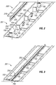
- FIG. 2 is a perspective view of the light source assembly 202 and a section of the frame 100 of the lighting fixture 10.
- the light source assembly 202 includes a bracket 210 and a light source 220.
- the bracket 210 may be formed, for example, from aluminum, or another metal or metal alloy material suitable for the application, or alternatively from appropriate fiberglass or composite materials.
- the light source 220 is mounted or affixed to the bracket 210 using screws, snaps, adhesives, or any other suitable means for the application.
- the bracket 210 supports the light source 220 and also acts as a heat sink to disperse heat from the light source 220 via conduction and/or convection.
- the bracket 210 may comprise heat dissipating fins for thermal management.
- the light source 220 may comprise a rigid printed circuit board (PCB) including electrical circuit traces that electrically couple various components such as LEDs 222 and resistors, for example.
- the LEDs 222 comprise surface mount LEDs that are generally mounted to the PCB at even or regular intervals in a substantially straight line. Alternatively, the LEDs may be irregularly or randomly spaced.
- the light source 220 may include a flexible-type (e.g., tape) circuit in place of a rigid PCB.
- the frame 100 comprises a plurality of spring fingers 102, a plurality of light assembly seats 104, and a plurality of mount posts 106.
- the spring fingers 102 maintain a position of the light source assembly 202 against an edge of the lightguide 200, when the lighting fixture 10 is fully assembled.
- the spring fingers 102 are a type of spring.
- Each spring finger 102 can be molded at respective position on the frame 100 to provide a nominal interference with the bracket 210 of the light source assembly 202 when assembled, causing the light source assembly 202 to be pressed or compressed against the edge of the lightguide 200.
- the spring fingers 102 are provided in pairs as illustrated in FIG.
- a pair of spring fingers 102 may be formed at even intervals, such as every 12 or 24 inches, along the frame 100.
- the spring fingers 102 are located at irregular or random intervals.
- the spring fingers 102 are fastened, welded, glued, or otherwise attached to the main body of the frame 100.
- the spring fingers 102 and the main body of the frame 100 are of like material composition.
- the spring fingers 102 and the frame 100 may be made of different materials, for example one of steel and the other of fiberglass.
- spring finger generally refers to a projection that recovers its position after being bent.
- spring fingers is a plural form of "spring finger.”
- spring as used herein as a noun, generally refers to an elastic element that recovers its original shape when released after being distorted.
- springs as used herein as a noun, is the plural form of "spring.”
- an “elastic" solid is one that is capable of recovering size and shape after deformation.
- the mount posts 106 provide a means for assembling the frame 100 with other elements, such as the light source assembly 202, of the lighting fixture 10.
- the mount posts 106 include a threaded hole to accept a screw for securing the frame 100 to the other elements of the lighting fixture 10.
- each light assembly seat 104 includes a notch 105.
- the light source assembly 202 When the light source assembly 202 is assembled with the frame 100, the light source assembly 202 rests against the light assembly seats 104. When seated upon the lighting assembly seats 104, the light source assembly 202 is provided a limited range of motion in the direction "A", as illustrated.
- the actual position of the light source assembly 202 on the light assembly seats 104 will vary based on the manufacturing tolerances of the frame 100 and the lightguide 200, for example, as described below.
- the range of motion accommodates increased manufacturing tolerance, facilitates assembly during manufacturing, and promotes field service--thereby improving economics on multiple dimensions. Additionally, the system provides tighter joints for better visual appearance and for optical efficiency.
- FIG. 3 is another perspective view of the frame 100 of the lighting fixture 10 according to an example embodiment.
- FIG. 3 illustrates the light source assembly 202 when assembled with the frame 100 as discussed above (i.e., seated upon the light assembly seats 104).
- the light source 220 is aligned and secured in a position against an edge 250 of the lightguide 200. This alignment permits substantially all light from the light source assembly 202 to be emitted into the edge 250 of the lightguide 200.
- FIG. 4 is a cross-section view of the frame 100 of the lighting fixture 10 according to an example embodiment.
- the arrangement of the bracket 210, the light source 220, the LEDs 222 and the spring fingers 102 is illustrated.
- the spring fingers 102 are aligned to press against a back surface of the bracket 210, providing a spring force in the direction "A" toward the edge 250 of the lightguide 200.
- the bracket 210 and the light source 220 rest upon the light assembly seats 104, and an edge of the bracket 210 and an edge of the light source 220 occupy or fit within the notch 105.
- the light source assembly 202 is able to shift or slide in the direction "A" based on the spring force provided by the spring fingers 102, until resting against the edge 250 of the lightguide 200.
- the LEDs 222 contact the edge 250 of the lightguide 200.
- the LEDs 222 are separated from the edge 250 of the lightguide 200 by a gap or standoff distance.
- the light source assembly 202 rests against the edge 250 of the lightguide 200 in a position with a nominal clearance "X" between the LEDs 222 and the edge 250 of the lightguide 200.
- the clearance "X" may be due to one or more elements mounted to the PCB of the light source 220 that are larger than the LEDs 222. That is, the light source 220 includes elements other than the LEDs 222, such as surface mount chip resistors, or one or more shims or spacers, mounted to the PCB of the light source 220.
- these elements may provide a gap, in the form of the nominal clearance "X," between the LEDs 222 and the edge 250 of the lightguide 200. Specifically, these elements may be greater in certain dimensions as compared to the LEDs 222 and contact the edge of the lightguide 200-resulting in the clearance "X” between the LEDs 222 and the edge 250 of the lightguide 200.
- the nominal clearance "X" comprises an intentional standoff of predetermined dimension.
- certain tolerances among the elements of the lighting fixture 10 may be accommodated. That is, certain manufacturing tolerances of the lightguide 200, the frame 100, the light source assembly 202, and other elements may be accommodated. For example, if the lightguide 200 varies for each lighting fixture 10 due to manufacturing tolerances of the lightguide 200, then the spring fingers 102, in connection with the light assembly seats 104, permit the light source assembly 202 to shift a certain distance and rest in a secured position against the edge 250 of the lightguide 200.
- the spring fingers 102 ensure that the light source assembly 202 is secured against the edge 250 of the lightguide 200. Additionally, the nominal clearance "X" may be maintained between the light source 220 and the edge 250 of the lightguide 200 regardless of variances in the size of the lightguide 200 and/or the frame 100.
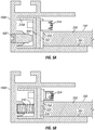
- FIG. 5A is a cross-section view of a frame of a lighting fixture according to another example not being part of the present invention.
- the frame 100A illustrated in FIG. 5A serves a purpose similar to the frame 100 of FIG. 1 but is formed in a different cross sectional shape and, perhaps, from a different material (e.g., from extruded aluminum).
- the light source 220 is mounted to the bracket 210A.
- the bracket 210A serves a purpose similar to the bracket 210 but includes three sides shown in the figure.
- An electrical connector 224 of the light source 220 is also illustrated in FIG. 5A .
- the light source 220 may include the electrical connector 224 or, in some cases, may be connected to power directly using conductive lead lines such as wires.
- the frame 100A extends peripherally about the lightguide 220, i.e. around a perimeter of the lightguide 220.
- the embodiment illustrated in FIG. 5A relies upon the set screw 500 to ensure that the light source 220 and the LEDs 222 mounted to the light source 220 are secured against the edge 250 of the lightguide 200.
- the frame 100A may include one, two, or more set screws 500 along a side. It is noted that, while the spring fingers 102 are formed to automatically provide a spring force upon assembly, the set screw 500 in the example illustrated in FIG. 5A is generally adjusted after initial assembly to provide a desired amount of travel and force to secure the light source 220 against the edge 250 of the lightguide 200.
- the set screw 200, or some other threaded element can be advanced via manual or automated turning.
- the spring fingers 102 discussed above and the set screw 500 represent two examples for urging the light source 220 and the lightguide 200 together.
- FIG. 5B is a cross-section view of a frame of a lighting fixture according to another example not being part of the present invention.
- the embodiment illustrated in FIG. 5B is similar to the example illustrated in FIG. 5A , although incorporating one or more springs 510 in place of the set screws 500 to provide force to secure the light source 220 against the edge 250 of the lightguide 200.
- the springs 510 comprise coils of metal wire.
- the frame 100A may include one, two, or more springs 510 along a side at intervals that may be regular, irregular, or random, for example.
- a spring in the form of a rod of synthetic rubber or some other elastomeric member is substituted for the illustrated coil-based springs 510.
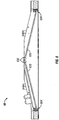
- FIG. 6 is a cross-section view of a lighting fixture 60 according to an embodiment of the present invention.
- the lighting fixture 60 illustrated in FIG. 6 comprises two lightguides 620 aligned in an angled fashion.
- the lightguides 620 extend into the page so that the lighting fixture 60 can be considered roof-shaped.
- Light enters each of the lightguides at the apex of the fixture 60 flows along the lightguide plane, and exits gradually as it flows towards the lower edges. Accordingly, the lighting fixture 60 distributes light downward, softly illuminating a workspace, living area, or elsewhere.
- the lighting fixture 60 includes light assemblies 630 which are similar, in certain aspects, to the light source assembly 202 discussed above. Each light assembly 630 is positioned at an apex edge of a lightguide 620. At edges of the lightguides 620 opposing the light assemblies 630, the lighting fixture 60 includes spring corners 604. The features of the spring corners 604 are further described below with reference to FIGS. 7A and 7B .
- FIG. 7A is a cross-section view of a framing portion of the lighting fixture 60 according to an example embodiment.
- the spring corner 604 comprises a framing section 704 and a spring clip 720, which is another example embodiment of a spring.
- the framing section 704 may be formed from aluminum, plastic, or other suitable materials
- the spring clip 720 may be formed from steel, shape-memory metal alloys suitable for the application, or other suitable material or materials.
- spring corner generally refers to a corner in which or at which at least one spring is disposed.
- spring corners as used herein, is the plural form of "spring corner.”
- spring clip generally refers to a spring that grips, clasps, or hooks.
- spring clips as used herein, is the plural form of "spring clip.”
- the spring clip 720 urges the lightguide 620 against the light assemblies 630.
- a gap may separate the lightguide edge from the LEDs.
- a circuit board may include a standoff, in the form of a shim (made of metal or electrically nonconductive material, for example) or a standard electrical component (such as a resistor or capacitor, for example).
- the LEDs and the light lightguide edge may be in physical contact with one another.
- the framing section 704 includes a recess or void in which the spring clip 720 is secured. It is noted that both the framing section 704 and the spring clip 720 may extend a certain distance orthogonal to the direction of the cross-section illustrated in FIG. 7A . In certain embodiments, the spring clip 720 extends orthogonally "into the page" essentially the full length of a side the fixture 60. In certain embodiments, multiple spring clips 720 are incorporated at regular, irregular, or random intervals, for example. In certain embodiments, there are four small spring clips 720, one in each corner of the frame, that apply pressure to the light guides (such that there are two spring clips per lightguide).
- a base 722 of the spring clip 720 is positioned within the recess of the framing section 704 so as to hinder the base 722 of the spring clip 720 from rotating or moving.
- the spring clip 720 is formed such that the arm 724 of the spring clip 720 is biased to maintain a certain angle with respect to the base 722.
- the arm 724 provides a force in the direction "B", as illustrated.
- the spring clip 720 may act as a leaf spring it its compression method. Before being fully assembled with the lightguide 620, the arm 724 of the spring clip 720 generally rotates in the direction B until contacting the screw 712 which prevents further movement. In certain embodiments, rather than contacting the screw 712 contact is with the back wall, and once in contact with the back wall the spring clip 720 compresses like a leaf spring.
- FIG. 7B is another cross-section view of a framing portion of the lighting fixture 60 according to an example embodiment.
- the lightguide 620 has been installed with the lighting fixture 60.
- an edge 650 of the lightguide 620 extends into the recess of the framing section 704 and contacts the arm 724 of the spring clip 720.
- the spring clip 720 provides a force against the edge 650 in the direction B. This force results in application of a translated force on an opposing edge of the lightguide 620 -- the edge where a light assembly 630 is mounted.
- the entire lightguide 620 is pushed by the spring clip 720 to secure the lightguide 620 against the light assembly 630. This permits substantially all light from the light assembly 630 to be emitted into the edge of the lightguide 620 and accommodates fabrication tolerance as discussed above.
Landscapes
- Physics & Mathematics (AREA)
- General Physics & Mathematics (AREA)
- Optics & Photonics (AREA)
- Engineering & Computer Science (AREA)
- General Engineering & Computer Science (AREA)
- Microelectronics & Electronic Packaging (AREA)
- Planar Illumination Modules (AREA)
- Non-Portable Lighting Devices Or Systems Thereof (AREA)
- Fastening Of Light Sources Or Lamp Holders (AREA)
Claims (10)
- Système d'éclairage (60) comprenant :
un premier guide de lumière (620) comprenant :deux premières surfaces principales (281, 282) ;un premier bord sommital formé entre les deux premières surfaces principales (281, 282) ; etun premier bord inférieur (650) formé entre les deux première surfaces principales (281, 282) ;une ou plusieurs premières DEL (222) disposées le long du premier bord sommital pour coupler la lumière dans le premier guide de lumière (620) à travers le premier bord sommital ;un second guide de lumière (620) comprenant :deux secondes surfaces principales (281, 282) ;un second bord sommital formé entre les deux secondes surfaces principales (281, 282) ; etun second bord inférieur (650) formé entre les deux secondes surfaces principales (281, 828) ;une ou plusieurs secondes DEL (222) disposées le long du second bord sommital pour coupler la lumière dans le second guide de lumière (620) à travers le second bord sommital ; etun cadre ;dans lequel le premier guide de lumière (620) et le second guide de lumière (620) sont inclinés l'un par rapport à l'autre pour fournir un sommet au premier bord sommital et au second bord sommital, le cadre étant configuré pour être installé de manière encastrée dans un plafond ; caractérisé en ce quele cadre comprend un premier renfoncement qui reçoit et soutient le premier bord inférieur (650) du premier guide de lumière (620) et comprend un second renfoncement qui reçoit et soutient le second bord inférieur (650) du second guide de lumière (620) ;et en ce queau moins un premier ressort (720) étant disposé dans le premier renfoncement et en contact avec le premier bord inférieur (650) du premier guide de lumière (620) ; etau moins un second ressort (720) étant disposé dans le second renfoncement et en contact avec le second bord inférieur (650) du second guide de lumière (620). - Système d'éclairage (60) selon la revendication 1, dans lequel le premier ressort (720) pousse la ou les premières DEL (222) et le premier bord sommital du premier guide de lumière ensemble,
dans lequel une entretoise fournit un espace entre la ou les premières DEL (222) et le premier bord sommital qui sont poussés ensemble par le premier ressort (720). - Système d'éclairage (60) selon la revendication 1, dans lequel au moins l'une parmi la ou les secondes DEL (222) est poussée de manière à entrer en contact avec le second bord sommital du second guide de lumière (620) par le second ressort (720).
- Système d'éclairage (60) selon la revendication 1, dans lequel le cadre (100) comprend :une partie formant cadre (704) qui comprend le premier renfoncement dans lequel le premier bord inférieur (650) du premier guide de lumière (620) est disposé ; etune seconde partie formant cadre (704) qui comprend le second renfoncement dans lequel le second bord inférieur (650) du second guide de lumière (620) est disposé,dans lequel le premier ressort (720) comprend une première base (722) et un premier bras (724) s'étendant à partir de la première base (722) ; etdans lequel le second ressort (720) comprend une seconde base (722) et un second bras (724) s'étendant à partir de la seconde base (722),dans lequel la première base (722) du premier ressort (720) est positionnée à l'intérieur du premier renfoncement de la première partie formant cadre (704) de manière à empêcher la première base (722) du premier ressort (720) de pivoter ou de se déplacer,dans lequel le premier bras (724) du premier ressort (720) pousse le premier bord inférieur (650) du premier guide de lumière (620) à fixer le premier bord sommital du premier guide de lumière (620) contre la ou les premières DEL (222),dans lequel la seconde base (722) du second ressort (720) est positionnée à l'intérieur du second renfoncement de la seconde partie formant cadre (704) de manière à empêcher la seconde base (722) du second ressort (720) de pivoter ou de se déplacer, etdans lequel le second bras (724) du second ressort (720) pousse le second bord inférieur (650) du second guide de lumière (620) à fixer le second bord sommital du second guide de lumière (620) contre la ou les secondes DEL (222).
- Système d'éclairage (60) selon la revendication 4, dans lequel le premier ressort (720) fonctionne comme un premier ressort à lames et le second ressort (720) fonctionne comme un second ressort à lames.
- Système d'éclairage (60) selon la revendication 5, dans lequel le premier ressort (720) s'étend le long d'un premier côté du système d'éclairage (60) et le second ressort (720) s'étend le long d'un second côté du système d'éclairage (60).
- Système d'éclairage (60) selon la revendication 1, dans lequel une entretoise qui est montée sur un circuit imprimé maintient une séparation prédéfinie entre la ou les premières DEL (222) et le premier bord sommital, l'entretoise comprenant un composant électrique.
- Système d'éclairage (60) selon la revendication 1, dans lequel un premier réflecteur est disposé au-dessus du premier guide de lumière (620) et le premier guide de lumière (620) répartit la lumière à travers l'une des deux premières surfaces principales (281, 282), et
dans lequel un second réflecteur est disposé au-dessus du second guide de lumière (620) et le second guide de lumière (620) répartit la lumière à travers l'une des deux secondes surfaces principales (281, 282). - Système d'éclairage (60) selon la revendication 1, dans lequel au moins l'une parmi la ou les premières DEL (222) est poussée de manière à entrer en contact avec le premier bord sommital par le premier ressort (720), le premier ressort (720) étant formé à partir d'un alliage à mémoire de forme.
- Système d'éclairage (60) selon la revendication 1, dans lequel la ou les premières DEL (222) disposées le long du premier bord sommital sont en contact avec le premier bord sommital.
Applications Claiming Priority (3)
| Application Number | Priority Date | Filing Date | Title |
|---|---|---|---|
| US201261723587P | 2012-11-07 | 2012-11-07 | |
| US13/788,827 US9110216B2 (en) | 2012-11-07 | 2013-03-07 | Edgelit lighting fixture and assembly |
| PCT/US2013/068781 WO2014074618A1 (fr) | 2012-11-07 | 2013-11-06 | Appareil et ensemble d'éclairage à éclairage de bords |
Publications (3)
| Publication Number | Publication Date |
|---|---|
| EP2917633A1 EP2917633A1 (fr) | 2015-09-16 |
| EP2917633A4 EP2917633A4 (fr) | 2016-07-20 |
| EP2917633B1 true EP2917633B1 (fr) | 2022-01-05 |
Family
ID=50622207
Family Applications (1)
| Application Number | Title | Priority Date | Filing Date |
|---|---|---|---|
| EP13852913.6A Active EP2917633B1 (fr) | 2012-11-07 | 2013-11-06 | Appareil d'éclairage à éclairage de bords |
Country Status (5)
| Country | Link |
|---|---|
| US (4) | US9110216B2 (fr) |
| EP (1) | EP2917633B1 (fr) |
| CN (1) | CN104919242B (fr) |
| AU (1) | AU2013341225B2 (fr) |
| WO (1) | WO2014074618A1 (fr) |
Families Citing this family (22)
| Publication number | Priority date | Publication date | Assignee | Title |
|---|---|---|---|---|
| KR20130109732A (ko) * | 2012-03-28 | 2013-10-08 | 삼성전자주식회사 | 백라이트 유닛 및 이를 구비한 영상 표시 장치 |
| US9666744B2 (en) | 2013-03-15 | 2017-05-30 | Cooper Technologies Company | Edgelit multi-panel lighting system |
| JP5666645B2 (ja) * | 2013-03-26 | 2015-02-12 | シャープ株式会社 | バックライト装置およびそれを備えた液晶表示装置 |
| USD701988S1 (en) * | 2013-04-22 | 2014-04-01 | Cooper Technologies Company | Multi-panel edgelit luminaire |
| KR102131274B1 (ko) * | 2013-06-28 | 2020-07-07 | 엘지이노텍 주식회사 | 조명 유닛 |
| KR102080195B1 (ko) * | 2013-07-23 | 2020-02-21 | 엘지이노텍 주식회사 | 조명장치 및 상기 조명장치를 포함하는 표시장치 |
| US9521727B1 (en) | 2014-05-30 | 2016-12-13 | Cooper Technologies Company | Lighting fixture with motion sensor and battery test switch |
| US10253956B2 (en) | 2015-08-26 | 2019-04-09 | Abl Ip Holding Llc | LED luminaire with mounting structure for LED circuit board |
| US9964692B2 (en) * | 2015-10-06 | 2018-05-08 | Focal Point, Llc | Illuminated feature for an LED luminaire |
| CN107304979B (zh) * | 2016-04-22 | 2020-05-15 | 纳米格有限公司 | 可配置的扁平照明装置 |
| USD841869S1 (en) * | 2016-09-28 | 2019-02-26 | Ningbo Royalux Lighting Co., Ltd. | Light-emitting diode pendant lamp |
| USD848659S1 (en) * | 2017-03-22 | 2019-05-14 | Ningbo Royalux Lighting Co., Ltd. | Light-emitting diode pendant lamp |
| US11112556B2 (en) * | 2017-05-27 | 2021-09-07 | Nulite Lighting | Edge-lit lighting fixtures |
| US10251279B1 (en) | 2018-01-04 | 2019-04-02 | Abl Ip Holding Llc | Printed circuit board mounting with tabs |
| WO2019213201A1 (fr) | 2018-05-01 | 2019-11-07 | Hubbell Incorporated | Appareil d'éclairage |
| MX2019005086A (es) | 2018-05-01 | 2019-11-04 | Hubbell Inc | Dispositivo de iluminacion. |
| USD908271S1 (en) | 2018-05-01 | 2021-01-19 | Hubbell Incorporated | Lighting fixture |
| DE102019111593A1 (de) * | 2019-05-06 | 2020-11-12 | Zumtobel Lighting Gmbh | Längliche Leuchte |
| CN114174905A (zh) * | 2019-06-26 | 2022-03-11 | 康宁公司 | 显示设备及其背光单元 |
| CN114383374B (zh) * | 2020-10-21 | 2025-08-01 | 博西华电器(江苏)有限公司 | 用于制冷器具的照明模块和制冷器具 |
| JP7497534B2 (ja) | 2021-05-27 | 2024-06-10 | シグニファイ ホールディング ビー ヴィ | ライトガイド要素を有する照明構成 |
| DE102024118382A1 (de) * | 2024-05-31 | 2025-12-04 | Liebherr-Hausgeräte Ochsenhausen GmbH | Kühl- und/oder Gefriergerät |
Citations (3)
| Publication number | Priority date | Publication date | Assignee | Title |
|---|---|---|---|---|
| EP1132678A1 (fr) * | 2000-03-10 | 2001-09-12 | Siteco Beleuchtungstechnik GmbH | Luminaire avec guide de lumière creux symétrique situé au centre et irradiation symétrique, en particulier luminaire circulaire |
| US20030007348A1 (en) * | 2000-02-14 | 2003-01-09 | Zumobel Staff Gmbh | Luminaire |
| US20120105762A1 (en) * | 2010-11-03 | 2012-05-03 | Shenzhen China Star Optoelectronics Technology Co., Ltd. | Edge-lit backlight module and liquid crystal display |
Family Cites Families (30)
| Publication number | Priority date | Publication date | Assignee | Title |
|---|---|---|---|---|
| US4789224A (en) * | 1987-05-04 | 1988-12-06 | General Motors Corporation | Instrument panel having light pipe having legs |
| JP2538667B2 (ja) * | 1989-04-13 | 1996-09-25 | 富士通株式会社 | バックライト |
| DE59713046D1 (de) * | 1996-12-04 | 2010-11-18 | Siteco Beleuchtungstech Gmbh | Innenraumleuchte |
| GB9819196D0 (en) * | 1998-09-04 | 1998-10-28 | Ici Plc | Edge-lit illumination system |
| US6161939A (en) * | 1999-05-05 | 2000-12-19 | Semperlux Ag | Interior lighting fixture |
| RU2179935C1 (ru) | 2000-06-22 | 2002-02-27 | Открытое акционерное общество "Калужский завод автомобильного электрооборудования" | Стеклоомыватель с приводом из сплава с памятью формы |
| US6697130B2 (en) * | 2001-01-16 | 2004-02-24 | Visteon Global Technologies, Inc. | Flexible led backlighting circuit |
| US6802628B2 (en) * | 2002-10-18 | 2004-10-12 | Heng Huang Kuo | Vertically downward type back-light module |
| TWM270369U (en) * | 2004-11-26 | 2005-07-11 | Innolux Display Corp | Back light module and liquid crystal display device |
| TWM269470U (en) * | 2004-12-31 | 2005-07-01 | Innolux Display Corp | Back light module |
| US7473022B2 (en) | 2005-10-26 | 2009-01-06 | Fawoo Technology Co., Ltd. | Backlight unit capable of easily forming curved and three-dimensional shape |
| TWI315015B (en) * | 2005-11-18 | 2009-09-21 | Innolux Display Corp | Backlight module and liquid crystal display device |
| US7547112B2 (en) * | 2005-12-12 | 2009-06-16 | Led Folio Corporation | Low-clearance light emitting diode lighting |
| CN101000433A (zh) * | 2006-01-12 | 2007-07-18 | 鸿富锦精密工业(深圳)有限公司 | 背光模组 |
| US8147113B2 (en) * | 2007-01-22 | 2012-04-03 | Sharp Kabushiki Kaisha | Backlight device and flat display using it |
| US7918600B2 (en) * | 2007-08-09 | 2011-04-05 | Panasonic Corporation | Planar illumination device and liquid crystal display device using the same |
| JP5414224B2 (ja) * | 2007-10-19 | 2014-02-12 | 富士フイルム株式会社 | 面状照明装置 |
| JP4618310B2 (ja) * | 2008-03-19 | 2011-01-26 | エプソンイメージングデバイス株式会社 | 照明装置、照明装置の組立て方法及び液晶表示装置 |
| EP2192430B1 (fr) * | 2008-11-27 | 2016-04-06 | Samsung Electronics Co., Ltd. | Dispositif de rétroéclairage |
| EP2431653A4 (fr) | 2009-07-23 | 2013-10-30 | Sharp Kk | Dispositif d éclairage et dispositif d affichage |
| US20120120326A1 (en) * | 2009-07-30 | 2012-05-17 | Sharp Kabushiki Kaisha | Edge-light illuminating device, liquid crystal display device and television receiving device |
| KR101028210B1 (ko) * | 2010-03-26 | 2011-04-11 | 엘지이노텍 주식회사 | 도광판 및 이를 구비한 백라이트 유닛 |
| KR20120084369A (ko) * | 2011-01-20 | 2012-07-30 | 엘지전자 주식회사 | 코너 광원부를 갖는 백라이트 유닛 |
| DE202011003171U1 (de) * | 2011-02-24 | 2011-05-05 | Weyer, Andreas | Einbaurahmen für eine Leuchtvorrichtung und Leuchtvorrichtung |
| JP4991013B1 (ja) * | 2011-02-28 | 2012-08-01 | シャープ株式会社 | 照明器具 |
| US8794811B2 (en) * | 2011-03-16 | 2014-08-05 | GE Lighting Solutions, LLC | Edge-illuminated flat panel and light module for same |
| US8770816B2 (en) * | 2011-05-13 | 2014-07-08 | Rambus Delaware Llc | Lighting assembly |
| KR101191748B1 (ko) * | 2011-09-28 | 2012-10-15 | 명범영 | 대형 도광판의 열팽창을 탄력적으로 완충할 수 있는 구조로 된 백라이트 장치 |
| US8690412B2 (en) * | 2012-03-15 | 2014-04-08 | Apple Inc. | Backlight structures and backlight assemblies for electronic device displays |
| US8944662B2 (en) * | 2012-08-13 | 2015-02-03 | 3M Innovative Properties Company | Diffractive luminaires |
-
2013
- 2013-03-07 US US13/788,827 patent/US9110216B2/en active Active
- 2013-11-06 AU AU2013341225A patent/AU2013341225B2/en active Active
- 2013-11-06 EP EP13852913.6A patent/EP2917633B1/fr active Active
- 2013-11-06 CN CN201380069330.XA patent/CN104919242B/zh active Active
- 2013-11-06 WO PCT/US2013/068781 patent/WO2014074618A1/fr not_active Ceased
-
2015
- 2015-07-31 US US14/815,288 patent/US10042113B2/en active Active
-
2018
- 2018-08-06 US US16/056,299 patent/US10473850B2/en active Active
-
2019
- 2019-11-11 US US16/680,239 patent/US20200081175A1/en not_active Abandoned
Patent Citations (3)
| Publication number | Priority date | Publication date | Assignee | Title |
|---|---|---|---|---|
| US20030007348A1 (en) * | 2000-02-14 | 2003-01-09 | Zumobel Staff Gmbh | Luminaire |
| EP1132678A1 (fr) * | 2000-03-10 | 2001-09-12 | Siteco Beleuchtungstechnik GmbH | Luminaire avec guide de lumière creux symétrique situé au centre et irradiation symétrique, en particulier luminaire circulaire |
| US20120105762A1 (en) * | 2010-11-03 | 2012-05-03 | Shenzhen China Star Optoelectronics Technology Co., Ltd. | Edge-lit backlight module and liquid crystal display |
Also Published As
| Publication number | Publication date |
|---|---|
| AU2013341225A1 (en) | 2015-06-18 |
| US10473850B2 (en) | 2019-11-12 |
| CN104919242B (zh) | 2019-03-12 |
| US20140126243A1 (en) | 2014-05-08 |
| US10042113B2 (en) | 2018-08-07 |
| EP2917633A4 (fr) | 2016-07-20 |
| CN104919242A (zh) | 2015-09-16 |
| EP2917633A1 (fr) | 2015-09-16 |
| US20150378081A1 (en) | 2015-12-31 |
| WO2014074618A1 (fr) | 2014-05-15 |
| AU2013341225B2 (en) | 2017-09-28 |
| US9110216B2 (en) | 2015-08-18 |
| US20180341054A1 (en) | 2018-11-29 |
| US20200081175A1 (en) | 2020-03-12 |
Similar Documents
| Publication | Publication Date | Title |
|---|---|---|
| EP2917633B1 (fr) | Appareil d'éclairage à éclairage de bords | |
| CN102016676B (zh) | 透镜体、光源单元和照明装置 | |
| JP6345749B2 (ja) | 照明装置 | |
| US20130336008A1 (en) | Lighting Device | |
| US10060608B2 (en) | Detachable LED lighting device | |
| CN213920834U (zh) | 车灯系统和车辆 | |
| CN105121949A (zh) | 具有导光面板的led灯具 | |
| JP6315757B2 (ja) | 照明器具 | |
| US9441816B2 (en) | Lighting arrangement having a resilient element | |
| CN104456164A (zh) | 一种照明组件 | |
| CN203500896U (zh) | 一种照明组件 | |
| JP6762400B2 (ja) | Led光源ユニット、本体ユニット、及びled照明器具 | |
| JP5597592B2 (ja) | 発光部材及びこれを備えた照明装置 | |
| EP4348100B1 (fr) | Agencement d'éclairage ayant un élément de guidage de lumière | |
| CN210532308U (zh) | 一种应用于灯具的安装组件及其灯具 | |
| WO2012157145A1 (fr) | Dispositif d'éclairage | |
| KR100863979B1 (ko) | 파라볼릭 엘이디 조명등 | |
| JP5919551B2 (ja) | Led照明器具およびルーバー | |
| KR102387800B1 (ko) | 평판형 조명장치 | |
| JP2015141763A (ja) | 照明器具 | |
| JP2023105879A (ja) | 灯具、照明装置および透光カバー | |
| KR200488640Y1 (ko) | 조명용 프로파일 및 이를 포함하는 led 조명 기구 | |
| JP2024103105A (ja) | 照明装置、照明器具及び照明装置の製造方法 | |
| WO2025042445A1 (fr) | Persiennes externes pour luminaire linéaire | |
| JP2024087189A (ja) | 照明装置及び照明器具 |
Legal Events
| Date | Code | Title | Description |
|---|---|---|---|
| PUAI | Public reference made under article 153(3) epc to a published international application that has entered the european phase |
Free format text: ORIGINAL CODE: 0009012 |
|
| 17P | Request for examination filed |
Effective date: 20150602 |
|
| AK | Designated contracting states |
Kind code of ref document: A1 Designated state(s): AL AT BE BG CH CY CZ DE DK EE ES FI FR GB GR HR HU IE IS IT LI LT LU LV MC MK MT NL NO PL PT RO RS SE SI SK SM TR |
|
| AX | Request for extension of the european patent |
Extension state: BA ME |
|
| DAX | Request for extension of the european patent (deleted) | ||
| RA4 | Supplementary search report drawn up and despatched (corrected) |
Effective date: 20160621 |
|
| RIC1 | Information provided on ipc code assigned before grant |
Ipc: F21V 19/00 20060101ALI20160615BHEP Ipc: F21S 8/02 20060101ALI20160615BHEP Ipc: F21S 4/00 20160101AFI20160615BHEP Ipc: F21V 8/00 20060101ALI20160615BHEP |
|
| STAA | Information on the status of an ep patent application or granted ep patent |
Free format text: STATUS: EXAMINATION IS IN PROGRESS |
|
| 17Q | First examination report despatched |
Effective date: 20171220 |
|
| RAP1 | Party data changed (applicant data changed or rights of an application transferred) |
Owner name: EATON INTELLIGENT POWER LIMITED |
|
| RAP1 | Party data changed (applicant data changed or rights of an application transferred) |
Owner name: SIGNIFY HOLDING B.V. |
|
| GRAP | Despatch of communication of intention to grant a patent |
Free format text: ORIGINAL CODE: EPIDOSNIGR1 |
|
| STAA | Information on the status of an ep patent application or granted ep patent |
Free format text: STATUS: GRANT OF PATENT IS INTENDED |
|
| INTG | Intention to grant announced |
Effective date: 20210624 |
|
| RIN1 | Information on inventor provided before grant (corrected) |
Inventor name: BLESSITT, JAMES H. Inventor name: CLEMENTS, RUSS Inventor name: PATRICK, ELLIS W. |
|
| GRAS | Grant fee paid |
Free format text: ORIGINAL CODE: EPIDOSNIGR3 |
|
| GRAA | (expected) grant |
Free format text: ORIGINAL CODE: 0009210 |
|
| STAA | Information on the status of an ep patent application or granted ep patent |
Free format text: STATUS: THE PATENT HAS BEEN GRANTED |
|
| AK | Designated contracting states |
Kind code of ref document: B1 Designated state(s): AL AT BE BG CH CY CZ DE DK EE ES FI FR GB GR HR HU IE IS IT LI LT LU LV MC MK MT NL NO PL PT RO RS SE SI SK SM TR |
|
| REG | Reference to a national code |
Ref country code: GB Ref legal event code: FG4D |
|
| REG | Reference to a national code |
Ref country code: CH Ref legal event code: EP |
|
| REG | Reference to a national code |
Ref country code: AT Ref legal event code: REF Ref document number: 1460900 Country of ref document: AT Kind code of ref document: T Effective date: 20220115 |
|
| REG | Reference to a national code |
Ref country code: DE Ref legal event code: R096 Ref document number: 602013080624 Country of ref document: DE |
|
| REG | Reference to a national code |
Ref country code: IE Ref legal event code: FG4D |
|
| REG | Reference to a national code |
Ref country code: LT Ref legal event code: MG9D |
|
| REG | Reference to a national code |
Ref country code: NL Ref legal event code: MP Effective date: 20220105 |
|
| REG | Reference to a national code |
Ref country code: AT Ref legal event code: MK05 Ref document number: 1460900 Country of ref document: AT Kind code of ref document: T Effective date: 20220105 |
|
| PG25 | Lapsed in a contracting state [announced via postgrant information from national office to epo] |
Ref country code: NL Free format text: LAPSE BECAUSE OF FAILURE TO SUBMIT A TRANSLATION OF THE DESCRIPTION OR TO PAY THE FEE WITHIN THE PRESCRIBED TIME-LIMIT Effective date: 20220105 |
|
| PG25 | Lapsed in a contracting state [announced via postgrant information from national office to epo] |
Ref country code: SE Free format text: LAPSE BECAUSE OF FAILURE TO SUBMIT A TRANSLATION OF THE DESCRIPTION OR TO PAY THE FEE WITHIN THE PRESCRIBED TIME-LIMIT Effective date: 20220105 Ref country code: RS Free format text: LAPSE BECAUSE OF FAILURE TO SUBMIT A TRANSLATION OF THE DESCRIPTION OR TO PAY THE FEE WITHIN THE PRESCRIBED TIME-LIMIT Effective date: 20220105 Ref country code: PT Free format text: LAPSE BECAUSE OF FAILURE TO SUBMIT A TRANSLATION OF THE DESCRIPTION OR TO PAY THE FEE WITHIN THE PRESCRIBED TIME-LIMIT Effective date: 20220505 Ref country code: NO Free format text: LAPSE BECAUSE OF FAILURE TO SUBMIT A TRANSLATION OF THE DESCRIPTION OR TO PAY THE FEE WITHIN THE PRESCRIBED TIME-LIMIT Effective date: 20220405 Ref country code: LT Free format text: LAPSE BECAUSE OF FAILURE TO SUBMIT A TRANSLATION OF THE DESCRIPTION OR TO PAY THE FEE WITHIN THE PRESCRIBED TIME-LIMIT Effective date: 20220105 Ref country code: HR Free format text: LAPSE BECAUSE OF FAILURE TO SUBMIT A TRANSLATION OF THE DESCRIPTION OR TO PAY THE FEE WITHIN THE PRESCRIBED TIME-LIMIT Effective date: 20220105 Ref country code: ES Free format text: LAPSE BECAUSE OF FAILURE TO SUBMIT A TRANSLATION OF THE DESCRIPTION OR TO PAY THE FEE WITHIN THE PRESCRIBED TIME-LIMIT Effective date: 20220105 Ref country code: BG Free format text: LAPSE BECAUSE OF FAILURE TO SUBMIT A TRANSLATION OF THE DESCRIPTION OR TO PAY THE FEE WITHIN THE PRESCRIBED TIME-LIMIT Effective date: 20220405 |
|
| PG25 | Lapsed in a contracting state [announced via postgrant information from national office to epo] |
Ref country code: PL Free format text: LAPSE BECAUSE OF FAILURE TO SUBMIT A TRANSLATION OF THE DESCRIPTION OR TO PAY THE FEE WITHIN THE PRESCRIBED TIME-LIMIT Effective date: 20220105 Ref country code: LV Free format text: LAPSE BECAUSE OF FAILURE TO SUBMIT A TRANSLATION OF THE DESCRIPTION OR TO PAY THE FEE WITHIN THE PRESCRIBED TIME-LIMIT Effective date: 20220105 Ref country code: GR Free format text: LAPSE BECAUSE OF FAILURE TO SUBMIT A TRANSLATION OF THE DESCRIPTION OR TO PAY THE FEE WITHIN THE PRESCRIBED TIME-LIMIT Effective date: 20220406 Ref country code: FI Free format text: LAPSE BECAUSE OF FAILURE TO SUBMIT A TRANSLATION OF THE DESCRIPTION OR TO PAY THE FEE WITHIN THE PRESCRIBED TIME-LIMIT Effective date: 20220105 Ref country code: AT Free format text: LAPSE BECAUSE OF FAILURE TO SUBMIT A TRANSLATION OF THE DESCRIPTION OR TO PAY THE FEE WITHIN THE PRESCRIBED TIME-LIMIT Effective date: 20220105 |
|
| PG25 | Lapsed in a contracting state [announced via postgrant information from national office to epo] |
Ref country code: IS Free format text: LAPSE BECAUSE OF FAILURE TO SUBMIT A TRANSLATION OF THE DESCRIPTION OR TO PAY THE FEE WITHIN THE PRESCRIBED TIME-LIMIT Effective date: 20220505 |
|
| REG | Reference to a national code |
Ref country code: DE Ref legal event code: R097 Ref document number: 602013080624 Country of ref document: DE |
|
| PG25 | Lapsed in a contracting state [announced via postgrant information from national office to epo] |
Ref country code: SM Free format text: LAPSE BECAUSE OF FAILURE TO SUBMIT A TRANSLATION OF THE DESCRIPTION OR TO PAY THE FEE WITHIN THE PRESCRIBED TIME-LIMIT Effective date: 20220105 Ref country code: SK Free format text: LAPSE BECAUSE OF FAILURE TO SUBMIT A TRANSLATION OF THE DESCRIPTION OR TO PAY THE FEE WITHIN THE PRESCRIBED TIME-LIMIT Effective date: 20220105 Ref country code: RO Free format text: LAPSE BECAUSE OF FAILURE TO SUBMIT A TRANSLATION OF THE DESCRIPTION OR TO PAY THE FEE WITHIN THE PRESCRIBED TIME-LIMIT Effective date: 20220105 Ref country code: EE Free format text: LAPSE BECAUSE OF FAILURE TO SUBMIT A TRANSLATION OF THE DESCRIPTION OR TO PAY THE FEE WITHIN THE PRESCRIBED TIME-LIMIT Effective date: 20220105 Ref country code: DK Free format text: LAPSE BECAUSE OF FAILURE TO SUBMIT A TRANSLATION OF THE DESCRIPTION OR TO PAY THE FEE WITHIN THE PRESCRIBED TIME-LIMIT Effective date: 20220105 Ref country code: CZ Free format text: LAPSE BECAUSE OF FAILURE TO SUBMIT A TRANSLATION OF THE DESCRIPTION OR TO PAY THE FEE WITHIN THE PRESCRIBED TIME-LIMIT Effective date: 20220105 |
|
| PLBE | No opposition filed within time limit |
Free format text: ORIGINAL CODE: 0009261 |
|
| STAA | Information on the status of an ep patent application or granted ep patent |
Free format text: STATUS: NO OPPOSITION FILED WITHIN TIME LIMIT |
|
| PG25 | Lapsed in a contracting state [announced via postgrant information from national office to epo] |
Ref country code: AL Free format text: LAPSE BECAUSE OF FAILURE TO SUBMIT A TRANSLATION OF THE DESCRIPTION OR TO PAY THE FEE WITHIN THE PRESCRIBED TIME-LIMIT Effective date: 20220105 |
|
| 26N | No opposition filed |
Effective date: 20221006 |
|
| PG25 | Lapsed in a contracting state [announced via postgrant information from national office to epo] |
Ref country code: SI Free format text: LAPSE BECAUSE OF FAILURE TO SUBMIT A TRANSLATION OF THE DESCRIPTION OR TO PAY THE FEE WITHIN THE PRESCRIBED TIME-LIMIT Effective date: 20220105 |
|
| P01 | Opt-out of the competence of the unified patent court (upc) registered |
Effective date: 20230421 |
|
| PG25 | Lapsed in a contracting state [announced via postgrant information from national office to epo] |
Ref country code: MC Free format text: LAPSE BECAUSE OF FAILURE TO SUBMIT A TRANSLATION OF THE DESCRIPTION OR TO PAY THE FEE WITHIN THE PRESCRIBED TIME-LIMIT Effective date: 20220105 |
|
| REG | Reference to a national code |
Ref country code: CH Ref legal event code: PL |
|
| REG | Reference to a national code |
Ref country code: BE Ref legal event code: MM Effective date: 20221130 |
|
| PG25 | Lapsed in a contracting state [announced via postgrant information from national office to epo] |
Ref country code: LI Free format text: LAPSE BECAUSE OF NON-PAYMENT OF DUE FEES Effective date: 20221130 Ref country code: IT Free format text: LAPSE BECAUSE OF FAILURE TO SUBMIT A TRANSLATION OF THE DESCRIPTION OR TO PAY THE FEE WITHIN THE PRESCRIBED TIME-LIMIT Effective date: 20220105 Ref country code: CH Free format text: LAPSE BECAUSE OF NON-PAYMENT OF DUE FEES Effective date: 20221130 |
|
| PG25 | Lapsed in a contracting state [announced via postgrant information from national office to epo] |
Ref country code: LU Free format text: LAPSE BECAUSE OF NON-PAYMENT OF DUE FEES Effective date: 20221106 |
|
| PG25 | Lapsed in a contracting state [announced via postgrant information from national office to epo] |
Ref country code: IE Free format text: LAPSE BECAUSE OF NON-PAYMENT OF DUE FEES Effective date: 20221106 |
|
| PG25 | Lapsed in a contracting state [announced via postgrant information from national office to epo] |
Ref country code: BE Free format text: LAPSE BECAUSE OF NON-PAYMENT OF DUE FEES Effective date: 20221130 |
|
| PG25 | Lapsed in a contracting state [announced via postgrant information from national office to epo] |
Ref country code: HU Free format text: LAPSE BECAUSE OF FAILURE TO SUBMIT A TRANSLATION OF THE DESCRIPTION OR TO PAY THE FEE WITHIN THE PRESCRIBED TIME-LIMIT; INVALID AB INITIO Effective date: 20131106 |
|
| PG25 | Lapsed in a contracting state [announced via postgrant information from national office to epo] |
Ref country code: CY Free format text: LAPSE BECAUSE OF FAILURE TO SUBMIT A TRANSLATION OF THE DESCRIPTION OR TO PAY THE FEE WITHIN THE PRESCRIBED TIME-LIMIT Effective date: 20220105 |
|
| PG25 | Lapsed in a contracting state [announced via postgrant information from national office to epo] |
Ref country code: MK Free format text: LAPSE BECAUSE OF FAILURE TO SUBMIT A TRANSLATION OF THE DESCRIPTION OR TO PAY THE FEE WITHIN THE PRESCRIBED TIME-LIMIT Effective date: 20220105 |
|
| PG25 | Lapsed in a contracting state [announced via postgrant information from national office to epo] |
Ref country code: MT Free format text: LAPSE BECAUSE OF FAILURE TO SUBMIT A TRANSLATION OF THE DESCRIPTION OR TO PAY THE FEE WITHIN THE PRESCRIBED TIME-LIMIT Effective date: 20220105 |
|
| PG25 | Lapsed in a contracting state [announced via postgrant information from national office to epo] |
Ref country code: TR Free format text: LAPSE BECAUSE OF FAILURE TO SUBMIT A TRANSLATION OF THE DESCRIPTION OR TO PAY THE FEE WITHIN THE PRESCRIBED TIME-LIMIT Effective date: 20220105 |
|
| PGFP | Annual fee paid to national office [announced via postgrant information from national office to epo] |
Ref country code: GB Payment date: 20251125 Year of fee payment: 13 |
|
| PGFP | Annual fee paid to national office [announced via postgrant information from national office to epo] |
Ref country code: FR Payment date: 20251124 Year of fee payment: 13 |
|
| PGFP | Annual fee paid to national office [announced via postgrant information from national office to epo] |
Ref country code: DE Payment date: 20260127 Year of fee payment: 13 |