EP2925603B1 - Fehlererkennungsmechanismus für wählhebel - Google Patents
Fehlererkennungsmechanismus für wählhebel Download PDFInfo
- Publication number
- EP2925603B1 EP2925603B1 EP12805493.9A EP12805493A EP2925603B1 EP 2925603 B1 EP2925603 B1 EP 2925603B1 EP 12805493 A EP12805493 A EP 12805493A EP 2925603 B1 EP2925603 B1 EP 2925603B1
- Authority
- EP
- European Patent Office
- Prior art keywords
- slot
- lever
- selector lever
- protrusion
- detent plate
- Prior art date
- Legal status (The legal status is an assumption and is not a legal conclusion. Google has not performed a legal analysis and makes no representation as to the accuracy of the status listed.)
- Active
Links
Images


Classifications
-
- B—PERFORMING OPERATIONS; TRANSPORTING
- B64—AIRCRAFT; AVIATION; COSMONAUTICS
- B64C—AEROPLANES; HELICOPTERS
- B64C13/00—Control systems or transmitting systems for actuating flying-control surfaces, lift-increasing flaps, air brakes, or spoilers
- B64C13/02—Initiating means
- B64C13/04—Initiating means actuated personally
- B64C13/042—Initiating means actuated personally operated by hand
- B64C13/0421—Initiating means actuated personally operated by hand control sticks for primary flight controls
-
- B—PERFORMING OPERATIONS; TRANSPORTING
- B64—AIRCRAFT; AVIATION; COSMONAUTICS
- B64C—AEROPLANES; HELICOPTERS
- B64C13/00—Control systems or transmitting systems for actuating flying-control surfaces, lift-increasing flaps, air brakes, or spoilers
- B64C13/02—Initiating means
- B64C13/04—Initiating means actuated personally
- B64C13/10—Initiating means actuated personally comprising warning devices
-
- B—PERFORMING OPERATIONS; TRANSPORTING
- B64—AIRCRAFT; AVIATION; COSMONAUTICS
- B64D—EQUIPMENT FOR FITTING IN OR TO AIRCRAFT; FLIGHT SUITS; PARACHUTES; ARRANGEMENT OR MOUNTING OF POWER PLANTS OR PROPULSION TRANSMISSIONS IN AIRCRAFT
- B64D31/00—Power plant control systems; Arrangement of power plant control systems in aircraft
- B64D31/02—Initiating means
- B64D31/04—Initiating means actuated personally
-
- G—PHYSICS
- G05—CONTROLLING; REGULATING
- G05G—CONTROL DEVICES OR SYSTEMS INSOFAR AS CHARACTERISED BY MECHANICAL FEATURES ONLY
- G05G5/00—Means for preventing, limiting or returning the movements of parts of a control mechanism, e.g. locking controlling member
- G05G5/03—Means for enhancing the operator's awareness of arrival of the controlling member at a command or datum position; Providing feel, e.g. means for creating a counterforce
-
- Y—GENERAL TAGGING OF NEW TECHNOLOGICAL DEVELOPMENTS; GENERAL TAGGING OF CROSS-SECTIONAL TECHNOLOGIES SPANNING OVER SEVERAL SECTIONS OF THE IPC; TECHNICAL SUBJECTS COVERED BY FORMER USPC CROSS-REFERENCE ART COLLECTIONS [XRACs] AND DIGESTS
- Y10—TECHNICAL SUBJECTS COVERED BY FORMER USPC
- Y10T—TECHNICAL SUBJECTS COVERED BY FORMER US CLASSIFICATION
- Y10T74/00—Machine element or mechanism
- Y10T74/20—Control lever and linkage systems
- Y10T74/20576—Elements
- Y10T74/20582—Levers
- Y10T74/20612—Hand
Definitions
- the present invention concerns the construction and operation of a mechanism that permits detection of a failure of a selector lever, such as may be found in a cockpit of an aircraft. More specifically, the present invention concerns a mechanism that permits detection of a dormant failure of controller selector lever that may be employed to control high lift systems of an aircraft.
- controllers for example, for the flaps on an aircraft incorporates redundant features and aspects.
- GB 747,507 As background to the present invention, reference is made to Great Britain Patent No. GB 747,507 (hereinafter "GB '507"), which describes improvements in control systems for actuating the control surfaces of an airplane.
- the flap control unit includes a handle or hand-lever 11, an outer drive lever 49, an inner drive lever 50, and a flap cable pulley 51, all of which are rotatably and independently mounted side by side on a mounting bolt 52.
- the hand-lever 11 includes an outer end connected to the inner drive lever 50 via a torsion spring 54.
- the hand lever 11 is actuated by the pilot to change the position of the lever.
- U.S. Patent No. 3,935,754 (hereinafter "the '754 Patent”) describes a failure detector and indicator for an aircraft flap actuation system.
- the '754 Patent describes a method and apparatus for detecting and indicating the failure of a primary drive train of a flap actuator system on an aircraft.
- the method described by the '754 Patent includes forming a free motion zone in the coupling system coupling the power supply to the secondary drive train.
- the method also includes sensing when the free motion zone is crossed, which condition occurs when the primary drive train fails.
- the '754 Patent at col. 1, lines 55-57. The method also includes sensing when the free motion zone is crossed, which condition occurs when the primary drive train fails.
- U.S. Patent Application Publication No. 2004/0128038 (hereinafter "the '038 Application”) describes an apparatus for generating control commands for actuating flaps and slats for an aircraft.
- the '038 Application describes, in connection with Fig. 5 , a detent mechanism, which cooperates with the adjusting lever 3.
- a detent catch member 33 engages a plurality of detents 31.
- U.S. Patent No. 3,710,644 also describes a control setting apparatus for the flaps and slats of an aircraft.
- U.S. Patent No. 4,244,541 (hereinafter "the '241 Patent") describes, in connection with Fig. 2A , a control device that includes a lug 41 that engages notches 38 along a curved member 32. (The '241 Patent at col. 5, lines 6-18.) The control device is used to adjust the position of the flaps on an aircraft.
- the present invention addresses one or more deficiencies associated with controllers adapted to control the position of flaps on an aircraft.
- One embodiment of the present invention provides a selector lever, comprising:
- the selector lever includes a biasing element operatively disposed between the shaft and the movable shaft to bias the movable shaft toward the cross-shaft.
- the selector lever includes a second failure detection detent associated with the second slot, permitting movement of the second protrusion therein in the absence of the first protrusion.
- selector lever may include a pin release mechanism connected to the movable shaft, permitting manipulation of the movable shaft so that the controller may be transitioned from a locked to an unlocked condition.
- the pin release mechanism includes a sleeve at least partially surrounding and connected to the movable shaft and a T-shaped top end.
- the biasing element will be a spring, such as a coil spring.
- first detent plate may include a plurality of slots.
- second detent plate may include a plurality of slots.
- the top of the lever is cooperative with the pin release mechanism by a hand compression.
- the first failure detection slot is disposed adjacent to a trough of the first slot.
- the first failure detection slot may be disposed adjacent to a peak of the first slot.
- the first failure detection slot may be disposed between a trough and a peak of the first slot.
- the second failure detection slot may be disposed adjacent to a trough of the second slot.
- the second failure detection slot may be disposed adjacent to a peak of the second slot.
- the second failure detection slot may be disposed between a trough and a peak of the second slot.
- first slot may be disposed adjacent the rear end of the housing and that the second slot may be disposed adjacent to the front end of the housing.
- first slot may be disposed adjacent to the front end of the housing and the second slot may be disposed adjacent to the rear end of the housing.
- first detent plate and the second detent plate have an inverted symmetry with respect to one another.
- selector lever may provide control for at least one or flaps and slats on an aircraft.
- the selector lever also may include a sensor to detect a position of the lever that deviates from a predetermined position.
- the sensor may be associated with the cross-shaft to detect an angular position of the lever.
- the present invention will be discussed in connection with an aircraft. While the discussion of the present invention focuses on an aircraft, the present invention should not be considered as being limited to an aircraft. To the contrary, the present invention may be applied to any other mode of transportation, including railway locomotives, where a controller like the selector lever of the present invention might be employed to control one or more aspects of that mode of transportation. In addition, the present invention may be applied to control any device, vehicle or system (such as a power plant) incorporating a control lever.
- Fig. 1 is a cross-sectional side view of a hand-operated selector lever 10 according to a first embodiment of the present invention.
- the selector lever 10 is contemplated to control the position of various control surfaces (not shown), such as the flaps and/or slats, on an aircraft.
- the selector lever of the present invention is contemplated to be employed in connection with one or more of the high lift surfaces associated with an aircraft. It is noted, however, that the present invention is not intended to be limited to use as a controller for the high lift surfaces for an aircraft.
- the selector lever 10 may find other uses, in differing environments, without departing from the scope of the present invention.
- the selector lever 10 includes a lever 12 with a flared top 14.
- the lever 12 is rotatably disposed within a housing 16 such that the lever rotates about a pivot point 18.
- the pivot point is defined by a cross-shaft 20 that secures the lever 12 within the housing 16.
- the lever 12 is defined by a shaft 22 that is rotatably secured to the cross-shaft 20. At the top end of the shaft 22, the lever 12 includes a movable shaft 24, which slides within the shaft 22. As should be apparent, the moveable shaft 24 may be exterior to (or surround) the shaft 22 without departing from the scope of the present invention.
- the lever 12 includes a finger-actuated, pin release 26.
- the pin release 26 is a T-shaped structure in cross-section.
- the pin release 26 surrounds both the movable shaft 24 and the top part of the shaft 22.
- the pin release 26 includes a flared top end 28 and a cylindrical lower end 30.
- the flared top end 28 is disposed adjacent to the flared top 14 of the lever 12.
- the flared top end 28 and the flared top 14 coordinate with one another so that a pilot (or copilot) may operate the locking mechanism associated with the lever 12, as discussed in greater detail below.
- the pin release 26 is connected to the movable shaft 24 via two fasteners 32, 34.
- the pin release 26 is biased in a direction toward the cross-shaft 20 by a spring 36 that is disposed between the flared top 14 and the movable shaft 24.
- the bottom end 38 of the movable shaft 24 includes a pin 40 that engages with one from a plurality of detents 42 in a pair of detent plates 44 disposed within the housing 16.
- the pilot pulls upwardly on the pin release 26 in the direction of arrow 46. The pilot does this by squeezing the pin release 26 with his or her fingers toward the flared top 14, thereby compressing the spring 36.
- the spring 36 applies a spring force in the direction of the arrow 48 to push the movable shaft 24 downwardly, thereby inserting the pin 40 into one of the slots 42 between two adjacent detents 41.
- the pin 40 disengages from a slot 42.
- the arrow 46 indicates an unlocked direction of the pin release 26 and the unlocked condition of the selector lever 10.
- the spring 36 pushes the pin 40 into one of the slots 42 between two adjacent detents 41.
- the arrow 48 indicates a locked direction of the pin release 26 and an unlocked condition of the selector lever 10.
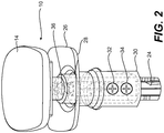
- Fig. 2 is a perspective illustration of the top end of the selector lever 10. As shown, the flared top 14 is disposed a distance from the pin release 26. In this orientation, the selector lever 10 is in a locked condition. The spring 36 is visible in this partially-skeletonized depiction of the top end of the selector lever 10. The fasteners 32, 34 also are visible in this view.
- Fig. 3 is a perspective illustration of a portion of the shaft 22 including the bottom end 38 of the movable shaft 24. The location of the pin 40 also is provided in this view.
- the pin 40 includes two projections 50, 52, which extend from either side of the shaft 22.
- the pin 40 also includes a flanged portion 54 on the side of the pin including the projection 52.
- the flange 54 helps to maintain the pin 40 in an appropriate position within the movable shaft 24.
- the shaft 22 includes two slots 56 on either side thereof. The projections 50, 52 extend outwardly from the movable shaft 24 through the slots 56.
- the design of aircraft parts relies frequently on the concept of redundancy. This concept is evident in the design of the pin 40 with its two projections 50, 52. With this in mind, the primary projection 50 cooperates with the secondary projection 52 to provide redundancy for the operation of the selector lever 10 within the housing 16. As will be made more apparent in the discussion that follows, if one of the projections 50, 52 were to break off of the movable shaft 24 or become damaged, the remaining projection would provide the locking function needed for operation of the selector lever 10.
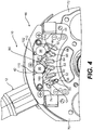
- Fig. 4 is a perspective illustration of a portion of the selector lever 10, showing a first embodiment of the detent plate 44 that forms a part of the present invention.
- the pin 40 and part of the movable shaft 24 are visible in this illustration.
- the selector lever 10 is in the locked condition, because the pin 40 engages one of the slots 42 in the detent plate 44.
- a second, redundant detent plate 44 which is disposed on the opposite side of the housing 16, parallel (or at least substantially parallel) to the first detent plate 44.
- the housing 16 incorporates two detent plates 44, which are identical to one another.
- One projection 50 engages with one of the detent plates 44 while the other projection 52 engages the other detent plate 44.
- each detent plate 44 incorporates 41, which define different positions for the flaps on the aircraft.
- each detent plate 44 includes six slots 42, which are labeled 58, 60, 62, 64, 66, 68.
- Each of the slots 42 are provided with a different identifying reference to facilitate the discussion that follows.
- the number and shape of the slots 58, 60, 62, 64, 66, 68 may be varied without departing from the scope of the present invention. In other words, a larger or a fewer number may be provided, depending upon the operational characteristics of the aircraft in which the selector lever 10 is installed.
- the housing 16 depicted in Fig. 4 is shown with a rear end 70 to the left and a front end 72 to the right.
- the definitions of "rear” and “front” are provided merely for reference and have no relationship to the longitudinal directions associated with the aircraft.
- the housing 16 is designed to have in inverted symmetry around a plane bisecting the housing 16 and extending parallel to the travel direction of the selector lever 10.
- the inverted symmetry will be described in greater detail below.
- the slot 58 is closest to the rear end 70 of the housing 16.
- the slot 68 is closest to the front end 72 of the housing 16.
- Each of the slots 58, 60, 62, 64, 66, 68 has a slightly different shape depending upon its location within the detent plate 44. As noted above, the shape of the slots 58, 60, 62, 64, 66, 68 need not be the same as those depicted to practice the present invention.
- the slot 58 includes a failure detection slot 74 near to an upper end thereof.
- the failure detection slot 74 is positioned so that the operator of the selector lever 10 may determine tactilely if one of the protrusions 50, 52 has broken off of the pin 40.
- the failure detection slot 74 is provided specifically to permit the operator, such as the pilot or co-pilot, to assess if there has been a dormant ( i.e., partial) failure of the pin 40.
- the failure detection may be performed automatically via a sensor that responds to an abnormal position of the selector lever 10.
- the failure detection slot 74 is intended to cooperate with the motion of the lever 12 when the lever 12 is at the position adjacent to the rear end 70 or adjacent to the front end 72 of the housing 16. Only one of the slots, specifically slot 58, incorporates the failure slot detent 74 therein. Because the housing has an inverted symmetry, the slot 58 on the right side of the housing 16 is adjacent to the rear end 70 of the housing 16 and the slot 58 on the left side of the housing 16 is adjacent to the front end 72 of the housing 16. In other words, the failure detection slot 74 is not at the same location on both sides of the housing 16.
- the inverted symmetry of the housing 16 is intentionally provided for the selector lever 10. The reason for this is simple. With an inverted symmetry, it is possible to determine if there is a failure of the pin 40 on either side of the lever 12. In other words, with an inverted symmetry, the pilot or co-pilot can determine that one of the protrusions 50, 52 is missing or damaged. This permits the replacement of the pin 40 before there is a total failure of the pin 40, which may result inadvertent deployment (or retraction) of the flaps and/or slats on the aircraft, unexpectedly affecting aircraft operation and performance.
- both of the protrusions 50, 52 are present on the pin 40 so that the pin 40 is operating as designed, the protrusions 50, 52 will engage the sides of the detents 41 and provide a "solid" feel to the engagement. In other words, when both protrusions 50, 52 are present and operating properly, the pilot will experience a solid engagement of the lever 12 at any of the positions for the slots 42 along the arc of the lever 12.
- the protrusion 52 when the lever 12 is in the rearmost position adjacent to the rear end 70 of the housing 16, when the pilot lifts up the pin release 26 and moves the pin 40 into the upper position, the protrusion 52 will be at the same level as the failure detection slot 74. If the protrusion 50 (on the opposite side of the lever 12) is missing, the lever 12 will be able to move forwardly and rearwardly within the failure detection slot 74. In other words, the absence of the protrusion 50 will permit the protrusion 52 to move within the failure detection slot 74. If the lever 12 moves when in this configuration, the protrusion 50 has become damaged or has failed, suggesting that the pin 40 should be replaced.
- a sensor may be connected to the lever 12 (or an associated structure) to measure if the lever 12 is in an abnormal position. If the sensor determines that the lever 12 is in an abnormal position, the sensor may provide a signal that triggers an alarm signaling that the protrusion 50 has become damaged or has failed.
- the lever 12 To test the viability of the protrusion 52, the lever 12 must be moved to the forwardmost position adjacent to the front end 72 of the housing 16.
- the slot 68 does not include a failure detection slot 74.
- the slot 58 on the other side of the housing 16 includes the failure detection slot 74, as illustrated. Accordingly, when the lever 12 is in the forwardmost position and the pin release 26 is actuated so that the lever 12 is in an unlocked condition, if the protrusion 52 is missing, the protrusion 50 will bottom inside of the failure detection slot 74. If the protrusion 52 is missing or damaged, the protrusion 50 will be able to move within the failure detection slot 74.
- the pilot is able to determine that the protrusion 52 is either damaged or missing and, therefore, that the pin 40 should be replaced. Again, one or more sensors may be employed to assist with this determination.
- the lever 12 may impact against the housing 16.
- the housing 16 includes a cutout 104 with a rearward edge 106 and a forward edge 108. If the protrusion 52 is missing from the pin 40, the protrusion 50 will bottom inside of the failure detection slot 74, permitting the lever 12 to strike the rearward edge 106 of the cutout 104. As should be apparent, if the protrusion 50 is missing, the lever 12 may strike the forward edge 108 of the cutout 104 in the housing 16.
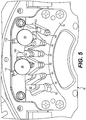
- Fig. 5 illustrates a second embodiment of the selector lever 10 of the present invention.
- the housing 16 includes a detent plate 76.
- the failure detection slot 78 is provided at the bottom portion (or trough) of the slot 58 instead of at the top end (or peak) of the slot 58.
- the failure detection slot 78 operates in the same manner as the slot 74 discussed above in connection with the embodiment illustrated in Figs. 1-4 .
- testing of the pin 40 occurs when the pin release 26 is in the locked position rather than in the unlocked position.
- the lever 12 may strike either edge 106, 108 of the cutout 104 in the top of the housing 16.
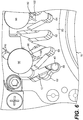
- Fig. 6 illustrates a partial view of a third embodiment of the detent plate 80 according to the present invention.
- the failure detection slot 82 is positioned at a midway point between the trough and the top of the slot 58.
- This embodiment recognizes that any position intermediate to the top and bottom of the slot 58 may be utilized for failure detection.
- Testing of the pin 40 occurs while the pin release 26 is in an intermediate position between the trough and the peak of the slot 58.
- a departure of the lever 12 from its normal position while the pin 40 is in transition between the top and bottom ends of the slot 58 would be indicative of a latent failure of the pin 40.
- the failure detection slot 84 may be located at any point between the trough and peak of the slot 58 without departing from the scope of the present invention.
- Fig. 7 is a partial view of a fourth embodiment of the detent plate 84 according to the present invention.
- the failure detection slot 86 is angled downwardly and rearward from the trough of the slot 58.
- the failure detection slot 86 has a configuration that differs from the configuration of the failure detection slot 74 illustrated in Fig. 5 .
- This embodiment also illustrates that the failure detection slot 86 need not follow a path that is parallel to the arched motion of the pin 40 when the lever 12 is moved between its rearwardmost position and its forwardmost position.
- the shape of the failure detection slot 86 may depart from the embodiments provided herein without departing from the scope of the present invention.
- the protrusion 52 is in a position where the protrusion 52 would be located if the protrusion 50 is not damaged or missing. If the protrusion 50 were damaged or missing, the protrusion 52 would move to the lowest position of the failure detection slot 86. Accordingly, the lever 12 would automatically travel to a non-standard position when the lever 12 is in the forwardmost or rearwardmost positions. This change in the position of the lever 12 would, therefore, indicate a partial failure of the pin 40, because the position of the lever 12 would differ from a normal positioning of the lever 12.
- Fig. 8 is a perspective illustration of a portion of the controller 10 that is common to all of the embodiments described for the present invention.
- Fig. 8 illustrates a gate mechanism 88 disposed near the top of the housing 16.
- Fig. 1 illustrates the contemplated position of the gate mechanism 88.
- the gate mechanism 88 includes a first gate 90 and a second gate 92.
- the first gate 90 is pivotally connected to a bridge 94 at the position of a first pin 96. As such, the first gate 90 pivots around the first pin 96.
- the second gate 92 is pivotally connected to the bridge 94 at the position of a second pin 98. Accordingly, the second gate 92 pivots around the second pin 98.
- a first spring 100 extends around the first pin 96 and abuts against a first spring pin 110 at one end the first gate 90 at the other end to maintain the first gate 90 in a closed, blocking position.
- a second spring 102 extends around the second pin 98 and abuts against a second spring pin 112 at one end and the second gate 92 at the other end to maintain the second gate 92 in a closed, blocking position.
- the first and second gates 90, 92 act as a ratchet to arrest the movement of the lever 12 in one direction, as required by regulations.
- the gates 90, 92 allow unrestricted movement of the lever 12 in the opposite direction.
- Fig. 9 is a side view of one of the detent plates 76 that are illustrated in Fig. 5 .
- the detent plate 76 is in the same orientation of as the detent plate 76 illustrated in Fig. 5 .
- the protrusion 52 of the pin 40 is shown in the position where the protrusion 52 would be located during non-failure operation. As noted above, if there has been a failure of the protrusion 50, the protrusion 52 engages the failure detection slot 78, permitting detection of the latent defect.
- Fig. 10 is a perspective illustration of the detent plate 76 illustrated in Fig. 9 from the opposite side.
- the pin 40, together with its protrusions 50, 52, is visible in this view.
- the failure detection slot 74, 78, 82. 86 may be incorporated into any one of the slots 58, 60, 62, 64, 66, 68 without departing from the scope of the present invention.
- the present invention should not be understood to be limited to one embodiment where the failure detection slot 74, 78, 82. 86 is included only in the slot 58.
- a cover of the housing 16 may be designed to include indicia to illustrate when the lever 12 has exceeded a normal position.
- a sensor may be provided on the cross-shaft 20.
- the sensor would be configured to detect if the lever 12 moves outside of a normal range of operation by detecting, for example, the angular position of the shaft 24.
- the sensor would detect a change in the angular position of the lever 12.
- the sensor may be connected to an alarm to provide an audible or a visual indication of the potential failure of one of the protrusions 50, 52.
- the senor 114 may be positioned on (or in association with) the cross-shaft 20.
- the sensor 114 may transmit a signal to a processor 116 connected thereto.
- the processor 116 after receiving a signal indicative of a deviation of the lever 12 from a normal position, may then issue an alarm signal to one or more alarm devices, including a speaker 118 that issues an audible alert.
- sensors may be provided in the failure detection slots 74, 78, 82, 86 themselves.
- the sensor may be configured to generate a signal that would trigger a suitable alarm.
- the present invention is described in connection with one or more embodiments thereof.
- the embodiments are intended to be illustrative of the breadth of the present invention. Focus on any one particular embodiment is not intended to be limiting thereof.
Landscapes
- Engineering & Computer Science (AREA)
- Aviation & Aerospace Engineering (AREA)
- Automation & Control Theory (AREA)
- Physics & Mathematics (AREA)
- General Physics & Mathematics (AREA)
- Mechanical Control Devices (AREA)
- Transmission Devices (AREA)
- Train Traffic Observation, Control, And Security (AREA)
Claims (15)
- Wählhebel (10), umfassend:ein Gehäuse (16), das einen vorderen und einen hinteren Teil definiert;einen Hebel (12) mit einer im Gehäuse auf einer Querwelle (20) zentral angeordneten Welle (22), wobei die Welle eine Wellenachse definiert und wobei der Hebel (12) ein oberes Ende aufweist, das außerhalb des Gehäuses (16) angeordnet ist;eine bewegliche Welle (24), die mit dem Hebel (12) verbunden ist, wobei die bewegliche Welle im Wesentlichen axial entlang der Wellenachse beweglich ist;ein Stift (40) der zum unteren Ende (38) der beweglichen Welle (24) benachbart angeordnet ist, wobei der Stift (40) einen ersten Vorsprung (50) axial gegenüber einem zweiten Vorsprung (52) umfasst;eine erste Rastplatte (44), die auf einer ersten Seite der beweglichen Welle (24) angeordnet ist, wobei die erste Rastplatte (44) mindestens einen ersten Schlitz (58) zur Aufnahme des ersten Vorsprungs (50) darin aufweist;dadurch gekennzeichnet, dass der Wählhebel ferner eine zweite Rastplatte (44) umfasst, die auf einer zweiten Seite der beweglichen Welle (24) im Wesentlichen parallel zur ersten Rastplatte (44) angeordnet ist, wobei die zweite Rastplatte (44) mindestens einen zweiten Schlitz (42) zur Aufnahme des zweiten Vorsprungs (52) aufweist; undeinen ersten Fehlererkennungsschlitz (74) innerhalb der ersten Rastplatte (44) zur Aufnahme des ersten Vorsprungs (50),wobei die zweite Rastplatte (44) die Bewegung des ersten Vorsprungs (50) innerhalb des ersten Fehlererkennungsschlitzes (74) verhindert, es sei denn der zweite Vorsprung (52) fehlt oder ist beschädigt.
- Wählhebel nach Anspruch 1, ferner umfassend eines oder mehrere der folgenden:ein Vorspannungselement (36), das operativ zwischen der Welle und der beweglichen Welle angeordnet ist, um die bewegliche Welle zur Querwelle vorzuspannen;einen zweiten Fehlererkennungsschlitz (78) innerhalb der zweiten Rastplatte zur Aufnahme des zweiten Vorsprungs (52),wobei die erste Rastplatte die Bewegung des zweiten Vorsprungs (52) innerhalb des zweiten Fehlererkennungsschlitzes (78) verhindert, wenn der erste Vorsprung (50) fehlt;einen Stift-Auslösemechanismus (26), der mit der beweglichen Welle zur Manipulation der beweglichen Welle (24) verbunden ist, so dass der Hebel aus einer verriegelten in eine entriegelte Position übergehen kann.
- Wählhebel nach Anspruch 2 wobei der Stift-Auslösemechanismus Folgendes umfasst:eine Hülle, die die bewegliche Welle mindestens teilweise umschließt und mit ihr verbunden ist; und ein oberes Ende in T-Form.
- Wählhebel nach Anspruch 2 wobei das Vorspannungselement eine Feder ist.
- Wählhebel nach Anspruch 4 wobei die Feder eine Schraubenfeder ist.
- Wählhebel nach einem der vorhergehenden Ansprüche, ferner beinhaltend eines oder mehrere der folgenden:wobei die erste Rastplatte eine Vielzahl von Schlitzen beinhaltet;wobei der obere Bereich des Hebels durch Zusammendrücken von Hand mit dem Stift-Auslösemechanismus kooperiert;wobei die zweite Rastplatte eine Vielzahl von Schlitzen beinhaltet.
- Wählhebel nach einem der vorhergehenden Ansprüche, wobei der erste Fehlererkennungsschlitz benachbart zu einer Mulde des ersten Schlitzes angeordnet ist.
- Wählhebel nach einem der vorhergehenden Ansprüche, wobei der erste Fehlererkennungsschlitz benachbart zu einer Spitze des ersten Schlitzes angeordnet ist.
- Wählhebel nach einem der Ansprüche 2 bis 8, wobei der zweite Fehlererkennungsschlitz benachbart zu einer Mulde des zweiten Schlitzes angeordnet ist.
- Wählhebel nach einem der Ansprüche 2 bis 9, wobei der zweite Fehlererkennungsschlitz benachbart zu einer Spitze des zweiten Schlitzes angeordnet ist.
- Wählhebel nach einem der vorhergehenden Ansprüche, ferner beinhaltend eines oder mehrere der folgenden:wobei der erste Schlitz benachbart zum hinteren Teil des Gehäuses angeordnet ist; undwobei der zweite Schlitz benachbart zum hinteren Teil des Gehäuses oder zum vorderen Teil des Gehäuses angeordnet ist.
- Wählhebel nach einem der vorhergehenden Ansprüche, ferner beinhaltend eines oder mehrere der folgenden:wobei der erste Schlitz benachbart zum vorderen Teil des Gehäuses angeordnet ist; undwobei der zweite Schlitz benachbart zum vorderen Teil des Gehäuses angeordnet ist.
- Wählhebel nach einem der vorhergehenden Ansprüche, wobei die erste Rastplatte und die zweite Rastplatte eine umgekehrte Symmetrie zueinander aufweisen.
- Wählhebel nach einem der vorhergehenden Ansprüche, wobei der Wählhebel die Steuerung für mindestens eines von Landeklappen und Vorflügeln an einem Flugzeug bereitstellt.
- Wählhebel nach einem der vorhergehenden Ansprüche, ferner umfassend:einen Sensor zur Erkennung einer Position des Hebels, die von einer voreingestellten Position abweicht.
Applications Claiming Priority (1)
| Application Number | Priority Date | Filing Date | Title |
|---|---|---|---|
| PCT/US2012/066620 WO2014084809A1 (en) | 2012-11-27 | 2012-11-27 | Failure detection mechanism for selector lever |
Publications (2)
| Publication Number | Publication Date |
|---|---|
| EP2925603A1 EP2925603A1 (de) | 2015-10-07 |
| EP2925603B1 true EP2925603B1 (de) | 2017-09-13 |
Family
ID=47425291
Family Applications (1)
| Application Number | Title | Priority Date | Filing Date |
|---|---|---|---|
| EP12805493.9A Active EP2925603B1 (de) | 2012-11-27 | 2012-11-27 | Fehlererkennungsmechanismus für wählhebel |
Country Status (5)
| Country | Link |
|---|---|
| US (1) | US9643715B2 (de) |
| EP (1) | EP2925603B1 (de) |
| CN (1) | CN104812667B (de) |
| CA (1) | CA2891329C (de) |
| WO (1) | WO2014084809A1 (de) |
Families Citing this family (16)
| Publication number | Priority date | Publication date | Assignee | Title |
|---|---|---|---|---|
| US10031546B2 (en) | 2014-09-24 | 2018-07-24 | Hamilton Sundstrand Corporation | Visual failure indication for selector lever |
| US9517835B2 (en) | 2014-09-24 | 2016-12-13 | Hamilton Sundstrand Corporation | Device for preventing rotational movement of failed selector lever |
| US20160085258A1 (en) * | 2014-09-24 | 2016-03-24 | Hamilton Sundstrand Corporation | Selector lever with failure indication features |
| US9771143B2 (en) | 2014-09-24 | 2017-09-26 | Hamilton Sundstrand Corporation | Selector lever with independent slides |
| CN105424358B (zh) * | 2015-11-25 | 2018-10-16 | 燕山大学 | 试验台选换挡位移测试装置及方法 |
| US10372149B2 (en) * | 2016-07-13 | 2019-08-06 | Hamilton Sundstrand Corporation | Detent alignment mechanism assembly |
| CN106292834A (zh) * | 2016-10-31 | 2017-01-04 | 苏州市淞舜五金有限公司 | 一种磁性限位控制杆组件 |
| CN106325355B (zh) * | 2016-10-31 | 2018-01-05 | 苏州中拓专利运营管理有限公司 | 一种磁性控制杆组件 |
| CN106325357A (zh) * | 2016-10-31 | 2017-01-11 | 苏州市淞舜五金有限公司 | 一种带限位的旋拧控制杆组件 |
| CN106325356A (zh) * | 2016-10-31 | 2017-01-11 | 苏州市淞舜五金有限公司 | 一种旋拧控制杆组件 |
| CN106292833A (zh) * | 2016-10-31 | 2017-01-04 | 苏州市淞舜五金有限公司 | 一种端部限位控制杆组件 |
| US10351257B2 (en) | 2017-09-28 | 2019-07-16 | Hamilton Sundstrand Corporation | Retention member monitoring system for slat-flap control lever |
| US10870482B2 (en) * | 2018-04-13 | 2020-12-22 | Hamilton Sunstrand Corporation | Aircraft control selector levers |
| CN109250150B (zh) * | 2018-09-25 | 2022-04-19 | 陕西飞机工业(集团)有限公司 | 一种飞机扰流板仿真控制器 |
| CN110979639B (zh) * | 2019-12-20 | 2021-11-19 | 中国商用飞机有限责任公司 | 飞机的襟/缝翼手柄装置 |
| JP7460142B2 (ja) | 2020-07-20 | 2024-04-02 | 多摩川精機株式会社 | レバー装置用ディテント機構及びそのディテント方法 |
Family Cites Families (13)
| Publication number | Priority date | Publication date | Assignee | Title |
|---|---|---|---|---|
| US1987066A (en) * | 1933-01-30 | 1935-01-08 | Gen Aviat Mfg Corp | Vernier adjusting control unit |
| US2506222A (en) * | 1946-04-18 | 1950-05-02 | Kesses Charles | Controlling stick for airplanes |
| GB747507A (en) * | 1953-09-15 | 1956-04-04 | Northrop Aircraft Inc | Improvements in control systems for actuating the control surfaces of an airplane, particularly control systems for conjointly operating the airplane ailerons and landing flaps |
| US3710644A (en) | 1971-07-29 | 1973-01-16 | Mc Donnell Douglas Corp | Control setting apparatus |
| US3935754A (en) | 1974-06-14 | 1976-02-03 | The Boeing Company | Failure detector and indicator for aircraft flap actuation system |
| US4154415A (en) * | 1977-12-30 | 1979-05-15 | The United States Of America As Represented By The Secretary Of The Air Force | Modulating vernier flap control system |
| US4244541A (en) | 1979-01-02 | 1981-01-13 | The Boeing Company | Dual cam control mechanism for coordinated deployment and retraction of an air-craft's leading and trailing edge wing flaps |
| DE4029330A1 (de) * | 1990-09-15 | 1992-03-26 | Porsche Ag | Schaltvorrichtung fuer ein kraftfahrzeuggetriebe |
| DE19633948A1 (de) * | 1996-08-22 | 1998-02-26 | Bayerische Motoren Werke Ag | Wähleinrichtung für ein Automatikgetriebe eines Kraftfahrzeugs |
| JP2000043601A (ja) * | 1998-07-30 | 2000-02-15 | Tokai Rika Co Ltd | シフトレバー装置 |
| DE10249967B4 (de) | 2002-10-26 | 2006-03-09 | Airbus Deutschland Gmbh | Vorrichtung zur Ansteuerung der Vorflügel und Landeklappen eines Flugzeuges |
| JP5309138B2 (ja) * | 2007-08-08 | 2013-10-09 | ムーグ インコーポレーテッド | フライバイワイヤ飛行制御システムでの使用に適合した操縦桿及びそれに使用する連結機構 |
| FR2952448B1 (fr) * | 2009-11-06 | 2012-08-03 | Ratier Figeac Soc | Dispositif de controle electronique d'un organe de pilotage a microcontroleurs multifonctionnels, dispositif de pilotage et aeronef |
-
2012
- 2012-11-27 EP EP12805493.9A patent/EP2925603B1/de active Active
- 2012-11-27 WO PCT/US2012/066620 patent/WO2014084809A1/en not_active Ceased
- 2012-11-27 CA CA2891329A patent/CA2891329C/en active Active
- 2012-11-27 CN CN201280077278.8A patent/CN104812667B/zh active Active
- 2012-11-27 US US14/441,432 patent/US9643715B2/en active Active
Non-Patent Citations (1)
| Title |
|---|
| None * |
Also Published As
| Publication number | Publication date |
|---|---|
| CN104812667B (zh) | 2017-05-31 |
| CA2891329A1 (en) | 2014-06-05 |
| CA2891329C (en) | 2019-03-12 |
| EP2925603A1 (de) | 2015-10-07 |
| CN104812667A (zh) | 2015-07-29 |
| US20150266564A1 (en) | 2015-09-24 |
| WO2014084809A1 (en) | 2014-06-05 |
| US9643715B2 (en) | 2017-05-09 |
Similar Documents
| Publication | Publication Date | Title |
|---|---|---|
| EP2925603B1 (de) | Fehlererkennungsmechanismus für wählhebel | |
| US6913226B2 (en) | Methods and systems for redundant control and/or failure detection | |
| EP0726201B1 (de) | Kabel zur Ueberwachung des Schiefstandes von benachbarten Tragflächen | |
| CA2976094C (en) | Secondary load path detection | |
| JP5989323B2 (ja) | プッシュ・プル相互連接ロッドを有するライン交換可能なフライ・バイ・ワイヤ方式のコントロール・カラム | |
| EP3863924B1 (de) | Sicherungsmechanismus für fahrwerkssystem | |
| US8123177B2 (en) | Input system for a landing flap control of an aircraft | |
| EP3153405B1 (de) | Visuelle fehleranzeige für wählhebel | |
| US10087663B2 (en) | Monitoring system for monitoring a two-part-cowl lock unit | |
| CA2885135C (en) | Systems and methods for operating flight control surfaces | |
| CN112351937A (zh) | 控制面元件倾斜和/或损失检测系统 | |
| EP3403920B1 (de) | Flugzeugtürsteuerung | |
| RU2016113677A (ru) | Механизм контроля за устройством обнаружения неисправности первичной передачи нагрузки исполнительному приводу управления летательным аппаратом | |
| US9517835B2 (en) | Device for preventing rotational movement of failed selector lever | |
| US5820071A (en) | Mechanical coupler/decoupler | |
| US11708178B2 (en) | Monitoring system for an assembly having a kinematic coupling | |
| BRPI1104033B1 (pt) | controlador de roda para uma aeronave e aeronave | |
| US12510140B2 (en) | Trimmable horizontal stabiliser actuator secondary load path detector | |
| US9928972B1 (en) | Limit switch housing with reset function | |
| KR200469948Y1 (ko) | 엔진추력조절장치 | |
| EP4382413B1 (de) | Untere befestigung für einen aktuator eines trimmbaren höhenleitwerks |
Legal Events
| Date | Code | Title | Description |
|---|---|---|---|
| PUAI | Public reference made under article 153(3) epc to a published international application that has entered the european phase |
Free format text: ORIGINAL CODE: 0009012 |
|
| 17P | Request for examination filed |
Effective date: 20150603 |
|
| AK | Designated contracting states |
Kind code of ref document: A1 Designated state(s): AL AT BE BG CH CY CZ DE DK EE ES FI FR GB GR HR HU IE IS IT LI LT LU LV MC MK MT NL NO PL PT RO RS SE SI SK SM TR |
|
| AX | Request for extension of the european patent |
Extension state: BA ME |
|
| DAX | Request for extension of the european patent (deleted) | ||
| GRAP | Despatch of communication of intention to grant a patent |
Free format text: ORIGINAL CODE: EPIDOSNIGR1 |
|
| INTG | Intention to grant announced |
Effective date: 20160524 |
|
| GRAJ | Information related to disapproval of communication of intention to grant by the applicant or resumption of examination proceedings by the epo deleted |
Free format text: ORIGINAL CODE: EPIDOSDIGR1 |
|
| INTC | Intention to grant announced (deleted) | ||
| 17Q | First examination report despatched |
Effective date: 20161115 |
|
| GRAP | Despatch of communication of intention to grant a patent |
Free format text: ORIGINAL CODE: EPIDOSNIGR1 |
|
| INTG | Intention to grant announced |
Effective date: 20170424 |
|
| GRAS | Grant fee paid |
Free format text: ORIGINAL CODE: EPIDOSNIGR3 |
|
| GRAA | (expected) grant |
Free format text: ORIGINAL CODE: 0009210 |
|
| AK | Designated contracting states |
Kind code of ref document: B1 Designated state(s): AL AT BE BG CH CY CZ DE DK EE ES FI FR GB GR HR HU IE IS IT LI LT LU LV MC MK MT NL NO PL PT RO RS SE SI SK SM TR |
|
| REG | Reference to a national code |
Ref country code: GB Ref legal event code: FG4D |
|
| REG | Reference to a national code |
Ref country code: CH Ref legal event code: EP |
|
| REG | Reference to a national code |
Ref country code: IE Ref legal event code: FG4D |
|
| REG | Reference to a national code |
Ref country code: AT Ref legal event code: REF Ref document number: 927849 Country of ref document: AT Kind code of ref document: T Effective date: 20171015 |
|
| REG | Reference to a national code |
Ref country code: DE Ref legal event code: R096 Ref document number: 602012037376 Country of ref document: DE |
|
| REG | Reference to a national code |
Ref country code: FR Ref legal event code: PLFP Year of fee payment: 6 |
|
| REG | Reference to a national code |
Ref country code: NL Ref legal event code: MP Effective date: 20170913 |
|
| REG | Reference to a national code |
Ref country code: LT Ref legal event code: MG4D |
|
| PG25 | Lapsed in a contracting state [announced via postgrant information from national office to epo] |
Ref country code: NO Free format text: LAPSE BECAUSE OF FAILURE TO SUBMIT A TRANSLATION OF THE DESCRIPTION OR TO PAY THE FEE WITHIN THE PRESCRIBED TIME-LIMIT Effective date: 20171213 Ref country code: FI Free format text: LAPSE BECAUSE OF FAILURE TO SUBMIT A TRANSLATION OF THE DESCRIPTION OR TO PAY THE FEE WITHIN THE PRESCRIBED TIME-LIMIT Effective date: 20170913 Ref country code: LT Free format text: LAPSE BECAUSE OF FAILURE TO SUBMIT A TRANSLATION OF THE DESCRIPTION OR TO PAY THE FEE WITHIN THE PRESCRIBED TIME-LIMIT Effective date: 20170913 Ref country code: HR Free format text: LAPSE BECAUSE OF FAILURE TO SUBMIT A TRANSLATION OF THE DESCRIPTION OR TO PAY THE FEE WITHIN THE PRESCRIBED TIME-LIMIT Effective date: 20170913 Ref country code: SE Free format text: LAPSE BECAUSE OF FAILURE TO SUBMIT A TRANSLATION OF THE DESCRIPTION OR TO PAY THE FEE WITHIN THE PRESCRIBED TIME-LIMIT Effective date: 20170913 |
|
| REG | Reference to a national code |
Ref country code: AT Ref legal event code: MK05 Ref document number: 927849 Country of ref document: AT Kind code of ref document: T Effective date: 20170913 |
|
| PG25 | Lapsed in a contracting state [announced via postgrant information from national office to epo] |
Ref country code: LV Free format text: LAPSE BECAUSE OF FAILURE TO SUBMIT A TRANSLATION OF THE DESCRIPTION OR TO PAY THE FEE WITHIN THE PRESCRIBED TIME-LIMIT Effective date: 20170913 Ref country code: GR Free format text: LAPSE BECAUSE OF FAILURE TO SUBMIT A TRANSLATION OF THE DESCRIPTION OR TO PAY THE FEE WITHIN THE PRESCRIBED TIME-LIMIT Effective date: 20171214 Ref country code: RS Free format text: LAPSE BECAUSE OF FAILURE TO SUBMIT A TRANSLATION OF THE DESCRIPTION OR TO PAY THE FEE WITHIN THE PRESCRIBED TIME-LIMIT Effective date: 20170913 Ref country code: ES Free format text: LAPSE BECAUSE OF FAILURE TO SUBMIT A TRANSLATION OF THE DESCRIPTION OR TO PAY THE FEE WITHIN THE PRESCRIBED TIME-LIMIT Effective date: 20170913 Ref country code: BG Free format text: LAPSE BECAUSE OF FAILURE TO SUBMIT A TRANSLATION OF THE DESCRIPTION OR TO PAY THE FEE WITHIN THE PRESCRIBED TIME-LIMIT Effective date: 20171213 |
|
| PG25 | Lapsed in a contracting state [announced via postgrant information from national office to epo] |
Ref country code: NL Free format text: LAPSE BECAUSE OF FAILURE TO SUBMIT A TRANSLATION OF THE DESCRIPTION OR TO PAY THE FEE WITHIN THE PRESCRIBED TIME-LIMIT Effective date: 20170913 |
|
| PG25 | Lapsed in a contracting state [announced via postgrant information from national office to epo] |
Ref country code: RO Free format text: LAPSE BECAUSE OF FAILURE TO SUBMIT A TRANSLATION OF THE DESCRIPTION OR TO PAY THE FEE WITHIN THE PRESCRIBED TIME-LIMIT Effective date: 20170913 Ref country code: CZ Free format text: LAPSE BECAUSE OF FAILURE TO SUBMIT A TRANSLATION OF THE DESCRIPTION OR TO PAY THE FEE WITHIN THE PRESCRIBED TIME-LIMIT Effective date: 20170913 Ref country code: PL Free format text: LAPSE BECAUSE OF FAILURE TO SUBMIT A TRANSLATION OF THE DESCRIPTION OR TO PAY THE FEE WITHIN THE PRESCRIBED TIME-LIMIT Effective date: 20170913 |
|
| PG25 | Lapsed in a contracting state [announced via postgrant information from national office to epo] |
Ref country code: EE Free format text: LAPSE BECAUSE OF FAILURE TO SUBMIT A TRANSLATION OF THE DESCRIPTION OR TO PAY THE FEE WITHIN THE PRESCRIBED TIME-LIMIT Effective date: 20170913 Ref country code: SK Free format text: LAPSE BECAUSE OF FAILURE TO SUBMIT A TRANSLATION OF THE DESCRIPTION OR TO PAY THE FEE WITHIN THE PRESCRIBED TIME-LIMIT Effective date: 20170913 Ref country code: AT Free format text: LAPSE BECAUSE OF FAILURE TO SUBMIT A TRANSLATION OF THE DESCRIPTION OR TO PAY THE FEE WITHIN THE PRESCRIBED TIME-LIMIT Effective date: 20170913 Ref country code: SM Free format text: LAPSE BECAUSE OF FAILURE TO SUBMIT A TRANSLATION OF THE DESCRIPTION OR TO PAY THE FEE WITHIN THE PRESCRIBED TIME-LIMIT Effective date: 20170913 Ref country code: IS Free format text: LAPSE BECAUSE OF FAILURE TO SUBMIT A TRANSLATION OF THE DESCRIPTION OR TO PAY THE FEE WITHIN THE PRESCRIBED TIME-LIMIT Effective date: 20180113 Ref country code: IT Free format text: LAPSE BECAUSE OF FAILURE TO SUBMIT A TRANSLATION OF THE DESCRIPTION OR TO PAY THE FEE WITHIN THE PRESCRIBED TIME-LIMIT Effective date: 20170913 |
|
| REG | Reference to a national code |
Ref country code: DE Ref legal event code: R097 Ref document number: 602012037376 Country of ref document: DE |
|
| PG25 | Lapsed in a contracting state [announced via postgrant information from national office to epo] |
Ref country code: MC Free format text: LAPSE BECAUSE OF FAILURE TO SUBMIT A TRANSLATION OF THE DESCRIPTION OR TO PAY THE FEE WITHIN THE PRESCRIBED TIME-LIMIT Effective date: 20170913 |
|
| PLBE | No opposition filed within time limit |
Free format text: ORIGINAL CODE: 0009261 |
|
| STAA | Information on the status of an ep patent application or granted ep patent |
Free format text: STATUS: NO OPPOSITION FILED WITHIN TIME LIMIT |
|
| PG25 | Lapsed in a contracting state [announced via postgrant information from national office to epo] |
Ref country code: LI Free format text: LAPSE BECAUSE OF NON-PAYMENT OF DUE FEES Effective date: 20171130 Ref country code: CH Free format text: LAPSE BECAUSE OF NON-PAYMENT OF DUE FEES Effective date: 20171130 Ref country code: DK Free format text: LAPSE BECAUSE OF FAILURE TO SUBMIT A TRANSLATION OF THE DESCRIPTION OR TO PAY THE FEE WITHIN THE PRESCRIBED TIME-LIMIT Effective date: 20170913 |
|
| 26N | No opposition filed |
Effective date: 20180614 |
|
| PG25 | Lapsed in a contracting state [announced via postgrant information from national office to epo] |
Ref country code: LU Free format text: LAPSE BECAUSE OF NON-PAYMENT OF DUE FEES Effective date: 20171127 |
|
| REG | Reference to a national code |
Ref country code: BE Ref legal event code: MM Effective date: 20171130 |
|
| REG | Reference to a national code |
Ref country code: IE Ref legal event code: MM4A |
|
| PG25 | Lapsed in a contracting state [announced via postgrant information from national office to epo] |
Ref country code: MT Free format text: LAPSE BECAUSE OF NON-PAYMENT OF DUE FEES Effective date: 20171127 |
|
| PG25 | Lapsed in a contracting state [announced via postgrant information from national office to epo] |
Ref country code: IE Free format text: LAPSE BECAUSE OF NON-PAYMENT OF DUE FEES Effective date: 20171127 |
|
| PG25 | Lapsed in a contracting state [announced via postgrant information from national office to epo] |
Ref country code: SI Free format text: LAPSE BECAUSE OF FAILURE TO SUBMIT A TRANSLATION OF THE DESCRIPTION OR TO PAY THE FEE WITHIN THE PRESCRIBED TIME-LIMIT Effective date: 20170913 Ref country code: BE Free format text: LAPSE BECAUSE OF NON-PAYMENT OF DUE FEES Effective date: 20171130 |
|
| PG25 | Lapsed in a contracting state [announced via postgrant information from national office to epo] |
Ref country code: HU Free format text: LAPSE BECAUSE OF FAILURE TO SUBMIT A TRANSLATION OF THE DESCRIPTION OR TO PAY THE FEE WITHIN THE PRESCRIBED TIME-LIMIT; INVALID AB INITIO Effective date: 20121127 |
|
| PG25 | Lapsed in a contracting state [announced via postgrant information from national office to epo] |
Ref country code: CY Free format text: LAPSE BECAUSE OF FAILURE TO SUBMIT A TRANSLATION OF THE DESCRIPTION OR TO PAY THE FEE WITHIN THE PRESCRIBED TIME-LIMIT Effective date: 20170913 |
|
| PG25 | Lapsed in a contracting state [announced via postgrant information from national office to epo] |
Ref country code: MK Free format text: LAPSE BECAUSE OF FAILURE TO SUBMIT A TRANSLATION OF THE DESCRIPTION OR TO PAY THE FEE WITHIN THE PRESCRIBED TIME-LIMIT Effective date: 20170913 |
|
| PG25 | Lapsed in a contracting state [announced via postgrant information from national office to epo] |
Ref country code: TR Free format text: LAPSE BECAUSE OF FAILURE TO SUBMIT A TRANSLATION OF THE DESCRIPTION OR TO PAY THE FEE WITHIN THE PRESCRIBED TIME-LIMIT Effective date: 20170913 |
|
| PG25 | Lapsed in a contracting state [announced via postgrant information from national office to epo] |
Ref country code: PT Free format text: LAPSE BECAUSE OF FAILURE TO SUBMIT A TRANSLATION OF THE DESCRIPTION OR TO PAY THE FEE WITHIN THE PRESCRIBED TIME-LIMIT Effective date: 20170913 |
|
| PG25 | Lapsed in a contracting state [announced via postgrant information from national office to epo] |
Ref country code: AL Free format text: LAPSE BECAUSE OF FAILURE TO SUBMIT A TRANSLATION OF THE DESCRIPTION OR TO PAY THE FEE WITHIN THE PRESCRIBED TIME-LIMIT Effective date: 20170913 |
|
| REG | Reference to a national code |
Ref country code: DE Ref legal event code: R082 Ref document number: 602012037376 Country of ref document: DE Representative=s name: HERNANDEZ, YORCK, DIPL.-ING., DE Ref country code: DE Ref legal event code: R081 Ref document number: 602012037376 Country of ref document: DE Owner name: BOMBARDIER INC., MONTREAL, CA Free format text: FORMER OWNER: BOMBARDIER INC., DORVAL, QUEBEC, CA Ref country code: DE Ref legal event code: R081 Ref document number: 602012037376 Country of ref document: DE Owner name: C SERIES AIRCRAFT LIMITED PARTNERSHIP, MIRABEL, CA Free format text: FORMER OWNER: BOMBARDIER INC., DORVAL, QUEBEC, CA Ref country code: DE Ref legal event code: R081 Ref document number: 602012037376 Country of ref document: DE Owner name: AIRBUS CANADA LIMITED PARTNERSHIP, MIRABEL, CA Free format text: FORMER OWNER: BOMBARDIER INC., DORVAL, QUEBEC, CA |
|
| REG | Reference to a national code |
Ref country code: GB Ref legal event code: 732E Free format text: REGISTERED BETWEEN 20200903 AND 20200910 |
|
| REG | Reference to a national code |
Ref country code: DE Ref legal event code: R082 Ref document number: 602012037376 Country of ref document: DE Representative=s name: HERNANDEZ, YORCK, DIPL.-ING., DE Ref country code: DE Ref legal event code: R081 Ref document number: 602012037376 Country of ref document: DE Owner name: AIRBUS CANADA LIMITED PARTNERSHIP, MIRABEL, CA Free format text: FORMER OWNERS: BOMBARDIER INC., MONTREAL, QUEBEC, CA; C SERIES AIRCRAFT LIMITED PARTNERSHIP, MIRABEL, QC, CA Ref country code: DE Ref legal event code: R081 Ref document number: 602012037376 Country of ref document: DE Owner name: BOMBARDIER INC., MONTREAL, CA Free format text: FORMER OWNERS: BOMBARDIER INC., MONTREAL, QUEBEC, CA; C SERIES AIRCRAFT LIMITED PARTNERSHIP, MIRABEL, QC, CA |
|
| P01 | Opt-out of the competence of the unified patent court (upc) registered |
Effective date: 20230529 |
|
| PGFP | Annual fee paid to national office [announced via postgrant information from national office to epo] |
Ref country code: DE Payment date: 20251119 Year of fee payment: 14 |
|
| PGFP | Annual fee paid to national office [announced via postgrant information from national office to epo] |
Ref country code: GB Payment date: 20251121 Year of fee payment: 14 |
|
| PGFP | Annual fee paid to national office [announced via postgrant information from national office to epo] |
Ref country code: FR Payment date: 20251125 Year of fee payment: 14 |