EP2925974B1 - Gasturbine mit einem schmiersystem sowie verfahren - Google Patents
Gasturbine mit einem schmiersystem sowie verfahren Download PDFInfo
- Publication number
- EP2925974B1 EP2925974B1 EP13858861.1A EP13858861A EP2925974B1 EP 2925974 B1 EP2925974 B1 EP 2925974B1 EP 13858861 A EP13858861 A EP 13858861A EP 2925974 B1 EP2925974 B1 EP 2925974B1
- Authority
- EP
- European Patent Office
- Prior art keywords
- engine
- lubricant
- gas turbine
- conduit
- flow
- Prior art date
- Legal status (The legal status is an assumption and is not a legal conclusion. Google has not performed a legal analysis and makes no representation as to the accuracy of the status listed.)
- Active
Links
Images


Classifications
-
- F—MECHANICAL ENGINEERING; LIGHTING; HEATING; WEAPONS; BLASTING
- F02—COMBUSTION ENGINES; HOT-GAS OR COMBUSTION-PRODUCT ENGINE PLANTS
- F02C—GAS-TURBINE PLANTS; AIR INTAKES FOR JET-PROPULSION PLANTS; CONTROLLING FUEL SUPPLY IN AIR-BREATHING JET-PROPULSION PLANTS
- F02C7/00—Features, components parts, details or accessories, not provided for in, or of interest apart form groups F02C1/00 - F02C6/00; Air intakes for jet-propulsion plants
- F02C7/06—Arrangements of bearings; Lubricating
-
- F—MECHANICAL ENGINEERING; LIGHTING; HEATING; WEAPONS; BLASTING
- F01—MACHINES OR ENGINES IN GENERAL; ENGINE PLANTS IN GENERAL; STEAM ENGINES
- F01D—NON-POSITIVE DISPLACEMENT MACHINES OR ENGINES, e.g. STEAM TURBINES
- F01D25/00—Component parts, details, or accessories, not provided for in, or of interest apart from, other groups
- F01D25/18—Lubricating arrangements
- F01D25/20—Lubricating arrangements using lubrication pumps
-
- F—MECHANICAL ENGINEERING; LIGHTING; HEATING; WEAPONS; BLASTING
- F05—INDEXING SCHEMES RELATING TO ENGINES OR PUMPS IN VARIOUS SUBCLASSES OF CLASSES F01-F04
- F05D—INDEXING SCHEME FOR ASPECTS RELATING TO NON-POSITIVE-DISPLACEMENT MACHINES OR ENGINES, GAS-TURBINES OR JET-PROPULSION PLANTS
- F05D2270/00—Control
- F05D2270/30—Control parameters, e.g. input parameters
- F05D2270/301—Pressure
-
- F—MECHANICAL ENGINEERING; LIGHTING; HEATING; WEAPONS; BLASTING
- F05—INDEXING SCHEMES RELATING TO ENGINES OR PUMPS IN VARIOUS SUBCLASSES OF CLASSES F01-F04
- F05D—INDEXING SCHEME FOR ASPECTS RELATING TO NON-POSITIVE-DISPLACEMENT MACHINES OR ENGINES, GAS-TURBINES OR JET-PROPULSION PLANTS
- F05D2270/00—Control
- F05D2270/30—Control parameters, e.g. input parameters
- F05D2270/304—Spool rotational speed
-
- F—MECHANICAL ENGINEERING; LIGHTING; HEATING; WEAPONS; BLASTING
- F05—INDEXING SCHEMES RELATING TO ENGINES OR PUMPS IN VARIOUS SUBCLASSES OF CLASSES F01-F04
- F05D—INDEXING SCHEME FOR ASPECTS RELATING TO NON-POSITIVE-DISPLACEMENT MACHINES OR ENGINES, GAS-TURBINES OR JET-PROPULSION PLANTS
- F05D2270/00—Control
- F05D2270/30—Control parameters, e.g. input parameters
- F05D2270/331—Mechanical loads
-
- F—MECHANICAL ENGINEERING; LIGHTING; HEATING; WEAPONS; BLASTING
- F05—INDEXING SCHEMES RELATING TO ENGINES OR PUMPS IN VARIOUS SUBCLASSES OF CLASSES F01-F04
- F05D—INDEXING SCHEME FOR ASPECTS RELATING TO NON-POSITIVE-DISPLACEMENT MACHINES OR ENGINES, GAS-TURBINES OR JET-PROPULSION PLANTS
- F05D2270/00—Control
- F05D2270/30—Control parameters, e.g. input parameters
- F05D2270/332—Maximum loads or fatigue criteria
-
- F—MECHANICAL ENGINEERING; LIGHTING; HEATING; WEAPONS; BLASTING
- F05—INDEXING SCHEMES RELATING TO ENGINES OR PUMPS IN VARIOUS SUBCLASSES OF CLASSES F01-F04
- F05D—INDEXING SCHEME FOR ASPECTS RELATING TO NON-POSITIVE-DISPLACEMENT MACHINES OR ENGINES, GAS-TURBINES OR JET-PROPULSION PLANTS
- F05D2270/00—Control
- F05D2270/30—Control parameters, e.g. input parameters
- F05D2270/335—Output power or torque
-
- Y—GENERAL TAGGING OF NEW TECHNOLOGICAL DEVELOPMENTS; GENERAL TAGGING OF CROSS-SECTIONAL TECHNOLOGIES SPANNING OVER SEVERAL SECTIONS OF THE IPC; TECHNICAL SUBJECTS COVERED BY FORMER USPC CROSS-REFERENCE ART COLLECTIONS [XRACs] AND DIGESTS
- Y02—TECHNOLOGIES OR APPLICATIONS FOR MITIGATION OR ADAPTATION AGAINST CLIMATE CHANGE
- Y02T—CLIMATE CHANGE MITIGATION TECHNOLOGIES RELATED TO TRANSPORTATION
- Y02T50/00—Aeronautics or air transport
- Y02T50/60—Efficient propulsion technologies, e.g. for aircraft
Definitions
- the present disclosure generally relates to gas turbine engines and, more specifically, to the lubrication systems of gas turbine engines.
- Gas turbine engines of modern aircraft require a supply of oil to mechanical components such as, but not limited to, bearings, seals, and the like.
- the oil can be used as a lubricant, a coolant, or both for these components.
- Typical oil systems supply the oil to a manifold which then directs the oil to different engine components. In some systems, the oil then progresses to a tank for holding the oil before it is pumped back to the components to lubricate them again. In other systems, the oil is simply pumped back to the engine components and stored in a sump at each component. When the oil leaves the tank it is filtered to remove unwanted debris and de-aerated to remove any air absorbed by the oil while lubricating and cooling the components.
- An oil cooler also removes additional heat gained from the lubricated components.
- the fuel for the engine is used as the coolant, as the fuel moves quickly in relation to the oil allowing the fuel to absorb a large amount of heat from the oil.
- Other lubrication systems may have the filter, de-aerator, or cooler arranged in the system such that the oil interacts with these components after leaving the engine components but before returning to the tank or sump.
- the quantity of oil pumped to the components is typically based on a high speed and high load condition, or is regulated based on the speed of the engine.
- either approach often results in an oversupply of oil, at least in low load conditions, such as during cruise or a high altitude climb, for example.
- This reduces the efficiency of the engine in that the excess oil is churned by the engine component, imparting extra heat to the lubricant.
- This lubricant then needs to be cooled before being used as a coolant or lubricant for the engine components again and thereby drawing power from the engine.
- the bulky coolers needed for cooling the oil increase the weight of the engine, and in turn weight of the aircraft, thereby reducing fuel economy.
- the present invention provides a gas turbine engine having a lubrication system as defined in claim 1.
- the lubrication system may further include a lubricant cooler connected to the main conduit.
- the cooler may be positioned between the main pump and the engine component.
- the lubrication system may further include a fixed flow metering orifice positioned in the main conduit between the main pump and the engine component.
- the metering orifice may allow lubricant to bypass the engine component via a bypass conduit and return to the lubricant tank.
- the engine load is calculated by a processor from a combustor pressure.
- the engine load is calculated by a processor from a fan speed measured by a speed sensor.
- the main pump may be regulated by an engine speed.
- the lubrication system may further include a manifold positioned in the main conduit between the main pump and the flow scheduling valve.
- the manifold may be connected to the engine component via a side conduit.
- the side conduit may allow the engine component to receive lubricant flow not reduced by the flow scheduling valve.
- the gas turbine engine may further include a compressor, a combustor and a turbine.
- the main pump may be driven by a drivetrain mechanically connected to an engine rotor.
- the load on the engine component may be calculated by a processor based on a parameter measured by a pressure sensor and/or speed sensor.
- the present invention further provides a method of lubricating a component of a gas turbine engine as defined in claim 11.
- the method may further include directing excess lubricant from the flow scheduling valve though a return conduit to the lubricant tank by way of the flow scheduling valve.
- the method may further include measuring an engine combustor pressure and calculating the load on the engine by a processor based on the combustor pressure.
- the method may further include measuring a fan speed and calculating the load on the engine by a processor based on the fan speed.
- the method may further include regulating lubricant flow from the main pump based on an operating speed of the gas turbine engine.
- the method may further include redirecting lubricant from the main conduit through a bypass conduit to the lubricant tank.
- the engine 100 may include a fan 101, a compressor section 102, a combustor 104, and a turbine section 106 axially aligned through the engine.
- the fan 101 may draw in ambient air which may then be compressed by the compressor section 102, having a low and high pressure compressor.
- the now compressed air may be used in the combustor 104 as a coolant and as a reactant in the combustion process.
- the exhaust from the combustion process may exit the combustor 104 and move through the turbine section 106, causing the turbine section 106 to rotate.
- the turbine section 106 having a high and low pressure turbine, includes a plurality of blades 107 connected to a pair of rotating shafts 108 and 109 which are concentrically mounted, shaft 109 around shaft 108, and are in turn connected to the fan 101 and compressor section 102. Accordingly, when the turbine section 106 rotates so do the fan 101 and the corresponding compressors of the compressor section 102. As the exhaust exits through the turbine section 106, new ambient air is brought in and compressed by the fan 101 and the compressor section 102 to continue the cycle. While the compressor and turbine sections have been described and illustrated as a dual-spool configuration, it should be understood that any configuration of compressors and turbines are possible, such as, but not limited to, single or triple spool compressors or turbines.
- the engine 100 may have at least one component 110 which needs a lubricant 112, such as an oil, to reduce friction and act as a coolant.
- the engine component 110 may be an engine gearbox, a shaft bearing, or the rotating shafts 108 and 109, but other engine components are possible.
- the lubricant 112 may be moved to each engine component 110 through a lubrication system 114.
- the lubrication system 114 may include a lubricant tank 116 or sump for storing the lubricant when not being used by the engine components 110.
- the lubrication system 114 may have a main pump 118 to draw a constant supply of lubricant 112 from the lubricant tank 116 through a main conduit 120.
- the main pump 118 may draw a varying supply of lubricant 112.
- the main pump 118 may be mechanically driven by a drivetrain 119 in mechanical connection with an engine rotor, such as the compressor section 102 as in FIG. 2 , to regulate the flow of lubricant 112 according to an operational speed of the engine 100.
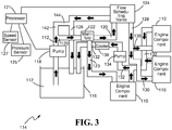
- the main pump 118 may be regulated by a processor 121 to regulate the flow of lubricant 112 according to an operational speed of the engine 100, as in FIG. 3 .
- the lubrication system 114 may have a main conduit 120 from the main pump 118 to the engine component 110.
- the main pump 118 may pump the lubricant 112 through the main conduit 120 to each component 110.
- a flow scheduling valve 124 is positioned in the main conduit 120 between the main pump 118 and the engine component 110, such as the engine gearbox.
- the flow scheduling valve 124 may regulate the flow of lubricant 112 directly from the main pump 118 to at least one component 110 such that all such components 110 may receive a reduced flow of lubricant 112 based on a calculated engine load.
- the engine load may be calculated by the processor 121 from any suitable parameter such as, but not limited to, a combustor pressure, a fan speed, an engine horsepower, or the like.
- the combustor pressure may be measured by a pressure sensor 125 in the combustor 104 and the fan speed may be measured by a speed sensor 127, for example.
- the processor 121 may direct the valve 124 to reduce the flow of lubricant 112 to the engine component 110 by an equivalent percentage.
- the lubrication system 114 may also have a scavenge conduit 132 from each of the components 110 to the lubricant tank 116 for returning the used lubricant 112 to the lubricant tank 116.
- At least one scavenge pump 134, for pumping lubricant 112 from the components 110 to the lubricant tank 116, may be provided in connection with the scavenge conduit 132.
- a lubricant cooler 138 may be positioned in the main conduit 120 or in the scavenge conduit 132 and may remove heat gained from the engine component 110 from the lubricant 112.
- the lubricant cooler 138 may operate by allowing compressed air or fuel to draw heat from the lubricant 112 through at least one wall of the lubricant cooler 138 or by any other known method.
- a lubricant filter (not shown) and/or a de-aerator (not shown) may also be positioned in the main conduit 120 or the scavenge conduit 132.
- the lubricant filter may remove unwanted debris from the lubricant 112, such as coked lubricant, for example.
- the de-aerator may separate unwanted air entrained in the lubricant 112 which may have been combined while the lubricant 112 acted on the engine component 110.
- the lubrication system 114 described above may be further modified as in FIG. 3 .
- Many elements are similar to the embodiment of FIG. 2 , but it will be noted that a manifold 122 may be positioned between the main pump 118 and the flow scheduling valve 124 in the main conduit 120.
- the manifold may direct a portion of the lubricant 112 through a side conduit 123 to a first engine component 110.
- the engine component 110 may receive a flow of lubricant 112 not reduced by the flow scheduling valve 124.
- the flow scheduling valve 124 may redirect any excess lubricant 112 through a return conduit 126 to the lubricant tank 116.
- the main conduit 120 between the flow scheduling valve 124 and the engine component 110 may have a primary conduit 128 which accepts the full flow of lubricant 112 exiting from the flow scheduling valve 124. At least one secondary conduit 130 branching from the primary conduit 128 may also be provided. Each secondary conduit 130 may lead to another engine component 110 and be constructed to receive a pre-determined percentage of the total lubricant 112 from the flow scheduling valve 124.
- a fixed flow metering orifice 142 may be positioned in the main conduit 120 between the main pump 118 and the engine components 110.
- the metering orifice 142 may allow a constant percentage of the lubricant 112 to bypass the entire lubrication system 114, which may prevent the lubricant 112 from backing up in the main conduit 120.
- the metering orifice 142 may allow this excess lubricant 112 to return to the lubricant tank 116 by a bypass conduit 144.
- a regulating valve may also allow the lubricant to bypass the lubrication system in a similar manner.
- the lubrication system 114 is able to lubricate the gas turbine engine 100 according to the method depicted in FIG. 4 .
- the main pump 118 pumps lubricant 112 from the lubricant tank 116 into the main conduit 120.
- the lubricant is passed through the main conduit 120 to a lubricant cooler to remove excess heat from the lubricant which may have been gained by previously acting on engine components 110, as in a step 202.
- the cooled lubricant is then passed to the flow scheduling valve 124, as shown by a step 204.
- the pressure of the combustor 104 and speed of the fan 101 are then both measured by sensors in the engine 100 as shown by steps 206 and 208, respectively, and a load condition of the engine 100 is calculated from the measured values at a step 210. If the load condition is at a maximum as determined by a step 212, all of the lubricant 112 is allowed to pass through the flow scheduling valve 124 as shown at a step 214. However, if the load condition is less than maximum the lubricant flow is reduced by the valve 124 as at step 216. In such a case, excess lubricant 112 is then redirected back to the lubricant tank at a step 218, while a reduced amount of lubricant 112 is passed through the valve 124. In this embodiment, all lubricant 112 passing the valve 124 flows through the main conduit 120 to the engine component 110, where the lubricant 112 lubricates or removes heat from the component 110.
- the used lubricant 112 is pumped from the engine components 110 into a scavenge conduit 134 at a step 220.
- the lubricant 112 is returned through the scavenge conduit 134 to the lubricant tank 116 at a step 222. Once the lubricant 112 reaches the tank 116 it is once again pumped into the main conduit 120 by the main pump 118.
- the lubrication system disclosed herein has industrial applicability in a variety of settings such as, but not limited to lubricating and cooling gas turbine engines.
- the lubrication system may increase the efficiency of the engine by reducing energy consumption which would heretofore have been spent on churning excess lubricant during low load conditions.
- the lubrication system may also increase the efficiency of the engine by reducing the necessary cooling of the lubricant and thus minimizing the size of the lubricant cooler. Minimizing the size of the lubricant cooler may reduce weight of the engine and/or air drag, further improving performance.
Landscapes
- Engineering & Computer Science (AREA)
- Mechanical Engineering (AREA)
- General Engineering & Computer Science (AREA)
- Chemical & Material Sciences (AREA)
- Combustion & Propulsion (AREA)
- Lubrication Of Internal Combustion Engines (AREA)
Claims (14)
- Gasturbinentriebwerk, das ein Schmiersystem aufweist, wobei das Schmiersystem Folgendes umfasst:eine Hauptpumpe (118) zum Bewegen eines Schmiermittels (112) durch eine Hauptleitung (120) von einem Schmiermitteltank (116) zu einem Triebwerksbauteil (110);ein Strömungsplanungsventil (124), das in der Hauptleitung (120) zwischen der Hauptpumpe (118) und dem Triebwerksbauteil (110) positioniert ist; undeinen Prozessor (121), der mit dem Strömungsplanungsventil (124) und mit einem Sensor (125/127) verbunden ist, der einen gemessenen Wert bereitstellt, den der Prozessor (121) dazu verwendet, eine Triebwerksbelastung zu berechnen,dadurch gekennzeichnet, dass:der Prozessor (121) dazu konfiguriert ist, das Strömungsplanungsventil (124) selektiv dazu zu steuern, eine Strömung von Schmiermittel (112) an das Triebwerksbauteil (110) zu begrenzen und überschüssiges Schmiermittel (112) durch eine Rückführleitung (132) zu dem Schmiermitteltank (116) umzuleiten als Reaktion darauf, dass die Triebwerksbelastung geringer ist als ein Schwellenwert einer Maximalbelastung, undder Prozessor (121) dazu konfiguriert ist, das Strömungsplanungsventil (124) selektiv dazu zu steuern, eine vollständige Strömung des Schmiermittels (112) zu dem Triebwerksbauteil (110) zu ermöglichen als Reaktion darauf, dass die Triebwerksbelastung gleich dem Schwellenwert der Maximalbelastung oder größer als dieser ist.
- Gasturbinentriebwerk nach Anspruch 1, wobei das Schmiersystem ferner einen Schmiermittelkühler (138) umfasst, der mit einer Hauptleitung (120) verbunden ist.
- Gasturbinentriebwerk nach Anspruch 2, wobei der Schmiermittelkühler (138) zwischen der Hauptpumpe (118) und dem Triebwerksbauteil (110) positioniert ist.
- Gasturbinentriebwerk nach einem der vorhergehenden Ansprüche, wobei das Schmiersystem ferner eine Messöffnung (142) einer festen Strömung umfasst, die in der Hauptleitung (120) zwischen der Hauptpumpe (118) und dem Triebwerksbauteil (110) angeordnet ist, wobei die Messöffnung (142) es dem Schmiermittel (112) ermöglicht, das Triebwerksbauteil (110) über eine Bypassleitung (144) zu umgehen und zu dem Schmiermitteltank (116) zurückzukehren.
- Gasturbinentriebwerk nach einem der vorhergehenden Ansprüche, wobei die berechnete Triebwerksbelastung durch den Prozessor (121) auf der Basis eines Brennkammerdrucks und/oder einer Fangeschwindigkeit, die von einem Geschwindigkeitssensor (127) gemessen wird, berechnet wird.
- Gasturbinentriebwerk nach einem der vorhergehenden Ansprüche, wobei ein Betrieb der Hauptpumpe (118) durch eine Triebwerksgeschwindigkeit reguliert ist.
- Gasturbinentriebwerk nach einem der vorhergehenden Ansprüche, wobei das Schmiersystem ferner einen Verteiler (122) umfasst, der in der Hauptleitung (120) zwischen der Hauptpumpe (118) und dem Strömungsplanungsventil (124) positioniert ist, wobei der Verteiler (122) mit dem Triebwerksbauteil (110) über eine Seitenleitung (123) verbunden ist, um es dem Triebwerkbauteil (110) zu ermöglichen, eine Schmiermittelströmung zu empfangen, die nicht durch das Strömungsplanungsventil (124) reduziert ist.
- Gasturbinentriebwerk nach einem der vorhergehenden Ansprüche, das ferner Folgendes umfasst:einen Verdichter (102);eine Brennkammer (104) stromabwärts des Verdichters (102); undeine Turbine (106) stromabwärts der Brennkammer (104).
- Gasturbinentriebwerk nach Anspruch 8, wobei ein Betrieb der Hauptpumpe (118) gegebenenfalls durch einen Antriebsstrang angetrieben wird, der mechanisch mit einem Triebwerksrotor verbunden ist.
- Gasturbinentriebwerk nach Anspruch 8 oder 9, wobei die Belastung auf das Triebwerksbauteil (110) durch den Prozessor (121) auf der Basis eines Parameters berechnet wird, der von einem von einem Drucksensor (125) und einem Geschwindigkeitssensor (127) gemessen wird.
- Verfahren zum Schmieren eines Bauteils eines Gasturbinentriebwerks, wobei das Verfahren Folgendes umfasst:Pumpen eines Schmiermittels (112) von einem Schmiermitteltank (116) durch eine Hauptleitung (120) an ein Triebwerksbauteil (110) durch eine Hauptpumpe (118);Berechnen einer Triebwerksbelastung unter Verwendung eines gemessenen Werts, der durch einen Sensor (125/127) bereitgestellt wird,dadurch gekennzeichnet, dass es ferner Folgendes umfasst:selektives Steuern eines Strömungsplanungsventils (124) dazu, eine Strömung des Schmiermittels (112) an das Triebwerksbauteil (110) zu begrenzen und Umleiten von überschüssigem Schmiermittel (112) durch eine Rückführleitung (132) an den Schmiermitteltank (116) als Reaktion darauf, dass die Triebwerksbelastung geringer ist als ein Schwellenwert einer Maximalbelastung; undselektives Steuern des Strömungsplanungsventils (124) dazu, eine vollständige Strömung des Schmiermittels (112) an das Triebwerksbauteil (110) zu ermöglichen als Reaktion darauf, dass die Triebwerksbelastung gleich dem Schwellenwert der Maximalbelastung oder größer als dieser ist.
- Verfahren nach Anspruch 11, ferner umfassend ein Leiten von überschüssigem Schmiermittel (112) von dem Strömungsplanungsventil (124) durch die Rückführleitung (132) zu dem Schmiermitteltank (116) mit Hilfe des Strömungsplanungsventils (124).
- Verfahren nach Anspruch 11 oder 12, ferner umfassend ein Messen von:dem Triebwerksbrennkammerdruck und Berechnen der Belastung des Triebwerks durch den Prozessor (121) auf der Basis des gemessenen Brennkammerdrucks; und/oderder Triebwerksfangeschwindigkeit und Berechnen der Belastung des Triebwerks durch den Prozessor (121) auf der Basis der gemessenen Fangeschwindigkeit.
- Verfahren nach einem der Ansprüche 11, 12 oder 13, ferner umfassend:Regulieren der Schmiermittelströmung von der Hauptpumpe (118) auf der Basis einer Betriebsgeschwindigkeit des Gasturbinentriebwerks; und/oderUmleiten von Schmiermittel (112) von der Hauptleitung (120) durch die Bypassleitung (144) zu dem Schmiermitteltank (116).
Applications Claiming Priority (2)
| Application Number | Priority Date | Filing Date | Title |
|---|---|---|---|
| US13/690,767 US10107197B2 (en) | 2012-11-30 | 2012-11-30 | Lubrication system for gas turbine engines |
| PCT/US2013/068275 WO2014085031A2 (en) | 2012-11-30 | 2013-11-04 | Lubrication system for gas turbine engines |
Publications (3)
| Publication Number | Publication Date |
|---|---|
| EP2925974A2 EP2925974A2 (de) | 2015-10-07 |
| EP2925974A4 EP2925974A4 (de) | 2016-07-20 |
| EP2925974B1 true EP2925974B1 (de) | 2019-05-15 |
Family
ID=50824073
Family Applications (1)
| Application Number | Title | Priority Date | Filing Date |
|---|---|---|---|
| EP13858861.1A Active EP2925974B1 (de) | 2012-11-30 | 2013-11-04 | Gasturbine mit einem schmiersystem sowie verfahren |
Country Status (3)
| Country | Link |
|---|---|
| US (2) | US10107197B2 (de) |
| EP (1) | EP2925974B1 (de) |
| WO (1) | WO2014085031A2 (de) |
Families Citing this family (15)
| Publication number | Priority date | Publication date | Assignee | Title |
|---|---|---|---|---|
| US10107197B2 (en) | 2012-11-30 | 2018-10-23 | United Technologies Corporation | Lubrication system for gas turbine engines |
| WO2015126500A1 (en) * | 2013-12-05 | 2015-08-27 | Mastro Jacob P | Fdgs auxiliary pump monitoring system |
| US9874145B2 (en) * | 2015-04-27 | 2018-01-23 | United Technologies Corporation | Lubrication system for gas turbine engines |
| US10260420B2 (en) | 2015-05-19 | 2019-04-16 | Rolls-Royce Corporation | Lubrication system for a reconfigurable gas turbine engine |
| US10145276B2 (en) | 2015-06-23 | 2018-12-04 | United Technologies Corporation | Lubricant valve monitoring method and assembly |
| US10619567B2 (en) | 2016-04-29 | 2020-04-14 | Rolls-Royce Corporation | Reconfigurable lubrication system for multiple powertrain orientations |
| US10458278B2 (en) * | 2016-11-04 | 2019-10-29 | United Technologies Corporation | Apparatus and method for providing fluid to a bearing damper |
| US10711642B2 (en) * | 2017-03-31 | 2020-07-14 | Raytheon Technologies Corporation | Gas turbine engine lubrication system and apparatus with boost pump system |
| US11918934B2 (en) * | 2017-06-05 | 2024-03-05 | Rtx Corporation | Oil filtration system |
| CN108846144B (zh) * | 2018-03-30 | 2021-10-08 | 同济大学 | 一种不依赖于流量计的管路流量在线检测方法 |
| US11236637B2 (en) | 2018-12-21 | 2022-02-01 | Raytheon Technologies Corporation | Auxiliary lubrication system with flow management valve |
| US11415051B2 (en) * | 2020-12-22 | 2022-08-16 | General Electric Company | System for lubricating components of a gas turbine engine including a lubricant bypass conduit |
| US11761350B2 (en) | 2021-03-31 | 2023-09-19 | General Electric Company | Lubrication system for aerial vehicles |
| US12146441B1 (en) * | 2023-07-13 | 2024-11-19 | General Electric Company | Methods and apparatus to maintain a state of a fluid in a system |
| FR3163405A1 (fr) * | 2024-06-12 | 2025-12-19 | Safran Aircraft Engines | Système de lubrification d’enceintes d’une turbomachine |
Family Cites Families (23)
| Publication number | Priority date | Publication date | Assignee | Title |
|---|---|---|---|---|
| US2578275A (en) * | 1949-09-30 | 1951-12-11 | Irvin R Whiteman | Air-free lubricant pump discharge system |
| US4380146A (en) | 1977-01-12 | 1983-04-19 | Westinghouse Electric Corp. | System and method for accelerating and sequencing industrial gas turbine apparatus and gas turbine electric power plants preferably with a digital computer control system |
| DE2932081A1 (de) | 1979-07-11 | 1981-01-29 | Bbc Brown Boveri & Cie | Bypassteuereinrichtung fuer turboaufgeladene verbrennungsmotoren |
| US5307865A (en) | 1987-02-06 | 1994-05-03 | Honda Giken Kogyo Kabushiki Kaisha | Engine oil cooling system |
| US5067454A (en) * | 1989-06-14 | 1991-11-26 | Avco Corporation | Self compensating flow control lubrication system |
| US5339776A (en) * | 1993-08-30 | 1994-08-23 | Chrysler Corporation | Lubrication system with an oil bypass valve |
| US6058694A (en) * | 1997-11-11 | 2000-05-09 | Alliedsignal Inc. | Gas turbine engine commanded oil flow valve with failsafe |
| EP1130221A1 (de) * | 2000-02-14 | 2001-09-05 | Techspace Aero S.A. | Vorrichtung und Verfahren Schmierung von aeronautische Brennkraftmaschine |
| US6459963B1 (en) * | 2000-07-31 | 2002-10-01 | General Electric Company | Methods and apparatus for trimming engine control systems |
| JP3958054B2 (ja) * | 2002-01-31 | 2007-08-15 | 株式会社東芝 | 回転機械の軸受油循環系統の改修方法 |
| US7055306B2 (en) * | 2003-04-30 | 2006-06-06 | Hamilton Sundstrand Corporation | Combined stage single shaft turbofan engine |
| GB0318400D0 (en) | 2003-08-06 | 2003-09-10 | Rolls Royce Plc | A fluid system |
| US7506724B2 (en) * | 2004-07-23 | 2009-03-24 | Honeywell International Inc. | Active gas turbine lubrication system flow control |
| JP4699130B2 (ja) * | 2005-08-03 | 2011-06-08 | 三菱重工業株式会社 | ガスタービンの入口案内翼制御装置 |
| US8424646B2 (en) * | 2006-07-10 | 2013-04-23 | United Technologies Corporation | Interruption tolerant lubrication system |
| US7886875B2 (en) * | 2007-07-11 | 2011-02-15 | United Technologies Corp. | Systems and methods for monitoring gas turbine engines |
| GB0820174D0 (en) * | 2008-11-05 | 2008-12-10 | Rolls Royce Plc | A gas turbine engine variable area exhaust nozzle |
| US8230974B2 (en) | 2009-05-22 | 2012-07-31 | United Technologies Corporation | Windmill and zero gravity lubrication system for a gas turbine engine |
| US20110147322A1 (en) * | 2009-12-17 | 2011-06-23 | Honeywell International Inc. | Lubricant supply filtration system and method |
| IT1403788B1 (it) * | 2010-12-29 | 2013-10-31 | Ansaldo Energia Spa | Metodo per controllare un impianto a ciclo combinato in configurazione "single-shaft" e impianto a ciclo combinato in configurazione "single-shaft" |
| US8408233B2 (en) | 2011-03-18 | 2013-04-02 | Hamilton Sundstrand Corporation | Flow control system and method for controlling two positive displacement pumps |
| US8261527B1 (en) * | 2012-01-31 | 2012-09-11 | United Technologies Corporation | Gas turbine engine with geared turbofan and oil thermal management system with unique heat exchanger structure |
| US10107197B2 (en) | 2012-11-30 | 2018-10-23 | United Technologies Corporation | Lubrication system for gas turbine engines |
-
2012
- 2012-11-30 US US13/690,767 patent/US10107197B2/en active Active
-
2013
- 2013-11-04 WO PCT/US2013/068275 patent/WO2014085031A2/en not_active Ceased
- 2013-11-04 EP EP13858861.1A patent/EP2925974B1/de active Active
-
2018
- 2018-10-22 US US16/167,048 patent/US11193422B2/en active Active
Non-Patent Citations (1)
| Title |
|---|
| None * |
Also Published As
| Publication number | Publication date |
|---|---|
| US20140150439A1 (en) | 2014-06-05 |
| EP2925974A4 (de) | 2016-07-20 |
| WO2014085031A2 (en) | 2014-06-05 |
| US10107197B2 (en) | 2018-10-23 |
| WO2014085031A3 (en) | 2014-08-07 |
| US11193422B2 (en) | 2021-12-07 |
| EP2925974A2 (de) | 2015-10-07 |
| US20190055886A1 (en) | 2019-02-21 |
Similar Documents
| Publication | Publication Date | Title |
|---|---|---|
| US11193422B2 (en) | Lubrication system for gas turbine engines | |
| EP3088688B1 (de) | Schmiersystem für gasturbinenmotoren | |
| US11549399B2 (en) | Controlling lubricant flow in epicyclic gearbox | |
| US10823005B2 (en) | Lubrication system for a turbine engine | |
| EP3730763A1 (de) | Dynamische thermische lastüberwachung und -minderung für flugzeugsysteme | |
| US9062611B2 (en) | Split accessory drive system | |
| EP3246531B1 (de) | Ölverkokungsabschwächung in einem gasturbinenmotor | |
| EP2565396B1 (de) | Verteiltes Schmiersystem | |
| US20220154600A1 (en) | Pneumatic starter supplemental lubrication system | |
| US12305522B2 (en) | Turbomachine lubrication system comprising a bypass for preferentially supplying lubricant to a low-speed reduction gear | |
| EP2959129A2 (de) | In eine schmiermittelhauptpumpstufe integrierte zusätzliche schmiermittelversorgungspumpstufe | |
| US10060290B2 (en) | Method and system for centrifugal pump |
Legal Events
| Date | Code | Title | Description |
|---|---|---|---|
| PUAI | Public reference made under article 153(3) epc to a published international application that has entered the european phase |
Free format text: ORIGINAL CODE: 0009012 |
|
| 17P | Request for examination filed |
Effective date: 20150625 |
|
| AK | Designated contracting states |
Kind code of ref document: A2 Designated state(s): AL AT BE BG CH CY CZ DE DK EE ES FI FR GB GR HR HU IE IS IT LI LT LU LV MC MK MT NL NO PL PT RO RS SE SI SK SM TR |
|
| AX | Request for extension of the european patent |
Extension state: BA ME |
|
| RIN1 | Information on inventor provided before grant (corrected) |
Inventor name: DALEY, DAVID, M. Inventor name: CLARK, RICHARD, W. Inventor name: JAMES, DENMAN, H. Inventor name: PARNIN, FRANCIS Inventor name: DOLMAN, PAUL, H. |
|
| RIN1 | Information on inventor provided before grant (corrected) |
Inventor name: JAMES, DENMAN, H. Inventor name: CLARK, RICHARD, W. Inventor name: DALEY, DAVID, M. Inventor name: PARNIN, FRANCIS Inventor name: DOLMAN, PAUL, H. |
|
| RIN1 | Information on inventor provided before grant (corrected) |
Inventor name: JAMES, DENMAN, H. Inventor name: DALEY, DAVID, M. Inventor name: CLARK, RICHARD, W. Inventor name: PARNIN, FRANCIS Inventor name: DOLMAN, PAUL, H. |
|
| DAX | Request for extension of the european patent (deleted) | ||
| A4 | Supplementary search report drawn up and despatched |
Effective date: 20160616 |
|
| RIC1 | Information provided on ipc code assigned before grant |
Ipc: F01D 25/18 20060101ALI20160610BHEP Ipc: F01D 25/20 20060101ALI20160610BHEP Ipc: F01D 25/00 20060101AFI20160610BHEP |
|
| RAP1 | Party data changed (applicant data changed or rights of an application transferred) |
Owner name: UNITED TECHNOLOGIES CORPORATION |
|
| GRAP | Despatch of communication of intention to grant a patent |
Free format text: ORIGINAL CODE: EPIDOSNIGR1 |
|
| STAA | Information on the status of an ep patent application or granted ep patent |
Free format text: STATUS: GRANT OF PATENT IS INTENDED |
|
| INTG | Intention to grant announced |
Effective date: 20181121 |
|
| GRAS | Grant fee paid |
Free format text: ORIGINAL CODE: EPIDOSNIGR3 |
|
| GRAA | (expected) grant |
Free format text: ORIGINAL CODE: 0009210 |
|
| STAA | Information on the status of an ep patent application or granted ep patent |
Free format text: STATUS: THE PATENT HAS BEEN GRANTED |
|
| AK | Designated contracting states |
Kind code of ref document: B1 Designated state(s): AL AT BE BG CH CY CZ DE DK EE ES FI FR GB GR HR HU IE IS IT LI LT LU LV MC MK MT NL NO PL PT RO RS SE SI SK SM TR |
|
| REG | Reference to a national code |
Ref country code: CH Ref legal event code: EP |
|
| REG | Reference to a national code |
Ref country code: IE Ref legal event code: FG4D |
|
| REG | Reference to a national code |
Ref country code: DE Ref legal event code: R096 Ref document number: 602013055570 Country of ref document: DE |
|
| REG | Reference to a national code |
Ref country code: NL Ref legal event code: MP Effective date: 20190515 |
|
| REG | Reference to a national code |
Ref country code: LT Ref legal event code: MG4D |
|
| PG25 | Lapsed in a contracting state [announced via postgrant information from national office to epo] |
Ref country code: AL Free format text: LAPSE BECAUSE OF FAILURE TO SUBMIT A TRANSLATION OF THE DESCRIPTION OR TO PAY THE FEE WITHIN THE PRESCRIBED TIME-LIMIT Effective date: 20190515 Ref country code: ES Free format text: LAPSE BECAUSE OF FAILURE TO SUBMIT A TRANSLATION OF THE DESCRIPTION OR TO PAY THE FEE WITHIN THE PRESCRIBED TIME-LIMIT Effective date: 20190515 Ref country code: NO Free format text: LAPSE BECAUSE OF FAILURE TO SUBMIT A TRANSLATION OF THE DESCRIPTION OR TO PAY THE FEE WITHIN THE PRESCRIBED TIME-LIMIT Effective date: 20190815 Ref country code: PT Free format text: LAPSE BECAUSE OF FAILURE TO SUBMIT A TRANSLATION OF THE DESCRIPTION OR TO PAY THE FEE WITHIN THE PRESCRIBED TIME-LIMIT Effective date: 20190915 Ref country code: HR Free format text: LAPSE BECAUSE OF FAILURE TO SUBMIT A TRANSLATION OF THE DESCRIPTION OR TO PAY THE FEE WITHIN THE PRESCRIBED TIME-LIMIT Effective date: 20190515 Ref country code: SE Free format text: LAPSE BECAUSE OF FAILURE TO SUBMIT A TRANSLATION OF THE DESCRIPTION OR TO PAY THE FEE WITHIN THE PRESCRIBED TIME-LIMIT Effective date: 20190515 Ref country code: LT Free format text: LAPSE BECAUSE OF FAILURE TO SUBMIT A TRANSLATION OF THE DESCRIPTION OR TO PAY THE FEE WITHIN THE PRESCRIBED TIME-LIMIT Effective date: 20190515 Ref country code: NL Free format text: LAPSE BECAUSE OF FAILURE TO SUBMIT A TRANSLATION OF THE DESCRIPTION OR TO PAY THE FEE WITHIN THE PRESCRIBED TIME-LIMIT Effective date: 20190515 Ref country code: FI Free format text: LAPSE BECAUSE OF FAILURE TO SUBMIT A TRANSLATION OF THE DESCRIPTION OR TO PAY THE FEE WITHIN THE PRESCRIBED TIME-LIMIT Effective date: 20190515 |
|
| PG25 | Lapsed in a contracting state [announced via postgrant information from national office to epo] |
Ref country code: LV Free format text: LAPSE BECAUSE OF FAILURE TO SUBMIT A TRANSLATION OF THE DESCRIPTION OR TO PAY THE FEE WITHIN THE PRESCRIBED TIME-LIMIT Effective date: 20190515 Ref country code: RS Free format text: LAPSE BECAUSE OF FAILURE TO SUBMIT A TRANSLATION OF THE DESCRIPTION OR TO PAY THE FEE WITHIN THE PRESCRIBED TIME-LIMIT Effective date: 20190515 Ref country code: BG Free format text: LAPSE BECAUSE OF FAILURE TO SUBMIT A TRANSLATION OF THE DESCRIPTION OR TO PAY THE FEE WITHIN THE PRESCRIBED TIME-LIMIT Effective date: 20190815 Ref country code: GR Free format text: LAPSE BECAUSE OF FAILURE TO SUBMIT A TRANSLATION OF THE DESCRIPTION OR TO PAY THE FEE WITHIN THE PRESCRIBED TIME-LIMIT Effective date: 20190816 |
|
| REG | Reference to a national code |
Ref country code: AT Ref legal event code: MK05 Ref document number: 1133683 Country of ref document: AT Kind code of ref document: T Effective date: 20190515 |
|
| PG25 | Lapsed in a contracting state [announced via postgrant information from national office to epo] |
Ref country code: SK Free format text: LAPSE BECAUSE OF FAILURE TO SUBMIT A TRANSLATION OF THE DESCRIPTION OR TO PAY THE FEE WITHIN THE PRESCRIBED TIME-LIMIT Effective date: 20190515 Ref country code: EE Free format text: LAPSE BECAUSE OF FAILURE TO SUBMIT A TRANSLATION OF THE DESCRIPTION OR TO PAY THE FEE WITHIN THE PRESCRIBED TIME-LIMIT Effective date: 20190515 Ref country code: DK Free format text: LAPSE BECAUSE OF FAILURE TO SUBMIT A TRANSLATION OF THE DESCRIPTION OR TO PAY THE FEE WITHIN THE PRESCRIBED TIME-LIMIT Effective date: 20190515 Ref country code: AT Free format text: LAPSE BECAUSE OF FAILURE TO SUBMIT A TRANSLATION OF THE DESCRIPTION OR TO PAY THE FEE WITHIN THE PRESCRIBED TIME-LIMIT Effective date: 20190515 Ref country code: CZ Free format text: LAPSE BECAUSE OF FAILURE TO SUBMIT A TRANSLATION OF THE DESCRIPTION OR TO PAY THE FEE WITHIN THE PRESCRIBED TIME-LIMIT Effective date: 20190515 Ref country code: RO Free format text: LAPSE BECAUSE OF FAILURE TO SUBMIT A TRANSLATION OF THE DESCRIPTION OR TO PAY THE FEE WITHIN THE PRESCRIBED TIME-LIMIT Effective date: 20190515 |
|
| REG | Reference to a national code |
Ref country code: DE Ref legal event code: R097 Ref document number: 602013055570 Country of ref document: DE |
|
| PG25 | Lapsed in a contracting state [announced via postgrant information from national office to epo] |
Ref country code: IT Free format text: LAPSE BECAUSE OF FAILURE TO SUBMIT A TRANSLATION OF THE DESCRIPTION OR TO PAY THE FEE WITHIN THE PRESCRIBED TIME-LIMIT Effective date: 20190515 Ref country code: SM Free format text: LAPSE BECAUSE OF FAILURE TO SUBMIT A TRANSLATION OF THE DESCRIPTION OR TO PAY THE FEE WITHIN THE PRESCRIBED TIME-LIMIT Effective date: 20190515 |
|
| PLBE | No opposition filed within time limit |
Free format text: ORIGINAL CODE: 0009261 |
|
| STAA | Information on the status of an ep patent application or granted ep patent |
Free format text: STATUS: NO OPPOSITION FILED WITHIN TIME LIMIT |
|
| PG25 | Lapsed in a contracting state [announced via postgrant information from national office to epo] |
Ref country code: TR Free format text: LAPSE BECAUSE OF FAILURE TO SUBMIT A TRANSLATION OF THE DESCRIPTION OR TO PAY THE FEE WITHIN THE PRESCRIBED TIME-LIMIT Effective date: 20190515 |
|
| 26N | No opposition filed |
Effective date: 20200218 |
|
| PG25 | Lapsed in a contracting state [announced via postgrant information from national office to epo] |
Ref country code: PL Free format text: LAPSE BECAUSE OF FAILURE TO SUBMIT A TRANSLATION OF THE DESCRIPTION OR TO PAY THE FEE WITHIN THE PRESCRIBED TIME-LIMIT Effective date: 20190515 |
|
| PG25 | Lapsed in a contracting state [announced via postgrant information from national office to epo] |
Ref country code: SI Free format text: LAPSE BECAUSE OF FAILURE TO SUBMIT A TRANSLATION OF THE DESCRIPTION OR TO PAY THE FEE WITHIN THE PRESCRIBED TIME-LIMIT Effective date: 20190515 |
|
| REG | Reference to a national code |
Ref country code: CH Ref legal event code: PL |
|
| PG25 | Lapsed in a contracting state [announced via postgrant information from national office to epo] |
Ref country code: LU Free format text: LAPSE BECAUSE OF NON-PAYMENT OF DUE FEES Effective date: 20191104 Ref country code: MC Free format text: LAPSE BECAUSE OF FAILURE TO SUBMIT A TRANSLATION OF THE DESCRIPTION OR TO PAY THE FEE WITHIN THE PRESCRIBED TIME-LIMIT Effective date: 20190515 Ref country code: LI Free format text: LAPSE BECAUSE OF NON-PAYMENT OF DUE FEES Effective date: 20191130 Ref country code: CH Free format text: LAPSE BECAUSE OF NON-PAYMENT OF DUE FEES Effective date: 20191130 |
|
| REG | Reference to a national code |
Ref country code: BE Ref legal event code: MM Effective date: 20191130 |
|
| PG25 | Lapsed in a contracting state [announced via postgrant information from national office to epo] |
Ref country code: IE Free format text: LAPSE BECAUSE OF NON-PAYMENT OF DUE FEES Effective date: 20191104 |
|
| PG25 | Lapsed in a contracting state [announced via postgrant information from national office to epo] |
Ref country code: BE Free format text: LAPSE BECAUSE OF NON-PAYMENT OF DUE FEES Effective date: 20191130 |
|
| PG25 | Lapsed in a contracting state [announced via postgrant information from national office to epo] |
Ref country code: CY Free format text: LAPSE BECAUSE OF FAILURE TO SUBMIT A TRANSLATION OF THE DESCRIPTION OR TO PAY THE FEE WITHIN THE PRESCRIBED TIME-LIMIT Effective date: 20190515 |
|
| PG25 | Lapsed in a contracting state [announced via postgrant information from national office to epo] |
Ref country code: IS Free format text: LAPSE BECAUSE OF FAILURE TO SUBMIT A TRANSLATION OF THE DESCRIPTION OR TO PAY THE FEE WITHIN THE PRESCRIBED TIME-LIMIT Effective date: 20190915 |
|
| PG25 | Lapsed in a contracting state [announced via postgrant information from national office to epo] |
Ref country code: MT Free format text: LAPSE BECAUSE OF FAILURE TO SUBMIT A TRANSLATION OF THE DESCRIPTION OR TO PAY THE FEE WITHIN THE PRESCRIBED TIME-LIMIT Effective date: 20190515 Ref country code: HU Free format text: LAPSE BECAUSE OF FAILURE TO SUBMIT A TRANSLATION OF THE DESCRIPTION OR TO PAY THE FEE WITHIN THE PRESCRIBED TIME-LIMIT; INVALID AB INITIO Effective date: 20131104 |
|
| PG25 | Lapsed in a contracting state [announced via postgrant information from national office to epo] |
Ref country code: MK Free format text: LAPSE BECAUSE OF FAILURE TO SUBMIT A TRANSLATION OF THE DESCRIPTION OR TO PAY THE FEE WITHIN THE PRESCRIBED TIME-LIMIT Effective date: 20190515 |
|
| REG | Reference to a national code |
Ref country code: DE Ref legal event code: R081 Ref document number: 602013055570 Country of ref document: DE Owner name: RAYTHEON TECHNOLOGIES CORPORATION (N.D.GES.D.S, US Free format text: FORMER OWNER: UNITED TECHNOLOGIES CORPORATION, FARMINGTON, CONN., US Ref country code: DE Ref legal event code: R081 Ref document number: 602013055570 Country of ref document: DE Owner name: RTX CORPORATION (N.D.GES.D. STAATES DELAWARE),, US Free format text: FORMER OWNER: UNITED TECHNOLOGIES CORPORATION, FARMINGTON, CONN., US |
|
| P01 | Opt-out of the competence of the unified patent court (upc) registered |
Effective date: 20230520 |
|
| REG | Reference to a national code |
Ref country code: DE Ref legal event code: R081 Ref document number: 602013055570 Country of ref document: DE Owner name: RTX CORPORATION (N.D.GES.D. STAATES DELAWARE),, US Free format text: FORMER OWNER: RAYTHEON TECHNOLOGIES CORPORATION (N.D.GES.D.STAATES DELAWARE), ARLINGTON, VA, US |
|
| PGFP | Annual fee paid to national office [announced via postgrant information from national office to epo] |
Ref country code: DE Payment date: 20251022 Year of fee payment: 13 |
|
| PGFP | Annual fee paid to national office [announced via postgrant information from national office to epo] |
Ref country code: GB Payment date: 20251023 Year of fee payment: 13 |
|
| PGFP | Annual fee paid to national office [announced via postgrant information from national office to epo] |
Ref country code: FR Payment date: 20251022 Year of fee payment: 13 |