EP2927381A1 - Structure de bâtiment formée d'éléments de construction - Google Patents
Structure de bâtiment formée d'éléments de construction Download PDFInfo
- Publication number
- EP2927381A1 EP2927381A1 EP15159450.4A EP15159450A EP2927381A1 EP 2927381 A1 EP2927381 A1 EP 2927381A1 EP 15159450 A EP15159450 A EP 15159450A EP 2927381 A1 EP2927381 A1 EP 2927381A1
- Authority
- EP
- European Patent Office
- Prior art keywords
- building
- building elements
- joint
- elements
- valleys
- Prior art date
- Legal status (The legal status is an assumption and is not a legal conclusion. Google has not performed a legal analysis and makes no representation as to the accuracy of the status listed.)
- Granted
Links
- 230000015572 biosynthetic process Effects 0.000 claims abstract description 54
- 238000005755 formation reaction Methods 0.000 claims abstract description 54
- 238000000034 method Methods 0.000 claims abstract description 12
- 230000000295 complement effect Effects 0.000 claims abstract description 11
- 238000005516 engineering process Methods 0.000 description 30
- 239000000463 material Substances 0.000 description 10
- 230000032258 transport Effects 0.000 description 5
- 238000013461 design Methods 0.000 description 4
- 238000005452 bending Methods 0.000 description 3
- 238000009434 installation Methods 0.000 description 3
- 238000012986 modification Methods 0.000 description 3
- 230000004048 modification Effects 0.000 description 3
- 238000005266 casting Methods 0.000 description 2
- 239000002131 composite material Substances 0.000 description 2
- 238000005304 joining Methods 0.000 description 2
- 238000004519 manufacturing process Methods 0.000 description 2
- 238000003860 storage Methods 0.000 description 2
- 229910000831 Steel Inorganic materials 0.000 description 1
- 238000010276 construction Methods 0.000 description 1
- 230000001419 dependent effect Effects 0.000 description 1
- 238000011161 development Methods 0.000 description 1
- 230000018109 developmental process Effects 0.000 description 1
- 230000000694 effects Effects 0.000 description 1
- 238000010438 heat treatment Methods 0.000 description 1
- 230000001788 irregular Effects 0.000 description 1
- 230000001681 protective effect Effects 0.000 description 1
- 239000010959 steel Substances 0.000 description 1
- 238000012546 transfer Methods 0.000 description 1
- XLYOFNOQVPJJNP-UHFFFAOYSA-N water Substances O XLYOFNOQVPJJNP-UHFFFAOYSA-N 0.000 description 1
Images


Classifications
-
- E—FIXED CONSTRUCTIONS
- E04—BUILDING
- E04B—GENERAL BUILDING CONSTRUCTIONS; WALLS, e.g. PARTITIONS; ROOFS; FLOORS; CEILINGS; INSULATION OR OTHER PROTECTION OF BUILDINGS
- E04B1/00—Constructions in general; Structures which are not restricted either to walls, e.g. partitions, or floors or ceilings or roofs
- E04B1/02—Structures consisting primarily of load-supporting, block-shaped, or slab-shaped elements
- E04B1/04—Structures consisting primarily of load-supporting, block-shaped, or slab-shaped elements the elements consisting of concrete, e.g. reinforced concrete, or other stone-like material
- E04B1/06—Structures consisting primarily of load-supporting, block-shaped, or slab-shaped elements the elements consisting of concrete, e.g. reinforced concrete, or other stone-like material the elements being prestressed
-
- E—FIXED CONSTRUCTIONS
- E02—HYDRAULIC ENGINEERING; FOUNDATIONS; SOIL SHIFTING
- E02D—FOUNDATIONS; EXCAVATIONS; EMBANKMENTS; UNDERGROUND OR UNDERWATER STRUCTURES
- E02D27/00—Foundations as substructures
- E02D27/01—Flat foundations
- E02D27/016—Flat foundations made mainly from prefabricated concrete elements
-
- E—FIXED CONSTRUCTIONS
- E04—BUILDING
- E04B—GENERAL BUILDING CONSTRUCTIONS; WALLS, e.g. PARTITIONS; ROOFS; FLOORS; CEILINGS; INSULATION OR OTHER PROTECTION OF BUILDINGS
- E04B5/00—Floors; Floor construction with regard to insulation; Connections specially adapted therefor
- E04B5/02—Load-carrying floor structures formed substantially of prefabricated units
-
- E—FIXED CONSTRUCTIONS
- E04—BUILDING
- E04B—GENERAL BUILDING CONSTRUCTIONS; WALLS, e.g. PARTITIONS; ROOFS; FLOORS; CEILINGS; INSULATION OR OTHER PROTECTION OF BUILDINGS
- E04B1/00—Constructions in general; Structures which are not restricted either to walls, e.g. partitions, or floors or ceilings or roofs
- E04B1/35—Extraordinary methods of construction, e.g. lift-slab, jack-block
- E04B2001/3583—Extraordinary methods of construction, e.g. lift-slab, jack-block using permanent tensioning means, e.g. cables or rods, to assemble or rigidify structures (not pre- or poststressing concrete), e.g. by tying them around the structure
Definitions
- the description generally concerns building structures as used within the building industry etc. and in particular relates to a method of forming a building structure where adjoining building elements are joined together and a joint is formed between the building elements and where a uniting force is applied by tension elements to the building elements that are joined at the joint.
- the description also concerns a building structure formed of several building elements that are joined together as well as a joint formed between such building elements.
- a further object is to suggest an improved joint between building elements being joined together and forming a composite building structure.
- this technology relates to a method of forming a building structure, whereby a number of separate, adjoining building elements are brought together, a joint is formed between them and a uniting force is applied by tension elements to the building elements that are joined at the joint.
- a first building element is fitted at least at a portion of its circumference with a first engagement formation that is formed having alternating peaks and valleys and a second building element is fitted at least at a portion of its circumference with a second engagement formation that is likewise formed having alternating peaks and valleys.
- the first and second engagement formations of the respective first and second building elements are formed having a mutually fitting complementary shape and the first and second engagement formations are brought together and are clamped together by the tension elements to form the joint.
- the method comprises providing at each adjoining building element, in conjunction with the joint, a number of transverse force supports separated in a general longitudinal direction of the joint and in the form of a pair of a groove and a tongue for each peak and valley of the respective engagement formations that are combined in a joined condition.
- the technology in another aspect relates to a building structure that includes a number of separate adjoining building elements that are brought together at a joint and a number of tension elements that apply a uniting force to the respective adjoining building elements, whereby a first building element at least at a portion of its circumference is fitted with a first engagement formation that is formed having alternating peaks and valleys and a second building element at least at a portion of its circumference is fitted with a second engagement formation that is likewise formed having alternating peaks and valleys and whereby the first and second engagement formations of the respective first and second building elements are formed having mutually fitting complementary shape.
- each adjoining building element (1, 2) is in conjunction with the joint fitted with a number of transverse force supports that are separated in a general longitudinal direction of the joint and that are in the form of a pair of a groove and a tongue for each peak and valley of the respective engagement formations that are combined in a joined condition.
- this technology relates generally to a joint between separate adjoining building elements in a building structure, having a first engagement formation with alternating peaks and valleys at a portion of a circumference of a first building element, a second engagement formation with alternating peaks and valleys at a portion of a circumference of a second building element, whereby the respective first and second engagement formations of the first and second building elements have a mutually fitting complementary shape.
- each adjoining building element is in conjunction with the joint fitted with a number of transverse force supports that are separated in a general longitudinal direction of the joint and that are in the form of a pair of a groove and a tongue for each peak and valley of the engagement formations that are combined in a joined condition.
- the principles of the present technology will now be explained with reference to exemplifying configurations thereof, which are illustrated in the attached drawing figures 1-7 .
- the basic embodiment illustrated in the drawings is an example of an application of the principles of the present technology at a widely used slab of preferably concrete.
- the slab that is not specified in detail, is intended for forming a base or footing in a building.
- the purpose of the shown embodiment is only to illustrate a presently preferred configuration of this technology and is not intended to limit the technology to the details shown in the drawings.
- the technology is not restricted only to the building industry or to concrete as material of the structure.
- the technology may with the corresponding advantages be applied to other fields in order to form strong foundations or for structures consisting of other materials having similar properties of material. Such applications may however require some adaption to the use of the structures in question and/or to properties of material.
- FIGs. 1-7 is illustrated an embodiment of a building structure that is configured in accordance with the now suggested technology and in Fig. 1 is especially shown a very schematical view of an exemplifying building structure 20 in a design especially intended for use in forming any type of appropriate foundation, footing or corresponding structure within the building industry.
- the building structure shown here is specifically intended to be prefabricated by concrete casting.
- the building structure 20 comprises a number of adjoining building elements 1, 2 joined together at a joint 8 and a number of tension elements 18 that apply a uniting force F1 to the respective adjoining building elements.
- the number of used building elements may be adapted to the area of the foundation or footing to be formed.
- the building structure 20 is thus formed of a first building element 1 that at least at a portion 3 of its outer circumference O1 is fitted with a first engagement formation 4 formed having alternating peaks 4A and valleys 4B and a second building elements 2 that at least at a portion 7 of its outer circumference 02 likewise is fitted with a second engagement formation 9 that in a corresponding manner is formed having alternating peaks 9A and valleys 9B. It is essential that the first and second engagement formations 4 and 9 of the respective first and second building elements 1, 2 are formed having mutually fitting complementary shape to form a joint 8 having appropriate strength in the manner described below.
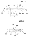
- the peaks 4A, 9A and valleys 4B, 9B of the engagement formations 4, 9 do in this building structure 20 have a height A that is important to the strength of the joined together building structure 20 and also to the compressive forces that arise in the building elements 1, 2 when they are pulled towards each other.
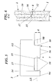
- outer 12, 14 and inner 13, 15 end surfaces of the alternating peaks 4A, 9A and valleys 4B, 9B of the respective first and second engagement formations 4, 9 are provided at a mutual distance A. The importance of the size of this distance A will be discussed below, with specific reference to Figs. 7 and 8 .
- this distance may generally be said to lie between approximately 5 and 80 % of the length LE of the respective building element in a direction transversal to the joint 8, preferably between approximately ca 20 and 50 % of this length.
- the measure A is normally chosen so as to not be larger than for the joint 8 to become equally strong with the building elements 1, 2 in themselves.
- the first and second engagement formations 4 and 9, respectively, of the building structure 20 have peaks 4A, 9A and valleys 4B, 9B that have outwardly generally converging and diverging, respectively, side surfaces 5, 10.
- peaks and valleys respectively, having fundamentally straight side surfaces, with a certain allowance to facilitate the joining together thereof, or even to design the peaks and valleys, respectively, having curved and wavy, respectively, profiles (not illustrated).
- a number of tension elements 18 are used in the building structure 20.
- the tension elements 18 each consist of an at least partially threaded tension bar 18.
- the tension bars 18 are received with clearance through aligned holes 19 in adjoining building elements 1, 2.
- nuts 18A are used to clamp the separate, adjoining building elements 1, 2 against each other by means of the tension bars 18 and with a tensioning force F1.
- the number of tension bars 18 used for the clamping may vary depending upon the circumstances at the specific application but is preferably chosen equal to or smaller than the number of peaks 4A, 9A and valleys 4B, 9B, respectively, in the engagement formations 4, 9 of the building elements 1, 2.
- each of the separate, adjoining building elements 1, 2 of the building structure 20 are in conjunction with the joint 8 provided with a number of transverse force supports 16, 17 that are separated in a general longitudinal direction LS of the joint 8.
- the transverse force supports 16, 17 are here made having the form of a groove 17 in the valleys 4B and 9B, respectively, of the first and second building elements 1, 2 and in the form of a protruding tongue 16 in the peaks 4A and 9A, respectively, of the first and second building elements 1, 2.
- transverse force supports 16, 17 that are employed at the building elements 1, 2 may also be varied in dependence upon the circumstances by the specific application, but basically one pair of a groove/tongue is provided for each peak and valley of the engagement formations that are combined in a joined condition.
- a tongue 16 and a groove 17 are only provided in the surfaces that lie perpendicular to the bending moment MB ( Fig. 7 ) but for specific applications with special circumstances it is also possible to provide them also in other surfaces of the joint 8.
- a joint 8 formed between adjoining building elements 1, 2 in a building structure 20 according to the new technology is thus characterized by a first engagement formation 4 with alternating peaks 4A and valleys 4B at a portion 3 of an outer circumference O1 of a first building element 1 and a second engagement formation 9 with alternating peaks 9A and valleys 9B at a portion 7 of an outer circumference 02 of a second building element 2.
- the respective first and second engagement formations of the first and second building elements thereby have a mutually fitting complementary shape.
- each of the adjoining building elements 1, 2 are preferably fitted with a number of transverse force supports 16, 17 that are separated in a general longitudinal direction LS of the joint 8 and that stabilize the joint 8 and take up transversal forces between the building elements.
- the described technology finally includes also a method of forming a building structure 20 as specified above, whereby a number of adjoining building elements 1, 2 are joined together so that a joint 8 is formed between the building elements.
- a uniting force F1 is applied by tension elements 18 to the building elements that are joined together at the joint.
- a first building element 1 is at least at a portion 3 of its outer circumference O1 made/fitted with a first engagement formation 4 that is formed having alternating peaks 4A and valleys 4B.
- a second building element 2 is at least at a portion 7 of its outer circumference 02 made/fitted with a second engagement formation 9 that is likewise formed having alternating peaks 9A and valleys 9B.
- the respective first and second engagement formations of the first and second building elements are thereby formed having mutually fitting complementary shape and the first and second engagement formations are brought together and are tensioned together by the tension elements 18 to form the joint 8.
- the first and second engagement formations 4, 9 are each formed with outer 12, 14 and inner 13 15, respectively, end surfaces at their peaks 4A, 9A and valleys 4B, 9B that are provided at a mutual distance A of between approximately 5 and 80 %, preferably between approximately 20 and 50 %, of the length LE of the respective building element in a direction transversal to the joint 8.
- These peaks 4A, 9A and valleys 4B, 9B of the first and second engagement formations 4 and 9, respectively, are formed having straight or alternatively outwardly generally converging or diverging side surfaces 5 and 10, respectively.
- At least one partially threaded tension bar 18 is extended with clearance through holes 19 formed in adjoining building elements 1, 2 and is tensioned with tensioning force F1 against each of these building elements.
- a number of transverse force supports 16, 17 that are separated in a general longitudinal direction LS of the joint 8.
- a divided concrete slab according to this new technology may in particular be prefabricated and may very quickly and economically be transported to and installed at a building site.
- the building structure according to this technology may also be dismounted and reinstalled again in another place. It is also possible to easily implement it as a divided slab with cast-in drains, water pipes, and floor heating, which is an important and large market.
- the delivery time from storage may probably be reduced to a week. As mentioned, this is a quite significantly shorter delivery time than for a concrete slab cast on-site.
- An installation time of approximately an hour may be calculated with, which all in all gives a very advantageous total time.
- Such a divided concrete slab is also very moment resisting and the strength may be maintained comparable to that of a concrete slab that is cast in one piece. Whereas it is very expensive, if at all possible, to transport a complete concrete slab the moment resisting, divided concrete slab makes normal economical transports possible. Further advantages are that the divided concrete slab according to the new technology may be prefabricated, which leads to lower price and more uniform quality, and that it may even be transported together with a building kit or the like.
Landscapes
- Engineering & Computer Science (AREA)
- Architecture (AREA)
- Civil Engineering (AREA)
- Structural Engineering (AREA)
- Physics & Mathematics (AREA)
- Electromagnetism (AREA)
- Life Sciences & Earth Sciences (AREA)
- General Life Sciences & Earth Sciences (AREA)
- Mining & Mineral Resources (AREA)
- Paleontology (AREA)
- General Engineering & Computer Science (AREA)
- Joining Of Building Structures In Genera (AREA)
Applications Claiming Priority (1)
| Application Number | Priority Date | Filing Date | Title |
|---|---|---|---|
| SE1450412A SE539783C2 (sv) | 2014-04-04 | 2014-04-04 | Av byggelement bildad byggkonstruktion, metod för att bilda en byggkonstruktion samt en skarv |
Publications (2)
| Publication Number | Publication Date |
|---|---|
| EP2927381A1 true EP2927381A1 (fr) | 2015-10-07 |
| EP2927381B1 EP2927381B1 (fr) | 2018-05-16 |
Family
ID=52726980
Family Applications (1)
| Application Number | Title | Priority Date | Filing Date |
|---|---|---|---|
| EP15159450.4A Not-in-force EP2927381B1 (fr) | 2014-04-04 | 2015-03-17 | Structure de bâtiment formée d'éléments de construction |
Country Status (2)
| Country | Link |
|---|---|
| EP (1) | EP2927381B1 (fr) |
| SE (1) | SE539783C2 (fr) |
Citations (4)
| Publication number | Priority date | Publication date | Assignee | Title |
|---|---|---|---|---|
| US2241169A (en) * | 1937-12-08 | 1941-05-06 | Yokes Otto | Building construction |
| US20050072115A1 (en) * | 2003-09-19 | 2005-04-07 | Chappell Ralph Louis | Preformed portable slab for use as a foundation or splash pad for industrial equipment |
| US20100154332A1 (en) * | 2008-12-23 | 2010-06-24 | Chevron U.S.A. Inc. | Base mat assembly and method of constructing the same |
| WO2011034603A2 (fr) * | 2009-09-16 | 2011-03-24 | Pre-Con Products, Ltd. | Système et procédé de fondation modulaire |
-
2014
- 2014-04-04 SE SE1450412A patent/SE539783C2/sv not_active IP Right Cessation
-
2015
- 2015-03-17 EP EP15159450.4A patent/EP2927381B1/fr not_active Not-in-force
Patent Citations (4)
| Publication number | Priority date | Publication date | Assignee | Title |
|---|---|---|---|---|
| US2241169A (en) * | 1937-12-08 | 1941-05-06 | Yokes Otto | Building construction |
| US20050072115A1 (en) * | 2003-09-19 | 2005-04-07 | Chappell Ralph Louis | Preformed portable slab for use as a foundation or splash pad for industrial equipment |
| US20100154332A1 (en) * | 2008-12-23 | 2010-06-24 | Chevron U.S.A. Inc. | Base mat assembly and method of constructing the same |
| WO2011034603A2 (fr) * | 2009-09-16 | 2011-03-24 | Pre-Con Products, Ltd. | Système et procédé de fondation modulaire |
Also Published As
| Publication number | Publication date |
|---|---|
| SE539783C2 (sv) | 2017-11-28 |
| SE1450412A1 (sv) | 2015-10-05 |
| EP2927381B1 (fr) | 2018-05-16 |
Similar Documents
| Publication | Publication Date | Title |
|---|---|---|
| AU659163B2 (en) | Sheet metal structural member, construction panel and method of construction | |
| CA2697085C (fr) | Coffrage | |
| US6347904B1 (en) | Fly clamp for reinforcing bars in concrete construction | |
| CN104032839B (zh) | 摩擦型阻尼器装配式框架节点的连接结构及其施工方法 | |
| US9234350B1 (en) | System and method of constructing a composite assembly | |
| US9957686B2 (en) | Modular foundation system and method | |
| US9297161B2 (en) | Roof member anti-torsion bracket device and method of use | |
| CN104405139B (zh) | 石砌墙体加固方法 | |
| WO2014159417A2 (fr) | Dalles de chaussée dotées de chevilles coulissantes | |
| BR112016017131B1 (pt) | Estrutura de aço de peso leve tridimensional formada por vigas duplas contínuas de duas vias | |
| CN107237402A (zh) | 一种低损伤自复位装配式混凝土双向框架梁柱节点 | |
| CN107700667A (zh) | 一种预制楼板与钢梁下翼缘连接节点 | |
| CN105155690A (zh) | 一种预制板连接节点和拼合预制板的施工方法 | |
| CN116446305B (zh) | 钢筋混凝土箱梁翼缘板拼宽加固方法 | |
| EP2927381B1 (fr) | Structure de bâtiment formée d'éléments de construction | |
| CN108026727A (zh) | 夹持件 | |
| US3683581A (en) | Prefabricated frame | |
| CN105275091A (zh) | 一种预制板与预制梁的连接节点及其施工方法 | |
| RU2358068C1 (ru) | Узловое соединение пересекающихся стержней | |
| CN205189129U (zh) | 一种特定预埋滑槽承载组件 | |
| CN206299126U (zh) | 一种装配式板柱结构楼板及楼板单元构件 | |
| JP4566138B2 (ja) | ソイルセメント複合杭 | |
| DE202012001342U1 (de) | Transportanker für Doppelwände | |
| JP4884200B2 (ja) | 既設柱の耐震補強構造及び該耐震補強構造の施工方法 | |
| WO2014158109A1 (fr) | Innovation destinée à une armature d'effort tranchant de poutres de couplage de murs de contreventement couplés |
Legal Events
| Date | Code | Title | Description |
|---|---|---|---|
| PUAI | Public reference made under article 153(3) epc to a published international application that has entered the european phase |
Free format text: ORIGINAL CODE: 0009012 |
|
| AK | Designated contracting states |
Kind code of ref document: A1 Designated state(s): AL AT BE BG CH CY CZ DE DK EE ES FI FR GB GR HR HU IE IS IT LI LT LU LV MC MK MT NL NO PL PT RO RS SE SI SK SM TR |
|
| AX | Request for extension of the european patent |
Extension state: BA ME |
|
| 17P | Request for examination filed |
Effective date: 20160407 |
|
| RBV | Designated contracting states (corrected) |
Designated state(s): AL AT BE BG CH CY CZ DE DK EE ES FI FR GB GR HR HU IE IS IT LI LT LU LV MC MK MT NL NO PL PT RO RS SE SI SK SM TR |
|
| STAA | Information on the status of an ep patent application or granted ep patent |
Free format text: STATUS: EXAMINATION IS IN PROGRESS |
|
| 17Q | First examination report despatched |
Effective date: 20170404 |
|
| GRAP | Despatch of communication of intention to grant a patent |
Free format text: ORIGINAL CODE: EPIDOSNIGR1 |
|
| STAA | Information on the status of an ep patent application or granted ep patent |
Free format text: STATUS: GRANT OF PATENT IS INTENDED |
|
| INTG | Intention to grant announced |
Effective date: 20171204 |
|
| GRAS | Grant fee paid |
Free format text: ORIGINAL CODE: EPIDOSNIGR3 |
|
| GRAA | (expected) grant |
Free format text: ORIGINAL CODE: 0009210 |
|
| STAA | Information on the status of an ep patent application or granted ep patent |
Free format text: STATUS: THE PATENT HAS BEEN GRANTED |
|
| AK | Designated contracting states |
Kind code of ref document: B1 Designated state(s): AL AT BE BG CH CY CZ DE DK EE ES FI FR GB GR HR HU IE IS IT LI LT LU LV MC MK MT NL NO PL PT RO RS SE SI SK SM TR |
|
| REG | Reference to a national code |
Ref country code: GB Ref legal event code: FG4D |
|
| REG | Reference to a national code |
Ref country code: CH Ref legal event code: EP |
|
| REG | Reference to a national code |
Ref country code: IE Ref legal event code: FG4D |
|
| REG | Reference to a national code |
Ref country code: DE Ref legal event code: R096 Ref document number: 602015011076 Country of ref document: DE |
|
| REG | Reference to a national code |
Ref country code: AT Ref legal event code: REF Ref document number: 999699 Country of ref document: AT Kind code of ref document: T Effective date: 20180615 |
|
| REG | Reference to a national code |
Ref country code: NL Ref legal event code: MP Effective date: 20180516 |
|
| REG | Reference to a national code |
Ref country code: LT Ref legal event code: MG4D |
|
| PG25 | Lapsed in a contracting state [announced via postgrant information from national office to epo] |
Ref country code: BG Free format text: LAPSE BECAUSE OF FAILURE TO SUBMIT A TRANSLATION OF THE DESCRIPTION OR TO PAY THE FEE WITHIN THE PRESCRIBED TIME-LIMIT Effective date: 20180816 Ref country code: NO Free format text: LAPSE BECAUSE OF FAILURE TO SUBMIT A TRANSLATION OF THE DESCRIPTION OR TO PAY THE FEE WITHIN THE PRESCRIBED TIME-LIMIT Effective date: 20180816 Ref country code: SE Free format text: LAPSE BECAUSE OF FAILURE TO SUBMIT A TRANSLATION OF THE DESCRIPTION OR TO PAY THE FEE WITHIN THE PRESCRIBED TIME-LIMIT Effective date: 20180516 Ref country code: ES Free format text: LAPSE BECAUSE OF FAILURE TO SUBMIT A TRANSLATION OF THE DESCRIPTION OR TO PAY THE FEE WITHIN THE PRESCRIBED TIME-LIMIT Effective date: 20180516 Ref country code: LT Free format text: LAPSE BECAUSE OF FAILURE TO SUBMIT A TRANSLATION OF THE DESCRIPTION OR TO PAY THE FEE WITHIN THE PRESCRIBED TIME-LIMIT Effective date: 20180516 |
|
| PG25 | Lapsed in a contracting state [announced via postgrant information from national office to epo] |
Ref country code: NL Free format text: LAPSE BECAUSE OF FAILURE TO SUBMIT A TRANSLATION OF THE DESCRIPTION OR TO PAY THE FEE WITHIN THE PRESCRIBED TIME-LIMIT Effective date: 20180516 Ref country code: HR Free format text: LAPSE BECAUSE OF FAILURE TO SUBMIT A TRANSLATION OF THE DESCRIPTION OR TO PAY THE FEE WITHIN THE PRESCRIBED TIME-LIMIT Effective date: 20180516 Ref country code: GR Free format text: LAPSE BECAUSE OF FAILURE TO SUBMIT A TRANSLATION OF THE DESCRIPTION OR TO PAY THE FEE WITHIN THE PRESCRIBED TIME-LIMIT Effective date: 20180817 Ref country code: LV Free format text: LAPSE BECAUSE OF FAILURE TO SUBMIT A TRANSLATION OF THE DESCRIPTION OR TO PAY THE FEE WITHIN THE PRESCRIBED TIME-LIMIT Effective date: 20180516 Ref country code: RS Free format text: LAPSE BECAUSE OF FAILURE TO SUBMIT A TRANSLATION OF THE DESCRIPTION OR TO PAY THE FEE WITHIN THE PRESCRIBED TIME-LIMIT Effective date: 20180516 |
|
| REG | Reference to a national code |
Ref country code: AT Ref legal event code: MK05 Ref document number: 999699 Country of ref document: AT Kind code of ref document: T Effective date: 20180516 |
|
| PG25 | Lapsed in a contracting state [announced via postgrant information from national office to epo] |
Ref country code: DK Free format text: LAPSE BECAUSE OF FAILURE TO SUBMIT A TRANSLATION OF THE DESCRIPTION OR TO PAY THE FEE WITHIN THE PRESCRIBED TIME-LIMIT Effective date: 20180516 Ref country code: EE Free format text: LAPSE BECAUSE OF FAILURE TO SUBMIT A TRANSLATION OF THE DESCRIPTION OR TO PAY THE FEE WITHIN THE PRESCRIBED TIME-LIMIT Effective date: 20180516 Ref country code: CZ Free format text: LAPSE BECAUSE OF FAILURE TO SUBMIT A TRANSLATION OF THE DESCRIPTION OR TO PAY THE FEE WITHIN THE PRESCRIBED TIME-LIMIT Effective date: 20180516 Ref country code: AT Free format text: LAPSE BECAUSE OF FAILURE TO SUBMIT A TRANSLATION OF THE DESCRIPTION OR TO PAY THE FEE WITHIN THE PRESCRIBED TIME-LIMIT Effective date: 20180516 Ref country code: SK Free format text: LAPSE BECAUSE OF FAILURE TO SUBMIT A TRANSLATION OF THE DESCRIPTION OR TO PAY THE FEE WITHIN THE PRESCRIBED TIME-LIMIT Effective date: 20180516 Ref country code: RO Free format text: LAPSE BECAUSE OF FAILURE TO SUBMIT A TRANSLATION OF THE DESCRIPTION OR TO PAY THE FEE WITHIN THE PRESCRIBED TIME-LIMIT Effective date: 20180516 Ref country code: PL Free format text: LAPSE BECAUSE OF FAILURE TO SUBMIT A TRANSLATION OF THE DESCRIPTION OR TO PAY THE FEE WITHIN THE PRESCRIBED TIME-LIMIT Effective date: 20180516 |
|
| REG | Reference to a national code |
Ref country code: DE Ref legal event code: R097 Ref document number: 602015011076 Country of ref document: DE |
|
| PG25 | Lapsed in a contracting state [announced via postgrant information from national office to epo] |
Ref country code: IT Free format text: LAPSE BECAUSE OF FAILURE TO SUBMIT A TRANSLATION OF THE DESCRIPTION OR TO PAY THE FEE WITHIN THE PRESCRIBED TIME-LIMIT Effective date: 20180516 Ref country code: SM Free format text: LAPSE BECAUSE OF FAILURE TO SUBMIT A TRANSLATION OF THE DESCRIPTION OR TO PAY THE FEE WITHIN THE PRESCRIBED TIME-LIMIT Effective date: 20180516 |
|
| PLBE | No opposition filed within time limit |
Free format text: ORIGINAL CODE: 0009261 |
|
| STAA | Information on the status of an ep patent application or granted ep patent |
Free format text: STATUS: NO OPPOSITION FILED WITHIN TIME LIMIT |
|
| 26N | No opposition filed |
Effective date: 20190219 |
|
| PG25 | Lapsed in a contracting state [announced via postgrant information from national office to epo] |
Ref country code: SI Free format text: LAPSE BECAUSE OF FAILURE TO SUBMIT A TRANSLATION OF THE DESCRIPTION OR TO PAY THE FEE WITHIN THE PRESCRIBED TIME-LIMIT Effective date: 20180516 |
|
| REG | Reference to a national code |
Ref country code: DE Ref legal event code: R119 Ref document number: 602015011076 Country of ref document: DE |
|
| PG25 | Lapsed in a contracting state [announced via postgrant information from national office to epo] |
Ref country code: MC Free format text: LAPSE BECAUSE OF FAILURE TO SUBMIT A TRANSLATION OF THE DESCRIPTION OR TO PAY THE FEE WITHIN THE PRESCRIBED TIME-LIMIT Effective date: 20180516 |
|
| REG | Reference to a national code |
Ref country code: CH Ref legal event code: PL |
|
| GBPC | Gb: european patent ceased through non-payment of renewal fee |
Effective date: 20190317 |
|
| PG25 | Lapsed in a contracting state [announced via postgrant information from national office to epo] |
Ref country code: LU Free format text: LAPSE BECAUSE OF NON-PAYMENT OF DUE FEES Effective date: 20190317 Ref country code: AL Free format text: LAPSE BECAUSE OF FAILURE TO SUBMIT A TRANSLATION OF THE DESCRIPTION OR TO PAY THE FEE WITHIN THE PRESCRIBED TIME-LIMIT Effective date: 20180516 |
|
| REG | Reference to a national code |
Ref country code: BE Ref legal event code: MM Effective date: 20190331 |
|
| PG25 | Lapsed in a contracting state [announced via postgrant information from national office to epo] |
Ref country code: LI Free format text: LAPSE BECAUSE OF NON-PAYMENT OF DUE FEES Effective date: 20190331 Ref country code: DE Free format text: LAPSE BECAUSE OF NON-PAYMENT OF DUE FEES Effective date: 20191001 Ref country code: IE Free format text: LAPSE BECAUSE OF NON-PAYMENT OF DUE FEES Effective date: 20190317 Ref country code: CH Free format text: LAPSE BECAUSE OF NON-PAYMENT OF DUE FEES Effective date: 20190331 Ref country code: GB Free format text: LAPSE BECAUSE OF NON-PAYMENT OF DUE FEES Effective date: 20190317 |
|
| PG25 | Lapsed in a contracting state [announced via postgrant information from national office to epo] |
Ref country code: FR Free format text: LAPSE BECAUSE OF NON-PAYMENT OF DUE FEES Effective date: 20190331 Ref country code: BE Free format text: LAPSE BECAUSE OF NON-PAYMENT OF DUE FEES Effective date: 20190331 |
|
| PG25 | Lapsed in a contracting state [announced via postgrant information from national office to epo] |
Ref country code: TR Free format text: LAPSE BECAUSE OF FAILURE TO SUBMIT A TRANSLATION OF THE DESCRIPTION OR TO PAY THE FEE WITHIN THE PRESCRIBED TIME-LIMIT Effective date: 20180516 |
|
| PGFP | Annual fee paid to national office [announced via postgrant information from national office to epo] |
Ref country code: FI Payment date: 20200316 Year of fee payment: 6 |
|
| PG25 | Lapsed in a contracting state [announced via postgrant information from national office to epo] |
Ref country code: PT Free format text: LAPSE BECAUSE OF FAILURE TO SUBMIT A TRANSLATION OF THE DESCRIPTION OR TO PAY THE FEE WITHIN THE PRESCRIBED TIME-LIMIT Effective date: 20180917 Ref country code: MT Free format text: LAPSE BECAUSE OF NON-PAYMENT OF DUE FEES Effective date: 20190317 |
|
| PG25 | Lapsed in a contracting state [announced via postgrant information from national office to epo] |
Ref country code: CY Free format text: LAPSE BECAUSE OF FAILURE TO SUBMIT A TRANSLATION OF THE DESCRIPTION OR TO PAY THE FEE WITHIN THE PRESCRIBED TIME-LIMIT Effective date: 20180516 |
|
| PG25 | Lapsed in a contracting state [announced via postgrant information from national office to epo] |
Ref country code: IS Free format text: LAPSE BECAUSE OF FAILURE TO SUBMIT A TRANSLATION OF THE DESCRIPTION OR TO PAY THE FEE WITHIN THE PRESCRIBED TIME-LIMIT Effective date: 20180916 |
|
| PG25 | Lapsed in a contracting state [announced via postgrant information from national office to epo] |
Ref country code: HU Free format text: LAPSE BECAUSE OF FAILURE TO SUBMIT A TRANSLATION OF THE DESCRIPTION OR TO PAY THE FEE WITHIN THE PRESCRIBED TIME-LIMIT; INVALID AB INITIO Effective date: 20150317 |
|
| REG | Reference to a national code |
Ref country code: FI Ref legal event code: MAE |
|
| PG25 | Lapsed in a contracting state [announced via postgrant information from national office to epo] |
Ref country code: FI Free format text: LAPSE BECAUSE OF NON-PAYMENT OF DUE FEES Effective date: 20210317 |
|
| PG25 | Lapsed in a contracting state [announced via postgrant information from national office to epo] |
Ref country code: MK Free format text: LAPSE BECAUSE OF FAILURE TO SUBMIT A TRANSLATION OF THE DESCRIPTION OR TO PAY THE FEE WITHIN THE PRESCRIBED TIME-LIMIT Effective date: 20180516 |