EP2930085B1 - Dispositif de direction - Google Patents
Dispositif de direction Download PDFInfo
- Publication number
- EP2930085B1 EP2930085B1 EP15161185.2A EP15161185A EP2930085B1 EP 2930085 B1 EP2930085 B1 EP 2930085B1 EP 15161185 A EP15161185 A EP 15161185A EP 2930085 B1 EP2930085 B1 EP 2930085B1
- Authority
- EP
- European Patent Office
- Prior art keywords
- case
- blocking piece
- valve element
- hole
- steering device
- Prior art date
- Legal status (The legal status is an assumption and is not a legal conclusion. Google has not performed a legal analysis and makes no representation as to the accuracy of the status listed.)
- Not-in-force
Links
- 230000000903 blocking effect Effects 0.000 claims description 66
- 230000002093 peripheral effect Effects 0.000 claims description 35
- 239000003638 chemical reducing agent Substances 0.000 claims description 20
- XLYOFNOQVPJJNP-UHFFFAOYSA-N water Substances O XLYOFNOQVPJJNP-UHFFFAOYSA-N 0.000 description 53
- 230000007246 mechanism Effects 0.000 description 10
- ORQBXQOJMQIAOY-UHFFFAOYSA-N nobelium Chemical compound [No] ORQBXQOJMQIAOY-UHFFFAOYSA-N 0.000 description 9
- 238000005096 rolling process Methods 0.000 description 4
- 230000000694 effects Effects 0.000 description 2
- 230000004048 modification Effects 0.000 description 2
- 238000012986 modification Methods 0.000 description 2
- 230000008859 change Effects 0.000 description 1
- 239000011347 resin Substances 0.000 description 1
- 229920005989 resin Polymers 0.000 description 1
- 239000004575 stone Substances 0.000 description 1
Images


Classifications
-
- B—PERFORMING OPERATIONS; TRANSPORTING
- B62—LAND VEHICLES FOR TRAVELLING OTHERWISE THAN ON RAILS
- B62D—MOTOR VEHICLES; TRAILERS
- B62D5/00—Power-assisted or power-driven steering
- B62D5/04—Power-assisted or power-driven steering electrical, e.g. using an electric servo-motor connected to, or forming part of, the steering gear
- B62D5/0421—Electric motor acting on or near steering gear
- B62D5/0424—Electric motor acting on or near steering gear the axes of motor and final driven element of steering gear, e.g. rack, being parallel
-
- F—MECHANICAL ENGINEERING; LIGHTING; HEATING; WEAPONS; BLASTING
- F16—ENGINEERING ELEMENTS AND UNITS; GENERAL MEASURES FOR PRODUCING AND MAINTAINING EFFECTIVE FUNCTIONING OF MACHINES OR INSTALLATIONS; THERMAL INSULATION IN GENERAL
- F16K—VALVES; TAPS; COCKS; ACTUATING-FLOATS; DEVICES FOR VENTING OR AERATING
- F16K15/00—Check valves
- F16K15/14—Check valves with flexible valve members
- F16K15/144—Check valves with flexible valve members the closure elements being fixed along all or a part of their periphery
-
- F—MECHANICAL ENGINEERING; LIGHTING; HEATING; WEAPONS; BLASTING
- F16—ENGINEERING ELEMENTS AND UNITS; GENERAL MEASURES FOR PRODUCING AND MAINTAINING EFFECTIVE FUNCTIONING OF MACHINES OR INSTALLATIONS; THERMAL INSULATION IN GENERAL
- F16K—VALVES; TAPS; COCKS; ACTUATING-FLOATS; DEVICES FOR VENTING OR AERATING
- F16K15/00—Check valves
- F16K15/14—Check valves with flexible valve members
- F16K15/148—Check valves with flexible valve members the closure elements being fixed in their centre
-
- F—MECHANICAL ENGINEERING; LIGHTING; HEATING; WEAPONS; BLASTING
- F16—ENGINEERING ELEMENTS AND UNITS; GENERAL MEASURES FOR PRODUCING AND MAINTAINING EFFECTIVE FUNCTIONING OF MACHINES OR INSTALLATIONS; THERMAL INSULATION IN GENERAL
- F16K—VALVES; TAPS; COCKS; ACTUATING-FLOATS; DEVICES FOR VENTING OR AERATING
- F16K15/00—Check valves
- F16K15/14—Check valves with flexible valve members
- F16K15/16—Check valves with flexible valve members with tongue-shaped laminae
Definitions
- the present invention relates to a steering device.
- a rack-parallel electric power steering device is known as one type of steering devices for vehicles.
- the rack-parallel electric power steering device includes a ball screw device attached to the outer periphery of a rack shaft, a motor with an output shaft disposed in parallel with the rack shaft, and a speed reducer that couples the output shaft of the motor and the ball screw device to each other.
- the periphery of the speed reducer is covered by a housing.
- the speed reducer when water enters the housing from the outside and the water resides in the housing, the speed reducer may be flooded with the water.
- the speed reducer When the water in the housing is frozen with the speed reducer flooded with water, operation of the speed reducer is hindered.
- a steering feel When operation of the rack shaft coupled to the speed reducer via the ball screw device is hindered, a steering feel may be deteriorated by a heavy steering operation or the like.
- a steering device in which a drain valve is provided at a bottom wall portion of a housing under a speed reducer in the vertical direction in order to discharge water having entered the housing.
- An example of such a drain valve is described in German Patent Application Publication No. 10 2009 039 832 .
- a drain valve 100 described in German Patent Application Publication No. 10 2009 039 832 includes a case body 101 in a bottomed cylindrical shape, and a valve element 102 housed inside the case body 101.
- the case body 101 is structured such that a second case 104 in a bottomed cylindrical shape is assembled to an end portion of a cylindrical first case 103.
- a cylindrical attachment portion 103a is formed at the center portion of an opening portion of the first case 103 on the second case 104 side.
- a valve seat 103b which is an annular projecting portion is formed at an end surface of the first case 103 on the second case 104 side.
- a discharge hole 104a that penetrates from the inside to the outside is formed in the bottom portion of the second case 104.
- the valve element 102 is a disc-shaped elastic member.
- a projecting portion 102a is formed at the center portion of the valve element 102.
- the projecting portion 102a engages with the attachment portion 103a of the first case 103 so that the valve element 102 is fixed with respect to the first case 103.
- the peripheral edge portion of the valve element 102 closely contacts the valve seat 103b of the first case 103.
- water having entered a housing (not illustrated) flows into the first case 103 through an opening portion 103c of the first case 103, and is discharged to the outside of the housing via the valve element 102 and the discharge hole 104a.
- the valve element 102 suppresses inflow of the water into the housing.
- An aspect of the present invention provides a steering device including: a steered shaft that moves in an axial direction on the basis of rotation of a steering shaft to steer steered wheels; a motor that applies an assist force to the steered shaft via a speed reducer; and a housing that covers a periphery of the speed reducer.
- a drain valve is provided at a bottom wall portion of the housing under the speed reducer in a vertical direction.
- the drain valve includes: a first case that opens into the housing and that has a bottomed cylindrical shape having a bottom portion in which a through hole is formed; a second case that is mounted to an outer peripheral portion of the bottom portion of the first case and that has a bottomed cylindrical shape having a bottom portion which is disposed with a gap from the bottom portion of the first case and in which a discharge hole is formed; and a valve element formed of an elastic member that closely contacts a bottom surface of the first case to block an opening portion of the through hole and that is held between the first case and the second case.
- water having entered the housing flows into the first case through the opening portion of the first case, and resides on the bottom portion of the first case.
- the water residing on the bottom portion of the first case contacts the valve element through the through hole formed in the bottom portion.
- the valve element is elastically deformed by the weight of the water. Consequently, water that resides inside the first case flows into the second case through a gap between the valve element and the bottom surface of the first case, and is discharged to the outside through the discharge hole of the second case.
- water having entered the housing can be discharged to the outside.
- valve element In the case where water outside the housing enters the second case via the discharge hole, meanwhile, the valve element is pressed in the direction in which the valve element closely contacts the bottom surface of the first case. The valve element is maintained in a state in which the valve element closely contacts the bottom surface of the first case. Therefore, entry of water into the housing from the outside of the housing via the drain valve can be suppressed.
- the valve element is held between the first case and the second case to be fixed. Therefore, it is not necessary to form the valve element and the cases with a structure for fixing the valve element as in the drain valve described in German Patent Application Publication No. 10 2009 039 832 . Therefore, the structure can be simplified.
- the valve element may include a blocking piece supported in a cantilever manner with a portion held between the first case and the second case, and a distal-end portion which is a free end of the blocking piece may block the opening portion of the through hole.
- the blocking piece is elastically deformable easily by the weight of water that contacts the blocking piece via the through hole of the first case. Therefore, water that resides inside the first case is discharged easily.
- the through hole may be formed in the bottom portion of the first case at a position offset from a center of the bottom portion; the valve element may be held between the first case and the second case at a portion of a peripheral edge portion of a bottom surface of the first case, which is the most distant from the through hole; and the blocking piece may be disposed to extend from the portion of the valve element held between the first case and the second case to the opening portion of the through hole.
- the overall length of the blocking piece can be increased, which makes the blocking piece elastically deformable more easily. Therefore, water that resides inside the first case is discharged more easily.
- the through hole may be a long hole that extends in a direction that is orthogonal to the extending direction of the blocking piece.
- the distal-end portion of the blocking piece and water that resides inside the first case contact each other over a large area, which causes the weight of the water to be applied to the distal-end portion of the blocking piece easily.
- the blocking piece is made elastically deformable easily, which causes water that resides inside the first case to be discharged more easily.
- a pair of the through holes may be formed in the bottom portion of the first case; and the valve element may include a blocking piece, a center portion of which is held between the first case and the second case at an intermediate position between respective opening portions of the through holes, and both end portions which are free ends of the blocking piece may block the respective opening portions of the through holes.
- the through holes may be long holes that extend in a direction that is orthogonal to the extending direction of the blocking piece.
- the both end portions of the blocking piece and water that resides inside the first case contact each other over a large area, which causes the weight of the water to be applied to the both end portions of the blocking piece easily.
- the blocking piece is made elastically deformable easily, which causes water that resides inside the first case to be discharged more easily.
- valve element may be held between an outer peripheral surface of the first case and an inner peripheral surface of the second case.
- a gap between the outer peripheral surface of the first case and the inner peripheral surface of the second case is sealed by the valve element. Therefore, inflow of water through the gap can be suppressed.
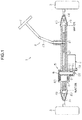
- the steering device according to the embodiment is a rack-parallel electric power steering device.
- a steering device 1 includes a steering mechanism 4 that steers steered wheels 3 on the basis of an operation of a steering wheel 2 performed by a driver, and an assist mechanism 5 that assists the driver in performing a steering operation.
- the steering mechanism 4 includes a steering shaft 40 that serves as a rotary shaft of the steering wheel 2, and a rack shaft 42 coupled to the lower end portion of the steering shaft 40 via a rack-and-pinion mechanism 41.
- the rack shaft 42 corresponds to the steered shaft.
- Tie rods 44 are rotatably connected to both ends of the rack shaft 42 via ball joints 43.
- the steered wheels 3 are coupled to the distal ends of the tie rods 44.
- the assist mechanism 5 is provided to the rack shaft 42.
- the assist mechanism 5 is composed of a ball screw device 6, a speed reducer 7, and a motor 8.
- the ball screw device 6, the speed reducer 7, and the rack shaft 42 are covered by a housing 9.
- the motor 8 is fixed to the outer wall of the housing 9 by a bolt 10 so that an output shaft 80 of the motor 8 is disposed in parallel with the rack shaft 42.
- the output shaft 80 of the motor 8 extends into the housing 9 through a through hole 11 formed in the housing 9.
- Bellows 45 are attached between both end portions of the housing 9 in the axial direction of the rack shaft 42 and the tie rods 44. The bellows 45 block opening portions at both ends of the housing 9 to suppress entry of foreign matter into the housing 9 from the outside.
- a spiral screw groove 46 is formed in the outer peripheral surface of the rack shaft 42.
- the ball screw device 6 includes a cylindrical nut 60 threadably engaged with the screw groove 46 via a plurality of balls 62 with the rack shaft 42 serving as a screw shaft.
- the nut 60 is supported by a bearing 63 so as to be rotatable with respect to the housing 9.
- a spiral screw groove 61 that faces the screw groove 46 of the rack shaft 42 is formed in the inner peripheral surface of the nut 60.
- a rolling passage R in which the balls 62 roll is formed by a spiral space surrounded by the screw groove 61 of the nut 60 and the screw groove 46 of the rack shaft 42.
- a circulation passage (not illustrated) that short-circuits two locations of the rolling passage R is formed in the nut 60.
- the balls 62 can endlessly circulate in the rolling passage R via the circulation passage in the nut 60.
- the speed reducer 7 includes a driving pulley 70 integrally attached to the output shaft 80 of the motor 8, a driven pulley 71 integrally attached to the outer periphery of the nut 60, and a belt 72 wound around the pulleys 70, 71.
- the driving pulley 70 rotates together with the output shaft 80 of the motor 8.
- the driving pulley 70 integrally rotates the driven pulley 71 and the nut 60 via the belt 72.
- the ball screw device 6 is driven on the basis of torque applied to the nut 60.
- the balls 62 receive a load from the nut 60 and the rack shaft 42 to endlessly circulate in the rolling passage R.
- torque applied to the nut 60 is transmitted to the rack shaft 42 to relatively move the rack shaft 42 with respect to the nut 60 in the axial direction.
- a force in the axial direction is applied to the rack shaft 42.
- the force in the axial direction applied to the rack shaft 42 serves as an assist force to assist a driver in performing a steering operation.
- An attachment hole 91 that penetrates from the inner surface to the outer surface is formed in a bottom wall portion 90 of the housing 9 under the speed reducer 7 in the vertical direction.
- the attachment hole 91 has female threads.
- a drain valve 20 is threadably attached to the attachment hole 91.
- FIG. 3 illustrates a sectional structure of the drain valve 20.
- the drain valve 20 includes a case body 21 formed in a bottomed cylindrical shape about an axis m, and a valve element 22 housed inside the case body 21.
- the case body 21 is formed by mounting a second case 24 in a bottomed cylindrical shape to the outer peripheral portion of a bottom portion 23a of a first case 23 in a bottomed cylindrical shape, and has a double-bottom structure.
- a flange portion 23c is formed at the outer peripheral portion of the bottom portion 23a of the first case 23.
- the flange portion 23c is formed so as to become smaller in outside diameter toward a bottom surface 23d of the first case 23. That is, the outer peripheral surface of the flange portion 23c is formed in a tapered shape.
- a notch 23e is formed at an end portion of the outer peripheral surface of the flange portion 23c on the opposite side of the first case 23 from the bottom surface 23d.
- a screw groove 23f is formed in the outer peripheral surface of a tubular portion of the first case 23.
- a ring groove 23g is formed between the screw groove 23f and the flange portion 23c.
- a through hole 23h that penetrates from the inner surface to the outer surface is formed in the bottom portion 23a of the first case 23 at a position offset from the center portion.
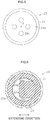
- FIG. 4 which illustrates a planar structure of the drain valve 20 seem from an opening portion 23b of the first case 23, the through hole 23h is formed in a long hole shape.
- the internal space of the first case 23 and the internal space of the second case 24 communicate with each other through the through hole 23h.
- an annular hook portion 24b that projects inward is formed at the opening portion of the second case 24.
- the hook portion 24b engages with the notch 23e of the flange portion 23c of the first case 23.
- the second case 24 is assembled to the first case 23 through the engagement structure.
- a bottom portion 24a of the second case 24 is disposed with a gap from the bottom portion 23a of the first case 23.
- An annular stepped portion 24c that projects toward the bottom surface 23d of the first case 23 is formed at the peripheral edge portion of the inner surface of the bottom portion 24a of the second case 24.
- Discharge holes 24d that penetrate from the inner surface to the outer surface are formed in the bottom portion 24a of the second case 24.
- FIG. 5 which illustrates the structure of the drain valve 20 seen from the bottom portion 24a side of the second case 24, the discharge holes 24d are disposed about the center axis m of the second case 24.
- the valve element 22 is disposed so as to closely contact the bottom surface 23d of the first case 23.
- the valve element 22 is an elastic member made of rubber, a resin, or the like.
- FIG. 6 which illustrates a cross-sectional structure taken along the line A-A of FIG. 3
- the valve element 22 includes an annular portion 22a and a blocking piece 22b formed to extend from the inner peripheral surface of the annular portion 22a.
- the annular portion 22a is disposed along the peripheral edge of the bottom surface 23d of the first case 23.
- the blocking piece 22b is formed to extend from a location on the inner peripheral surface of the annular portion 22a that is the most distant from the through hole 23h of the first case 23 to the through hole 23h, and blocks the opening portion of the through hole 23h. Consequently, the internal space of the first case 23 and the internal space of the second case 24 are separated by the blocking piece 22b.
- the annular portion 22a is held between the bottom surface 23d of the first case 23 and the stepped portion 24c of the second case 24. Consequently, the valve element 22 is fixed.
- a tubular portion 22c formed in a tubular shape about the axis m is formed at the outer edge of the annular portion 22a of the valve element 22.
- the tubular portion 22c is disposed along the outer peripheral surface of the flange portion 23c of the first case 23 and the notch 23e of the flange portion 23c, and held between the outer peripheral surface of the first case 23 and the inner peripheral surface of the second case 24.
- the drain valve 20 is fixed to the housing 9 with the screw groove 23f of the first case 23 threadably engaged with the attachment hole 91 of the housing 9.
- a seal ring 92 is fitted in the ring groove 23g of the first case 23.
- the seal ring 92 seals a gap between the outer peripheral surface of the first case 23 and the inner peripheral surface of the attachment hole 91 of the housing 9.
- the water residing on the bottom portion 23 a of the first case 23 contacts the blocking piece 22b of the valve element 22 through the through hole 23h formed in the bottom portion 23a. Then, when a certain amount of water or more resides on the bottom portion 23a of the first case 23, the blocking piece 22b of the valve element 22 is elastically deformed by the weight of the water as illustrated in FIG. 8 . Consequently, water inside the first case 23 flows into the second case 24 through a gap between the blocking piece 22b of the valve element 22 and the bottom surface 23d of the first case 23, and is discharged to the outside of the housing 9 through the discharge holes 24d of the second case 24. Thus, water having entered the housing 9 can be discharged to the outside.
- the blocking piece 22b of the valve element 22 is pressed in the direction in which the blocking piece 22b closely contacts the bottom surface 23d of the first case 23.
- the blocking piece 22b of the valve element 22 is maintained in a state in which the blocking piece 22b closely contacts the bottom surface 23d of the first case 23. Therefore, entry of water into the housing 9 from the outside of the housing 9 via the drain valve 20 can be suppressed.
Landscapes
- Engineering & Computer Science (AREA)
- Mechanical Engineering (AREA)
- General Engineering & Computer Science (AREA)
- Chemical & Material Sciences (AREA)
- Combustion & Propulsion (AREA)
- Transportation (AREA)
- Power Steering Mechanism (AREA)
- Valve Housings (AREA)
- Devices For Conveying Motion By Means Of Endless Flexible Members (AREA)
- General Details Of Gearings (AREA)
Claims (7)
- Dispositif de direction comprenant :un arbre directeur qui se déplace dans une direction axiale sur la base de la rotation d'un arbre de direction (40) pour diriger des roues directrices (3) ;un moteur (8) qui applique une force d'assistance sur l'arbre directeur via un réducteur de vitesse (7) ; etun logement (9) qui recouvre une périphérie du réducteur de vitesse (7), dans lequel :une valve de drain (20) est prévue au niveau d'une partie de paroi inférieure du logement (9) sous le réducteur de vitesse (7) dans une direction verticale, etla valve de drain (20) comprend :un premier boîtier (23) qui s'ouvre dans le logement (9) et qui a une forme cylindrique à fond ayant une partie inférieure (23a) dans laquelle au moins un trou débouchant (23h) est formé ;un second boîtier (24) qui est monté sur une partie périphérique externe de la partie inférieure (23a) du premier boîtier (23) et qui a une forme cylindrique à fond ayant une partie inférieure (24a) qui est disposée avec un espace par rapport à la partie inférieure (23a) du premier boîtier (23) et dans lequel un trou de décharge (24d) est formé ; etun élément de valve (22) formé avec un élément élastique, caractérisé en ce que ledit élément de valve est en contact étroit avec une surface inférieure (23d) du premier boîtier (23) pour bloquer une partie d'ouverture du trou débouchant (23h) et qui est maintenu entre le premier boîtier (23) et le second boîtier (24), alors qu'une partie dudit élément de valve est maintenue entre le premier boîtier (23) et le second boîtier (24).
- Dispositif de direction selon la revendication 1, dans lequel :l'élément de valve (20) comprend une pièce de blocage (22b) supportée en porte-à-faux avec une partie maintenue entre le première boîtier (23) et le second boîtier (24), et une partie d'extrémité distale (22d) qui est une extrémité libre de la pièce de blocage (22b), bloque la partie d'ouverture du trou débouchant (23h).
- Dispositif de direction selon la revendication 2, dans lequel :le trou débouchant (23h) est formé dans la partie inférieure (23a) du premier boîtier (23) au niveau d'une partie décalée d'un centre de la partie inférieure (23a),l'élément de valve (22) est maintenu entre le premier boîtier (23) et le second boîtier (24) au niveau d'une partie d'une partie de bord périphérique d'une surface inférieure (23d) du premier boîtier (23), qui est la plus distante par rapport au trou débouchant (23h), etla pièce de blocage (22b) est disposée pour s'étendre à partir de la partie de l'élément de valve (22) maintenue entre le premier boîtier (23) et le second boîtier (24) jusqu'à la partie d'ouverture du trou débouchant (23h).
- Dispositif de direction selon la revendication 2 ou 3, dans lequel :lorsqu'une direction s'étendant de la partie de la pièce de blocage (22b) supportée en porte-à-faux jusqu'à la partie d'extrémité distale (22d) est définie comme étant une direction d'extension de la pièce de blocage (22b), le trou débouchant (23h) est un trou long qui s'étend dans une direction qui est orthogonale à la direction d'extension de la pièce de blocage (22b).
- Dispositif de direction selon la revendication 1, dans lequel :une paire de trous débouchants (23i, 23j) formée dans la partie inférieure (23a) du premier boîtier (23) ; etl'élément de valve (20) comprend une pièce de blocage (22b), dont une partie centrale est maintenue entre le premier boîtier (23) et le second boîtier (24) dans une position intermédiaire entre les parties d'ouverture respectives des trous débouchants (23h) et les deux parties d'extrémité (22f, 22g) qui sont des extrémités libres de la pièce de blocage (22b) bloquent les parties d'ouverture respectives des trous débouchants (23i, 23j).
- Dispositif de direction selon la revendication 5, dans lequel :lorsqu'une direction s'étendant d'une partie de la pièce de blocage (22b) maintenue entre le premier boîtier (23) et le second boîtier (24) jusqu'aux deux parties d'extrémité (22f, 22g) est définie comme étant une direction d'extension de la pièce de blocage (22b), les trous débouchants (23h) sont des trous longs qui s'étendent dans une direction qui est orthogonale à la direction d'extension de la pièce de blocage (22b).
- Dispositif de direction selon l'une quelconque des revendications 1 à 6, dans lequel :l'élément de valve (22) est maintenu entre une surface périphérique externe du premier boîtier (23) et une surface périphérique interne du second boîtier (24).
Applications Claiming Priority (1)
| Application Number | Priority Date | Filing Date | Title |
|---|---|---|---|
| JP2014078837A JP2015199414A (ja) | 2014-04-07 | 2014-04-07 | ステアリング装置 |
Publications (3)
| Publication Number | Publication Date |
|---|---|
| EP2930085A2 EP2930085A2 (fr) | 2015-10-14 |
| EP2930085A3 EP2930085A3 (fr) | 2016-05-18 |
| EP2930085B1 true EP2930085B1 (fr) | 2018-01-10 |
Family
ID=52784958
Family Applications (1)
| Application Number | Title | Priority Date | Filing Date |
|---|---|---|---|
| EP15161185.2A Not-in-force EP2930085B1 (fr) | 2014-04-07 | 2015-03-26 | Dispositif de direction |
Country Status (4)
| Country | Link |
|---|---|
| US (1) | US9428218B2 (fr) |
| EP (1) | EP2930085B1 (fr) |
| JP (1) | JP2015199414A (fr) |
| CN (1) | CN104973121B (fr) |
Families Citing this family (6)
| Publication number | Priority date | Publication date | Assignee | Title |
|---|---|---|---|---|
| JP2017177996A (ja) * | 2016-03-29 | 2017-10-05 | 株式会社ショーワ | 動力伝達機構及び操舵装置 |
| JP6769854B2 (ja) * | 2016-12-08 | 2020-10-14 | 株式会社ジェイテクト | ステアリング装置 |
| US10780912B2 (en) * | 2017-07-12 | 2020-09-22 | Jtekt Corporation | Steering device |
| US11228223B2 (en) | 2018-05-21 | 2022-01-18 | Steering Solutions Ip Holding Corporation | Electric power steering sealing valve system, a valve assembly arranged in the end cap |
| JP7331687B2 (ja) * | 2019-12-25 | 2023-08-23 | 株式会社ジェイテクト | 操舵装置 |
| DE102024209095A1 (de) * | 2024-09-23 | 2026-03-26 | Volkswagen Aktiengesellschaft | Lenksystem mit einem Lenkgehäuse und einem seitlichen Gehäusedeckel sowie Kraftfahrzeug mit einem solchen Lenksystem |
Family Cites Families (7)
| Publication number | Priority date | Publication date | Assignee | Title |
|---|---|---|---|---|
| DE102006006679A1 (de) | 2005-10-06 | 2007-04-12 | Zf Lenksysteme Gmbh | Vorrichtung zum Freigeben einer Öffnung in einem Gehäuseteil eines Lenkgetriebes |
| EP1984228B1 (fr) | 2006-02-14 | 2011-05-04 | ZF-Lenksysteme GmbH | Dispositif pour dégager une ouverture dans un élément de boîtier d'un mécanisme de direction |
| DE102009039832B3 (de) | 2009-09-03 | 2011-01-27 | Thyssenkrupp Presta Ag | Wasserablassventil mit Schirmmembran |
| JP5617524B2 (ja) * | 2010-10-22 | 2014-11-05 | 株式会社ジェイテクト | 油圧式パワーステアリング装置 |
| DE102011001591A1 (de) | 2011-03-28 | 2012-10-04 | Zf Lenksysteme Gmbh | Vorrichtung zum Freigeben einer Öffnung in einem Gehäuseteil eines Lenkgetriebes |
| JP5900147B2 (ja) * | 2012-05-16 | 2016-04-06 | 株式会社ジェイテクト | ステアリング装置 |
| JP6123407B2 (ja) * | 2013-03-26 | 2017-05-10 | 株式会社ジェイテクト | 電動パワーステアリング装置 |
-
2014
- 2014-04-07 JP JP2014078837A patent/JP2015199414A/ja active Pending
-
2015
- 2015-03-24 US US14/667,308 patent/US9428218B2/en not_active Expired - Fee Related
- 2015-03-26 EP EP15161185.2A patent/EP2930085B1/fr not_active Not-in-force
- 2015-03-31 CN CN201510146548.1A patent/CN104973121B/zh not_active Expired - Fee Related
Non-Patent Citations (1)
| Title |
|---|
| None * |
Also Published As
| Publication number | Publication date |
|---|---|
| US20150284019A1 (en) | 2015-10-08 |
| EP2930085A3 (fr) | 2016-05-18 |
| CN104973121A (zh) | 2015-10-14 |
| JP2015199414A (ja) | 2015-11-12 |
| CN104973121B (zh) | 2018-12-28 |
| EP2930085A2 (fr) | 2015-10-14 |
| US9428218B2 (en) | 2016-08-30 |
Similar Documents
| Publication | Publication Date | Title |
|---|---|---|
| EP2930085B1 (fr) | Dispositif de direction | |
| US9440673B2 (en) | Steering device | |
| EP2783943B1 (fr) | Système de direction fonctionnant à l'énergie électrique | |
| EP2664518B1 (fr) | Système de direction | |
| US9897148B2 (en) | Reducer of electric power-assisted steering apparatus | |
| EP3333046B1 (fr) | Appareil de direction | |
| KR20100137170A (ko) | 랙 구동식 전동 파워 스티어링 장치 | |
| CN107571910B (zh) | 齿条辅助型电动转向装置 | |
| US9744988B2 (en) | Electric power steering apparatus | |
| EP2942548B1 (fr) | Mécanisme de vis à billes et dispositif de direction | |
| EP2918477A1 (fr) | Dispositif de direction | |
| JP2015000594A (ja) | ステアリング装置 | |
| CN104943735B (zh) | 转向装置 | |
| KR101809774B1 (ko) | 랙구동형 동력 보조 조향장치 | |
| JP2018016193A (ja) | ステアリング装置 | |
| US11493117B2 (en) | Ball screw device | |
| KR101405738B1 (ko) | 랙구동형 동력 보조 조향장치 | |
| KR20120027624A (ko) | 랙구동형 동력 보조 조향장치 | |
| KR102660407B1 (ko) | 랙구동형 동력 보조 조향장치 | |
| JP2018095159A (ja) | ステアリング装置 | |
| KR101427474B1 (ko) | 랙구동형 동력 보조 조향장치 | |
| JP2016101792A (ja) | ステアリング装置 | |
| US12325474B2 (en) | Reducer for vehicle steering device | |
| JP2016120872A (ja) | ステアリング装置 | |
| JP2016097842A (ja) | ステアリング装置 |
Legal Events
| Date | Code | Title | Description |
|---|---|---|---|
| PUAI | Public reference made under article 153(3) epc to a published international application that has entered the european phase |
Free format text: ORIGINAL CODE: 0009012 |
|
| AK | Designated contracting states |
Kind code of ref document: A2 Designated state(s): AL AT BE BG CH CY CZ DE DK EE ES FI FR GB GR HR HU IE IS IT LI LT LU LV MC MK MT NL NO PL PT RO RS SE SI SK SM TR |
|
| AX | Request for extension of the european patent |
Extension state: BA ME |
|
| PUAL | Search report despatched |
Free format text: ORIGINAL CODE: 0009013 |
|
| AK | Designated contracting states |
Kind code of ref document: A3 Designated state(s): AL AT BE BG CH CY CZ DE DK EE ES FI FR GB GR HR HU IE IS IT LI LT LU LV MC MK MT NL NO PL PT RO RS SE SI SK SM TR |
|
| AX | Request for extension of the european patent |
Extension state: BA ME |
|
| RIC1 | Information provided on ipc code assigned before grant |
Ipc: B62D 5/04 20060101AFI20160412BHEP |
|
| 17P | Request for examination filed |
Effective date: 20161110 |
|
| RBV | Designated contracting states (corrected) |
Designated state(s): AL AT BE BG CH CY CZ DE DK EE ES FI FR GB GR HR HU IE IS IT LI LT LU LV MC MK MT NL NO PL PT RO RS SE SI SK SM TR |
|
| RIC1 | Information provided on ipc code assigned before grant |
Ipc: F16K 15/14 20060101ALI20170529BHEP Ipc: B62D 5/04 20060101AFI20170529BHEP Ipc: F16K 15/16 20060101ALI20170529BHEP |
|
| GRAP | Despatch of communication of intention to grant a patent |
Free format text: ORIGINAL CODE: EPIDOSNIGR1 |
|
| INTG | Intention to grant announced |
Effective date: 20170717 |
|
| GRAS | Grant fee paid |
Free format text: ORIGINAL CODE: EPIDOSNIGR3 |
|
| GRAA | (expected) grant |
Free format text: ORIGINAL CODE: 0009210 |
|
| AK | Designated contracting states |
Kind code of ref document: B1 Designated state(s): AL AT BE BG CH CY CZ DE DK EE ES FI FR GB GR HR HU IE IS IT LI LT LU LV MC MK MT NL NO PL PT RO RS SE SI SK SM TR |
|
| REG | Reference to a national code |
Ref country code: CH Ref legal event code: EP Ref country code: AT Ref legal event code: REF Ref document number: 962055 Country of ref document: AT Kind code of ref document: T Effective date: 20180115 |
|
| REG | Reference to a national code |
Ref country code: IE Ref legal event code: FG4D |
|
| REG | Reference to a national code |
Ref country code: DE Ref legal event code: R096 Ref document number: 602015007276 Country of ref document: DE |
|
| REG | Reference to a national code |
Ref country code: FR Ref legal event code: PLFP Year of fee payment: 4 |
|
| REG | Reference to a national code |
Ref country code: NL Ref legal event code: MP Effective date: 20180110 |
|
| REG | Reference to a national code |
Ref country code: AT Ref legal event code: MK05 Ref document number: 962055 Country of ref document: AT Kind code of ref document: T Effective date: 20180110 |
|
| PG25 | Lapsed in a contracting state [announced via postgrant information from national office to epo] |
Ref country code: NL Free format text: LAPSE BECAUSE OF FAILURE TO SUBMIT A TRANSLATION OF THE DESCRIPTION OR TO PAY THE FEE WITHIN THE PRESCRIBED TIME-LIMIT Effective date: 20180110 |
|
| PG25 | Lapsed in a contracting state [announced via postgrant information from national office to epo] |
Ref country code: FI Free format text: LAPSE BECAUSE OF FAILURE TO SUBMIT A TRANSLATION OF THE DESCRIPTION OR TO PAY THE FEE WITHIN THE PRESCRIBED TIME-LIMIT Effective date: 20180110 Ref country code: NO Free format text: LAPSE BECAUSE OF FAILURE TO SUBMIT A TRANSLATION OF THE DESCRIPTION OR TO PAY THE FEE WITHIN THE PRESCRIBED TIME-LIMIT Effective date: 20180410 Ref country code: CY Free format text: LAPSE BECAUSE OF FAILURE TO SUBMIT A TRANSLATION OF THE DESCRIPTION OR TO PAY THE FEE WITHIN THE PRESCRIBED TIME-LIMIT Effective date: 20180110 Ref country code: HR Free format text: LAPSE BECAUSE OF FAILURE TO SUBMIT A TRANSLATION OF THE DESCRIPTION OR TO PAY THE FEE WITHIN THE PRESCRIBED TIME-LIMIT Effective date: 20180110 Ref country code: LT Free format text: LAPSE BECAUSE OF FAILURE TO SUBMIT A TRANSLATION OF THE DESCRIPTION OR TO PAY THE FEE WITHIN THE PRESCRIBED TIME-LIMIT Effective date: 20180110 Ref country code: ES Free format text: LAPSE BECAUSE OF FAILURE TO SUBMIT A TRANSLATION OF THE DESCRIPTION OR TO PAY THE FEE WITHIN THE PRESCRIBED TIME-LIMIT Effective date: 20180110 |
|
| PG25 | Lapsed in a contracting state [announced via postgrant information from national office to epo] |
Ref country code: PL Free format text: LAPSE BECAUSE OF FAILURE TO SUBMIT A TRANSLATION OF THE DESCRIPTION OR TO PAY THE FEE WITHIN THE PRESCRIBED TIME-LIMIT Effective date: 20180110 Ref country code: GR Free format text: LAPSE BECAUSE OF FAILURE TO SUBMIT A TRANSLATION OF THE DESCRIPTION OR TO PAY THE FEE WITHIN THE PRESCRIBED TIME-LIMIT Effective date: 20180411 Ref country code: AT Free format text: LAPSE BECAUSE OF FAILURE TO SUBMIT A TRANSLATION OF THE DESCRIPTION OR TO PAY THE FEE WITHIN THE PRESCRIBED TIME-LIMIT Effective date: 20180110 Ref country code: SE Free format text: LAPSE BECAUSE OF FAILURE TO SUBMIT A TRANSLATION OF THE DESCRIPTION OR TO PAY THE FEE WITHIN THE PRESCRIBED TIME-LIMIT Effective date: 20180110 Ref country code: LV Free format text: LAPSE BECAUSE OF FAILURE TO SUBMIT A TRANSLATION OF THE DESCRIPTION OR TO PAY THE FEE WITHIN THE PRESCRIBED TIME-LIMIT Effective date: 20180110 Ref country code: IS Free format text: LAPSE BECAUSE OF FAILURE TO SUBMIT A TRANSLATION OF THE DESCRIPTION OR TO PAY THE FEE WITHIN THE PRESCRIBED TIME-LIMIT Effective date: 20180510 Ref country code: BG Free format text: LAPSE BECAUSE OF FAILURE TO SUBMIT A TRANSLATION OF THE DESCRIPTION OR TO PAY THE FEE WITHIN THE PRESCRIBED TIME-LIMIT Effective date: 20180410 Ref country code: RS Free format text: LAPSE BECAUSE OF FAILURE TO SUBMIT A TRANSLATION OF THE DESCRIPTION OR TO PAY THE FEE WITHIN THE PRESCRIBED TIME-LIMIT Effective date: 20180110 |
|
| REG | Reference to a national code |
Ref country code: DE Ref legal event code: R097 Ref document number: 602015007276 Country of ref document: DE |
|
| PG25 | Lapsed in a contracting state [announced via postgrant information from national office to epo] |
Ref country code: EE Free format text: LAPSE BECAUSE OF FAILURE TO SUBMIT A TRANSLATION OF THE DESCRIPTION OR TO PAY THE FEE WITHIN THE PRESCRIBED TIME-LIMIT Effective date: 20180110 Ref country code: RO Free format text: LAPSE BECAUSE OF FAILURE TO SUBMIT A TRANSLATION OF THE DESCRIPTION OR TO PAY THE FEE WITHIN THE PRESCRIBED TIME-LIMIT Effective date: 20180110 Ref country code: IT Free format text: LAPSE BECAUSE OF FAILURE TO SUBMIT A TRANSLATION OF THE DESCRIPTION OR TO PAY THE FEE WITHIN THE PRESCRIBED TIME-LIMIT Effective date: 20180110 Ref country code: AL Free format text: LAPSE BECAUSE OF FAILURE TO SUBMIT A TRANSLATION OF THE DESCRIPTION OR TO PAY THE FEE WITHIN THE PRESCRIBED TIME-LIMIT Effective date: 20180110 |
|
| REG | Reference to a national code |
Ref country code: CH Ref legal event code: PL |
|
| PLBE | No opposition filed within time limit |
Free format text: ORIGINAL CODE: 0009261 |
|
| STAA | Information on the status of an ep patent application or granted ep patent |
Free format text: STATUS: NO OPPOSITION FILED WITHIN TIME LIMIT |
|
| PG25 | Lapsed in a contracting state [announced via postgrant information from national office to epo] |
Ref country code: CZ Free format text: LAPSE BECAUSE OF FAILURE TO SUBMIT A TRANSLATION OF THE DESCRIPTION OR TO PAY THE FEE WITHIN THE PRESCRIBED TIME-LIMIT Effective date: 20180110 Ref country code: SK Free format text: LAPSE BECAUSE OF FAILURE TO SUBMIT A TRANSLATION OF THE DESCRIPTION OR TO PAY THE FEE WITHIN THE PRESCRIBED TIME-LIMIT Effective date: 20180110 Ref country code: MC Free format text: LAPSE BECAUSE OF FAILURE TO SUBMIT A TRANSLATION OF THE DESCRIPTION OR TO PAY THE FEE WITHIN THE PRESCRIBED TIME-LIMIT Effective date: 20180110 Ref country code: SM Free format text: LAPSE BECAUSE OF FAILURE TO SUBMIT A TRANSLATION OF THE DESCRIPTION OR TO PAY THE FEE WITHIN THE PRESCRIBED TIME-LIMIT Effective date: 20180110 Ref country code: DK Free format text: LAPSE BECAUSE OF FAILURE TO SUBMIT A TRANSLATION OF THE DESCRIPTION OR TO PAY THE FEE WITHIN THE PRESCRIBED TIME-LIMIT Effective date: 20180110 |
|
| REG | Reference to a national code |
Ref country code: BE Ref legal event code: MM Effective date: 20180331 |
|
| 26N | No opposition filed |
Effective date: 20181011 |
|
| REG | Reference to a national code |
Ref country code: IE Ref legal event code: MM4A |
|
| PG25 | Lapsed in a contracting state [announced via postgrant information from national office to epo] |
Ref country code: LU Free format text: LAPSE BECAUSE OF NON-PAYMENT OF DUE FEES Effective date: 20180326 |
|
| PG25 | Lapsed in a contracting state [announced via postgrant information from national office to epo] |
Ref country code: IE Free format text: LAPSE BECAUSE OF NON-PAYMENT OF DUE FEES Effective date: 20180326 |
|
| PG25 | Lapsed in a contracting state [announced via postgrant information from national office to epo] |
Ref country code: LI Free format text: LAPSE BECAUSE OF NON-PAYMENT OF DUE FEES Effective date: 20180331 Ref country code: CH Free format text: LAPSE BECAUSE OF NON-PAYMENT OF DUE FEES Effective date: 20180331 Ref country code: SI Free format text: LAPSE BECAUSE OF FAILURE TO SUBMIT A TRANSLATION OF THE DESCRIPTION OR TO PAY THE FEE WITHIN THE PRESCRIBED TIME-LIMIT Effective date: 20180110 Ref country code: BE Free format text: LAPSE BECAUSE OF NON-PAYMENT OF DUE FEES Effective date: 20180331 |
|
| GBPC | Gb: european patent ceased through non-payment of renewal fee |
Effective date: 20190326 |
|
| PG25 | Lapsed in a contracting state [announced via postgrant information from national office to epo] |
Ref country code: GB Free format text: LAPSE BECAUSE OF NON-PAYMENT OF DUE FEES Effective date: 20190326 Ref country code: MT Free format text: LAPSE BECAUSE OF NON-PAYMENT OF DUE FEES Effective date: 20180326 |
|
| PG25 | Lapsed in a contracting state [announced via postgrant information from national office to epo] |
Ref country code: TR Free format text: LAPSE BECAUSE OF FAILURE TO SUBMIT A TRANSLATION OF THE DESCRIPTION OR TO PAY THE FEE WITHIN THE PRESCRIBED TIME-LIMIT Effective date: 20180110 |
|
| PG25 | Lapsed in a contracting state [announced via postgrant information from national office to epo] |
Ref country code: PT Free format text: LAPSE BECAUSE OF FAILURE TO SUBMIT A TRANSLATION OF THE DESCRIPTION OR TO PAY THE FEE WITHIN THE PRESCRIBED TIME-LIMIT Effective date: 20180110 |
|
| PG25 | Lapsed in a contracting state [announced via postgrant information from national office to epo] |
Ref country code: HU Free format text: LAPSE BECAUSE OF FAILURE TO SUBMIT A TRANSLATION OF THE DESCRIPTION OR TO PAY THE FEE WITHIN THE PRESCRIBED TIME-LIMIT; INVALID AB INITIO Effective date: 20150326 Ref country code: MK Free format text: LAPSE BECAUSE OF NON-PAYMENT OF DUE FEES Effective date: 20180110 |
|
| PGFP | Annual fee paid to national office [announced via postgrant information from national office to epo] |
Ref country code: FR Payment date: 20210210 Year of fee payment: 7 |
|
| PGFP | Annual fee paid to national office [announced via postgrant information from national office to epo] |
Ref country code: DE Payment date: 20210316 Year of fee payment: 7 |
|
| REG | Reference to a national code |
Ref country code: DE Ref legal event code: R119 Ref document number: 602015007276 Country of ref document: DE |
|
| PG25 | Lapsed in a contracting state [announced via postgrant information from national office to epo] |
Ref country code: FR Free format text: LAPSE BECAUSE OF NON-PAYMENT OF DUE FEES Effective date: 20220331 Ref country code: DE Free format text: LAPSE BECAUSE OF NON-PAYMENT OF DUE FEES Effective date: 20221001 |