EP2933495B1 - Fixation de ventilateur - Google Patents
Fixation de ventilateur Download PDFInfo
- Publication number
- EP2933495B1 EP2933495B1 EP15163007.6A EP15163007A EP2933495B1 EP 2933495 B1 EP2933495 B1 EP 2933495B1 EP 15163007 A EP15163007 A EP 15163007A EP 2933495 B1 EP2933495 B1 EP 2933495B1
- Authority
- EP
- European Patent Office
- Prior art keywords
- fastening
- geometry
- holding device
- holding
- guide
- Prior art date
- Legal status (The legal status is an assumption and is not a legal conclusion. Google has not performed a legal analysis and makes no representation as to the accuracy of the status listed.)
- Not-in-force
Links
Images


Classifications
-
- F—MECHANICAL ENGINEERING; LIGHTING; HEATING; WEAPONS; BLASTING
- F04—POSITIVE - DISPLACEMENT MACHINES FOR LIQUIDS; PUMPS FOR LIQUIDS OR ELASTIC FLUIDS
- F04D—NON-POSITIVE-DISPLACEMENT PUMPS
- F04D19/00—Axial-flow pumps
- F04D19/002—Axial flow fans
-
- F—MECHANICAL ENGINEERING; LIGHTING; HEATING; WEAPONS; BLASTING
- F04—POSITIVE - DISPLACEMENT MACHINES FOR LIQUIDS; PUMPS FOR LIQUIDS OR ELASTIC FLUIDS
- F04D—NON-POSITIVE-DISPLACEMENT PUMPS
- F04D25/00—Pumping installations or systems
- F04D25/02—Units comprising pumps and their driving means
- F04D25/08—Units comprising pumps and their driving means the working fluid being air, e.g. for ventilation
-
- F—MECHANICAL ENGINEERING; LIGHTING; HEATING; WEAPONS; BLASTING
- F04—POSITIVE - DISPLACEMENT MACHINES FOR LIQUIDS; PUMPS FOR LIQUIDS OR ELASTIC FLUIDS
- F04D—NON-POSITIVE-DISPLACEMENT PUMPS
- F04D29/00—Details, component parts, or accessories
- F04D29/40—Casings; Connections of working fluid
- F04D29/52—Casings; Connections of working fluid for axial pumps
- F04D29/522—Casings; Connections of working fluid for axial pumps especially adapted for elastic fluid pumps
-
- F—MECHANICAL ENGINEERING; LIGHTING; HEATING; WEAPONS; BLASTING
- F04—POSITIVE - DISPLACEMENT MACHINES FOR LIQUIDS; PUMPS FOR LIQUIDS OR ELASTIC FLUIDS
- F04D—NON-POSITIVE-DISPLACEMENT PUMPS
- F04D29/00—Details, component parts, or accessories
- F04D29/60—Mounting; Assembling; Disassembling
- F04D29/601—Mounting; Assembling; Disassembling specially adapted for elastic fluid pumps
-
- F—MECHANICAL ENGINEERING; LIGHTING; HEATING; WEAPONS; BLASTING
- F05—INDEXING SCHEMES RELATING TO ENGINES OR PUMPS IN VARIOUS SUBCLASSES OF CLASSES F01-F04
- F05D—INDEXING SCHEME FOR ASPECTS RELATING TO NON-POSITIVE-DISPLACEMENT MACHINES OR ENGINES, GAS-TURBINES OR JET-PROPULSION PLANTS
- F05D2230/00—Manufacture
- F05D2230/60—Assembly methods
- F05D2230/61—Assembly methods using limited numbers of standard modules which can be adapted by machining
-
- F—MECHANICAL ENGINEERING; LIGHTING; HEATING; WEAPONS; BLASTING
- F05—INDEXING SCHEMES RELATING TO ENGINES OR PUMPS IN VARIOUS SUBCLASSES OF CLASSES F01-F04
- F05D—INDEXING SCHEME FOR ASPECTS RELATING TO NON-POSITIVE-DISPLACEMENT MACHINES OR ENGINES, GAS-TURBINES OR JET-PROPULSION PLANTS
- F05D2260/00—Function
- F05D2260/30—Retaining components in desired mutual position
- F05D2260/33—Retaining components in desired mutual position with a bayonet coupling
-
- F—MECHANICAL ENGINEERING; LIGHTING; HEATING; WEAPONS; BLASTING
- F05—INDEXING SCHEMES RELATING TO ENGINES OR PUMPS IN VARIOUS SUBCLASSES OF CLASSES F01-F04
- F05D—INDEXING SCHEME FOR ASPECTS RELATING TO NON-POSITIVE-DISPLACEMENT MACHINES OR ENGINES, GAS-TURBINES OR JET-PROPULSION PLANTS
- F05D2260/00—Function
- F05D2260/30—Retaining components in desired mutual position
- F05D2260/36—Retaining components in desired mutual position by a form fit connection, e.g. by interlocking
Definitions
- the invention relates to a fastening device for a fan, in particular a wall ring axial fan.
- a common application of fans is the use as a cooling device on waste heat-producing devices.
- waste heat-producing devices can, for example, be heat exchangers, the fan being attached directly to the heat exchanger or to a housing accommodating the heat exchanger.
- Fans for such applications can have a wall ring over which the attachment is made. For this purpose, holes and partially threaded inserts are provided on the end face of the wall ring. This type of attachment is widely used, for example, in the finned heat exchangers that have mostly been used to date.
- German laid-open publication discloses DE 10 2012 109 516 A1 a carrier element for holding a fan, in particular an axial fan, with a wall ring for receiving the fan.
- the wall ring On its outer circumference, the wall ring has a hinge which consists of a first hinge part connected to the wall ring and a second hinge part which can be pivoted relative to the first hinge part about a hinge axis.
- German patent specification DE 10 2010 045 899 B3 discloses a fan unit with a fixed support ring and an electrical axial fan arranged in the support ring, the support ring being fastened in a mounting housing by means of suspension members.
- the support ring have a plurality of circumferentially distributed holding pins which are each designed to attach a suspension member made of an elastomeric material, and the suspension members have corresponding plug-in openings for attaching to the retaining pins.
- the United States patent application US 2014/0056693 A discloses a fan with a fan frame and a fan wheel.
- the fan frame has a frame body and at least two vibration-resistant elements.
- the frame body has at least two positioning ribs, the at least two positioning ribs protruding from a side wall of the frame body and being distributed symmetrically.
- Each of the vibration-proof elements has a positioning groove.
- the positioning rib of the frame body is capable of engaging in the positioning groove of the vibration-proof member to position the vibration-proof member on the side wall of the frame body.
- the fan wheel is rotatably arranged in the fan frame.
- the United States patent application US 2010/0111698 A discloses an airflow device having a stator section, at least one stator blade, and a plurality of mounting flanges on the stator section.
- the air flow device has at least one slot between a plurality of mounting flanges, a rotor arrangement to which at least one stator blade is coupled, the rotor arrangement having a proximal end and a distal end.
- the airflow device comprises at least one fan blade, which is coupled to the rotor arrangement.
- the airflow device further comprises a locking device, the locking device having at least one fastening element and at least one coupling element, the at least one slot being coupled to the at least one coupling element.
- the object of the invention is therefore to provide a fastening device of a wall ring axial fan, which can be used in applications in which the fan is to be fastened to a design other than a lamella heat exchanger while maintaining the wall ring.
- this fastening option should be optionally possible, so that the conventional fastening of the wall ring axial fan is still possible without restriction.
- a fastening system for fastening a wall ring axial fan to a device.
- the fastening system is provided with a wall ring as a fastening device, a fan and a holding means, the fastening device being provided in the radial direction around the fan and the fan being connected to the fastening device via the holding means.
- the fastening device has a first fastening geometry.
- the fastening system comprises the fastening device and additionally has a holding device, the fastening device having at least one further, second fastening geometry for fastening the holding device to the fastening device.
- the fastening device and thus the wall ring axial fan can be fastened to a device in a conventional manner via the first fastening geometry.
- the first fastening geometry consists of bores in a flange of the fastening device, so that the wall ring axial fan can be installed in an annular opening such as the wall of a heat exchanger or a heat exchanger housing and can be fastened by means of a fastening means, for example a screw.
- the second fastening geometry is used to fasten the holding device to the fastening device, so that the wall ring axial fan, via the holding device, is designed on a construction of a device other than a lamella heat exchanger, for example on a base plate of a heat exchanger unit. can be attached.
- One and the same wall ring axial fan can be adapted to customer-specific installation situations such as different installation heights or different mounting positions by using different holding devices, without changing the underlying wall ring axial fan itself.
- the second fastening geometry is provided on the circumference of the fastening device.
- the fastening device has a collar on its circumference, the second fastening geometry being provided on the circumference of the collar.
- the second fastening geometry has a first guide into which the holding device can be inserted, the outer diameter of the first guide being at most the same size as the maximum outer diameter of the fastening device. Installation in an annular opening is thus possible without hindrance despite the additional first guide.
- the first guide is designed as a dovetail guide and can have a trapezoidal shape or a cylindrical shape, for example.
- the holding device has at least one second guide which can be operatively connected to the first guide of the second fastening geometry.
- the holding device can be inserted with its second guide into the first guide of the fastening device.
- the guides of the second fastening geometry and the holding device have corresponding bevels in the axial direction.
- the two parts can be easily joined and still sit without play in the end position.
- the bevels can serve as draft angles when the parts are cast.
- the fastening device and the holding device can be made of a plastic, for example a thermoplastic or also a thermosetting plastic.
- the injection molding process lends itself to this, in which bevels in the demolding direction on the injection molded parts are advantageous for demolding from the mold.
- the fastening device has at least one first indexing means, the holding device having a second indexing means which interacts with the first indexing means during the mounting of the holding device with the fastening device.
- the first indexing means can have an axial projection on the outer geometry of the collar of the fastening device, while the second indexing means has a groove running in the axial direction Has inner diameter of the holding device.
- the first indexing means can consist of the extension of at least one holding means which projects beyond the outer diameter of the collar.
- the second indexing means can first be inserted into the first indexing means before the guides engage. By inserting the indexing means, the guides can find each other more easily and assembly is simplified.
- the fastening device has a first fixation geometry and the holding device has a second fixation geometry, the fixation geometries being operatively connectable in the assembled state.
- the first fastening geometry has a flange which acts as a first fastening geometry and a second fastening geometry has a snap hook on the holding device, the snap hook being able to snap behind the flange when the holding device is mounted on the fastening device.
- Fig. 1 shows a wall ring axial fan in a conventional design in a three-dimensional representation.
- the fan 140 is held in a wall ring serving as a fastening device 110 via holding means 111.
- the fastening device 110 has a collar 112 and a flange 119.
- First fastening geometries 115 in the form of bores are provided in the flange 119.
- the wall ring axial fan can be inserted into an annular cutout, for example of a heat exchanger wall, and can be connected to the heat exchanger wall, for example, with screws which are inserted through the first fastening geometries 115 and screwed into the heat exchanger wall.
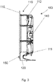
- Fig. 2 shows a wall ring axial fan with a fastening system 100 according to the invention in a plan view.
- the fan 140 is held in a wall ring serving as a fastening device 110 via holding means 111.
- the fastening device 110 has a collar 112 and a flange 119.
- First fastening geometries 115 in the form of bores are provided in the flange 119.
- the wall ring axial fan can be inserted into an annular cutout, for example of a heat exchanger wall, and can be connected to the heat exchanger wall, for example, with screws which are inserted through the first fastening geometries 115 and screwed into the heat exchanger wall.
- the fastening system 100 has a holding device 120, which is designed as an angle holder and by means of which the wall ring axial fan can be fastened, for example, to a base plate of a heat exchanger unit.
- the wall ring axial fan can be adapted to customer-specific installation situations, such as different installation heights or different fastening positions, by using different holding devices 120, without changing the underlying wall ring axial fan itself.
- the holding device 120 has two grooves as the second indexing means 122, the fastening device 110 having first indexing means 113.
- These first indexing means 113 consist of the extension of the holding means 111, which protrude beyond the outer diameter of the collar 112.
- the grooves as second indexing means 122 can first be inserted into the first indexing means 113.
- the fastening device 110 has two first guides 117 in the form of dovetail guides, into which corresponding second guides 121 on the holding device 120 are inserted in the assembled state. Before the guides 117, 121 come into engagement, the indexing means 113, 122 are engaged, as a result of which the guides 117, 121 find one another more easily and assembly is simplified.
- the fits of the indexing means 113, 122 have more play than those of the guides 117, 121.
- the guides 117, 121 have bevels in the axial direction, as a result of which they are easy to assemble and are nevertheless operatively connected to one another without play in their end position after assembly.
- Fig. 3 shows a wall ring axial fan with a fastening system, which is not part of the present invention, in a side view.
- Holding device 120 and fastening device 110 are assembled with one another and fixed to one another in this position by means of a screw 150 which is screwed through a hole in the fastening device 110 as the first fixing geometry into a blind hole in the holding device 120 as the second fixing geometry 125.
- Fig. 4 shows a detail from a fastening device of a fastening system 100 according to the invention in a three-dimensional representation.
- Two second fastening geometries 116 can be clearly seen in this illustration. These each consist of an axial undercut, onto which the holding device 120 can be pushed and thus fastened.
- the second Fastening geometries 116 each have a dovetail guide as the first guide 117.
- the flange 119 of the fastening device 110 can be seen in this illustration.
- a first fastening geometry 115 in the form of a through hole is located in the flange 119. This bore also serves as the first fixing geometry 118.
- the bore is the first fastening geometry 115 in the event that the wall ring axial fan is installed in a conventional manner in an annular cutout in a wall.
- the wall ring axial fan can be fastened in the ring-shaped cutout with a screw which is passed through this hole and screwed into the wall.
- the same bore serves as the first fixing geometry 118, whereby a screw 150 can be inserted through it, which in the second fixing geometry 125 of the holding device 120 (not shown in the figure) can be screwed when the holding device 120 is mounted in order to fix the holding device 120 to the fastening device 110.
- Fig. 5 shows a holding device 120 of a fastening system 100 according to the invention in a three-dimensional representation from a first perspective.
- the holding device 120 forms a segment of a circle.
- Two second guides 121 in the form of counterparts to a dovetail guide can be seen.
- two second indexing means 122 in the form of axial grooves on the inside diameter of the holding device 120 can be seen.
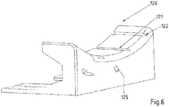
- Fig. 6 shows a holding device 120 of a fastening system 100 according to the invention in a three-dimensional representation from a second perspective.
- Fig. 7 shows a detail from an embodiment of a fastening system 100 according to the invention in a three-dimensional representation.
- a snap hook is provided on the holding device 120 as the second fixing geometry 125, which snaps behind the flange 119 of the fastening device 110 in the assembled state of the holding device 120, which acts as the first fixing geometry 118 in this embodiment.
- a screw 150 or another additional part for fixing the holding device 120 to the fastening device 110 can thus be dispensed with.
Landscapes
- Engineering & Computer Science (AREA)
- Mechanical Engineering (AREA)
- General Engineering & Computer Science (AREA)
- Structures Of Non-Positive Displacement Pumps (AREA)
- Connection Of Plates (AREA)
Claims (6)
- Système de fixation (100) pour la fixation d'un ventilateur axial avec bague de maintien mural, avec une bague de maintien mural comme dispositif de fixation (110), un ventilateur (140) et un moyen de retenue (111), sur un appareil, le dispositif de fixation (110) étant prévu dans le sens radial autour du ventilateur (140) et le ventilateur (140) étant relié au dispositif de fixation (110) avec le moyen de retenue (111), et le dispositif de fixation (110) présentant une première géométrie de fixation (115), le système de fixation (100) comprenant le dispositif de fixation (110) et en plus un dispositif de retenue (120), le dispositif de fixation (110) présentant au moins une deuxième géométrie de fixation (116) pour la fixation du dispositif de retenue (120) sur le dispositif de fixation (110), la deuxième géométrie de fixation (116) étant prévue sur la périphérie du dispositif de fixation (110), le dispositif de fixation (110) présentant, sur sa périphérie, une collerette (112), sur la périphérie de laquelle est prévue la deuxième géométrie de fixation (116), et présentant un premier guidage (117) sous la forme d'un guidage en queue d'aronde dans lequel le dispositif de retenue (120) peut être introduit, le diamètre extérieur du premier guidage (117) étant au plus égal au diamètre extérieur maximal du dispositif de fixation (110) et
le dispositif de retenue (120) présentant au moins un deuxième guidage (121) qui peut être activement relié au premier guidage (117) de la deuxième géométrie de fixation (116) et les premier et deuxième guidages (117, 121) de la deuxième géométrie de fixation (116) et du dispositif de retenue (120) présentant des chanfreins correspondants dans le sens axial, la première géométrie de fixation (115) présentant une bride (119) agissant comme première géométrie de fixation (118) et une deuxième géométrie de fixation (125) présentant un crochet d'encliquetage sur le dispositif de retenue (120). - Système de fixation (100) conformément à la revendication n°1,
caractérisé en ce que
le guidage en queue d'aronde présente une forme trapézoïdale. - Système de fixation (100) conformément à la revendication n°1,
caractérisé en ce que
le guidage en queue d'aronde présente une forme cylindrique. - Système de fixation (100) conformément à l'une des revendications précédentes,
caractérisé en ce que
le dispositif de fixation (110) présente au moins un premier moyen d'indexation (113), le dispositif de retenue (120) présentant un deuxième moyen d'indexation (122) qui interagit avec le premier moyen d'indexation (113) lors du montage du dispositif de retenue (120) avec le dispositif de fixation (113). - Système de fixation (100) conformément à la revendication n°4,
caractérisé en ce que
le premier moyen d'indexation (113) présente une saillie axiale sur la géométrie extérieure de la collerette (112) du dispositif de fixation (110) tandis que le deuxième moyen d'indexation (122) présente une rainure dans le sens axial sur le diamètre intérieur du dispositif de retenue (120). - Système de fixation (100) conformément à l'une des revendications précédentes,
caractérisé en ce que
la première géométrie de fixation (118) et la deuxième géométrie de fixation (125) peuvent être activement reliées à l'état monté.
Applications Claiming Priority (1)
| Application Number | Priority Date | Filing Date | Title |
|---|---|---|---|
| DE102014207365.0A DE102014207365A1 (de) | 2014-04-16 | 2014-04-16 | Lüfterbefestigung |
Publications (2)
| Publication Number | Publication Date |
|---|---|
| EP2933495A1 EP2933495A1 (fr) | 2015-10-21 |
| EP2933495B1 true EP2933495B1 (fr) | 2020-07-01 |
Family
ID=53005467
Family Applications (1)
| Application Number | Title | Priority Date | Filing Date |
|---|---|---|---|
| EP15163007.6A Not-in-force EP2933495B1 (fr) | 2014-04-16 | 2015-04-09 | Fixation de ventilateur |
Country Status (4)
| Country | Link |
|---|---|
| US (1) | US20150300373A1 (fr) |
| EP (1) | EP2933495B1 (fr) |
| CN (1) | CN105003466A (fr) |
| DE (1) | DE102014207365A1 (fr) |
Families Citing this family (4)
| Publication number | Priority date | Publication date | Assignee | Title |
|---|---|---|---|---|
| CN104564845B (zh) * | 2013-10-11 | 2017-07-21 | 英业达科技有限公司 | 固定件及其风扇结构 |
| GB201517171D0 (en) * | 2015-09-29 | 2015-11-11 | Rolls Royce Plc | A casing for a gas turbine engine and a method of manufacturing such a casing |
| US11846301B2 (en) | 2016-03-15 | 2023-12-19 | Trane International Inc. | Aligning a centerline of a motor shaft in a fan assembly |
| CN115217778A (zh) * | 2018-02-22 | 2022-10-21 | 美蓓亚三美株式会社 | 鼓风机装置 |
Family Cites Families (12)
| Publication number | Priority date | Publication date | Assignee | Title |
|---|---|---|---|---|
| US6358087B1 (en) * | 2000-10-16 | 2002-03-19 | General Motors Corporation | Snap-fit electrical connector |
| DE202005011514U1 (de) * | 2005-07-19 | 2005-10-13 | Arctic-Cooling Switzerland Ag | Ventilator für Computer |
| TWM334886U (en) * | 2007-12-12 | 2008-06-21 | Taiwei Fan Technology Co Ltd | Combination type miniature axial-flow fan |
| US20100111698A1 (en) * | 2008-11-06 | 2010-05-06 | Bryce Wiedeman | Fan with locking ring |
| CN201666266U (zh) * | 2009-12-07 | 2010-12-08 | 甘肃省机械科学研究院 | 用于果蔬带式干燥机的风机 |
| DE102010045899B3 (de) * | 2010-09-17 | 2012-02-16 | Ingo Schehr | Ventilatoreinheit mit einem elektrischen Axialventilator |
| CN102905503B (zh) * | 2011-07-29 | 2016-06-01 | 深圳市丰巨泰科电子有限公司 | 风扇调节装置 |
| CN103149971A (zh) * | 2011-12-06 | 2013-06-12 | 鸿富锦精密工业(武汉)有限公司 | 风扇模组 |
| JP5945912B2 (ja) * | 2012-02-09 | 2016-07-05 | 日本電産株式会社 | ファン |
| DE202012103921U1 (de) * | 2012-10-12 | 2014-01-16 | Ebm-Papst St. Georgen Gmbh & Co. Kg | Montageelement zur Befestigung eines Lüftergehäuses und Lüftergehäuse |
| US9222479B2 (en) * | 2012-08-21 | 2015-12-29 | Cooler Master Development Corporation | Fan and fan frame thereof |
| DE102012109516B4 (de) * | 2012-10-08 | 2016-08-04 | Ebm-Papst Mulfingen Gmbh & Co. Kg | "Trägerelement für einen Ventilator sowie damit ausgestatteter Ventilator" |
-
2014
- 2014-04-16 DE DE102014207365.0A patent/DE102014207365A1/de not_active Withdrawn
-
2015
- 2015-04-09 EP EP15163007.6A patent/EP2933495B1/fr not_active Not-in-force
- 2015-04-14 CN CN201510176178.6A patent/CN105003466A/zh active Pending
- 2015-04-15 US US14/687,111 patent/US20150300373A1/en not_active Abandoned
Non-Patent Citations (1)
| Title |
|---|
| None * |
Also Published As
| Publication number | Publication date |
|---|---|
| DE102014207365A1 (de) | 2015-10-22 |
| EP2933495A1 (fr) | 2015-10-21 |
| CN105003466A (zh) | 2015-10-28 |
| US20150300373A1 (en) | 2015-10-22 |
Similar Documents
| Publication | Publication Date | Title |
|---|---|---|
| DE102010045899B3 (de) | Ventilatoreinheit mit einem elektrischen Axialventilator | |
| DE102009039783B4 (de) | Zentrifugalgebläse | |
| EP2933495B1 (fr) | Fixation de ventilateur | |
| EP2338581A1 (fr) | Unité de ventilateur pour ventilateur à filtre | |
| EP2904333B1 (fr) | Élément de support pour ventilateur et ventilateur équipé d'un tel élément de support | |
| DE202008002356U1 (de) | Kompaktlüfter | |
| DE10253227A1 (de) | Lüfter, insbesondere Gerätelüfter | |
| WO2014056630A1 (fr) | Carter pour un ventilateur axial | |
| EP3158626A2 (fr) | Moteur électrique pourvu d'un rotor, d'un stator et d'un boîtier électronique et roue de ventilateur pour moteur électrique | |
| DE1428225B2 (de) | Zentrifugalgebläse | |
| WO2018153661A1 (fr) | Accouplement à fiche avec antitraction pour un câble de raccordement | |
| DE102007010465B4 (de) | Lüfterbaugruppe sowie Befestigungsanordnung für selbige | |
| DE102007014508B4 (de) | Spuleneinrichtung für Draht, insbesondere für Schweißdraht | |
| EP2525103B1 (fr) | Agencement de ventilateur | |
| EP2750269B1 (fr) | Groupe motopompe | |
| WO2016120184A1 (fr) | Système de réception | |
| DE102004005028A1 (de) | Befestigungsanordnung, Antriebsvorrichtung, Lüfterzarge und Wärmeübertrageranordnung | |
| DE10330315B4 (de) | Filterlüfter | |
| DE102020004844A1 (de) | Rotor für Elektromotoren sowie Elektromotor mit Rotor | |
| EP4293234A1 (fr) | Ventilateur, dispositif de refroidissement doté d'un tel ventilateur et boitier doté d'un tel dispositif de refroidissement | |
| DE69816204T2 (de) | Vorrichtung zur Unterstützung der Motoreinheit eines Ventilators | |
| EP2103472B1 (fr) | Dispositif de fixation, notamment pour un ou plusieurs ventilateurs | |
| DE102022123882B4 (de) | Vorrichtung zum Leiten von Kühlluft an einer Motoraufnahme für einen Ventilatormotor | |
| EP2965936A1 (fr) | Dispositif de commande de l'écoulement d'air à travers le refroidisseur d'un véhicule routier | |
| DE102007039814B4 (de) | Befestigungsvorrichtung für Gebläsemotor sowie Fahrzeuggebläse |
Legal Events
| Date | Code | Title | Description |
|---|---|---|---|
| PUAI | Public reference made under article 153(3) epc to a published international application that has entered the european phase |
Free format text: ORIGINAL CODE: 0009012 |
|
| AK | Designated contracting states |
Kind code of ref document: A1 Designated state(s): AL AT BE BG CH CY CZ DE DK EE ES FI FR GB GR HR HU IE IS IT LI LT LU LV MC MK MT NL NO PL PT RO RS SE SI SK SM TR |
|
| AX | Request for extension of the european patent |
Extension state: BA ME |
|
| 17P | Request for examination filed |
Effective date: 20160421 |
|
| RBV | Designated contracting states (corrected) |
Designated state(s): AL AT BE BG CH CY CZ DE DK EE ES FI FR GB GR HR HU IE IS IT LI LT LU LV MC MK MT NL NO PL PT RO RS SE SI SK SM TR |
|
| STAA | Information on the status of an ep patent application or granted ep patent |
Free format text: STATUS: EXAMINATION IS IN PROGRESS |
|
| 17Q | First examination report despatched |
Effective date: 20180502 |
|
| GRAP | Despatch of communication of intention to grant a patent |
Free format text: ORIGINAL CODE: EPIDOSNIGR1 |
|
| STAA | Information on the status of an ep patent application or granted ep patent |
Free format text: STATUS: GRANT OF PATENT IS INTENDED |
|
| INTG | Intention to grant announced |
Effective date: 20200213 |
|
| GRAS | Grant fee paid |
Free format text: ORIGINAL CODE: EPIDOSNIGR3 |
|
| GRAA | (expected) grant |
Free format text: ORIGINAL CODE: 0009210 |
|
| STAA | Information on the status of an ep patent application or granted ep patent |
Free format text: STATUS: THE PATENT HAS BEEN GRANTED |
|
| AK | Designated contracting states |
Kind code of ref document: B1 Designated state(s): AL AT BE BG CH CY CZ DE DK EE ES FI FR GB GR HR HU IE IS IT LI LT LU LV MC MK MT NL NO PL PT RO RS SE SI SK SM TR |
|
| REG | Reference to a national code |
Ref country code: CH Ref legal event code: EP Ref country code: AT Ref legal event code: REF Ref document number: 1286444 Country of ref document: AT Kind code of ref document: T Effective date: 20200715 |
|
| REG | Reference to a national code |
Ref country code: IE Ref legal event code: FG4D Free format text: LANGUAGE OF EP DOCUMENT: GERMAN |
|
| REG | Reference to a national code |
Ref country code: DE Ref legal event code: R096 Ref document number: 502015012892 Country of ref document: DE |
|
| REG | Reference to a national code |
Ref country code: SE Ref legal event code: TRGR |
|
| REG | Reference to a national code |
Ref country code: NL Ref legal event code: FP |
|
| REG | Reference to a national code |
Ref country code: LT Ref legal event code: MG4D |
|
| PG25 | Lapsed in a contracting state [announced via postgrant information from national office to epo] |
Ref country code: BG Free format text: LAPSE BECAUSE OF FAILURE TO SUBMIT A TRANSLATION OF THE DESCRIPTION OR TO PAY THE FEE WITHIN THE PRESCRIBED TIME-LIMIT Effective date: 20201001 |
|
| PG25 | Lapsed in a contracting state [announced via postgrant information from national office to epo] |
Ref country code: ES Free format text: LAPSE BECAUSE OF FAILURE TO SUBMIT A TRANSLATION OF THE DESCRIPTION OR TO PAY THE FEE WITHIN THE PRESCRIBED TIME-LIMIT Effective date: 20200701 Ref country code: NO Free format text: LAPSE BECAUSE OF FAILURE TO SUBMIT A TRANSLATION OF THE DESCRIPTION OR TO PAY THE FEE WITHIN THE PRESCRIBED TIME-LIMIT Effective date: 20201001 Ref country code: PT Free format text: LAPSE BECAUSE OF FAILURE TO SUBMIT A TRANSLATION OF THE DESCRIPTION OR TO PAY THE FEE WITHIN THE PRESCRIBED TIME-LIMIT Effective date: 20201102 Ref country code: LT Free format text: LAPSE BECAUSE OF FAILURE TO SUBMIT A TRANSLATION OF THE DESCRIPTION OR TO PAY THE FEE WITHIN THE PRESCRIBED TIME-LIMIT Effective date: 20200701 Ref country code: HR Free format text: LAPSE BECAUSE OF FAILURE TO SUBMIT A TRANSLATION OF THE DESCRIPTION OR TO PAY THE FEE WITHIN THE PRESCRIBED TIME-LIMIT Effective date: 20200701 Ref country code: GR Free format text: LAPSE BECAUSE OF FAILURE TO SUBMIT A TRANSLATION OF THE DESCRIPTION OR TO PAY THE FEE WITHIN THE PRESCRIBED TIME-LIMIT Effective date: 20201002 Ref country code: FI Free format text: LAPSE BECAUSE OF FAILURE TO SUBMIT A TRANSLATION OF THE DESCRIPTION OR TO PAY THE FEE WITHIN THE PRESCRIBED TIME-LIMIT Effective date: 20200701 |
|
| PG25 | Lapsed in a contracting state [announced via postgrant information from national office to epo] |
Ref country code: LV Free format text: LAPSE BECAUSE OF FAILURE TO SUBMIT A TRANSLATION OF THE DESCRIPTION OR TO PAY THE FEE WITHIN THE PRESCRIBED TIME-LIMIT Effective date: 20200701 Ref country code: PL Free format text: LAPSE BECAUSE OF FAILURE TO SUBMIT A TRANSLATION OF THE DESCRIPTION OR TO PAY THE FEE WITHIN THE PRESCRIBED TIME-LIMIT Effective date: 20200701 Ref country code: RS Free format text: LAPSE BECAUSE OF FAILURE TO SUBMIT A TRANSLATION OF THE DESCRIPTION OR TO PAY THE FEE WITHIN THE PRESCRIBED TIME-LIMIT Effective date: 20200701 Ref country code: IS Free format text: LAPSE BECAUSE OF FAILURE TO SUBMIT A TRANSLATION OF THE DESCRIPTION OR TO PAY THE FEE WITHIN THE PRESCRIBED TIME-LIMIT Effective date: 20201101 |
|
| REG | Reference to a national code |
Ref country code: DE Ref legal event code: R097 Ref document number: 502015012892 Country of ref document: DE |
|
| PG25 | Lapsed in a contracting state [announced via postgrant information from national office to epo] |
Ref country code: DK Free format text: LAPSE BECAUSE OF FAILURE TO SUBMIT A TRANSLATION OF THE DESCRIPTION OR TO PAY THE FEE WITHIN THE PRESCRIBED TIME-LIMIT Effective date: 20200701 Ref country code: EE Free format text: LAPSE BECAUSE OF FAILURE TO SUBMIT A TRANSLATION OF THE DESCRIPTION OR TO PAY THE FEE WITHIN THE PRESCRIBED TIME-LIMIT Effective date: 20200701 Ref country code: RO Free format text: LAPSE BECAUSE OF FAILURE TO SUBMIT A TRANSLATION OF THE DESCRIPTION OR TO PAY THE FEE WITHIN THE PRESCRIBED TIME-LIMIT Effective date: 20200701 Ref country code: SM Free format text: LAPSE BECAUSE OF FAILURE TO SUBMIT A TRANSLATION OF THE DESCRIPTION OR TO PAY THE FEE WITHIN THE PRESCRIBED TIME-LIMIT Effective date: 20200701 |
|
| PLBE | No opposition filed within time limit |
Free format text: ORIGINAL CODE: 0009261 |
|
| STAA | Information on the status of an ep patent application or granted ep patent |
Free format text: STATUS: NO OPPOSITION FILED WITHIN TIME LIMIT |
|
| PG25 | Lapsed in a contracting state [announced via postgrant information from national office to epo] |
Ref country code: AL Free format text: LAPSE BECAUSE OF FAILURE TO SUBMIT A TRANSLATION OF THE DESCRIPTION OR TO PAY THE FEE WITHIN THE PRESCRIBED TIME-LIMIT Effective date: 20200701 |
|
| 26N | No opposition filed |
Effective date: 20210406 |
|
| PG25 | Lapsed in a contracting state [announced via postgrant information from national office to epo] |
Ref country code: SK Free format text: LAPSE BECAUSE OF FAILURE TO SUBMIT A TRANSLATION OF THE DESCRIPTION OR TO PAY THE FEE WITHIN THE PRESCRIBED TIME-LIMIT Effective date: 20200701 |
|
| PG25 | Lapsed in a contracting state [announced via postgrant information from national office to epo] |
Ref country code: SI Free format text: LAPSE BECAUSE OF FAILURE TO SUBMIT A TRANSLATION OF THE DESCRIPTION OR TO PAY THE FEE WITHIN THE PRESCRIBED TIME-LIMIT Effective date: 20200701 |
|
| PG25 | Lapsed in a contracting state [announced via postgrant information from national office to epo] |
Ref country code: MC Free format text: LAPSE BECAUSE OF FAILURE TO SUBMIT A TRANSLATION OF THE DESCRIPTION OR TO PAY THE FEE WITHIN THE PRESCRIBED TIME-LIMIT Effective date: 20200701 |
|
| PG25 | Lapsed in a contracting state [announced via postgrant information from national office to epo] |
Ref country code: LU Free format text: LAPSE BECAUSE OF NON-PAYMENT OF DUE FEES Effective date: 20210409 |
|
| REG | Reference to a national code |
Ref country code: BE Ref legal event code: MM Effective date: 20210430 |
|
| PG25 | Lapsed in a contracting state [announced via postgrant information from national office to epo] |
Ref country code: CH Free format text: LAPSE BECAUSE OF NON-PAYMENT OF DUE FEES Effective date: 20210430 Ref country code: LI Free format text: LAPSE BECAUSE OF NON-PAYMENT OF DUE FEES Effective date: 20210430 |
|
| PG25 | Lapsed in a contracting state [announced via postgrant information from national office to epo] |
Ref country code: IE Free format text: LAPSE BECAUSE OF NON-PAYMENT OF DUE FEES Effective date: 20210409 |
|
| PG25 | Lapsed in a contracting state [announced via postgrant information from national office to epo] |
Ref country code: IS Free format text: LAPSE BECAUSE OF FAILURE TO SUBMIT A TRANSLATION OF THE DESCRIPTION OR TO PAY THE FEE WITHIN THE PRESCRIBED TIME-LIMIT Effective date: 20201101 |
|
| PG25 | Lapsed in a contracting state [announced via postgrant information from national office to epo] |
Ref country code: BE Free format text: LAPSE BECAUSE OF NON-PAYMENT OF DUE FEES Effective date: 20210430 |
|
| PGFP | Annual fee paid to national office [announced via postgrant information from national office to epo] |
Ref country code: CZ Payment date: 20230327 Year of fee payment: 9 |
|
| PG25 | Lapsed in a contracting state [announced via postgrant information from national office to epo] |
Ref country code: HU Free format text: LAPSE BECAUSE OF FAILURE TO SUBMIT A TRANSLATION OF THE DESCRIPTION OR TO PAY THE FEE WITHIN THE PRESCRIBED TIME-LIMIT; INVALID AB INITIO Effective date: 20150409 |
|
| P01 | Opt-out of the competence of the unified patent court (upc) registered |
Effective date: 20230519 |
|
| PG25 | Lapsed in a contracting state [announced via postgrant information from national office to epo] |
Ref country code: CY Free format text: LAPSE BECAUSE OF FAILURE TO SUBMIT A TRANSLATION OF THE DESCRIPTION OR TO PAY THE FEE WITHIN THE PRESCRIBED TIME-LIMIT Effective date: 20200701 |
|
| PGFP | Annual fee paid to national office [announced via postgrant information from national office to epo] |
Ref country code: NL Payment date: 20230417 Year of fee payment: 9 |
|
| PGFP | Annual fee paid to national office [announced via postgrant information from national office to epo] |
Ref country code: IT Payment date: 20230428 Year of fee payment: 9 Ref country code: FR Payment date: 20230417 Year of fee payment: 9 Ref country code: DE Payment date: 20230418 Year of fee payment: 9 |
|
| PGFP | Annual fee paid to national office [announced via postgrant information from national office to epo] |
Ref country code: SE Payment date: 20230419 Year of fee payment: 9 Ref country code: AT Payment date: 20230414 Year of fee payment: 9 |
|
| PGFP | Annual fee paid to national office [announced via postgrant information from national office to epo] |
Ref country code: GB Payment date: 20230420 Year of fee payment: 9 |
|
| PG25 | Lapsed in a contracting state [announced via postgrant information from national office to epo] |
Ref country code: MK Free format text: LAPSE BECAUSE OF FAILURE TO SUBMIT A TRANSLATION OF THE DESCRIPTION OR TO PAY THE FEE WITHIN THE PRESCRIBED TIME-LIMIT Effective date: 20200701 |
|
| PG25 | Lapsed in a contracting state [announced via postgrant information from national office to epo] |
Ref country code: MT Free format text: LAPSE BECAUSE OF FAILURE TO SUBMIT A TRANSLATION OF THE DESCRIPTION OR TO PAY THE FEE WITHIN THE PRESCRIBED TIME-LIMIT Effective date: 20200701 |
|
| REG | Reference to a national code |
Ref country code: DE Ref legal event code: R119 Ref document number: 502015012892 Country of ref document: DE |
|
| REG | Reference to a national code |
Ref country code: SE Ref legal event code: EUG |
|
| REG | Reference to a national code |
Ref country code: NL Ref legal event code: MM Effective date: 20240501 |
|
| REG | Reference to a national code |
Ref country code: AT Ref legal event code: MM01 Ref document number: 1286444 Country of ref document: AT Kind code of ref document: T Effective date: 20240409 |
|
| GBPC | Gb: european patent ceased through non-payment of renewal fee |
Effective date: 20240409 |
|
| PG25 | Lapsed in a contracting state [announced via postgrant information from national office to epo] |
Ref country code: DE Free format text: LAPSE BECAUSE OF NON-PAYMENT OF DUE FEES Effective date: 20241105 |
|
| PG25 | Lapsed in a contracting state [announced via postgrant information from national office to epo] |
Ref country code: NL Free format text: LAPSE BECAUSE OF NON-PAYMENT OF DUE FEES Effective date: 20240501 |
|
| PG25 | Lapsed in a contracting state [announced via postgrant information from national office to epo] |
Ref country code: GB Free format text: LAPSE BECAUSE OF NON-PAYMENT OF DUE FEES Effective date: 20240409 |
|
| PG25 | Lapsed in a contracting state [announced via postgrant information from national office to epo] |
Ref country code: FR Free format text: LAPSE BECAUSE OF NON-PAYMENT OF DUE FEES Effective date: 20240430 |
|
| PG25 | Lapsed in a contracting state [announced via postgrant information from national office to epo] |
Ref country code: AT Free format text: LAPSE BECAUSE OF NON-PAYMENT OF DUE FEES Effective date: 20240409 |
|
| PG25 | Lapsed in a contracting state [announced via postgrant information from national office to epo] |
Ref country code: CZ Free format text: LAPSE BECAUSE OF NON-PAYMENT OF DUE FEES Effective date: 20240409 |
|
| PG25 | Lapsed in a contracting state [announced via postgrant information from national office to epo] |
Ref country code: NL Free format text: LAPSE BECAUSE OF NON-PAYMENT OF DUE FEES Effective date: 20240501 Ref country code: GB Free format text: LAPSE BECAUSE OF NON-PAYMENT OF DUE FEES Effective date: 20240409 Ref country code: FR Free format text: LAPSE BECAUSE OF NON-PAYMENT OF DUE FEES Effective date: 20240430 Ref country code: DE Free format text: LAPSE BECAUSE OF NON-PAYMENT OF DUE FEES Effective date: 20241105 Ref country code: CZ Free format text: LAPSE BECAUSE OF NON-PAYMENT OF DUE FEES Effective date: 20240409 Ref country code: AT Free format text: LAPSE BECAUSE OF NON-PAYMENT OF DUE FEES Effective date: 20240409 |
|
| PG25 | Lapsed in a contracting state [announced via postgrant information from national office to epo] |
Ref country code: IT Free format text: LAPSE BECAUSE OF NON-PAYMENT OF DUE FEES Effective date: 20240409 |
|
| PG25 | Lapsed in a contracting state [announced via postgrant information from national office to epo] |
Ref country code: SE Free format text: LAPSE BECAUSE OF NON-PAYMENT OF DUE FEES Effective date: 20240410 |
|
| PG25 | Lapsed in a contracting state [announced via postgrant information from national office to epo] |
Ref country code: TR Free format text: LAPSE BECAUSE OF FAILURE TO SUBMIT A TRANSLATION OF THE DESCRIPTION OR TO PAY THE FEE WITHIN THE PRESCRIBED TIME-LIMIT Effective date: 20200701 |