EP2935033B1 - Tube souple - Google Patents
Tube souple Download PDFInfo
- Publication number
- EP2935033B1 EP2935033B1 EP13814108.0A EP13814108A EP2935033B1 EP 2935033 B1 EP2935033 B1 EP 2935033B1 EP 13814108 A EP13814108 A EP 13814108A EP 2935033 B1 EP2935033 B1 EP 2935033B1
- Authority
- EP
- European Patent Office
- Prior art keywords
- skirt
- tube
- flaps
- tube head
- shoulder
- Prior art date
- Legal status (The legal status is an assumption and is not a legal conclusion. Google has not performed a legal analysis and makes no representation as to the accuracy of the status listed.)
- Not-in-force
Links
- 239000000463 material Substances 0.000 claims description 13
- 230000004888 barrier function Effects 0.000 claims description 8
- 239000007788 liquid Substances 0.000 claims description 8
- 235000011837 pasties Nutrition 0.000 claims description 8
- 239000004033 plastic Substances 0.000 claims description 7
- 229920003023 plastic Polymers 0.000 claims description 7
- 238000004519 manufacturing process Methods 0.000 claims description 6
- 238000005520 cutting process Methods 0.000 claims description 4
- 238000002347 injection Methods 0.000 claims description 4
- 239000007924 injection Substances 0.000 claims description 4
- 238000000034 method Methods 0.000 claims description 4
- 239000011159 matrix material Substances 0.000 description 6
- 239000010410 layer Substances 0.000 description 3
- 229920000219 Ethylene vinyl alcohol Polymers 0.000 description 2
- UFRKOOWSQGXVKV-UHFFFAOYSA-N ethene;ethenol Chemical compound C=C.OC=C UFRKOOWSQGXVKV-UHFFFAOYSA-N 0.000 description 2
- 239000004715 ethylene vinyl alcohol Substances 0.000 description 2
- 230000001788 irregular Effects 0.000 description 2
- 238000011084 recovery Methods 0.000 description 2
- 229910052782 aluminium Inorganic materials 0.000 description 1
- XAGFODPZIPBFFR-UHFFFAOYSA-N aluminium Chemical compound [Al] XAGFODPZIPBFFR-UHFFFAOYSA-N 0.000 description 1
- 230000000295 complement effect Effects 0.000 description 1
- 230000000593 degrading effect Effects 0.000 description 1
- 238000006073 displacement reaction Methods 0.000 description 1
- 238000009826 distribution Methods 0.000 description 1
- 230000000694 effects Effects 0.000 description 1
- 229910052751 metal Inorganic materials 0.000 description 1
- 239000002184 metal Substances 0.000 description 1
- 230000035699 permeability Effects 0.000 description 1
- 239000011241 protective layer Substances 0.000 description 1
- 230000000284 resting effect Effects 0.000 description 1
- 238000007789 sealing Methods 0.000 description 1
- 239000007787 solid Substances 0.000 description 1
- 239000000243 solution Substances 0.000 description 1
- 238000003860 storage Methods 0.000 description 1
Images


Classifications
-
- B—PERFORMING OPERATIONS; TRANSPORTING
- B29—WORKING OF PLASTICS; WORKING OF SUBSTANCES IN A PLASTIC STATE IN GENERAL
- B29C—SHAPING OR JOINING OF PLASTICS; SHAPING OF MATERIAL IN A PLASTIC STATE, NOT OTHERWISE PROVIDED FOR; AFTER-TREATMENT OF THE SHAPED PRODUCTS, e.g. REPAIRING
- B29C45/00—Injection moulding, i.e. forcing the required volume of moulding material through a nozzle into a closed mould; Apparatus therefor
- B29C45/14—Injection moulding, i.e. forcing the required volume of moulding material through a nozzle into a closed mould; Apparatus therefor incorporating preformed parts or layers, e.g. injection moulding around inserts or for coating articles
- B29C45/14598—Coating tubular articles
-
- B—PERFORMING OPERATIONS; TRANSPORTING
- B29—WORKING OF PLASTICS; WORKING OF SUBSTANCES IN A PLASTIC STATE IN GENERAL
- B29C—SHAPING OR JOINING OF PLASTICS; SHAPING OF MATERIAL IN A PLASTIC STATE, NOT OTHERWISE PROVIDED FOR; AFTER-TREATMENT OF THE SHAPED PRODUCTS, e.g. REPAIRING
- B29C45/00—Injection moulding, i.e. forcing the required volume of moulding material through a nozzle into a closed mould; Apparatus therefor
- B29C45/14—Injection moulding, i.e. forcing the required volume of moulding material through a nozzle into a closed mould; Apparatus therefor incorporating preformed parts or layers, e.g. injection moulding around inserts or for coating articles
- B29C45/14008—Inserting articles into the mould
-
- B—PERFORMING OPERATIONS; TRANSPORTING
- B29—WORKING OF PLASTICS; WORKING OF SUBSTANCES IN A PLASTIC STATE IN GENERAL
- B29C—SHAPING OR JOINING OF PLASTICS; SHAPING OF MATERIAL IN A PLASTIC STATE, NOT OTHERWISE PROVIDED FOR; AFTER-TREATMENT OF THE SHAPED PRODUCTS, e.g. REPAIRING
- B29C45/00—Injection moulding, i.e. forcing the required volume of moulding material through a nozzle into a closed mould; Apparatus therefor
- B29C45/14—Injection moulding, i.e. forcing the required volume of moulding material through a nozzle into a closed mould; Apparatus therefor incorporating preformed parts or layers, e.g. injection moulding around inserts or for coating articles
- B29C45/1418—Injection moulding, i.e. forcing the required volume of moulding material through a nozzle into a closed mould; Apparatus therefor incorporating preformed parts or layers, e.g. injection moulding around inserts or for coating articles the inserts being deformed or preformed, e.g. by the injection pressure
- B29C45/14221—Injection moulding, i.e. forcing the required volume of moulding material through a nozzle into a closed mould; Apparatus therefor incorporating preformed parts or layers, e.g. injection moulding around inserts or for coating articles the inserts being deformed or preformed, e.g. by the injection pressure by tools, e.g. cutting means
-
- B—PERFORMING OPERATIONS; TRANSPORTING
- B65—CONVEYING; PACKING; STORING; HANDLING THIN OR FILAMENTARY MATERIAL
- B65D—CONTAINERS FOR STORAGE OR TRANSPORT OF ARTICLES OR MATERIALS, e.g. BAGS, BARRELS, BOTTLES, BOXES, CANS, CARTONS, CRATES, DRUMS, JARS, TANKS, HOPPERS, FORWARDING CONTAINERS; ACCESSORIES, CLOSURES, OR FITTINGS THEREFOR; PACKAGING ELEMENTS; PACKAGES
- B65D35/00—Pliable tubular containers adapted to be permanently or temporarily deformed to expel contents, e.g. collapsible tubes for toothpaste or other plastic or semi-liquid material; Holders therefor
- B65D35/02—Body construction
- B65D35/10—Body construction made by uniting or interconnecting two or more components
-
- B—PERFORMING OPERATIONS; TRANSPORTING
- B65—CONVEYING; PACKING; STORING; HANDLING THIN OR FILAMENTARY MATERIAL
- B65D—CONTAINERS FOR STORAGE OR TRANSPORT OF ARTICLES OR MATERIALS, e.g. BAGS, BARRELS, BOTTLES, BOXES, CANS, CARTONS, CRATES, DRUMS, JARS, TANKS, HOPPERS, FORWARDING CONTAINERS; ACCESSORIES, CLOSURES, OR FITTINGS THEREFOR; PACKAGING ELEMENTS; PACKAGES
- B65D35/00—Pliable tubular containers adapted to be permanently or temporarily deformed to expel contents, e.g. collapsible tubes for toothpaste or other plastic or semi-liquid material; Holders therefor
- B65D35/02—Body construction
- B65D35/12—Connections between body and closure-receiving bush
-
- B—PERFORMING OPERATIONS; TRANSPORTING
- B29—WORKING OF PLASTICS; WORKING OF SUBSTANCES IN A PLASTIC STATE IN GENERAL
- B29D—PRODUCING PARTICULAR ARTICLES FROM PLASTICS OR FROM SUBSTANCES IN A PLASTIC STATE
- B29D23/00—Producing tubular articles
- B29D23/20—Flexible squeeze tubes, e.g. for cosmetics
-
- B—PERFORMING OPERATIONS; TRANSPORTING
- B29—WORKING OF PLASTICS; WORKING OF SUBSTANCES IN A PLASTIC STATE IN GENERAL
- B29L—INDEXING SCHEME ASSOCIATED WITH SUBCLASS B29C, RELATING TO PARTICULAR ARTICLES
- B29L2023/00—Tubular articles
- B29L2023/20—Flexible squeeze tubes, e.g. for cosmetics
Definitions
- the present invention relates to the field of flexible tubes for the storage and distribution of products with liquid or pasty consistency, and methods of manufacturing such tubes.
- Flexible tubes commonly consist of a tube head associated with a skirt, the tube head comprising a neck for extracting a product contained in the tube, while the skirt forms the internal volume of the tube adapted to receive a product.
- the skirt is conventionally formed of a multilayer sheet, adapted to exhibit satisfactory mechanical strength and sealing properties.
- the tube head is however commonly made by injection of plastic material, which may be unsatisfactory for some applications because of the very aggressive nature of some products.
- GB 1445609 A base for the preamble of claim 1, discloses a tube in which the proximal end of the skirt comprises flaps embedded in the material forming the tube head.
- the present invention aims to propose a tube that does not have such disadvantages.
- covering means covering the outside of the tube head.
- the flaps are located on an outer face of said tube head.
- the present invention thus makes it possible to exploit the properties of the skirt in order to improve the mechanical properties of the tube head, and in particular its barrier effect for the protection of the product contained in the tube.
- said flaps are folded so as to cover at least 50% of the shoulder of the tube head.
- said folded flaps extend over the entire height of the neck.
- the tube head further comprises an insert disposed in abutment against the shoulder, so as to form a barrier between the tube head and a product contained in the volume. internal defined by the skirt.
- the insert is disposed on an inner face of said tube head, opposite to said outer face provided with flaps.
- an insert is positioned on the punch prior to the injection of plastic material.
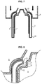
- the tube head 1 comprises a neck 11 defining a longitudinal axis ZZ and a shoulder 12 extending substantially radially from the neck 11. This defines a base 13 of the neck 11, corresponding substantially to the junction between the neck 11 having a generally cylindrical shape of revolution about the axis ZZ, and the shoulder 12 extending substantially radially relative to the axis ZZ from the neck 11.
- the neck 11 comprises a thread 14 on its outer periphery, adapted to allow screwing a cap on the neck 11 comprising a complementary thread.
- the skirt 2 is connected to the shoulder 12, so as to extend from its periphery and to form an internal volume of the tube adapted to receive a product of liquid or pasty consistency.
- the tube as shown further comprises an insert 3 disposed in abutment against the shoulder 12, resting against an inner surface of the shoulder 12, so as to form a barrier between the tube head and a product contained in the volume internal.
- the insert 3 as presented is solid, and thus forms a seal closing the neck 11. It may be an insert comprising a barrier layer, coated with one or more protective layers, in particular polymerized materials.
- the barrier layer may be metallic, in particular aluminum, or formed of EVOH.
- the skirt 2 has a proximal end 21 folded on an outer surface of the shoulder 12 and more generally on an outer surface of the tube head 1.
- the latter has a plurality of notches 23 thus defining a plurality of flaps 24 folded over the shoulder 12 of the tube head 1.
- the flaps 24 thus formed cover all or part of the shoulder 12, typically at least 50% of the surface of the shoulder 12.
- the flaps 24 are sized to extend to the base of the neck 12, and therefore cover the entirety of the shoulder 12.
- the flaps 24 can also s extend on all or part of the neck 11.
- FIGS 3 and 4 show two views of an embodiment of skirt 2 as presented above.
- the skirt 2 forms a cylinder of revolution, and has a proximal end 21 and a distal end 22.
- the proximal end 21 has a plurality of notches 23 as previously indicated, these notches 23 thus defining between them a plurality of flaps 24 formed in the material of the skirt 2.
- the notches 23 are cutouts made from the proximal end 21 of the skirt 2, substantially perpendicular to said proximal end 21, each of the notches 23 preferably having an identical length, and the notches 23 are advantageously evenly distributed along the proximal end 21 of the skirt 2.
- the notches 23 extend typically parallel to the axis ZZ, which corresponds to an axis of revolution of the skirt 2.
- the flaps 24 thus formed are then similar or identical.
- the figure 4 schematically represents the flaps 24 folded in a position corresponding substantially to the configuration of the flaps presented on the figure 2 .
- the flaps 24 form a non-zero angle with the rest of the skirt 2.
- the adjacent flaps partially overlap due to the reduction in diameter between the diameter of the cylinder of revolution of the skirt as presented on FIG. figure 3 , and the inner diameter of the reduced section defined once the flaps 24 folded.
- the folding of its proximal end 21 would have resulted in undulations and therefore an irregular surface, degrading the appearance of the associated tube head as well as its mechanical properties. makes the irregular shape of the skirt which causes an uncontrolled injection of the material forming the tube head 1.
- the length of the notches 23 determines the dimensions of the flaps 24, and thus the recovery of the shoulder 12 can be achieved; longer notches 23 allow to cover a larger surface of the shoulder 12 while avoiding undulations of the skirt 12. Inversely, the smaller the dimensions of the notches 23, the more the surface of the shoulder 12 can to be covered by fold of the skirt 2 will be weak.
- notches 23 also affects the possibility of folding the proximal end 21 of the skirt 2 without forming corrugations; the greater the number of notches 23, the smaller the dimensions of the flaps 24, and therefore the more it is possible to fold them towards the inside of the skirt 2 as shown in FIG. figure 4 without forming undulations.
- the notches 23 can also be made in a number of ways. It can be simple cuts without removal of material as represented on the figure 3 , or cuts producing a removal of material, for example a portion having a triangular shape whose base is formed by the proximal end 21 of the skirt 2; the shape of such cuts being configured according to the dimensions of the skirt 2 and the tube head 1, and the recovery by the desired skirt 2.
- the Figures 5, 6 , 7 and 8 show an example of tooling for producing such a tube, and an example of a method for producing such a tube.
- the figure 5 has a skirt 2 mounted on a tool element commonly called threader 4.
- This threader 4 has for example a cylindrical shape of revolution so as to fit the skirt 2 around, and comprises movable stops 41 according to its length, so that when moving, they slide the skirt 2 along the threader 4.
- These movable stops 41 are furthermore provided with cutting tools 42 distributed around the periphery of the threader 41, so that during the displacement of the mobile stops 41 along the threader 4, the cutting tools 42 go into firstly come into contact with the skirt 2, and thus make notches from its proximal end 21. Once these notches are formed and flaps are formed as described above, these flaps abut against the stops movable, which then cause the skirt 2 to move along the threader 4.
- the figure 6 thus presents the position of the mobile stops 41 once the notches made at the proximal end 21 of the skirt 2; the movable stops push the skirt 2 so as to come to press it around a punch 5.
- the Figures 7 and 8 show the positioning of a die 6 vis-a-vis the punch 5, the die 6 and the punch 5 defining between them an internal volume defining the shape of the tube head that is desired to achieve; so we spot on the figure 8 the shape of the shoulder 12 and the neck 11 of a tube head as defined above.
- the positioning of the matrix 6 causes the proximal end 21 of the skirt 2 to fold so that it substantially conforms to the shape of the matrix 6 defining the shoulder 12 and the where appropriate, the neck 11.
- Plastic material is then injected to form the tube head in the internal volume defined by the punch 5 and the matrix 6.
- the plastic material thus injected will then bond with the skirt 2, ensuring the cohesion between the skirt 2 and the tube head 1.
- an insert 3 is positioned on the punch 5 prior to the positioning of the skirt 2 or prior to the positioning of the die 6, thus making it possible to bind the tube head 1 to the insert 3 during its manufacture.
- the present invention thus makes it possible to exploit the properties of the skirt 2 in order to improve the mechanical properties of the tube head 1.
- the invention makes it possible to improve the properties of the tube head 1 by greatly reducing the permeability at the edge of the insert 3.
Landscapes
- Engineering & Computer Science (AREA)
- Mechanical Engineering (AREA)
- Manufacturing & Machinery (AREA)
- Tubes (AREA)
- Closures For Containers (AREA)
Description
- La présente invention concerne le domaine des tubes souples pour le stockage et la distribution de produits à consistance liquide ou pâteuse, et les procédés de fabrication de tels tubes.
- Les tubes souples sont communément constitués d'une tête de tube associée à une jupe, la tête de tube comprenant un goulot pour l'extraction d'un produit contenu dans le tube, tandis que la jupe forme le volume interne du tube adapté pour recevoir un produit.
- La jupe est conventionnellement formée d'une feuille multicouche, adaptée pour présenter des propriétés de résistance mécanique et d'étanchéité satisfaisantes.
- La tête de tube est en revanche communément réalisée par injection de matériau plastique, ce qui peut s'avérer non satisfaisant pour certaines applications du fait de la nature très agressive de certains produits.
- Afin de répondre à cette problématique, plusieurs solutions ont été proposées, comprenant notamment un insert comprenant une couche barrière métallique ou d'EVOH se conformant à la face interne de l'épaule de la tête de tube, de manière à former une barrière séparant la tête de tube en elle-même du produit contenu dans le tube et ainsi la protéger.
- Toutefois, bien qu'un tel insert contribue à améliorer les propriétés de la tête de tube, cette dernière présente plusieurs zones ayant des propriétés moindres, notamment en bordure de l'insert, Le document
GB 1445609 A - La présente invention vise à proposer un tube ne présentant pas de tels inconvénients.
- A cet effet, l'invention propose un tube souple pour produit à consistance liquide ou pâteuse, comprenant :
- une tête de tube comprenant une épaule et un goulot,
- une jupe présentant une extrémité proximale liée à la tête de tube et une extrémité distale libre, la jupe formant un volume interne adaptée pour contenir le produit à consistance liquide ou pâteuse,
- On entend par « recouvrir » ou «recouvrement » le fait de couvrir extérieurement la tête de tube. Autrement dit, les volets sont situés sur une face extérieure de ladite tête de tube.
- La présente invention permet ainsi d'exploiter les propriétés de la jupe afin d'améliorer les propriétés mécaniques de la tête de tube, et en particulier son effet barrière pour la protection du produit contenu dans le tube.
- Selon un mode de réalisation particulier, lesdits volets sont repliés de manière à couvrir au moins 50% de l'épaule de la tête de tube.
- Selon un mode de réalisation particulier, lesdits volets repliés s'étendent sur toute la hauteur du goulot.
- Selon un mode de réalisation particulier, la tête de tube comprend en outre un insert disposé en appui contre l'épaule, de manière à former une barrière entre la tête de tube et un produit contenu dans le volume interne défini par la jupe. Autrement dit, l'insert est disposé sur une face intérieure de ladite tête de tube, opposée à ladite face extérieure munie des volets.
- L'invention concerne également un procédé de fabrication d'un tube pour produit à consistance liquide ou pâteuse dans lequel
- on positionne une jupe formant un cylindre de révolution autour d'un enfileur, ladite jupe présentant une extrémité proximale et une extrémité distale,
- on fait coulisser la jupe le long dudit enfileur au moyen de butées mobiles muni d'une pluralité d'outils de coupe, de manière à réaliser une pluralité d'encoches à partir de l'extrémité proximale de la jupe, définissant ainsi une pluralité de volets à l'extrémité proximale de la jupe, et de manière à emmancher la jupe autour d'un poinçon ;
- on positionne une matrice autour dudit poinçon, la matrice formant avec le poinçon un logement définissant une forme de tête de tube comprenant une épaule et un goulot, ladite matrice repliant les volets de la jupe de manière à ce qu'ils se conforment à la matrice sur tout ou partie du logement définissant l'épaule ;
- on injecte de la matière plastique dans ledit logement de manière à former la tête de tube.
- Selon un mode de réalisation particulier, on positionne un insert sur le poinçon préalablement à l'injection de matière plastique.
- D'autres caractéristiques, buts et avantages de l'invention ressortiront de la description qui suit, qui est purement illustrative et non limitative, et qui doit être lue en regard des dessins annexés, sur lesquels :
- Les
figures 1 et 2 présentent des vues partielles d'un tube selon un aspect de l'invention. - Les
figures 3 et 4 présentent deux vues d'un mode de réalisation de jupe d'un tel tube. - Les
figures 5, 6 ,7 et 8 présentent un exemple d'outillage pour la réalisation d'un tel tube, et un exemple de procédé de réalisation d'un tel tube. - Sur l'ensemble des figures, les éléments en commun sont repérés par des références numériques identiques.
- Les
figures 1 et 2 présentent des vues partielles d'un tube selon un aspect de l'invention, comprenant - une tête de tube 1,
- une jupe 2, et
- un insert 3 optionnel.
- La tête de tube 1 comprend un goulot 11 définissant un axe longitudinal Z-Z et une épaule 12 s'étendant sensiblement radialement à partir du goulot 11.
On définit ainsi une base 13 du goulot 11, correspondant sensiblement à la jonction entre le goulot 11 ayant une forme générale cylindrique de révolution autour de l'axe Z-Z, et l'épaule 12 s'étendant sensiblement radialement par rapport à l'axe Z-Z à partir du goulot 11. - Le goulot 11 comprend un filetage 14 sur sa périphérie externe, adapté pour permettre de visser un bouchon sur le goulot 11 comprenant un taraudage complémentaire.
- La jupe 2 est liée à l'épaule 12, de manière à s'étendre à partir de sa périphérie et à former un volume interne du tube adapté pour recevoir un produit de consistance liquide ou pâteuse.
- Le tube tel que présenté comprend en outre un insert 3 disposé en appui contre l'épaule 12, en appui contre une surface interne de l'épaule 12, de manière à former une barrière entre la tête de tube et un produit contenu dans le volume interne.
L'insert 3 tel que présenté est plein, et forme ainsi un opercule obturant le goulot 11. Il peut s'agir d'un insert comprenant une couche barrière, revêtue d'une ou plusieurs couches de protection, notamment en matériaux polymérisés. La couche barrière peut être métallique, notamment en aluminium, ou formée d'EVOH. - Comme représenté sur la
figure 2 , la jupe 2 présente une extrémité proximale 21 repliée sur une surface externe de l'épaule 12 et plus généralement sur une surface externe de la tête de tube 1. Afin de permettre un tel repli sans générer d'ondulations au niveau de cette extrémité proximale 21 de la jupe 2, cette dernière présente une pluralité d'encoches 23 définissant ainsi une pluralité de volets 24 repliés sur l'épaule 12 de la tête de tube 1.
Les volets 24 ainsi formés recouvrent tout ou partie de l'épaule 12, typiquement au moins 50% de la surface de l'épaule 12.
Selon un mode de réalisation particulier non représenté, les volets 24 sont dimensionnés de manière à s'étendre jusqu'à la base du goulot 12, et recouvrent donc l'intégralité de l'épaule 12. En variante, les volets 24 peuvent également s'étendre sur tout ou partie du goulot 11. - Les
figures 3 et 4 présentent deux vues d'un mode de réalisation de jupe 2 telle que présentée précédemment. - La jupe 2 forme un cylindre de révolution, et présente une extrémité proximale 21 et une extrémité distale 22.
L'extrémité proximale 21 présente une pluralité d'encoches 23 comme indiqué précédemment, ces encoches 23 définissant ainsi entre elles une pluralité de volets 24 formés dans le matériau de la jupe 2. - Dans le mode de réalisation représenté, les encoches 23 sont des découpes réalisées à partir de l'extrémité proximale 21 de la jupe 2, sensiblement perpendiculairement à ladite extrémité proximale 21, chacune des encoches 23 ayant avantageusement une longueur identique, et les encoches 23 sont avantageusement réparties régulièrement le long de l'extrémité proximale 21 de la jupe 2. Les encoches 23 s'étendent typiquement parallèlement à l'axe Z-Z, qui correspond à un axe de révolution de la jupe 2.
Les volets 24 ainsi formés sont alors similaires ou identiques. - La
figure 4 représente de manière schématique les volets 24 repliés, dans une position correspondant sensiblement à la configuration des volets présentée sur lafigure 2 . Dans cette configuration, les volets 24 forment un angle non-nul avec le reste de la jupe 2.
On voit sur cette figure que les volets adjacents se recouvrent partiellement du fait de la réduction de diamètre entre le diamètre du cylindre de révolution de la jupe telle que présentée sur lafigure 3 , et le diamètre interne de la section réduite définie une fois les volets 24 repliés.
On comprend bien qu'en l'absence des encoches 23 réalisées dans la jupe 2, le repli de son extrémité proximale 21 aurait entrainé des ondulations donc une surface irrégulière, dégradant l'aspect de la tête de tube associée ainsi que ses propriétés mécaniques du fait de la forme irrégulière de la jupe qui provoque une injection non contrôlée du matériau formant la tête de tube 1. - La longueur des encoches 23 détermine les dimensions des volets 24, et donc le recouvrement de l'épaule 12 pouvant être réalisé ; des encoches 23 plus longues permettent de recouvrir une surface plus importante de l'épaule 12 tout en évitant des ondulations de la jupe 12. A l'inverse, plus les dimensions des encoches 23 sont faibles, plus la surface de l'épaule 12 pouvant être recouverte par repli de la jupe 2 sera faible.
- On comprend bien également que le nombre d'encoches 23 influe également sur la possibilité de replier l'extrémité proximale 21 de la jupe 2 sans former d'ondulations ; plus le nombre d'encoches 23 est important, plus les dimensions des volets 24 sont faibles, et donc plus il est possible de les replier vers l'intérieur de la jupe 2 comme représenté sur la
figure 4 sans former des ondulations. - Les encoches 23 peuvent également être réalisées de plusieurs manières. Il peut s'agir de simples découpes sans enlèvement de matière comme représenté sur la
figure 3 , ou des découpes réalisant un enlèvement de matière, par exemple d'une portion ayant une forme triangulaire dont la base est formée par l'extrémité proximale 21 de la jupe 2 ; la forme de telles découpes étant configurée en fonction des dimensions de la jupe 2 et de la tête de tube 1, et du recouvrement par la jupe 2 recherché. - A titre d'exemple, on indique les variantes non limitatives suivantes :
- le diamètre de la jupe 2 peut varier entre 19 et 50mm,
- pour une jupe 2 ayant un diamètre de 25mm, le nombre d'encoches peut varier entre 12 et 32 encoches,
- la largeur des encoches au niveau de l'extrémité proximale de la jupe varie typiquement entre 2mm et 6mm,
- le recouvrement est typiquement compris entre 0,2mm et 1mm.
- Les
figures 5, 6 ,7 et 8 présentent un exemple d'outillage pour la réalisation d'un tel tube, et un exemple de procédé de réalisation d'un tel tube. - La
figure 5 présente une jupe 2 montée sur un élément d'outillage communément appelé enfileur 4. Cet enfileur 4 a par exemple une forme cylindrique de révolution de manière à pouvoir emmancher la jupe 2 autour, et comprend des butées mobiles 41 mobiles selon sa longueur, de manière à ce que lors de leur déplacement, elles fassent coulisser la jupe 2 le long de l'enfileur 4.
Ces butées mobiles 41 sont en outre munies d'outils de coupe 42 répartis autour de la périphérie de l'enfileur 41, de sorte que lors du déplacement des butées mobiles 41 le long de l'enfileur 4, les outils de coupe 42 vont dans un premier temps entrer au contact avec la jupe 2, et ainsi réaliser des encoches à partir de son extrémité proximale 21. Une fois que ces encoches sont réalisées et que des volets sont formés tels que décrits précédemment, ces volets viennent en butée contre les butées mobiles, qui entraînent alors la jupe 2 en déplacement le long de l'enfileur 4. - La
figure 6 présente ainsi la position des butées mobiles 41 une fois les encoches réalisées au niveau de l'extrémité proximale 21 de la jupe 2 ; les butées mobiles poussent la jupe 2 de manière à venir l'emmancher autour d'un poinçon 5. - Les
figures 7 et 8 présentent le positionnement d'une matrice 6 vis-à-vis du poinçon 5, la matrice 6 et le poinçon 5 définissant entre eux un volume interne définissant la forme de la tête de tube que l'on souhaite réaliser ; on repère ainsi sur lafigure 8 la forme de l'épaule 12 et le goulot 11 d'une tête de tube telle que définie précédemment. - Comme représenté sur les figures, le positionnement de la matrice 6 provoque le repli de l'extrémité proximale 21 de la jupe 2, de manière à ce qu'elle se conforme sensiblement à la forme de la matrice 6 définissant l'épaule 12 et le cas échéant le goulot 11.
- On injecte ensuite de la matière plastique pour former la tête de tube dans le volume interne défini par le poinçon 5 et la matrice 6. La matière plastique ainsi injectée va alors se lier avec la jupe 2, assurant la cohésion entre la jupe 2 et la tête de tube 1.
- En variante, on positionne un insert 3 sur le poinçon 5 préalablement au positionnement de la jupe 2 ou préalablement au positionnement de la matrice 6, permettant ainsi de lier la tête de tube 1 à l'insert 3 lors de sa fabrication.
- La présente invention permet ainsi d'exploiter les propriétés de la jupe 2 afin d'améliorer les propriétés mécaniques de la tête de tube 1.
En outre, dans le cas d'une tête de tube 1 comprenant un insert 3, l'invention permet d'améliorer les propriétés de la tête de tube 1 en réduisant fortement la perméabilité en bordure de l'insert 3.
Claims (6)
- Tube souple pour produit à consistance liquide ou pâteuse, comprenant :- une tête de tube (1) comprenant une épaule (12) et un goulot (11),- une jupe (2) présentant une extrémité proximale (21) liée à la tête de tube (1) et une extrémité distale (22) libre, la jupe (2) formant un volume interne adaptée pour contenir un produit à consistance liquide ou pâteuse,caractérisé en ce que l'extrémité proximale (21) de ladite jupe (2) comprend une pluralité de volets (24) et une pluralité d'encoches (23) séparant lesdits volets (24), lesdits volets (24) étant repliés de manière à recouvrir tout ou partie de l'épaule (12).
- Tube selon la revendication 1, dans lequel lesdits volets (24) sont repliés de manière à couvrir au moins 50% de l'épaule (12) de la tête de tube (1).
- Tube selon l'une des revendications 1 ou 2, dans lequel lesdits volets (24) repliés s'étendent sur toute la hauteur du goulot (11).
- Tube selon l'une des revendications 1 à 3, dans lequel la tête de tube (1) comprend en outre un insert (3) disposé en appui contre l'épaule (12), de manière à former une barrière entre la tête de tube (1) et un produit contenu dans le volume interne défini par la jupe (2).
- Procédé de fabrication d'un tube pour produit à consistance liquide ou pâteuse dans lequel- on positionne une jupe (2) formant un cylindre de révolution autour d'un enfileur (4), ladite jupe (2) présentant une extrémité proximale (21) et une extrémité distale (22),- on fait coulisser la jupe (2) le long dudit enfileur (4) au moyen de butées mobiles (41) muni d'une pluralité d'outils de coupe (42), de manière à réaliser une pluralité d'encoches (23) à partir de l'extrémité proximale (21) de la jupe (2), définissant ainsi une pluralité de volets (24) à l'extrémité proximale (21) de la jupe (2), et de manière à emmancher la jupe (2) autour d'un poinçon (5) ;- on positionne une matrice (6) autour dudit poinçon (5), la matrice (6) formant avec le poinçon (5) un logement définissant une forme de tête de tube (1) comprenant une épaule (12) et un goulot (11), ladite matrice (6) repliant les volets (24) de la jupe (2) de manière à ce qu'ils se conforment à la matrice (6) sur tout ou partie du logement définissant l'épaule (12) ;- on injecte de la matière plastique dans ledit logement de manière à former la tête de tube (1).
- Procédé selon la revendication 5, dans lequel on positionne un insert (3) sur le poinçon (5) préalablement à l'injection de matière plastique.
Priority Applications (1)
| Application Number | Priority Date | Filing Date | Title |
|---|---|---|---|
| PL13814108T PL2935033T3 (pl) | 2012-12-21 | 2013-12-18 | Tubka giętka |
Applications Claiming Priority (2)
| Application Number | Priority Date | Filing Date | Title |
|---|---|---|---|
| FR1262732A FR3000035B1 (fr) | 2012-12-21 | 2012-12-21 | Tube ameliore exploitant les proprietes de la jupe pour la tete de tube. |
| PCT/EP2013/077175 WO2014096056A1 (fr) | 2012-12-21 | 2013-12-18 | Tube amélioré exploitant les propriétés de la jupe pour la tête de tube |
Publications (2)
| Publication Number | Publication Date |
|---|---|
| EP2935033A1 EP2935033A1 (fr) | 2015-10-28 |
| EP2935033B1 true EP2935033B1 (fr) | 2016-10-05 |
Family
ID=48224906
Family Applications (1)
| Application Number | Title | Priority Date | Filing Date |
|---|---|---|---|
| EP13814108.0A Not-in-force EP2935033B1 (fr) | 2012-12-21 | 2013-12-18 | Tube souple |
Country Status (8)
| Country | Link |
|---|---|
| US (1) | US10124520B2 (fr) |
| EP (1) | EP2935033B1 (fr) |
| CN (1) | CN104884361B (fr) |
| BR (1) | BR112015014249B1 (fr) |
| FR (1) | FR3000035B1 (fr) |
| MX (1) | MX369528B (fr) |
| PL (1) | PL2935033T3 (fr) |
| WO (1) | WO2014096056A1 (fr) |
Families Citing this family (7)
| Publication number | Priority date | Publication date | Assignee | Title |
|---|---|---|---|---|
| FR3012349B1 (fr) * | 2013-10-29 | 2020-07-31 | Albea Services | Tete de tube comprenant un insert formant barriere |
| EP3281881B1 (fr) * | 2015-04-08 | 2019-08-14 | Fujimori Kogyo Co., Ltd. | Réceptacle tubulaire |
| US11191316B2 (en) | 2017-04-26 | 2021-12-07 | Fend Corp. | Collapsible helmet |
| CN108482853B (zh) * | 2018-03-28 | 2023-11-14 | 广东工业大学 | 一种鸡蛋托具 |
| ES2911638T3 (es) * | 2019-04-24 | 2022-05-20 | Ctl Th Packaging S L Unipersonal | Envase tubular con un tubo exterior y un contenedor interior |
| KR102076661B1 (ko) * | 2019-05-31 | 2020-02-13 | 임종수 | 숄더 및 네크에 차단 기능을 갖는 튜브용기 및 그의 제조방법 |
| FR3096967B1 (fr) * | 2019-06-07 | 2021-06-25 | Albea Services | Ensemble pour la fermeture d’un tube et tube comprenant cet ensemble |
Family Cites Families (11)
| Publication number | Priority date | Publication date | Assignee | Title |
|---|---|---|---|---|
| US2352384A (en) * | 1941-07-12 | 1944-06-27 | Victor Metal Products Corp | Tin-coated collapsible tube |
| US2401784A (en) * | 1943-01-02 | 1946-06-11 | Zahara Walter | Collapsible tube |
| US3260411A (en) * | 1964-07-13 | 1966-07-12 | American Can Co | Collapsible container structure |
| CH541409A (de) * | 1972-11-24 | 1973-09-15 | Hoffmann Ag Geb | Verfahren zum Herstellen eines gas- und flüssigkeitsdichten Behälters, insbesondere einer Tube |
| CH652966A5 (de) * | 1981-05-07 | 1985-12-13 | Maegerle Karl Lizenz | Verfahren zur herstellung eines verpackungsbehaelters und nach diesem hergestellter tubenfoermiger behaelter. |
| JPS61103336U (fr) * | 1984-12-12 | 1986-07-01 | ||
| CA2212462A1 (fr) * | 1995-02-13 | 1996-08-22 | The Procter & Gamble Company | Emballage tubulaire souple et procede de construction |
| US6846443B1 (en) * | 2000-03-16 | 2005-01-25 | Pechiney Plastic Packaging, Inc | Method for forming an improved container |
| FR2806385B1 (fr) * | 2000-03-17 | 2002-12-06 | Cep Ind | Tube souple, resistant a la fissuration sous contrainte et impermeable a la vapeur d'eau |
| BRPI0710158A2 (pt) * | 2006-04-19 | 2011-08-23 | Colgate Palmolive Co | recipiente para substáncias |
| CN201856966U (zh) * | 2010-06-01 | 2011-06-08 | 广州市丽莹日化有限公司 | 一种便于开启的软膏体包装管 |
-
2012
- 2012-12-21 FR FR1262732A patent/FR3000035B1/fr not_active Expired - Fee Related
-
2013
- 2013-12-18 MX MX2015007965A patent/MX369528B/es active IP Right Grant
- 2013-12-18 PL PL13814108T patent/PL2935033T3/pl unknown
- 2013-12-18 CN CN201380065704.0A patent/CN104884361B/zh not_active Expired - Fee Related
- 2013-12-18 WO PCT/EP2013/077175 patent/WO2014096056A1/fr not_active Ceased
- 2013-12-18 US US14/652,281 patent/US10124520B2/en not_active Expired - Fee Related
- 2013-12-18 EP EP13814108.0A patent/EP2935033B1/fr not_active Not-in-force
- 2013-12-18 BR BR112015014249-4A patent/BR112015014249B1/pt not_active IP Right Cessation
Non-Patent Citations (1)
| Title |
|---|
| None * |
Also Published As
| Publication number | Publication date |
|---|---|
| MX2015007965A (es) | 2015-10-08 |
| US20150344191A1 (en) | 2015-12-03 |
| CN104884361B (zh) | 2017-11-17 |
| US10124520B2 (en) | 2018-11-13 |
| BR112015014249B1 (pt) | 2021-01-26 |
| PL2935033T3 (pl) | 2017-05-31 |
| CN104884361A (zh) | 2015-09-02 |
| WO2014096056A1 (fr) | 2014-06-26 |
| FR3000035B1 (fr) | 2016-01-08 |
| BR112015014249A2 (pt) | 2017-07-11 |
| MX369528B (es) | 2019-11-11 |
| FR3000035A1 (fr) | 2014-06-27 |
| EP2935033A1 (fr) | 2015-10-28 |
Similar Documents
| Publication | Publication Date | Title |
|---|---|---|
| EP2935033B1 (fr) | Tube souple | |
| EP2868591B1 (fr) | Tête de tube comprenant un insert formant barrière | |
| EP2201870B1 (fr) | Appareil de cuisson d'aliments sous pression à mâchoires allégées et procédé de fabrication | |
| EP2703312B1 (fr) | Tête de tube améliorée comprenant un insert formant barrière | |
| FR3021244A1 (fr) | Procede de fabrication d'un bouchon pour un col de recipient | |
| EP1833730B1 (fr) | Tube a section ovale, son procede de fabrication et dispositif pour sa mise en oeuvre | |
| EP2489601A1 (fr) | Tête de tube munie d'une valve anti retour d'air | |
| EP2931454B1 (fr) | Procédé d'assemblage par sertissage magnétique | |
| EP2932139B1 (fr) | Joint pour connexion electrique | |
| FR2766879A1 (fr) | Perfectionnement d'un corps de pompe et procede de fabrication | |
| EP3048061B1 (fr) | Boîte cylindrique à dispositif de bouchage en liège | |
| BE1022710B1 (fr) | Valve de distribution pour dispositif de distribution de produit pressurisé et procédé d'assemblage d'une telle valve | |
| EP2269805A1 (fr) | Piston de positionnement d'un décor de pot alimentaire dans un moule, dispositif et procédé associes | |
| EP1473503B1 (fr) | Conduit souple à ondulations équipé d'au moins un anneau métallique de maintien et son procédé de fabrication. | |
| EP2399840B1 (fr) | Ensemble de bouchage sécurisé | |
| WO2018073042A1 (fr) | Dispositif de distribution de produit pressurisé, procede et machine d'assemblage d'un tel dispositif | |
| EP1693606A1 (fr) | Joint métallique comportant une surépaisseur formée de protubérances discontinues | |
| EP2921418B1 (fr) | Tube amélioré exploitant les propriétés de la jupe pour la tête de tube | |
| FR2952619A1 (fr) | Distributeur de produit fluide. | |
| EP2890619B1 (fr) | Tête de tube ameliorée comprenant un insert formant barrière et permettant un centrage dudit insert | |
| WO2022189740A1 (fr) | Procédé de bouchage de tube et emballage tubulaire obtenu selon le procédé | |
| EP2202432A1 (fr) | Joint d'etanchéité | |
| FR2775045A1 (fr) | Procede de montage d'un joint souple sur une piece et piece equipee d'un tel joint | |
| EP2354604B1 (fr) | Joint métallique comportant une surépaisseur formée par au moins une nervure en lacets | |
| FR3153601A1 (fr) | Tube monomateriau equipe d'une tete de tube presentant une forme ovale |
Legal Events
| Date | Code | Title | Description |
|---|---|---|---|
| PUAI | Public reference made under article 153(3) epc to a published international application that has entered the european phase |
Free format text: ORIGINAL CODE: 0009012 |
|
| 17P | Request for examination filed |
Effective date: 20150608 |
|
| AK | Designated contracting states |
Kind code of ref document: A1 Designated state(s): AL AT BE BG CH CY CZ DE DK EE ES FI FR GB GR HR HU IE IS IT LI LT LU LV MC MK MT NL NO PL PT RO RS SE SI SK SM TR |
|
| AX | Request for extension of the european patent |
Extension state: BA ME |
|
| DAX | Request for extension of the european patent (deleted) | ||
| GRAP | Despatch of communication of intention to grant a patent |
Free format text: ORIGINAL CODE: EPIDOSNIGR1 |
|
| INTG | Intention to grant announced |
Effective date: 20160715 |
|
| GRAS | Grant fee paid |
Free format text: ORIGINAL CODE: EPIDOSNIGR3 |
|
| GRAA | (expected) grant |
Free format text: ORIGINAL CODE: 0009210 |
|
| AK | Designated contracting states |
Kind code of ref document: B1 Designated state(s): AL AT BE BG CH CY CZ DE DK EE ES FI FR GB GR HR HU IE IS IT LI LT LU LV MC MK MT NL NO PL PT RO RS SE SI SK SM TR |
|
| REG | Reference to a national code |
Ref country code: GB Ref legal event code: FG4D Free format text: NOT ENGLISH |
|
| REG | Reference to a national code |
Ref country code: CH Ref legal event code: EP |
|
| REG | Reference to a national code |
Ref country code: AT Ref legal event code: REF Ref document number: 834412 Country of ref document: AT Kind code of ref document: T Effective date: 20161015 |
|
| REG | Reference to a national code |
Ref country code: IE Ref legal event code: FG4D Free format text: LANGUAGE OF EP DOCUMENT: FRENCH |
|
| REG | Reference to a national code |
Ref country code: DE Ref legal event code: R096 Ref document number: 602013012572 Country of ref document: DE |
|
| REG | Reference to a national code |
Ref country code: FR Ref legal event code: PLFP Year of fee payment: 4 |
|
| REG | Reference to a national code |
Ref country code: NL Ref legal event code: MP Effective date: 20161005 |
|
| REG | Reference to a national code |
Ref country code: LT Ref legal event code: MG4D |
|
| PG25 | Lapsed in a contracting state [announced via postgrant information from national office to epo] |
Ref country code: LV Free format text: LAPSE BECAUSE OF FAILURE TO SUBMIT A TRANSLATION OF THE DESCRIPTION OR TO PAY THE FEE WITHIN THE PRESCRIBED TIME-LIMIT Effective date: 20161005 |
|
| REG | Reference to a national code |
Ref country code: AT Ref legal event code: MK05 Ref document number: 834412 Country of ref document: AT Kind code of ref document: T Effective date: 20161005 |
|
| PG25 | Lapsed in a contracting state [announced via postgrant information from national office to epo] |
Ref country code: NO Free format text: LAPSE BECAUSE OF FAILURE TO SUBMIT A TRANSLATION OF THE DESCRIPTION OR TO PAY THE FEE WITHIN THE PRESCRIBED TIME-LIMIT Effective date: 20170105 Ref country code: GR Free format text: LAPSE BECAUSE OF FAILURE TO SUBMIT A TRANSLATION OF THE DESCRIPTION OR TO PAY THE FEE WITHIN THE PRESCRIBED TIME-LIMIT Effective date: 20170106 Ref country code: SE Free format text: LAPSE BECAUSE OF FAILURE TO SUBMIT A TRANSLATION OF THE DESCRIPTION OR TO PAY THE FEE WITHIN THE PRESCRIBED TIME-LIMIT Effective date: 20161005 Ref country code: LT Free format text: LAPSE BECAUSE OF FAILURE TO SUBMIT A TRANSLATION OF THE DESCRIPTION OR TO PAY THE FEE WITHIN THE PRESCRIBED TIME-LIMIT Effective date: 20161005 |
|
| PG25 | Lapsed in a contracting state [announced via postgrant information from national office to epo] |
Ref country code: AT Free format text: LAPSE BECAUSE OF FAILURE TO SUBMIT A TRANSLATION OF THE DESCRIPTION OR TO PAY THE FEE WITHIN THE PRESCRIBED TIME-LIMIT Effective date: 20161005 Ref country code: IS Free format text: LAPSE BECAUSE OF FAILURE TO SUBMIT A TRANSLATION OF THE DESCRIPTION OR TO PAY THE FEE WITHIN THE PRESCRIBED TIME-LIMIT Effective date: 20170205 Ref country code: FI Free format text: LAPSE BECAUSE OF FAILURE TO SUBMIT A TRANSLATION OF THE DESCRIPTION OR TO PAY THE FEE WITHIN THE PRESCRIBED TIME-LIMIT Effective date: 20161005 Ref country code: HR Free format text: LAPSE BECAUSE OF FAILURE TO SUBMIT A TRANSLATION OF THE DESCRIPTION OR TO PAY THE FEE WITHIN THE PRESCRIBED TIME-LIMIT Effective date: 20161005 Ref country code: PT Free format text: LAPSE BECAUSE OF FAILURE TO SUBMIT A TRANSLATION OF THE DESCRIPTION OR TO PAY THE FEE WITHIN THE PRESCRIBED TIME-LIMIT Effective date: 20170206 Ref country code: RS Free format text: LAPSE BECAUSE OF FAILURE TO SUBMIT A TRANSLATION OF THE DESCRIPTION OR TO PAY THE FEE WITHIN THE PRESCRIBED TIME-LIMIT Effective date: 20161005 Ref country code: NL Free format text: LAPSE BECAUSE OF FAILURE TO SUBMIT A TRANSLATION OF THE DESCRIPTION OR TO PAY THE FEE WITHIN THE PRESCRIBED TIME-LIMIT Effective date: 20161005 Ref country code: ES Free format text: LAPSE BECAUSE OF FAILURE TO SUBMIT A TRANSLATION OF THE DESCRIPTION OR TO PAY THE FEE WITHIN THE PRESCRIBED TIME-LIMIT Effective date: 20161005 Ref country code: BE Free format text: LAPSE BECAUSE OF NON-PAYMENT OF DUE FEES Effective date: 20161231 |
|
| REG | Reference to a national code |
Ref country code: DE Ref legal event code: R097 Ref document number: 602013012572 Country of ref document: DE |
|
| PG25 | Lapsed in a contracting state [announced via postgrant information from national office to epo] |
Ref country code: EE Free format text: LAPSE BECAUSE OF FAILURE TO SUBMIT A TRANSLATION OF THE DESCRIPTION OR TO PAY THE FEE WITHIN THE PRESCRIBED TIME-LIMIT Effective date: 20161005 Ref country code: SK Free format text: LAPSE BECAUSE OF FAILURE TO SUBMIT A TRANSLATION OF THE DESCRIPTION OR TO PAY THE FEE WITHIN THE PRESCRIBED TIME-LIMIT Effective date: 20161005 Ref country code: CZ Free format text: LAPSE BECAUSE OF FAILURE TO SUBMIT A TRANSLATION OF THE DESCRIPTION OR TO PAY THE FEE WITHIN THE PRESCRIBED TIME-LIMIT Effective date: 20161005 Ref country code: DK Free format text: LAPSE BECAUSE OF FAILURE TO SUBMIT A TRANSLATION OF THE DESCRIPTION OR TO PAY THE FEE WITHIN THE PRESCRIBED TIME-LIMIT Effective date: 20161005 Ref country code: RO Free format text: LAPSE BECAUSE OF FAILURE TO SUBMIT A TRANSLATION OF THE DESCRIPTION OR TO PAY THE FEE WITHIN THE PRESCRIBED TIME-LIMIT Effective date: 20161005 |
|
| REG | Reference to a national code |
Ref country code: CH Ref legal event code: PL |
|
| PLBE | No opposition filed within time limit |
Free format text: ORIGINAL CODE: 0009261 |
|
| STAA | Information on the status of an ep patent application or granted ep patent |
Free format text: STATUS: NO OPPOSITION FILED WITHIN TIME LIMIT |
|
| PG25 | Lapsed in a contracting state [announced via postgrant information from national office to epo] |
Ref country code: BG Free format text: LAPSE BECAUSE OF FAILURE TO SUBMIT A TRANSLATION OF THE DESCRIPTION OR TO PAY THE FEE WITHIN THE PRESCRIBED TIME-LIMIT Effective date: 20170105 Ref country code: SM Free format text: LAPSE BECAUSE OF FAILURE TO SUBMIT A TRANSLATION OF THE DESCRIPTION OR TO PAY THE FEE WITHIN THE PRESCRIBED TIME-LIMIT Effective date: 20161005 Ref country code: IT Free format text: LAPSE BECAUSE OF FAILURE TO SUBMIT A TRANSLATION OF THE DESCRIPTION OR TO PAY THE FEE WITHIN THE PRESCRIBED TIME-LIMIT Effective date: 20161005 |
|
| 26N | No opposition filed |
Effective date: 20170706 |
|
| PG25 | Lapsed in a contracting state [announced via postgrant information from national office to epo] |
Ref country code: MC Free format text: LAPSE BECAUSE OF FAILURE TO SUBMIT A TRANSLATION OF THE DESCRIPTION OR TO PAY THE FEE WITHIN THE PRESCRIBED TIME-LIMIT Effective date: 20161005 |
|
| REG | Reference to a national code |
Ref country code: IE Ref legal event code: MM4A |
|
| PG25 | Lapsed in a contracting state [announced via postgrant information from national office to epo] |
Ref country code: LI Free format text: LAPSE BECAUSE OF NON-PAYMENT OF DUE FEES Effective date: 20161231 Ref country code: LU Free format text: LAPSE BECAUSE OF NON-PAYMENT OF DUE FEES Effective date: 20161218 Ref country code: CH Free format text: LAPSE BECAUSE OF NON-PAYMENT OF DUE FEES Effective date: 20161231 |
|
| PG25 | Lapsed in a contracting state [announced via postgrant information from national office to epo] |
Ref country code: SI Free format text: LAPSE BECAUSE OF FAILURE TO SUBMIT A TRANSLATION OF THE DESCRIPTION OR TO PAY THE FEE WITHIN THE PRESCRIBED TIME-LIMIT Effective date: 20161005 Ref country code: IE Free format text: LAPSE BECAUSE OF NON-PAYMENT OF DUE FEES Effective date: 20161218 |
|
| REG | Reference to a national code |
Ref country code: FR Ref legal event code: PLFP Year of fee payment: 5 |
|
| REG | Reference to a national code |
Ref country code: BE Ref legal event code: MM Effective date: 20161231 |
|
| PG25 | Lapsed in a contracting state [announced via postgrant information from national office to epo] |
Ref country code: HU Free format text: LAPSE BECAUSE OF FAILURE TO SUBMIT A TRANSLATION OF THE DESCRIPTION OR TO PAY THE FEE WITHIN THE PRESCRIBED TIME-LIMIT; INVALID AB INITIO Effective date: 20131218 |
|
| PG25 | Lapsed in a contracting state [announced via postgrant information from national office to epo] |
Ref country code: MK Free format text: LAPSE BECAUSE OF FAILURE TO SUBMIT A TRANSLATION OF THE DESCRIPTION OR TO PAY THE FEE WITHIN THE PRESCRIBED TIME-LIMIT Effective date: 20161005 Ref country code: CY Free format text: LAPSE BECAUSE OF FAILURE TO SUBMIT A TRANSLATION OF THE DESCRIPTION OR TO PAY THE FEE WITHIN THE PRESCRIBED TIME-LIMIT Effective date: 20161005 |
|
| GBPC | Gb: european patent ceased through non-payment of renewal fee |
Effective date: 20171218 |
|
| PG25 | Lapsed in a contracting state [announced via postgrant information from national office to epo] |
Ref country code: MT Free format text: LAPSE BECAUSE OF FAILURE TO SUBMIT A TRANSLATION OF THE DESCRIPTION OR TO PAY THE FEE WITHIN THE PRESCRIBED TIME-LIMIT Effective date: 20161005 |
|
| PG25 | Lapsed in a contracting state [announced via postgrant information from national office to epo] |
Ref country code: TR Free format text: LAPSE BECAUSE OF FAILURE TO SUBMIT A TRANSLATION OF THE DESCRIPTION OR TO PAY THE FEE WITHIN THE PRESCRIBED TIME-LIMIT Effective date: 20161005 |
|
| PG25 | Lapsed in a contracting state [announced via postgrant information from national office to epo] |
Ref country code: GB Free format text: LAPSE BECAUSE OF NON-PAYMENT OF DUE FEES Effective date: 20171218 |
|
| PG25 | Lapsed in a contracting state [announced via postgrant information from national office to epo] |
Ref country code: AL Free format text: LAPSE BECAUSE OF FAILURE TO SUBMIT A TRANSLATION OF THE DESCRIPTION OR TO PAY THE FEE WITHIN THE PRESCRIBED TIME-LIMIT Effective date: 20161005 |
|
| PGFP | Annual fee paid to national office [announced via postgrant information from national office to epo] |
Ref country code: DE Payment date: 20211210 Year of fee payment: 9 Ref country code: FR Payment date: 20211230 Year of fee payment: 9 |
|
| PGFP | Annual fee paid to national office [announced via postgrant information from national office to epo] |
Ref country code: PL Payment date: 20211201 Year of fee payment: 9 |
|
| REG | Reference to a national code |
Ref country code: DE Ref legal event code: R119 Ref document number: 602013012572 Country of ref document: DE |
|
| PG25 | Lapsed in a contracting state [announced via postgrant information from national office to epo] |
Ref country code: DE Free format text: LAPSE BECAUSE OF NON-PAYMENT OF DUE FEES Effective date: 20230701 |
|
| PG25 | Lapsed in a contracting state [announced via postgrant information from national office to epo] |
Ref country code: FR Free format text: LAPSE BECAUSE OF NON-PAYMENT OF DUE FEES Effective date: 20221231 |
|
| PG25 | Lapsed in a contracting state [announced via postgrant information from national office to epo] |
Ref country code: PL Free format text: LAPSE BECAUSE OF NON-PAYMENT OF DUE FEES Effective date: 20221218 |