EP2936963B1 - Header for an agricultural harvester with independent sub-system drives - Google Patents
Header for an agricultural harvester with independent sub-system drives Download PDFInfo
- Publication number
- EP2936963B1 EP2936963B1 EP15164632.0A EP15164632A EP2936963B1 EP 2936963 B1 EP2936963 B1 EP 2936963B1 EP 15164632 A EP15164632 A EP 15164632A EP 2936963 B1 EP2936963 B1 EP 2936963B1
- Authority
- EP
- European Patent Office
- Prior art keywords
- header
- input drive
- units
- unit
- operating speed
- Prior art date
- Legal status (The legal status is an assumption and is not a legal conclusion. Google has not performed a legal analysis and makes no representation as to the accuracy of the status listed.)
- Active
Links
Images


Classifications
-
- A—HUMAN NECESSITIES
- A01—AGRICULTURE; FORESTRY; ANIMAL HUSBANDRY; HUNTING; TRAPPING; FISHING
- A01D—HARVESTING; MOWING
- A01D69/00—Driving mechanisms or parts thereof for harvesters or mowers
-
- A—HUMAN NECESSITIES
- A01—AGRICULTURE; FORESTRY; ANIMAL HUSBANDRY; HUNTING; TRAPPING; FISHING
- A01D—HARVESTING; MOWING
- A01D43/00—Mowers combined with apparatus performing additional operations while mowing
- A01D43/08—Mowers combined with apparatus performing additional operations while mowing with means for cutting up the mown crop, e.g. forage harvesters
-
- A—HUMAN NECESSITIES
- A01—AGRICULTURE; FORESTRY; ANIMAL HUSBANDRY; HUNTING; TRAPPING; FISHING
- A01D—HARVESTING; MOWING
- A01D45/00—Harvesting of standing crops
- A01D45/02—Harvesting of standing crops of maize, i.e. kernel harvesting
- A01D45/021—Cornheaders
-
- A—HUMAN NECESSITIES
- A01—AGRICULTURE; FORESTRY; ANIMAL HUSBANDRY; HUNTING; TRAPPING; FISHING
- A01D—HARVESTING; MOWING
- A01D45/00—Harvesting of standing crops
- A01D45/02—Harvesting of standing crops of maize, i.e. kernel harvesting
- A01D45/021—Cornheaders
- A01D45/023—Gathering chains of belts
-
- A—HUMAN NECESSITIES
- A01—AGRICULTURE; FORESTRY; ANIMAL HUSBANDRY; HUNTING; TRAPPING; FISHING
- A01D—HARVESTING; MOWING
- A01D45/00—Harvesting of standing crops
- A01D45/02—Harvesting of standing crops of maize, i.e. kernel harvesting
- A01D45/021—Cornheaders
- A01D45/025—Snapping rolls
Definitions
- the present disclosure relates to agricultural harvesters, and, more particularly, to header configurations for such harvesters.
- a combine includes a header which removes the crop from a field, and a feeder housing which transports the crop matter into a threshing rotor.
- the threshing rotor rotates within a perforated housing, which may be in the form of adjustable concaves, and performs a threshing operation on the crop to remove the grain.
- a perforated housing which may be in the form of adjustable concaves, and performs a threshing operation on the crop to remove the grain.
- the cleaning system includes a cleaning fan which blows air through oscillating sieves to discharge chaff and other debris toward the rear of the combine.
- Non-grain crop material such as straw from the threshing section proceeds through a straw chopper and out the rear of the combine.
- the combine When the grain tank becomes full, the combine is positioned adjacent a vehicle into which the grain is to be unloaded, such as a semi-trailer, gravity box, straight truck, or the like; and an unloading system on the combine is actuated to transfer the grain into the vehicle.
- a “header” can broadly include row crop headers (such as corn headers) and cutting platforms (such as bean headers).
- the header typically includes a number of row units with each row unit including a feed/snapping unit positioned at the bottom side thereof.
- Each feed/snapping unit typically includes a pair of stripper plates spaced apart from each other and extending in a direction of the row crop, a pair of stalk rolls positioned underneath the stripper plates, and a pair of gathering chains for moving the stalks into the space between the stripper plates and moving the stripped ears of corn rearwardly.
- the present disclosure in one form, provides a header with multiple mechanical input drives on the header, with each input drive driving a separate sub-system on the header and being operated at independent operating speeds relative to each other.
- the operating speed of one of the input drives can be constant.
- the invention in one form is directed to a header for an agricultural harvester, including a plurality of row units, a plurality of feed/snapping units, and a plurality of chopping units.
- Each feed/snapping unit is associated with a respective said row unit and operable at a first operating speed.
- Each chopping unit is associated with at least one respective feed/snapping unit and operable at a constant second operating speed, independent of the first operating speed.
- the invention in another form is directed to a header which is couplable with a base unit of an agricultural harvester.
- the header includes a rotatably driven first sub-system, a rotatably driven second sub-system, a first input drive which is mechanically couplable with the base unit, and a second input drive which is mechanically couplable with the base unit.
- the first input drive is configured for driving the first sub-system at a first operating speed.
- the second input drive is configured for driving the second sub-system at a second operating speed which is independent of the first operating speed.
- the invention in yet another form is directed to an agricultural harvester including a base unit and a header carried by the base unit.
- the header includes a plurality of row units, a plurality of feed/snapping units, and a plurality of chopping units.
- Each feed/snapping unit is associated with a respective row unit and operable at a first operating speed.
- Each chopping unit is associated with at least one respective feed/snapping unit and operable at a constant second operating speed, independent of the first operating speed.
- An advantage of the present disclosure is that multiple mechanical input drives on the header allow segregated power from each input drive to one or more corresponding sub-systems onboard the header.
- Another advantage is that the multiple input drives provide greater flexibility and control over the operating speed of the associated sub-systems onboard the header.
- the chopping units can be operated at a constant operating speed regardless of the operating speed of the feed/snapping units (which can vary).
- an agricultural harvester 10 which generally includes a base unit 12 and an embodiment of a header 14 of the present disclosure.
- base unit 12 is in the form of a combine with only a portion of a feeder housing 16 being shown for simplicity sake.
- the combine 12 may include a number of conventional systems and sub-systems for threshing, separating, cleaning, etc.
- agricultural harvester 10 may be configured as a different type of harvester, such as a sugar cane harvester, cotton harvester, forage harvester, etc.
- Header 14 can include a frame 18 supporting a number of structural components.
- header 14 when configured as a corn header as shown in Fig. 1 , header 14 can include a number of row units 20 separated by snouts 22.
- header 14 is configured as a 12 row corn header.
- Each row unit 20 generally separates the ears of corn from most of the MOG and conveys the ears of corn and some MOG toward the rear of header 14, where it is conveyed laterally inward toward feeder housing 16 using a double pitch cross auger 24. The ears of corn and MOG can then transported into combine 12 for further threshing, separating and cleaning.
- each row unit 20 can include a feed/snapping unit 26 which together define a first sub-system of header 14.
- Each feed/snapping unit 26 can include a pair of gathering chains 28, stripper plates 30 and stalk rolls 32.
- the gathering chains 28 move the corn stalks (not shown) in a rearward direction in the space between stripper plates 30.
- the stalk rolls 32 pull the stalks in a downward direction and as the ears of corn on the stalks hit the stripper plates 30, the ears are stripped from the stalk and lie on top of the stripper plates 30.
- the gathering chains 28 then move the ears of corn and some MOG in a rearward direction toward the cross auger 24.
- each feed/snapping unit 26 Positioned below each feed/snapping unit 26 can also be a chopping unit 34 which together define a second sub-system of header 14. As the corn stalks are stripped downwardly through the stripper plates 30 by the stalk rolls 32, the chopping units 34 chop the stalks, leaves, etc. (MOG) into finer pieces which are then distributed onto the field.
- Each chopping unit 34 is associated with at least one respective row unit 20 and includes one or more cutting blades 36.
- each chopping unit 34 includes a pair of cutting blades 36 which rotate at a desired rotational speed providing a desired cutting tip speed (velocity) at the outermost end of each blade.
- the illustrated chopping units 34 for example, have a desired or target rotational speed of approximately 2800 RPM.
- multiple input drives are provided on the header 14 corresponding to the number of sub-systems which are separately driven on header 14 ( Figs. 1-4 ).
- a first sub-system is assumed to correspond to the plurality of feed/snapping units 26 and a second sub-system is assumed to correspond to the plurality of chopping units 34.
- the sub-systems onboard header 14 which are to be separately driven can also be differently configured, such as a cutter bar and/or reel on a bean header, etc.
- header 14 can include a first input drive 40 and a second input drive 42 which may each be mechanically coupled with corresponding output drives (not specifically shown) carried by combine 12.
- First input drive 40 and second input drive 42 may each be coupled with the corresponding output drives on combine 12 using any suitable coupling structure, such as a telescoping power take off (PTO) shaft or other suitable coupler.
- Header 14 is shown with the first input drive 40 being located at one end (left) of the header 14 and the second input drive 42 being located at an opposite end (right) of the header 14, on opposite sides of feeder housing 16.
- the orientation of the first input drive 40 and second input drive 42 can be switched, or both input drives 40 and 42 can be located on the same side of the feeder housing 16.
- more than two input drives can also be provided.
- First input drive 40 can be configured as an input drive shaft which is coupled with a common drive shaft 44 which extends across header 14 and mechanically drives each of the feed/snapping units 26 at a first operating speed ( Fig. 2 ). Suitable gears, belts, pulleys, etc within a housing 46 at the left end of header 14 can be used to interconnect the first input drive 40 with common drive shaft 44.
- the operating speed of feed/snapping units 26 can be variable to accommodate varying field conditions during harvesting.
- header 14 can include a controllable component used to control the operating speed of feed/snapping units 26, such as a continuously variable transmission (CVT), different sized chain drive sprockets, belt drive pulleys, interchangeable gears to modify drive ratios, a shiftable planetary gear set, etc.
- CVT continuously variable transmission
- the operating speed of the output shaft from combine 12 which drives the first input drive 40 can be varied, while the output shaft from combine 12 which drives the second input drive 42 can be maintaining substantially constant. This results in the drive for the chopping units 34 and feed/snapping units 26 being split onboard the combine 12 rather than the header 14.
- Second input drive 42 can likewise be configured as an input drive shaft which is coupled with a common drive shaft 48 which extends across header 14 and mechanically drives each of the chopping units 34 at a second operating speed ( Fig. 2 ). Suitable gears, belts, pulleys, etc within a housing 50 at the right end of header 14 can be used to interconnect the second input drive 42 with common drive shaft 48.
- Each chopping unit 34 can be operated at a desired operating speed to provide adequate cutting of the MOG conveyed downwardly by an associated feed/snapping unit 26. Accordingly, each chopping unit 34 can be operated at a constant operating speed which is independent of the rotational speed of the feed/snapping units 26.
- the second input drive 42 is set at a desired constant operating speed, and effective cutting of the MOG always occurs regardless of the selected variable operating speed of the feed/snapping units 26.
- constant operating speed as used in this disclosure is meant to be the selected speed at which the chopping units 34 operate, by way of the second input drive 42, which can vary through operator input by up to +/- 20% (e.g., by throttling up or throttling down the internal combustion engine, or maintaining a rated engine speed and adjusting the output speed of the output drive shaft from the base unit).
- the chopping units 34 then operate at a corresponding substantially constant operating speed.
- the chopping units 34 can be configured to be incapable of being adjusted by an operator.
- the second input drive 42 has no provisions which would allow the operator to adjust the operating speed of the chopping units 34.
- the chopping units 34 always have a predetermined blade tip operating speed to ensure that the crop material is adequately chopped prior to being returned to the ground.
- the chopping units 34 are driven in a direct drive manner by the second input drive 42 that is driven at a constant operating speed from the combine 12. Neither the combine 12 nor the header 14 has any adjustment feature that would allow the rotational speed of the chopping units 34 to be adjusted.
- the combine includes two output shafts which drive a first input drive 40 and second input drive 42 onboard the header 14.
- a single output shaft from the combine 12 which drives both the first input drive 40 and second input drive 42 onboard the header 14.
- a single output shaft from the combine 12 can directly drive the second input drive 40 associated with the chopping units 34, and a gearbox or the like in the driveline can split the rotational power in a parallel manner to drive the second input drive 42 associated with the feed/snapping units 26.
- a CVT or other suitable controllable component as described above can be used to vary the operating speed of the feed/snapping units 26.
- the first and second input drives 40 and 42 are directly coupled with the combine, whereas in the case of a combine having a single output shaft, the first input drive 40 would be directly coupled with the combine and the second input drive 42 would be indirectly coupled with the combine by way of the first input drive 40.
- a smaller corn header e.g., a 6 row header
- the smaller headers are more likely to be used with a combine having a fixed speed feeder drive and again it would not be cost effective to add a variable speed unit to the row unit drive.
- One possibility on such a header might be to run a series configuration from the combine, to the chopper units, and then to the feed/snapping units, with a manual adjustment for the operator to adjust the speed of the feed/snapping units.
- the combine can have a single output shaft which would connect to one end of the header (e.g., right end).
- the drive shaft for the chopping units would extend across to the other end of the header (e.g., left end) and operate at a fixed speed for the chopping units. Then from the other end of the header, this drive shaft would connect with another drive shaft extending across the header for the feed/snapping units.
- a manually adjustable component such as chain drive with changeable sprockets or a small gearbox with a 2 or 3 speed ratio could be placed on the header between the two drive shafts, accessible to an operator. Configured as such, the chopping units would always run at a constant speed and the operator could manually change the row unit speed by changing a sprocket or gear level on the end of the header. This would eliminate the need for two input drives on the smaller headers.
Landscapes
- Life Sciences & Earth Sciences (AREA)
- Environmental Sciences (AREA)
- Harvester Elements (AREA)
- Threshing Machine Elements (AREA)
- Combines (AREA)
Description
- The present disclosure relates to agricultural harvesters, and, more particularly, to header configurations for such harvesters.
- An agricultural vehicle known as a "combine" harvester is historically termed such because it combines multiple harvesting functions with a single harvesting unit, such as picking, threshing, separating and cleaning. A combine includes a header which removes the crop from a field, and a feeder housing which transports the crop matter into a threshing rotor. The threshing rotor rotates within a perforated housing, which may be in the form of adjustable concaves, and performs a threshing operation on the crop to remove the grain. Once the grain is threshed it falls through perforations in the concaves onto a grain pan. From the grain pan the grain is cleaned using a cleaning system, and is then transported to a grain tank onboard the combine. The cleaning system includes a cleaning fan which blows air through oscillating sieves to discharge chaff and other debris toward the rear of the combine. Non-grain crop material such as straw from the threshing section proceeds through a straw chopper and out the rear of the combine. When the grain tank becomes full, the combine is positioned adjacent a vehicle into which the grain is to be unloaded, such as a semi-trailer, gravity box, straight truck, or the like; and an unloading system on the combine is actuated to transfer the grain into the vehicle.
- A "header" can broadly include row crop headers (such as corn headers) and cutting platforms (such as bean headers). In the case of a corn header, the header typically includes a number of row units with each row unit including a feed/snapping unit positioned at the bottom side thereof. Each feed/snapping unit typically includes a pair of stripper plates spaced apart from each other and extending in a direction of the row crop, a pair of stalk rolls positioned underneath the stripper plates, and a pair of gathering chains for moving the stalks into the space between the stripper plates and moving the stripped ears of corn rearwardly. It is also known to provide the header with a number of chopping units, with each chopping unit being associated with a respective row unit. As the corn stalks are stripped downwardly through the stripper plates by the stalk rolls, the chopping units chop the stalks, leaves, etc. (also known as "material other than grain" or MOG) into finer pieces which are then distributed onto the field.
- For example from the German patent application published as
DE 10 2012 014 081 A1 - What is needed in the art is a header for an agricultural harvester which better accommodates different drive needs of various sub-systems onboard the header.
- The following presents a simplified summary in order to provide a basic understanding of some aspects of the disclosed examples. This summary is not an extensive overview and is intended to neither identify key or critical elements nor delineate the scope of such aspects. Its purpose is to present some concepts in a simplified form as a prelude to the more detailed description that is presented later.
- The present disclosure, in one form, provides a header with multiple mechanical input drives on the header, with each input drive driving a separate sub-system on the header and being operated at independent operating speeds relative to each other. The operating speed of one of the input drives can be constant.
- The invention in one form is directed to a header for an agricultural harvester, including a plurality of row units, a plurality of feed/snapping units, and a plurality of chopping units. Each feed/snapping unit is associated with a respective said row unit and operable at a first operating speed. Each chopping unit is associated with at least one respective feed/snapping unit and operable at a constant second operating speed, independent of the first operating speed.
- The invention in another form is directed to a header which is couplable with a base unit of an agricultural harvester. The header includes a rotatably driven first sub-system, a rotatably driven second sub-system, a first input drive which is mechanically couplable with the base unit, and a second input drive which is mechanically couplable with the base unit. The first input drive is configured for driving the first sub-system at a first operating speed. The second input drive is configured for driving the second sub-system at a second operating speed which is independent of the first operating speed.
- The invention in yet another form is directed to an agricultural harvester including a base unit and a header carried by the base unit. The header includes a plurality of row units, a plurality of feed/snapping units, and a plurality of chopping units. Each feed/snapping unit is associated with a respective row unit and operable at a first operating speed. Each chopping unit is associated with at least one respective feed/snapping unit and operable at a constant second operating speed, independent of the first operating speed.
- An advantage of the present disclosure is that multiple mechanical input drives on the header allow segregated power from each input drive to one or more corresponding sub-systems onboard the header.
- Another advantage is that the multiple input drives provide greater flexibility and control over the operating speed of the associated sub-systems onboard the header.
- Yet another advantage is that when the sub-systems on the header are configured as feed/snapping units and chopping units, the chopping units can be operated at a constant operating speed regardless of the operating speed of the feed/snapping units (which can vary).
- To the accomplishment of the foregoing and related ends, one or more examples comprise the features hereinafter fully described and particularly pointed out in the claims. The following description and the annexed drawings set forth in detail certain illustrative aspects and are indicative of but a few of the various ways in which the principles of the various aspects may be employed. Other advantages and novel features will become apparent from the following detailed description when considered in conjunction with the drawings and the disclosed examples are intended to include all such aspects and their equivalents.
- The above-mentioned and other features and advantages of this invention, and the manner of attaining them, will become more apparent and the invention will be better understood by reference to the following description of an embodiment of the invention taken in conjunction with the accompanying drawings, wherein:
-
Fig. 1 is a top view of an agricultural harvester, including an embodiment of a header of the present disclosure coupled with a portion of a combine; -
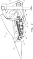
Fig. 2 is an end view of the header shown inFigs. 1 , with some of the sheet metal removed to expose a row unit and chopping unit; -
Fig. 3 is a top view of the header shown inFigs. 1 and2 , with the snouts associated with the row units removed; and -
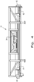
Fig. 4 is a rear view of the header shown inFigs. 1-3 . - Corresponding reference characters indicate corresponding parts throughout the several views. The exemplification set out herein illustrates an embodiment of the invention, in one form, and such exemplification is not to be construed as limiting the scope of the invention in any manner.
- Referring now to the drawings, and more particularly to
Fig. 1 , there is shown anagricultural harvester 10 which generally includes abase unit 12 and an embodiment of aheader 14 of the present disclosure. In the illustrated embodiment,base unit 12 is in the form of a combine with only a portion of afeeder housing 16 being shown for simplicity sake. Thecombine 12 may include a number of conventional systems and sub-systems for threshing, separating, cleaning, etc. It is also to be understood thatagricultural harvester 10 may be configured as a different type of harvester, such as a sugar cane harvester, cotton harvester, forage harvester, etc. -
Header 14 can include aframe 18 supporting a number of structural components. For example, when configured as a corn header as shown inFig. 1 ,header 14 can include a number ofrow units 20 separated bysnouts 22. In the embodiment shown,header 14 is configured as a 12 row corn header. Eachrow unit 20 generally separates the ears of corn from most of the MOG and conveys the ears of corn and some MOG toward the rear ofheader 14, where it is conveyed laterally inward towardfeeder housing 16 using a doublepitch cross auger 24. The ears of corn and MOG can then transported intocombine 12 for further threshing, separating and cleaning. - Referring now to
Figs. 2 and3 , eachrow unit 20 can include a feed/snappingunit 26 which together define a first sub-system ofheader 14. Each feed/snapping unit 26 can include a pair ofgathering chains 28,stripper plates 30 andstalk rolls 32. As thecombine 12 moves in a forward travel direction while harvesting, thegathering chains 28 move the corn stalks (not shown) in a rearward direction in the space betweenstripper plates 30. As the stalks move rearwardly, the stalk rolls 32 pull the stalks in a downward direction and as the ears of corn on the stalks hit thestripper plates 30, the ears are stripped from the stalk and lie on top of thestripper plates 30. Thegathering chains 28 then move the ears of corn and some MOG in a rearward direction toward thecross auger 24. - Positioned below each feed/snapping
unit 26 can also be achopping unit 34 which together define a second sub-system ofheader 14. As the corn stalks are stripped downwardly through thestripper plates 30 by the stalk rolls 32, the choppingunits 34 chop the stalks, leaves, etc. (MOG) into finer pieces which are then distributed onto the field. Eachchopping unit 34 is associated with at least onerespective row unit 20 and includes one ormore cutting blades 36. In the illustrated embodiment, eachchopping unit 34 includes a pair of cuttingblades 36 which rotate at a desired rotational speed providing a desired cutting tip speed (velocity) at the outermost end of each blade. The illustratedchopping units 34, for example, have a desired or target rotational speed of approximately 2800 RPM. - According to an aspect of the present application, multiple input drives are provided on the
header 14 corresponding to the number of sub-systems which are separately driven on header 14 (Figs. 1-4 ). As indicated above, in the embodiment ofheader 14 shown and described herein, a first sub-system is assumed to correspond to the plurality of feed/snappingunits 26 and a second sub-system is assumed to correspond to the plurality of choppingunits 34. The sub-systemsonboard header 14 which are to be separately driven can also be differently configured, such as a cutter bar and/or reel on a bean header, etc. - More particularly,
header 14 can include afirst input drive 40 and asecond input drive 42 which may each be mechanically coupled with corresponding output drives (not specifically shown) carried bycombine 12.First input drive 40 andsecond input drive 42 may each be coupled with the corresponding output drives oncombine 12 using any suitable coupling structure, such as a telescoping power take off (PTO) shaft or other suitable coupler.Header 14 is shown with thefirst input drive 40 being located at one end (left) of theheader 14 and thesecond input drive 42 being located at an opposite end (right) of theheader 14, on opposite sides offeeder housing 16. However, the orientation of thefirst input drive 40 andsecond input drive 42 can be switched, or both input drives 40 and 42 can be located on the same side of thefeeder housing 16. Moreover, more than two input drives can also be provided. - First input drive 40 can be configured as an input drive shaft which is coupled with a
common drive shaft 44 which extends acrossheader 14 and mechanically drives each of the feed/snappingunits 26 at a first operating speed (Fig. 2 ). Suitable gears, belts, pulleys, etc within ahousing 46 at the left end ofheader 14 can be used to interconnect thefirst input drive 40 withcommon drive shaft 44. The operating speed of feed/snappingunits 26 can be variable to accommodate varying field conditions during harvesting. For example,header 14 can include a controllable component used to control the operating speed of feed/snappingunits 26, such as a continuously variable transmission (CVT), different sized chain drive sprockets, belt drive pulleys, interchangeable gears to modify drive ratios, a shiftable planetary gear set, etc. Alternatively, the operating speed of the output shaft fromcombine 12 which drives thefirst input drive 40 can be varied, while the output shaft fromcombine 12 which drives thesecond input drive 42 can be maintaining substantially constant. This results in the drive for the choppingunits 34 and feed/snappingunits 26 being split onboard thecombine 12 rather than theheader 14. - Second input drive 42 can likewise be configured as an input drive shaft which is coupled with a
common drive shaft 48 which extends acrossheader 14 and mechanically drives each of the choppingunits 34 at a second operating speed (Fig. 2 ). Suitable gears, belts, pulleys, etc within ahousing 50 at the right end ofheader 14 can be used to interconnect thesecond input drive 42 withcommon drive shaft 48. Eachchopping unit 34 can be operated at a desired operating speed to provide adequate cutting of the MOG conveyed downwardly by an associated feed/snappingunit 26. Accordingly, eachchopping unit 34 can be operated at a constant operating speed which is independent of the rotational speed of the feed/snapping units 26. Thesecond input drive 42 is set at a desired constant operating speed, and effective cutting of the MOG always occurs regardless of the selected variable operating speed of the feed/snapping units 26. The phrase "constant operating speed" as used in this disclosure is meant to be the selected speed at which the choppingunits 34 operate, by way of thesecond input drive 42, which can vary through operator input by up to +/- 20% (e.g., by throttling up or throttling down the internal combustion engine, or maintaining a rated engine speed and adjusting the output speed of the output drive shaft from the base unit). Once set by the operator, the choppingunits 34 then operate at a corresponding substantially constant operating speed. - At a rated operating (PTO) speed of
combine 12, the choppingunits 34 can be configured to be incapable of being adjusted by an operator. Using asecond input drive 42 as described above, and with thecombine 12 operating at the rated PTO speed, thesecond input drive 42 has no provisions which would allow the operator to adjust the operating speed of the choppingunits 34. In this manner, the choppingunits 34 always have a predetermined blade tip operating speed to ensure that the crop material is adequately chopped prior to being returned to the ground. In the embodiment described above, the choppingunits 34 are driven in a direct drive manner by thesecond input drive 42 that is driven at a constant operating speed from thecombine 12. Neither thecombine 12 nor theheader 14 has any adjustment feature that would allow the rotational speed of the choppingunits 34 to be adjusted. - In the embodiment shown and described above, the combine includes two output shafts which drive a
first input drive 40 andsecond input drive 42 onboard theheader 14. However, in another embodiment (not shown), it is also possible to use a single output shaft from thecombine 12 which drives both thefirst input drive 40 andsecond input drive 42 onboard theheader 14. For example, a single output shaft from thecombine 12 can directly drive the second input drive 40 associated with the choppingunits 34, and a gearbox or the like in the driveline can split the rotational power in a parallel manner to drive the second input drive 42 associated with the feed/snapping units 26. A CVT or other suitable controllable component as described above can be used to vary the operating speed of the feed/snapping units 26. In the case of a combine having two output shafts, the first and second input drives 40 and 42 are directly coupled with the combine, whereas in the case of a combine having a single output shaft, thefirst input drive 40 would be directly coupled with the combine and thesecond input drive 42 would be indirectly coupled with the combine by way of thefirst input drive 40. - In another embodiment, such as a smaller corn header (e.g., a 6 row header), it might not be cost effective to run separate output shafts from the combine, with two separate input drives on the header to the chopping units and to the row units. The smaller headers are more likely to be used with a combine having a fixed speed feeder drive and again it would not be cost effective to add a variable speed unit to the row unit drive. One possibility on such a header might be to run a series configuration from the combine, to the chopper units, and then to the feed/snapping units, with a manual adjustment for the operator to adjust the speed of the feed/snapping units. For example, the combine can have a single output shaft which would connect to one end of the header (e.g., right end). From the right end, the drive shaft for the chopping units would extend across to the other end of the header (e.g., left end) and operate at a fixed speed for the chopping units. Then from the other end of the header, this drive shaft would connect with another drive shaft extending across the header for the feed/snapping units. A manually adjustable component, such as chain drive with changeable sprockets or a small gearbox with a 2 or 3 speed ratio could be placed on the header between the two drive shafts, accessible to an operator. Configured as such, the chopping units would always run at a constant speed and the operator could manually change the row unit speed by changing a sprocket or gear level on the end of the header. This would eliminate the need for two input drives on the smaller headers.
Claims (5)
- A header (14) for an agricultural harvester (10), comprising:a plurality of row units;a plurality of feed/snapping units (26), each said feed/snapping unit (26) being associated with a respective said row unit and operable at a first operating speed;a first input drive couplable with a base unit (12) of the harvester (10) said first input drive including a first input drive shaft (40) and being connected with a first common drive shaft (44, 48) extending across said header (14) and coupled with each said feed/snapping unit (26); anda plurality of chopping units (34), each said chopping unit (34) being associated with at least one respective said feed/snapping unit (26) and operable at a constant second operating speed, independent of said first operating speed,characterized in that the header (14) further comprises:a second input drive couplable with the base unit (12) of the harvester (10), said second input drive including a second input drive shaft (42) and being connected with a second common drive shaft (44, 48) extending across said header (14) and coupled with each said chopping unit (34) .
- The header (14) of claim 1, wherein said first operating speed is a variable operating speed.
- The header (14) of claim 1, wherein said first input drive (40) shaft is located toward one end of said header (14), and said second input drive (42) shaft is located toward an opposite end of said header (14).
- An agricultural harvester (10), comprising:a base unit (12); anda header (14) as claimed in any one of the preceding claims.
- The agricultural harvester (10) of claim 4, wherein the base unit (12) includes a feeder housing, and the header (14) further includes a first input drive (40) coupled with the base unit (12) and a second input drive (42) coupled with the base unit (12), said first input drive (40) being positioned on one side of said feeder housing and said second input drive (42) being positioned on an opposite side of said feeder housing.
Applications Claiming Priority (1)
| Application Number | Priority Date | Filing Date | Title |
|---|---|---|---|
| US14/259,464 US9578804B2 (en) | 2014-04-23 | 2014-04-23 | Header for an agricultural harvester with independent sub-system drives |
Publications (2)
| Publication Number | Publication Date |
|---|---|
| EP2936963A1 EP2936963A1 (en) | 2015-10-28 |
| EP2936963B1 true EP2936963B1 (en) | 2017-06-14 |
Family
ID=52997935
Family Applications (1)
| Application Number | Title | Priority Date | Filing Date |
|---|---|---|---|
| EP15164632.0A Active EP2936963B1 (en) | 2014-04-23 | 2015-04-22 | Header for an agricultural harvester with independent sub-system drives |
Country Status (4)
| Country | Link |
|---|---|
| US (2) | US9578804B2 (en) |
| EP (1) | EP2936963B1 (en) |
| CN (1) | CN104996087B (en) |
| BR (1) | BR102015008973B1 (en) |
Cited By (2)
| Publication number | Priority date | Publication date | Assignee | Title |
|---|---|---|---|---|
| DE102023120836A1 (en) | 2023-08-06 | 2025-02-06 | Claas Industrietechnik Gmbh | corn picker and agricultural machinery equipped with it |
| DE102023120835A1 (en) | 2023-08-06 | 2025-02-06 | Claas Industrietechnik Gmbh | corn picker and agricultural machinery equipped with it |
Families Citing this family (21)
| Publication number | Priority date | Publication date | Assignee | Title |
|---|---|---|---|---|
| US9578804B2 (en) * | 2014-04-23 | 2017-02-28 | Cnh Industrial America Llc | Header for an agricultural harvester with independent sub-system drives |
| DE102015115100A1 (en) * | 2015-09-08 | 2017-03-09 | Carl Geringhoff Gmbh & Co. Kg | Device for harvesting stalky stalks |
| US10130035B2 (en) * | 2015-11-10 | 2018-11-20 | Cnh Industrial America Llc | Row unit for a corn head assembly having a top plate with a structured surface |
| DE102017207337A1 (en) * | 2016-07-20 | 2018-01-25 | Deere & Company | Mulching device for processing plant stumps standing on a field |
| US10123482B2 (en) * | 2016-07-20 | 2018-11-13 | Cnh Industrial America Llc | Corn header having an air flow generating cutting blade for an agricultural harvester |
| EP3556197B1 (en) | 2018-04-17 | 2021-03-24 | CNH Industrial Belgium NV | Header with multiple row elements |
| US10694671B2 (en) * | 2018-04-19 | 2020-06-30 | Cnh Industrial America Llc | Header with multiple row elements |
| US11064653B2 (en) | 2018-06-18 | 2021-07-20 | Ag Leader Technology | Agricultural systems having stalk sensors and data visualization systems and related devices and methods |
| DE102018215616A1 (en) * | 2018-09-13 | 2020-03-19 | Deere & Company | Arrangement for controlling the height and / or inclination of a header for harvesting stalk-like crop |
| WO2020101993A1 (en) * | 2018-11-16 | 2020-05-22 | Cnh Industrial America Llc | Harvester header with lateral belt roller mount |
| US11553648B2 (en) * | 2019-04-29 | 2023-01-17 | Deere And Company | Corn stalk roll drive system |
| US12495736B2 (en) | 2019-09-04 | 2025-12-16 | Ag Leader Technology | Apparatus, systems and methods for stalk sensing |
| CN110684753A (en) * | 2019-11-14 | 2020-01-14 | 中国科学院东北地理与农业生态研究所 | Application of Soybean Cuticle Wax Synthesis Gene or Its Protein |
| US11758848B2 (en) | 2020-04-08 | 2023-09-19 | Ag Leader Technology | Devices, systems, and methods for sensing the cross-sectional area of stalks |
| US12414505B2 (en) * | 2020-09-04 | 2025-09-16 | Ag Leader Technology | Harvesting system for row-by-row control of a harvester |
| EP4070642B1 (en) * | 2021-04-08 | 2024-02-28 | Maschinenfabrik Kemper GmbH & Co. KG | Attachment for harvesting stalk-like plants with a picking gap transverse to the direction of travel |
| US12279556B2 (en) * | 2021-07-26 | 2025-04-22 | Cnh Industrial America Llc | Dual variable feeder drive for agricultural vehicle |
| US12453311B2 (en) * | 2022-06-06 | 2025-10-28 | Cnh Industrial America Llc | Electric row unit drive system for corn header of combine harvester |
| US12471530B2 (en) | 2022-07-29 | 2025-11-18 | Cnh Industrial America Llc | Variable speed stalk roll unit |
| US20240122110A1 (en) * | 2022-10-14 | 2024-04-18 | Cnh Industrial America Llc | Systems and methods to adjust operation of an agricultural system |
| US20250133998A1 (en) * | 2023-10-31 | 2025-05-01 | Deere & Company | Systems and methods for changing a speed of a belt drive system |
Family Cites Families (43)
| Publication number | Priority date | Publication date | Assignee | Title |
|---|---|---|---|---|
| US2418575A (en) * | 1944-07-06 | 1947-04-08 | Christiansen Christian | Beet harvester |
| US2442520A (en) * | 1945-07-09 | 1948-06-01 | Papec Machine Company | Row crop silage harvester |
| US3808783A (en) * | 1972-06-07 | 1974-05-07 | Deere & Co | Soybean harvesting header |
| US3961466A (en) * | 1974-01-30 | 1976-06-08 | Gehl Company | Crop feeding attachment for forage choppers |
| US4115983A (en) * | 1974-08-19 | 1978-09-26 | Deere & Company | Row-crop harvesting header |
| US4251980A (en) * | 1979-03-26 | 1981-02-24 | Miller Kent A | Cornstalk harvesting and windrow attachment for a corn picker header |
| US4227366A (en) * | 1979-08-06 | 1980-10-14 | Sperry Corporation | Corn header drive system |
| US4269017A (en) * | 1979-09-11 | 1981-05-26 | Deere & Company | Harvester header with a main frame of modular subframes |
| US4419856A (en) * | 1980-12-08 | 1983-12-13 | Taylor Clyde L | Seed harvesting apparatus |
| US4434606A (en) * | 1982-05-04 | 1984-03-06 | Superior Gear Box Company | Gear box for corn harvesting unit |
| US5330114A (en) * | 1993-05-28 | 1994-07-19 | Trenkamp Michael J | Shredder attachment for combine corn head |
| DE29702902U1 (en) * | 1997-02-19 | 1998-06-18 | Maschinenfabrik Kemper GmbH, 48703 Stadtlohn | Machine for row-independent mowing of maize and the like stem-like crop |
| US5921070A (en) | 1997-06-13 | 1999-07-13 | Fmc Corporation | Corn head with variable knife and gathering belt speed |
| US5927054A (en) | 1997-06-13 | 1999-07-27 | Fmc Corporation | Corn head with variable angle harvesting |
| DE19730912C2 (en) * | 1997-07-18 | 2000-02-10 | Ludger Wiegert | Device for harvesting corn |
| US6119442A (en) | 1999-05-14 | 2000-09-19 | Case Corporation | Combine setting autoadjust with machine vision |
| US6370853B1 (en) * | 1999-10-13 | 2002-04-16 | Case Corporation | Drive system for corn header row units |
| DE19959281A1 (en) * | 1999-12-09 | 2001-06-13 | Kemper Gmbh Maschf | Feeding and picking device of a crop recovery device |
| DE19959282A1 (en) * | 1999-12-09 | 2001-06-13 | Kemper Gmbh Maschf | Feeding and picking device with chopping device |
| US6516599B1 (en) | 1999-12-10 | 2003-02-11 | David Clarke | Corn harvester with improved ear picking mechanism |
| GB0101557D0 (en) * | 2001-01-22 | 2001-03-07 | Ford New Holland Nv | Drive mechanism for a front attachment of an agricultural harvesting machine and corresponding front attachment |
| DE10220699A1 (en) | 2002-05-10 | 2003-12-24 | Deere & Co | Device for adjusting the cutting length of a chopping device |
| DE10257776A1 (en) * | 2002-12-11 | 2004-06-24 | Maschinenfabrik Kemper Gmbh & Co. Kg | Feeding and picking device |
| DE102004029953A1 (en) * | 2004-06-21 | 2006-01-12 | Deere & Company, Moline | Header drive |
| DE602004011373T2 (en) | 2004-12-18 | 2008-07-03 | Deere & Company, Moline | harvester |
| US7694500B2 (en) * | 2006-02-17 | 2010-04-13 | Deere & Company | Drive assembly and drive system for a combine head |
| DE102006025455A1 (en) * | 2006-05-30 | 2007-12-20 | Claas Saulgau Gmbh | Attachment for harvesting stemmed crops |
| HU229564B1 (en) | 2007-01-26 | 2014-02-28 | Optigep Kft | Harvest adapter equipped with stalk crusher for cereals, mainly for sunflower |
| US7739861B2 (en) * | 2008-01-29 | 2010-06-22 | Deere & Company | Corn head clutch monitor |
| DE102009051053A1 (en) * | 2009-05-28 | 2010-12-02 | Claas Selbstfahrende Erntemaschinen Gmbh | Attachment for harvesting stalk-shaped plants |
| US7874134B1 (en) * | 2009-07-17 | 2011-01-25 | Deere & Company | Converting a corn head row unit for harvesting corn stalks in addition to ears |
| CN201690790U (en) * | 2010-04-04 | 2011-01-05 | 山东五征集团有限公司 | Corn picking device with straw chopping and stubble cleaning functions |
| DE102010036306A1 (en) * | 2010-07-09 | 2012-02-02 | Claas Selbstfahrende Erntemaschinen Gmbh | Maispflücker |
| WO2012024462A1 (en) * | 2010-08-19 | 2012-02-23 | Agco Corporation | Tilting crop stalk chopper |
| US7937918B1 (en) * | 2010-08-27 | 2011-05-10 | Deere & Company | Drive arrangement for corn head equipped with or without a corn stalk chopper |
| DE102010051887A1 (en) * | 2010-11-22 | 2012-05-24 | Carl Geringhoff Gmbh & Co. Kg | Attachment for harvesting stalky stalks |
| DE102012014087A1 (en) * | 2012-07-16 | 2014-01-16 | Franz Schrattenecker | Picking unit, header and harvester for maize or the like |
| DE102012014081A1 (en) | 2012-07-16 | 2014-01-16 | Franz Schrattenecker | Picking unit, header and harvester for maize or the like |
| DE102012014085A1 (en) * | 2012-07-16 | 2014-01-16 | Franz Schrattenecker | Picking unit, header and harvester for maize or the like |
| DE102012106603A1 (en) * | 2012-07-20 | 2014-05-15 | Claas Hungaria Kft. | Series independent attachment for harvesting stemmed crops |
| DE102012106602A1 (en) * | 2012-07-20 | 2014-05-15 | Claas Hungaria Kft. | Attachment for harvesting corn |
| CN202941154U (en) * | 2012-11-30 | 2013-05-22 | 郑州中联收获机械有限公司 | Corn harvester and header thereof |
| US9578804B2 (en) * | 2014-04-23 | 2017-02-28 | Cnh Industrial America Llc | Header for an agricultural harvester with independent sub-system drives |
-
2014
- 2014-04-23 US US14/259,464 patent/US9578804B2/en active Active
-
2015
- 2015-04-21 BR BR102015008973-2A patent/BR102015008973B1/en active IP Right Grant
- 2015-04-22 EP EP15164632.0A patent/EP2936963B1/en active Active
- 2015-04-23 CN CN201510196577.9A patent/CN104996087B/en not_active Expired - Fee Related
-
2017
- 2017-01-17 US US15/407,967 patent/US10327386B2/en active Active
Cited By (4)
| Publication number | Priority date | Publication date | Assignee | Title |
|---|---|---|---|---|
| DE102023120836A1 (en) | 2023-08-06 | 2025-02-06 | Claas Industrietechnik Gmbh | corn picker and agricultural machinery equipped with it |
| DE102023120835A1 (en) | 2023-08-06 | 2025-02-06 | Claas Industrietechnik Gmbh | corn picker and agricultural machinery equipped with it |
| EP4505860A1 (en) | 2023-08-06 | 2025-02-12 | CLAAS Industrietechnik GmbH | Corn header and agricultural machine equipped with same |
| EP4505859A1 (en) | 2023-08-06 | 2025-02-12 | CLAAS Industrietechnik GmbH | Corn header and agricultural machine equipped with same |
Also Published As
| Publication number | Publication date |
|---|---|
| US10327386B2 (en) | 2019-06-25 |
| BR102015008973B1 (en) | 2020-06-16 |
| CN104996087A (en) | 2015-10-28 |
| US20150305240A1 (en) | 2015-10-29 |
| CN104996087B (en) | 2019-10-08 |
| US9578804B2 (en) | 2017-02-28 |
| EP2936963A1 (en) | 2015-10-28 |
| US20170118916A1 (en) | 2017-05-04 |
| BR102015008973A2 (en) | 2015-12-15 |
Similar Documents
| Publication | Publication Date | Title |
|---|---|---|
| US10327386B2 (en) | Header for an agricultural harvester with independent sub-system drives | |
| EP3440918B1 (en) | Foldable corn head | |
| US9198351B2 (en) | Front attachment for harvesting corn including a drive mechanism with a steplessly variable transmission | |
| RU2661403C2 (en) | Self-propelled combine harvester drive system in designed as belt transmission | |
| US20160073585A1 (en) | Power takeoff drive assembly for a corn header of an agricultural harvester | |
| EP3153006A1 (en) | Non-row sensitive threshing corn header | |
| US4148175A (en) | Corn stalk harvester and windrow attachment for a corn picker header | |
| US9848537B2 (en) | Drive system for combine harvester processor | |
| EP3530103B1 (en) | Drive unit for a down crop attachment on a header | |
| JP5102636B2 (en) | Combine | |
| EP3516945B1 (en) | Down crop attachment for a header | |
| EP3603378B1 (en) | Conveyor chain with multi-segment conveying floor | |
| US12538871B2 (en) | Drive system for combine harvester processor | |
| EP3277071B1 (en) | Drive system for combine harvester processor and method of providing such | |
| US12279556B2 (en) | Dual variable feeder drive for agricultural vehicle | |
| EP4595742A1 (en) | Variable speed drive for chaff mill of combine harvester | |
| UA123437C2 (en) | Device for harvesting stalk-like stem crops |
Legal Events
| Date | Code | Title | Description |
|---|---|---|---|
| PUAI | Public reference made under article 153(3) epc to a published international application that has entered the european phase |
Free format text: ORIGINAL CODE: 0009012 |
|
| AK | Designated contracting states |
Kind code of ref document: A1 Designated state(s): AL AT BE BG CH CY CZ DE DK EE ES FI FR GB GR HR HU IE IS IT LI LT LU LV MC MK MT NL NO PL PT RO RS SE SI SK SM TR |
|
| AX | Request for extension of the european patent |
Extension state: BA ME |
|
| 17P | Request for examination filed |
Effective date: 20160428 |
|
| RBV | Designated contracting states (corrected) |
Designated state(s): AL AT BE BG CH CY CZ DE DK EE ES FI FR GB GR HR HU IE IS IT LI LT LU LV MC MK MT NL NO PL PT RO RS SE SI SK SM TR |
|
| GRAP | Despatch of communication of intention to grant a patent |
Free format text: ORIGINAL CODE: EPIDOSNIGR1 |
|
| STAA | Information on the status of an ep patent application or granted ep patent |
Free format text: STATUS: GRANT OF PATENT IS INTENDED |
|
| RIC1 | Information provided on ipc code assigned before grant |
Ipc: A01D 45/02 20060101AFI20161115BHEP |
|
| INTG | Intention to grant announced |
Effective date: 20161212 |
|
| GRAS | Grant fee paid |
Free format text: ORIGINAL CODE: EPIDOSNIGR3 |
|
| GRAA | (expected) grant |
Free format text: ORIGINAL CODE: 0009210 |
|
| STAA | Information on the status of an ep patent application or granted ep patent |
Free format text: STATUS: THE PATENT HAS BEEN GRANTED |
|
| AK | Designated contracting states |
Kind code of ref document: B1 Designated state(s): AL AT BE BG CH CY CZ DE DK EE ES FI FR GB GR HR HU IE IS IT LI LT LU LV MC MK MT NL NO PL PT RO RS SE SI SK SM TR |
|
| REG | Reference to a national code |
Ref country code: GB Ref legal event code: FG4D |
|
| REG | Reference to a national code |
Ref country code: CH Ref legal event code: EP Ref country code: AT Ref legal event code: REF Ref document number: 900110 Country of ref document: AT Kind code of ref document: T Effective date: 20170615 |
|
| REG | Reference to a national code |
Ref country code: IE Ref legal event code: FG4D |
|
| REG | Reference to a national code |
Ref country code: DE Ref legal event code: R096 Ref document number: 602015003068 Country of ref document: DE |
|
| REG | Reference to a national code |
Ref country code: NL Ref legal event code: MP Effective date: 20170614 |
|
| REG | Reference to a national code |
Ref country code: LT Ref legal event code: MG4D |
|
| PG25 | Lapsed in a contracting state [announced via postgrant information from national office to epo] |
Ref country code: FI Free format text: LAPSE BECAUSE OF FAILURE TO SUBMIT A TRANSLATION OF THE DESCRIPTION OR TO PAY THE FEE WITHIN THE PRESCRIBED TIME-LIMIT Effective date: 20170614 Ref country code: HR Free format text: LAPSE BECAUSE OF FAILURE TO SUBMIT A TRANSLATION OF THE DESCRIPTION OR TO PAY THE FEE WITHIN THE PRESCRIBED TIME-LIMIT Effective date: 20170614 Ref country code: LT Free format text: LAPSE BECAUSE OF FAILURE TO SUBMIT A TRANSLATION OF THE DESCRIPTION OR TO PAY THE FEE WITHIN THE PRESCRIBED TIME-LIMIT Effective date: 20170614 Ref country code: GR Free format text: LAPSE BECAUSE OF FAILURE TO SUBMIT A TRANSLATION OF THE DESCRIPTION OR TO PAY THE FEE WITHIN THE PRESCRIBED TIME-LIMIT Effective date: 20170915 Ref country code: NO Free format text: LAPSE BECAUSE OF FAILURE TO SUBMIT A TRANSLATION OF THE DESCRIPTION OR TO PAY THE FEE WITHIN THE PRESCRIBED TIME-LIMIT Effective date: 20170914 |
|
| REG | Reference to a national code |
Ref country code: AT Ref legal event code: MK05 Ref document number: 900110 Country of ref document: AT Kind code of ref document: T Effective date: 20170614 |
|
| PG25 | Lapsed in a contracting state [announced via postgrant information from national office to epo] |
Ref country code: BG Free format text: LAPSE BECAUSE OF FAILURE TO SUBMIT A TRANSLATION OF THE DESCRIPTION OR TO PAY THE FEE WITHIN THE PRESCRIBED TIME-LIMIT Effective date: 20170914 Ref country code: SE Free format text: LAPSE BECAUSE OF FAILURE TO SUBMIT A TRANSLATION OF THE DESCRIPTION OR TO PAY THE FEE WITHIN THE PRESCRIBED TIME-LIMIT Effective date: 20170614 Ref country code: LV Free format text: LAPSE BECAUSE OF FAILURE TO SUBMIT A TRANSLATION OF THE DESCRIPTION OR TO PAY THE FEE WITHIN THE PRESCRIBED TIME-LIMIT Effective date: 20170614 Ref country code: RS Free format text: LAPSE BECAUSE OF FAILURE TO SUBMIT A TRANSLATION OF THE DESCRIPTION OR TO PAY THE FEE WITHIN THE PRESCRIBED TIME-LIMIT Effective date: 20170614 Ref country code: NL Free format text: LAPSE BECAUSE OF FAILURE TO SUBMIT A TRANSLATION OF THE DESCRIPTION OR TO PAY THE FEE WITHIN THE PRESCRIBED TIME-LIMIT Effective date: 20170614 |
|
| PG25 | Lapsed in a contracting state [announced via postgrant information from national office to epo] |
Ref country code: AT Free format text: LAPSE BECAUSE OF FAILURE TO SUBMIT A TRANSLATION OF THE DESCRIPTION OR TO PAY THE FEE WITHIN THE PRESCRIBED TIME-LIMIT Effective date: 20170614 Ref country code: SK Free format text: LAPSE BECAUSE OF FAILURE TO SUBMIT A TRANSLATION OF THE DESCRIPTION OR TO PAY THE FEE WITHIN THE PRESCRIBED TIME-LIMIT Effective date: 20170614 Ref country code: RO Free format text: LAPSE BECAUSE OF FAILURE TO SUBMIT A TRANSLATION OF THE DESCRIPTION OR TO PAY THE FEE WITHIN THE PRESCRIBED TIME-LIMIT Effective date: 20170614 Ref country code: EE Free format text: LAPSE BECAUSE OF FAILURE TO SUBMIT A TRANSLATION OF THE DESCRIPTION OR TO PAY THE FEE WITHIN THE PRESCRIBED TIME-LIMIT Effective date: 20170614 Ref country code: CZ Free format text: LAPSE BECAUSE OF FAILURE TO SUBMIT A TRANSLATION OF THE DESCRIPTION OR TO PAY THE FEE WITHIN THE PRESCRIBED TIME-LIMIT Effective date: 20170614 |
|
| PG25 | Lapsed in a contracting state [announced via postgrant information from national office to epo] |
Ref country code: ES Free format text: LAPSE BECAUSE OF FAILURE TO SUBMIT A TRANSLATION OF THE DESCRIPTION OR TO PAY THE FEE WITHIN THE PRESCRIBED TIME-LIMIT Effective date: 20170614 Ref country code: SM Free format text: LAPSE BECAUSE OF FAILURE TO SUBMIT A TRANSLATION OF THE DESCRIPTION OR TO PAY THE FEE WITHIN THE PRESCRIBED TIME-LIMIT Effective date: 20170614 Ref country code: IS Free format text: LAPSE BECAUSE OF FAILURE TO SUBMIT A TRANSLATION OF THE DESCRIPTION OR TO PAY THE FEE WITHIN THE PRESCRIBED TIME-LIMIT Effective date: 20171014 Ref country code: PL Free format text: LAPSE BECAUSE OF FAILURE TO SUBMIT A TRANSLATION OF THE DESCRIPTION OR TO PAY THE FEE WITHIN THE PRESCRIBED TIME-LIMIT Effective date: 20170614 |
|
| REG | Reference to a national code |
Ref country code: DE Ref legal event code: R097 Ref document number: 602015003068 Country of ref document: DE |
|
| REG | Reference to a national code |
Ref country code: FR Ref legal event code: PLFP Year of fee payment: 4 |
|
| PLBE | No opposition filed within time limit |
Free format text: ORIGINAL CODE: 0009261 |
|
| STAA | Information on the status of an ep patent application or granted ep patent |
Free format text: STATUS: NO OPPOSITION FILED WITHIN TIME LIMIT |
|
| PG25 | Lapsed in a contracting state [announced via postgrant information from national office to epo] |
Ref country code: DK Free format text: LAPSE BECAUSE OF FAILURE TO SUBMIT A TRANSLATION OF THE DESCRIPTION OR TO PAY THE FEE WITHIN THE PRESCRIBED TIME-LIMIT Effective date: 20170614 |
|
| 26N | No opposition filed |
Effective date: 20180315 |
|
| PG25 | Lapsed in a contracting state [announced via postgrant information from national office to epo] |
Ref country code: SI Free format text: LAPSE BECAUSE OF FAILURE TO SUBMIT A TRANSLATION OF THE DESCRIPTION OR TO PAY THE FEE WITHIN THE PRESCRIBED TIME-LIMIT Effective date: 20170614 |
|
| PG25 | Lapsed in a contracting state [announced via postgrant information from national office to epo] |
Ref country code: MC Free format text: LAPSE BECAUSE OF FAILURE TO SUBMIT A TRANSLATION OF THE DESCRIPTION OR TO PAY THE FEE WITHIN THE PRESCRIBED TIME-LIMIT Effective date: 20170614 |
|
| REG | Reference to a national code |
Ref country code: CH Ref legal event code: PL |
|
| REG | Reference to a national code |
Ref country code: BE Ref legal event code: MM Effective date: 20180430 |
|
| REG | Reference to a national code |
Ref country code: IE Ref legal event code: MM4A |
|
| PG25 | Lapsed in a contracting state [announced via postgrant information from national office to epo] |
Ref country code: LU Free format text: LAPSE BECAUSE OF NON-PAYMENT OF DUE FEES Effective date: 20180422 |
|
| PG25 | Lapsed in a contracting state [announced via postgrant information from national office to epo] |
Ref country code: BE Free format text: LAPSE BECAUSE OF NON-PAYMENT OF DUE FEES Effective date: 20180430 Ref country code: CH Free format text: LAPSE BECAUSE OF NON-PAYMENT OF DUE FEES Effective date: 20180430 Ref country code: LI Free format text: LAPSE BECAUSE OF NON-PAYMENT OF DUE FEES Effective date: 20180430 |
|
| PG25 | Lapsed in a contracting state [announced via postgrant information from national office to epo] |
Ref country code: IE Free format text: LAPSE BECAUSE OF NON-PAYMENT OF DUE FEES Effective date: 20180422 |
|
| PG25 | Lapsed in a contracting state [announced via postgrant information from national office to epo] |
Ref country code: MT Free format text: LAPSE BECAUSE OF NON-PAYMENT OF DUE FEES Effective date: 20180422 |
|
| PG25 | Lapsed in a contracting state [announced via postgrant information from national office to epo] |
Ref country code: TR Free format text: LAPSE BECAUSE OF FAILURE TO SUBMIT A TRANSLATION OF THE DESCRIPTION OR TO PAY THE FEE WITHIN THE PRESCRIBED TIME-LIMIT Effective date: 20170614 |
|
| PG25 | Lapsed in a contracting state [announced via postgrant information from national office to epo] |
Ref country code: PT Free format text: LAPSE BECAUSE OF FAILURE TO SUBMIT A TRANSLATION OF THE DESCRIPTION OR TO PAY THE FEE WITHIN THE PRESCRIBED TIME-LIMIT Effective date: 20170614 |
|
| PG25 | Lapsed in a contracting state [announced via postgrant information from national office to epo] |
Ref country code: MK Free format text: LAPSE BECAUSE OF NON-PAYMENT OF DUE FEES Effective date: 20170614 Ref country code: CY Free format text: LAPSE BECAUSE OF FAILURE TO SUBMIT A TRANSLATION OF THE DESCRIPTION OR TO PAY THE FEE WITHIN THE PRESCRIBED TIME-LIMIT Effective date: 20170614 Ref country code: HU Free format text: LAPSE BECAUSE OF FAILURE TO SUBMIT A TRANSLATION OF THE DESCRIPTION OR TO PAY THE FEE WITHIN THE PRESCRIBED TIME-LIMIT; INVALID AB INITIO Effective date: 20150422 |
|
| REG | Reference to a national code |
Ref country code: DE Ref legal event code: R082 Ref document number: 602015003068 Country of ref document: DE Representative=s name: MEISSNER BOLTE PATENTANWAELTE RECHTSANWAELTE P, DE |
|
| PG25 | Lapsed in a contracting state [announced via postgrant information from national office to epo] |
Ref country code: AL Free format text: LAPSE BECAUSE OF FAILURE TO SUBMIT A TRANSLATION OF THE DESCRIPTION OR TO PAY THE FEE WITHIN THE PRESCRIBED TIME-LIMIT Effective date: 20170614 |
|
| PGFP | Annual fee paid to national office [announced via postgrant information from national office to epo] |
Ref country code: IT Payment date: 20230413 Year of fee payment: 9 |
|
| PGFP | Annual fee paid to national office [announced via postgrant information from national office to epo] |
Ref country code: GB Payment date: 20230420 Year of fee payment: 9 |
|
| GBPC | Gb: european patent ceased through non-payment of renewal fee |
Effective date: 20240422 |
|
| PG25 | Lapsed in a contracting state [announced via postgrant information from national office to epo] |
Ref country code: GB Free format text: LAPSE BECAUSE OF NON-PAYMENT OF DUE FEES Effective date: 20240422 |
|
| PG25 | Lapsed in a contracting state [announced via postgrant information from national office to epo] |
Ref country code: GB Free format text: LAPSE BECAUSE OF NON-PAYMENT OF DUE FEES Effective date: 20240422 |
|
| PG25 | Lapsed in a contracting state [announced via postgrant information from national office to epo] |
Ref country code: IT Free format text: LAPSE BECAUSE OF NON-PAYMENT OF DUE FEES Effective date: 20240422 |
|
| PGFP | Annual fee paid to national office [announced via postgrant information from national office to epo] |
Ref country code: DE Payment date: 20250428 Year of fee payment: 11 |
|
| PGFP | Annual fee paid to national office [announced via postgrant information from national office to epo] |
Ref country code: FR Payment date: 20250424 Year of fee payment: 11 |