EP2938389B1 - Récipient de transport - Google Patents
Récipient de transport Download PDFInfo
- Publication number
- EP2938389B1 EP2938389B1 EP13867862.8A EP13867862A EP2938389B1 EP 2938389 B1 EP2938389 B1 EP 2938389B1 EP 13867862 A EP13867862 A EP 13867862A EP 2938389 B1 EP2938389 B1 EP 2938389B1
- Authority
- EP
- European Patent Office
- Prior art keywords
- base
- cap
- shield
- radiation
- container
- Prior art date
- Legal status (The legal status is an assumption and is not a legal conclusion. Google has not performed a legal analysis and makes no representation as to the accuracy of the status listed.)
- Not-in-force
Links
- 239000012530 fluid Substances 0.000 claims description 24
- 239000000463 material Substances 0.000 claims description 19
- 239000000758 substrate Substances 0.000 claims description 18
- 239000012217 radiopharmaceutical Substances 0.000 claims description 12
- 229940121896 radiopharmaceutical Drugs 0.000 claims description 11
- 230000002799 radiopharmaceutical effect Effects 0.000 claims description 11
- 230000013011 mating Effects 0.000 claims description 7
- 238000004891 communication Methods 0.000 claims description 6
- 230000001681 protective effect Effects 0.000 claims description 2
- 230000005855 radiation Effects 0.000 description 10
- 238000004519 manufacturing process Methods 0.000 description 9
- 230000000694 effects Effects 0.000 description 8
- 230000002285 radioactive effect Effects 0.000 description 6
- 238000000605 extraction Methods 0.000 description 4
- 238000003780 insertion Methods 0.000 description 3
- 230000037431 insertion Effects 0.000 description 3
- 238000012986 modification Methods 0.000 description 3
- 230000004048 modification Effects 0.000 description 3
- 241001631457 Cannula Species 0.000 description 2
- 238000011109 contamination Methods 0.000 description 2
- 238000004806 packaging method and process Methods 0.000 description 2
- 230000003252 repetitive effect Effects 0.000 description 2
- 239000002250 absorbent Substances 0.000 description 1
- 230000002745 absorbent Effects 0.000 description 1
- 229910052787 antimony Inorganic materials 0.000 description 1
- WATWJIUSRGPENY-UHFFFAOYSA-N antimony atom Chemical compound [Sb] WATWJIUSRGPENY-UHFFFAOYSA-N 0.000 description 1
- 238000013459 approach Methods 0.000 description 1
- 239000011248 coating agent Substances 0.000 description 1
- 238000000576 coating method Methods 0.000 description 1
- 238000013461 design Methods 0.000 description 1
- 239000003814 drug Substances 0.000 description 1
- 229940126534 drug product Drugs 0.000 description 1
- 230000005294 ferromagnetic effect Effects 0.000 description 1
- 239000011521 glass Substances 0.000 description 1
- 238000002347 injection Methods 0.000 description 1
- 239000007924 injection Substances 0.000 description 1
- 239000000825 pharmaceutical preparation Substances 0.000 description 1
- 230000035939 shock Effects 0.000 description 1
- 239000007787 solid Substances 0.000 description 1
- 230000000087 stabilizing effect Effects 0.000 description 1
- 239000012780 transparent material Substances 0.000 description 1
- 239000011800 void material Substances 0.000 description 1
Images


Classifications
-
- G—PHYSICS
- G21—NUCLEAR PHYSICS; NUCLEAR ENGINEERING
- G21F—PROTECTION AGAINST X-RADIATION, GAMMA RADIATION, CORPUSCULAR RADIATION OR PARTICLE BOMBARDMENT; TREATING RADIOACTIVELY CONTAMINATED MATERIAL; DECONTAMINATION ARRANGEMENTS THEREFOR
- G21F5/00—Transportable or portable shielded containers
- G21F5/015—Transportable or portable shielded containers for storing radioactive sources, e.g. source carriers for irradiation units; Radioisotope containers
-
- A—HUMAN NECESSITIES
- A61—MEDICAL OR VETERINARY SCIENCE; HYGIENE
- A61J—CONTAINERS SPECIALLY ADAPTED FOR MEDICAL OR PHARMACEUTICAL PURPOSES; DEVICES OR METHODS SPECIALLY ADAPTED FOR BRINGING PHARMACEUTICAL PRODUCTS INTO PARTICULAR PHYSICAL OR ADMINISTERING FORMS; DEVICES FOR ADMINISTERING FOOD OR MEDICINES ORALLY; BABY COMFORTERS; DEVICES FOR RECEIVING SPITTLE
- A61J1/00—Containers specially adapted for medical or pharmaceutical purposes
- A61J1/14—Details; Accessories therefor
- A61J1/16—Holders for containers
-
- G—PHYSICS
- G21—NUCLEAR PHYSICS; NUCLEAR ENGINEERING
- G21F—PROTECTION AGAINST X-RADIATION, GAMMA RADIATION, CORPUSCULAR RADIATION OR PARTICLE BOMBARDMENT; TREATING RADIOACTIVELY CONTAMINATED MATERIAL; DECONTAMINATION ARRANGEMENTS THEREFOR
- G21F5/00—Transportable or portable shielded containers
- G21F5/06—Details of, or accessories to, the containers
- G21F5/12—Closures for containers; Sealing arrangements
Definitions
- the present invention relates to the field of containers. More specifically, the present invention is directed to a shielded container for a radiopharmaceutical.
- Radio-pharmaceuticals are typically packaged in a standard way to reduce exposure to the end-user of the product. Most of these types of pharmaceuticals have short half-lives, so radioactive content can be extremely high to the operators during manufacturing and handling of these products.
- Packaging containers consists of several components, with the main component being lead. Lead has a very high density and provides excellent shielding characteristics for both gamma and beta emitting radio-pharmaceuticals. Lead is also very heavy and thus contributes to ergonomically related stress during manufacturing, assembly, and handling.
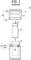
- a radio-pharmaceutical container 10 of the prior art typically includes an outer shell 12 that is typically formed from plastic and is both durable and cleanable.
- the outer shell 12 is durable to meet the requirements of the Department of Transportation (DOT).
- DOT Department of Transportation
- the outer shell 12 must contain and protect the inner contents of the package 10 during shipping and use of the product.
- the outer shell 12 is cleanable so that any radioactive contamination can be washed off of the surface. Radioactive contamination is a possibility due to the nature of the contents and the environment where the containers are used.
- the outer shell 12 typically has a label containing all of the product information such as; product name, manufacturing date, volume, specific activity, etc.
- the outer shell 12 is usually and injection molded component that contains sub-parts 12a and 12b that are assembled into a lower and upper assembly.
- Container 10 further includes an inner shell 14 that fits within the outer shell 12.
- the inner shell 14 is typically manufactured from lead with a small percentage of antimony.
- the inner shell is designed to provide shielding of the radioactive contents of the container 10.
- the inner shell 14 is usually poured from molten lead into a negative void, or form.
- the inner shell 14 contains sub-parts 14a and 14b that are assembled into a cap 16 and base 18 by mating with outer shell sup-parts 12a and 12b, respectively.
- the prior art container accommodates a product container 15, typically a vial, that is the primary holder of the product. It can be made of plastic or glass and can be sterile or non-sterile.
- Container 15 typically includes a pierceable septum across an open end, or mouth, thereof. Septum 17 allows a needle or cannula to pierce the septum and extend to the product fluid contained within container 15 for withdrawal.
- the product container 15 may be kept in the shipping container 10 during use to reduce exposure to the end-user.
- an absorbent material placed in the container to absorb fluid if the product container is breached during shipment or use.
- a cushioning material such as a sponge, to protect the product container from shock during shipment or use.
- an inner sleeve that can be between an inner surface and the product container to segregate the product container from the lead of the radiation shield.
- the outer shell 12 and inner shell 14 are fully formed by a mating cap 16 and base 18.
- the base 18 typically defines the container cavity 20 into which the vial 15 is placed.
- the product container typically a vial
- the cap 16 is placed into the container cavity 20 and the cap 16 is secured to the base 18.
- the cap 16 is removed and a syringe is used to pierce the septum 17 of the vial 15 for extraction of the desired amount of product fluid.
- Manipulation of the fluid requires the cap 16 to be removed, thus providing the path for radiation exposure to a user.
- These packaging containers provide shielding from the activity of the radiopharmaceutical within during shipment and storage. However, once the container is opened, there can be exposure to both lead as well as to radiation shining out through the open storage cavity of the inner shell. Additionally, once the container is opened, the product container 15 is loose, or non-captive. Moreover, in order to visually check the amount of radioactive fluid remaining in the vial 15, an operator must lift the vial 15 out from cavity 20, further exposing the operator to activity shining out from the vial.
- US5274239 A provides a shielded dose calibration apparatus configured such that the collection vial need never be removed from its protective shield to be calibrated.
- US20100019174 A1 provides a radiation-shielding container for a radiopharmaceutical that may be magnetically picked and placed, which minimizes operator exposure during manufacture, assembly and handling of the container.
- the art lacks a shielded container for a radiopharmaceutical which reduces operator exposure to the radiopharmaceutical during extraction of the radiopharmaceutical product and extraction of the product vial.
- the present invention provides a radiation-shielding transportation and storage container for a radiopharmaceutical, as defined in claim 1, which provides protection to the clinician, or operator, who must extract the fluid from the vial within the container.
- the present invention may be assembled to provide a sealed, radiation-shielded, lead-safe, container useful for storage, transportation, and extraction of the product fluid.
- the present invention is intended to substantially minimize or eliminate lead exposure to the operator, reduce whole-body and extremity exposure for the clinician, and safely and stably hold the product vial therein.
- the container includes an outer cap, a base, and an inner cap.
- the inner cap includes an inner cap shield cylindrical portion defining an open end and an inner cap aperture and an opposed planar wall.
- the inner cap shield includes an outer surface and an inner surface whereby the inner surface helps define a cavity and the inner shield defines at least one aperture therethrough. When assembled the at least one aperture is in fluid communication with the cavity.
- the base includes an elongate cylindrical base shield having an open end defining a base aperture and an opposed closed end.
- the base shield includes an outer base shield surface and an inner base shield surface whereby the inner base shield surface defines a lower base cavity in fluid communication with the at least one aperture through the inner cap shield.
- the container of the present invention includes a removable base portion which allows the vial to be dropped from the cavity, away from the inner cap shield, so that the clinician may view the amount of fluid remaining in the vial.
- the present invention further includes a cylindrical inner shield having a longitudinal gap, the gap allowing the clinician to see the fluid within the vial, while the shield offers protection to the clinician from exposure to the activity of the fluid.
- the provision of a removable base portion allows for the inner shield to be formed as a unitary component with the remainder of the base shield.
- the container may further includes a ferromagnetic plug positioned adjacent to an outer surface of the shield of one of the cap shield and the base shield to assist in automated pick and placement of the container.
- the container of the present invention reduces the ergonomic and repetitive stress associated to the manufacture and handling of the product as the removable cap for product withdrawal does not include a full radiation-shielding liner as with the caps of the prior art.
- the product container of the present invention can weigh one pound or more, and a typical manufacturing lot may contain several hundred to several thousand product containers.
- the size of the container of the present invention is such that single hand manipulation of the product container is common; however, the size is several inches in diameter and ergonomically challenging when handling production volumes.
- the container of the present invention will minimize the operator whole body and extremity exposure incurred during manufacturing and handling of the product.
- the container of the present invention will reduce the ergonomic and repetitive stress associated with the manufacturing and handling of the product.
- a product vial may be placed within the cavity of the container of the present invention so that the end-user will receive a needle-accessible vial in the container.
- the container includes a pierceable septum or stopper.
- the cooperating shields of the inner cap and base will substantially surround the vial so that only the inner cap aperture(s), or passageway(s), provide a shine path for the activity out of the product cavity.
- the shielding substrate of the outer cap will be in overlying shielding registry with the inner cap passageways, thus completing the shielding of the activity within the product cavity.
- the inner cap With the product vial inserted into the product cavity, the inner cap may then be connected to the base such that the septum of the vial is thus placed in underlying registry with the passesway(s) of the inner cap.
- the passageway(s) of the inner cap are desirably formed to conform to the outer dimensions of a withdrawal or vent needle inserted therethrough, as appropriate, the present invention will provide minimal exposure of a clinician to the activity of the product fluid within the cavity, particularly as compared to the container of the prior art, when inserting the needles through the inner cap.
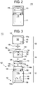
- the present invention provides a radiation-shielding container 110 including a base 111, an outer cap 113, and an inner cap 115.
- Outer cap 113 includes an outer cap body 150 defining an outer cap cavity 152 and a shielding substrate 154 formed from a radiation-shielding material.
- Outer cap body 150 is desirably formed from a polymeric material.
- Base 111 and inner cap 115 are removably connectable to each other.
- Base 111 and inner cap 115 further include cooperating radiation shields members 112 and 118 which define a product cavity 116 therebetween for receiving a product container 15 therein.
- the radiation shield 112 of the inner cap 115 defines at least one elongate aperture, or passageway, 120 therethrough.
- passageway(s) are shown to extend parallel to the longitudinal axis of the container, the present invention contemplates that the passageways may extend obliquely through the inner cap shield 112, and while the obliquely-oriented passageways may still be in effective registry with the shielding substrate of the outer cap 113, such passageway(s) could necessitate providing additional shielding material in the outer cap. That is, outer cap 113 is contemplated to support a shielding layer that extends in overlying shielding registry with the apertures extending through radiation shield 112 so as to shield the shine path thus presented.
- Base 111 and outer cap 113 are also removably connectable to each other such that when inner cap 115 is connected to base 111, inner cap 115 will be contained within outer cap cavity 152 and the at least one passageway of the inner cap extends in fluid communication through the radiation shield of the inner cap between the product cavity and outer cap cavity 152.
- outer cap 113 includes a cylindrical wall 170 perimetrically bounding and depending from a planar end wall 172 so as to define cavity 152.
- Walls 170 and 172 are desirably formed from a polymeric material.
- Shielding substrate 154 may be adhered to an inner surface 172a of wall 172 by a bonding layer 156, such as a polymeric tape or other substrate which bonds to surface 172a in a manner to hold shielding substrate 154 in place.
- Inner surface 172a may further define a recess 175 (not shown) into which shielding substrate 154 is supported.
- Shielding substrate 154 being formed from a radiation-shielding material, is held in overlying shielding registry with the aperture(s) extending through inner cap 115 when the outer cap and the inner cap are both connected to the base.
- the present invention contemplates that shielding substrate 154 is coextensive with any shine path extending through the apertures of inner cap 115. If necessary, the present invention contemplates that shielding substrate 154 may extend along the cylindrical wall 170 if necessary to block the shine path from inner cap 115 extending through the polyemeric material of outer cap 113 unattenuated.
- the present invention contemplates for all embodiments that the shielding substrate 154 or its associated bonding layer 156 comes to rest on inner cap 115 so as to close off apertures 136 and 138, ie, there need not be a gap therebetween providing communication between cavity 116 and cavity 152.
- Apertures 136 and 138 will be used herein to refer to the passageways formed through inner cap 115 for all embodiments, while apertures 120 may specifically refer to the passageway(s) through the inner cap shield.
- the dimensions of substrate 154 will thus be dictated by the material used, the orientation of the apertures through inner cap 115, and the amount of shielding desired given the activity of the product to be held within the container.
- Container 110 provides an inner cap shield 112 spanning the mouth 114 (not shown) of the lower cavity 116a of the base shield 118.
- the inner cap shield 112 and base shield 118 provide shielding material which defines the base cavity 116.
- the inner cap shield 112 further provides a first aperture 120 therethrough which allow the insertion of a withdrawal cannula, or needle, 125 therethrough to pierce the septum 17 of an inserted vial 15.
- the inner cap 112 may also provide a second aperture 122 therethrough which will allow the insertion of a second cannula, or needle, 135 therethrough to pierce the septum 17 of a vial 15 held in cavity 116 and assist in fluid withdrawal as is known in the art.
- any aperture formed through the inner cap is sized and shaped to substantially conform to the cannula or needle inserted therethrough.
- Container 110 further includes an inner cap cover 130 having a cylindrical wall 132 perimetrically bounding and descending from a planar end wall 134.
- Planar end wall 134 defines first and second apertures 136 and 138 therethrough which are positioned in overlying shielding registry with apertures 120 and 122 of inner cap shield 112.
- End wall 134 desirably also includes depending cylindrical walls 140 and 142 which further define apertures 136 and 138 and which are sized and shaped to provide a lining along apertures 120 and 122 so that the cannulas inserted therethrough do not contact the shielding material of cap shield 112.
- Cylindrical wall 132 further defines inner cover cavity 144 which receives cap shield 112.
- the present invention contemplates that cylindrical wall 132 extends along a portion 146a of the outer surface 146 of base shield 118.
- Base 111 includes an elongate cylindrical base shield 118 having a cylindrical wall 160 extending between opposed first and second ends 162 and 164, respectively.
- First end of wall 160 defines open mouth 114 in fluid communication with lower cavity 116a opposite a substantially planar wall 165 at second end 164.
- Base shield 118 includes an outer base shield surface 146 and an inner base shield surface 148 about lower cavity 116a.
- a polymeric base covering 145 (not shown) is provided about outer surface 146 below portion 146a although it is further contemplated that covering 145 may extend the full length of surface 146 is if wall 132 is modified to so accommodate.
- the present invention further contemplates surface 148 further supports a thin cylindrical polymeric liner 190 thereon to extend between shield 118 and a container 15 within cavity 116.
- Liner 190 desirably also includes a planar portion 190a covering the inner surface 165a of planar wall 165.
- a polymeric liner 192 may also be positioned on an interior surface 112a of radiation shield 112 of the inner cap 115 such that no radiation-shielding material of the inner cap is exposed to the product container 15.
- first polymeric liner may be provided completely about the radiation shield of the base and a second polymeric liner may be provided completely about the radiation shield of the inner cap such that no radiation-shielding material of the inner cap or the base is exposed when said inner cap is removably connected to said base.
- the present invention contemplates that the outer cap body 150 and base 111 include cooperating members to removably connect the outer cap body 150 to the base 111.
- the cooperating members may take the form of, by way of illustration and not of limitation, helical threads or cooperating bayonet connectors as represented by parts 180 and 182 in Figure 3 .
- Inner cap 115 and base 111 may also include cooperating elements to removably connect the inner cap 115 to the base 111.
- the cooperating elements may take the form of, by way of illustration and not of limitation, cooperating helical threads or cooperating deflectable detents, or the cooperating slot and pin 184 and 186 depicted in Figure 3 .
- the present invention may further provide a compressible cushion within the product cavity further protect the vial during storage and transportation.
- the cushion may be sized to accommodate a vial of a particular size by deflecting just enough so that the vial is held captive between the cushion and the inner cap, further stabilizing the vial within the product cavity so as to minimize breakage of the vial.
- the present invention may eliminate the need to provide labels to both the vial and to the transportation container. A label on the transportation container may be sufficient for the clinician.
- a container may further contemplate that the base of the container may also include a removably attachable base wall.
- the removable base wall provides for a 'bottom entry' of the vial into the product cavity. Base wall would thus function as a bottom cap for the container.
- the base wall may define a portion of a cavity 116 which holds the vial 15 inserted in the product cavity. Once vial 15 is inserted into cavity 116, the clinician will be able to direct needles 125 and 135 through apertures 136 and 138 to withdraw the fluid contents from vial 15.
- FIGS. 5 and 6 depict a radiation-shielding container 210.
- Container 210 is desirably identical to container 110, with like numbering reflecting like components, except for the modifications to accommodate the removable base portion as herein described.
- Container 210 includes a base 111, an upper cap 113, and inner cap 115. Additionally, base 111 includes removable base portion, or lower cap, 117. That is, for container 210, base shield 118 is a two-piece component as is base cover 145.
- base 111 includes a cylindrical shield portion 118' and separable planar end wall portion 165'.
- Cover 145 includes a first portion 145a covering outer surface 146 of cylindrical shield portion 118' and a second portion 145b about outer surface 165b of end wall 165.
- Portions 145a and 145b include mating components 187 and 188, such as mating helical threads or bayonet connectors which allow for end wall portion 165' to be removably attached to cylindrical shield portion 118'. It will be understood that any interior liner 190 would likewise include a first portion 190a provided along surface 148 and a second portion 190b covering surface 165a as shown in Figure 5 . Figure 6 does not depict the polymeric liners of Figure 5 , for clarity of the exploded view.
- upper cap 113 provides a shielding substrate 154 to be affixed to an inner surface 172a thereof.
- Shielding substrate 154 extends in overlying shielding registry with apertures 136 and 138 formed in shield 112 of inner cap 115 so as to guard against a shine path through those apertures from the product in container 15.
- Apertures 136 and 138 provide for insertion of cannulas 125 and 135 for withdrawing the product fluid from container 15 in cavity 166.
- this example also contemplates, as best shown in Figure 6 , providing a semi-cylindrical wall 194 about container 15 within cavity 166 which extends substantially around the circumference of the vial.
- the semi-cylindrical wall 194 is desirably formed from a radiation-shielding material which itself is desirably coated with a polymeric coating (not shown) to protect a user handling wall 194.
- the semi-cylindrical wall provides an elongate gap 195 along the length of the vial which will allow a clinician the ability to visually confirm the amount of fluid within the vial. Alternatively, the gap may allow a user to confirm information provided on a label attached to the vial.
- semi-cylindrical wall 194 is affixed to base wall along a lower edge 194a so that the clinician may handle the rest of container 210 with one hand and the lower cap 117 with the other hand when removing the lower cap 117 from base 111 so as to inspect the product vial.
- semi-cylindrical wall may be affixed to shield 112, so that a clinician could inspect the vial by removing inner cap 115 from base 111.
- This example also desirably includes a solid floor spanning lower edge 194a so as to hold vial 15 while the clinician lifts cap 115 and shield 194 from cavity 166.
- the thickness of the radiation shielding material in the semi-cylindrical wall 194, and the dimensions for container 210 may thus be selected according to the needs of the clinicians for a particular radioactive product fluid.
- Figure 7 depict another container 310 in which the inner cap shield is formed as a unitary piece with the cylindrical shield portion of the base shield while the planar base shield wall is detachable. That is, container 310 is a modification to container 210 in which shield 112 is formed as one piece with cylindrical shield portion 118' to form a unitary base shield.
- base 111 may be said to define apertures 136 and 138 such that shielding substrate 154 of cap 113 is in overlying shielding registry therewith.
- Cavity 116 again provides a product vial 15 therein such that needles 125 and 135 may be inserted through passageways 136 and 138 so as to withdraw fluid from vial 15.
- liners 190a and 192 may also be formed as a unitary liner 390 and cover 145a may be formed with cover 130 as a unitary cover 330.
- Container 310 thus only provides a single entry for a vial 15 into cavity 166 by removing lower cap 117, inserting vial 15 into cavity 166 and then attaching lower cap 117 to the base 111 as described for Figures 5-6 .
Landscapes
- Physics & Mathematics (AREA)
- High Energy & Nuclear Physics (AREA)
- General Engineering & Computer Science (AREA)
- Engineering & Computer Science (AREA)
- Health & Medical Sciences (AREA)
- Animal Behavior & Ethology (AREA)
- Veterinary Medicine (AREA)
- Public Health (AREA)
- General Health & Medical Sciences (AREA)
- Life Sciences & Earth Sciences (AREA)
- Pharmacology & Pharmacy (AREA)
- Medical Preparation Storing Or Oral Administration Devices (AREA)
- Closures For Containers (AREA)
Claims (10)
- Récipient de blindage anti-rayonnement (110) pour stocker et transporter un produit radiopharmaceutique, ledit récipient comprenant :une base (111) comprenant un blindage de base cylindrique allongé (118) ayant une extrémité ouverte (162) définissant une ouverture de base (114) et une extrémité fermée opposée (164), ledit blindage de base (118) comprenant une surface de blindage de base externe (146) et une surface de blindage de base interne (148), ladite surface de blindage de base interne (148) définissant une cavité de base (116, 116a) en communication fluidique avec ladite ouverture de base (114) ;un capuchon externe (113) comprenant une paroi cylindrique allongée (170) ayant une première extrémité ouverte et une extrémité fermée opposée, ledit capuchon externe (113) définissant une cavité de capuchon externe (152), ledit capuchon interne (113) et ladite base (111) comprenant en outre des composants de couplage coopérants (180/182) pour fixer de manière amovible ledit capuchon externe (113) à ladite base (111) ;un capuchon interne (115) comprenant un blindage de capuchon interne (112) et un couvercle de blindage (130), ledit blindage de capuchon interne (112) étant formé d'un matériau de blindage anti-rayonnement et comprenant une paroi de blindage interne cylindrique allongée (132) ayant une première et une seconde extrémité opposées, ladite première extrémité de ladite paroi de blindage définissant une ouverture de blindage de capuchon interne (120, 122) et ladite seconde extrémité comprenant une paroi d'extrémité planaire (134) couvrant ladite paroi de blindage interne cylindrique (132), ladite paroi d'extrémité (134) comprenant des première et seconde surfaces sensiblement planaires opposées, dans lequel ladite paroi d'extrémité (134) définit au moins un passage ouvert allongé (144) débouchant sur lesdites première et seconde surfaces planaires ;dans lequel ledit capuchon interne (115) et ladite base (111) comprennent en outre des éléments de couplage coopérants (184/186) pour fixer de manière amovible ledit capuchon interne (115) à ladite base (111) en sorte que ledit capuchon interne (115) soit positionné dans ladite cavité de capuchon externe (152) lorsque ledit capuchon externe (113) et ledit capuchon interne (115) sont fixés à ladite base (111) ; etdans lequel ledit capuchon externe (113) comprend en outre un substrat de blindage planaire (154) formé d'un matériau de blindage anti-rayonnement supporté par ledit capuchon externe (113) en registre de blindage chevauchant avec ledit au moins un passage (144) dudit blindage de capuchon interne (112) lorsque ledit capuchon externe (113) et ledit capuchon interne (115) sont fixés à ladite base (111).
- Récipient de blindage anti-rayonnement (110) selon la revendication 1, dans lequel au moins l'un dudit blindage de capuchon interne (112) et dudit blindage de base (118) supporte une garniture de blindage polymère (190, 192) telle qu'aucun matériau de blindage anti-rayonnement ne soit exposé lorsque le capuchon interne (115) est assemblé à ladite base (111).
- Récipient de blindage anti-rayonnement (110) selon la revendication 1 ou la revendication 2, dans lequel ledit blindage de capuchon interne (112) définit un premier et un second passage allongé (120, 136, 138) qui le traversent.
- Récipient de blindage anti-rayonnement (110) selon l'une quelconque des revendications précédentes, dans lequel ledit blindage de capuchon interne (112) est recouvert par une garniture polymère le long de la surface externe.
- Récipient de blindage anti-rayonnement (110) selon l'une quelconque des revendications précédentes, dans lequel ledit capuchon externe (113) comprend en outre une couche de liaison (156), dans lequel ledit substrat de blindage (154) est fixé entre ledit capuchon externe (113) et ladite couche de liaison (156).
- Récipient de blindage anti-rayonnement (110) selon l'une quelconque des revendications précédentes, dans lequel ledit capuchon externe (113) comprend en outre une paroi d'extrémité planaire (172) à ladite seconde extrémité de ladite paroi de capuchon externe cylindrique (170), ladite paroi d'extrémité (172) définissant une cavité dans laquelle ledit substrat de blindage (154) est supporté.
- Récipient de blindage anti-rayonnement (110) selon l'une quelconque des revendications précédentes, dans lequel à la fois ledit capuchon interne (115) et ladite base (111) comprennent en outre une garniture externe autour de la surface externe de leurs blindages respectifs, lesdites garnitures externes fournissant un engagement de couplage entre ledit capuchon interne (115) et ladite base (111).
- Récipient de blindage anti-rayonnement (110) selon la revendication 7, dans lequel à la fois ledit capuchon interne (115) et ladite base (111) comprennent en outre une garniture interne le long de la surface interne de leurs surfaces de blindage de capuchon respectives.
- Récipient de blindage anti-rayonnement (110) selon la revendication 8, dans lequel ladite garniture interne et ladite garniture externe à la fois dudit capuchon interne (115) et de ladite base (111) encapsulent complètement leurs blindages respectifs.
- Récipient de blindage anti-rayonnement (110) selon l'une quelconque des revendications précédentes, comprenant en outre un coussin déviable supporté dans ladite cavité interne.
Applications Claiming Priority (2)
| Application Number | Priority Date | Filing Date | Title |
|---|---|---|---|
| US201261746195P | 2012-12-27 | 2012-12-27 | |
| PCT/US2013/077840 WO2014105971A1 (fr) | 2012-12-27 | 2013-12-26 | Récipient de transport |
Publications (3)
| Publication Number | Publication Date |
|---|---|
| EP2938389A1 EP2938389A1 (fr) | 2015-11-04 |
| EP2938389A4 EP2938389A4 (fr) | 2016-11-16 |
| EP2938389B1 true EP2938389B1 (fr) | 2018-02-21 |
Family
ID=51022064
Family Applications (1)
| Application Number | Title | Priority Date | Filing Date |
|---|---|---|---|
| EP13867862.8A Not-in-force EP2938389B1 (fr) | 2012-12-27 | 2013-12-26 | Récipient de transport |
Country Status (4)
| Country | Link |
|---|---|
| US (1) | US9324466B2 (fr) |
| EP (1) | EP2938389B1 (fr) |
| CN (1) | CN104870048B (fr) |
| WO (1) | WO2014105971A1 (fr) |
Families Citing this family (17)
| Publication number | Priority date | Publication date | Assignee | Title |
|---|---|---|---|---|
| WO2012092394A1 (fr) | 2010-12-29 | 2012-07-05 | Cardinal Health 414, Llc | Système fermé de remplissage de flacon pour distribution aseptique |
| US20130102772A1 (en) | 2011-07-15 | 2013-04-25 | Cardinal Health 414, Llc | Systems, methods and devices for producing, manufacturing and control of radiopharmaceuticals-full |
| US9417332B2 (en) | 2011-07-15 | 2016-08-16 | Cardinal Health 414, Llc | Radiopharmaceutical CZT sensor and apparatus |
| US20130020727A1 (en) | 2011-07-15 | 2013-01-24 | Cardinal Health 414, Llc. | Modular cassette synthesis unit |
| US9757306B2 (en) * | 2013-03-13 | 2017-09-12 | Bayer Healthcare Llc | Vial container with collar cap |
| US9327886B2 (en) * | 2013-03-13 | 2016-05-03 | Bayer Healthcare Llc | Vial container with collar cap |
| JP6310244B2 (ja) * | 2013-12-06 | 2018-04-11 | 日立造船株式会社 | 放射性物質収納用キャスクの製造方法 |
| US20180085477A1 (en) * | 2015-04-08 | 2018-03-29 | Sonocore, Inc. | Method for manufacturing bubbles |
| CN109313109B (zh) * | 2017-05-09 | 2021-07-06 | 广州非比科技有限公司 | 一种低温生物保存容器 |
| WO2018208576A1 (fr) * | 2017-05-09 | 2018-11-15 | Fibulas, Inc. | Récipient pour la conservation de produits biologiques à basse température |
| CN113559277B (zh) | 2018-01-11 | 2023-11-17 | 比卡生物科技(广州)有限公司 | 一种注射用卡巴他赛组合物及其制备方法 |
| US11224555B2 (en) * | 2018-04-23 | 2022-01-18 | Hospira, Inc. | Access and vapor containment system for a drug vial and method of making and using same |
| CN110797131B (zh) * | 2019-11-08 | 2021-04-09 | 哈尔滨工程大学 | 一种具有可变屏蔽层的集装箱辐射防护装置 |
| CN212434267U (zh) * | 2020-02-04 | 2021-01-29 | 中国海洋石油集团有限公司 | 一种放射性源库 |
| CN120693187A (zh) * | 2022-11-22 | 2025-09-23 | 波士顿科学国际有限公司 | 可注射材料的输送装置、系统和方法 |
| GB2624666A (en) * | 2022-11-25 | 2024-05-29 | Wellnet Ltd | Needle support device and kit for delivery of radiopharmaceutical medicament |
| IT202300014019A1 (it) * | 2023-07-05 | 2025-01-05 | Comecer Spa | Contenitore schermato monouso per un flacone contenente una dose di radiofarmaco |
Family Cites Families (10)
| Publication number | Priority date | Publication date | Assignee | Title |
|---|---|---|---|---|
| US3531644A (en) * | 1967-01-31 | 1970-09-29 | Mallinckrodt Chemical Works | Packaging assembly for radioactive materials |
| JPS5387400U (fr) * | 1977-12-15 | 1978-07-18 | ||
| JPH0524078Y2 (fr) * | 1987-03-11 | 1993-06-18 | ||
| US5274239A (en) * | 1992-07-23 | 1993-12-28 | Sunol Technologies, Inc. | Shielded dose calibration apparatus |
| US5823379A (en) * | 1993-10-20 | 1998-10-20 | Amersham International Plc | Sealed container for hazardous material |
| ITRM20020071A1 (it) * | 2002-02-11 | 2003-08-11 | Sigma Tau Ind Farmaceuti | Contenitore per flacone di radiofarmaco, e corredo per la sua infusione in un paziente o per il suo trasferimento altrove. |
| WO2004032151A2 (fr) * | 2002-10-02 | 2004-04-15 | Mallinckrodt Inc. | Saumon pharmaceutique et procede d'utilisation |
| CA2502436C (fr) * | 2002-10-17 | 2011-12-20 | Mallinckrodt, Inc. | Boitier pharmaceutique polymere et procedes d'utilisation et de production associes |
| WO2008077004A1 (fr) | 2006-12-18 | 2008-06-26 | Medi-Physics, Inc. | Conteneur blindé |
| CN202034066U (zh) * | 2011-03-04 | 2011-11-09 | 上海欣科医药有限公司 | 一种放射防护装置 |
-
2013
- 2013-12-26 WO PCT/US2013/077840 patent/WO2014105971A1/fr not_active Ceased
- 2013-12-26 US US14/651,447 patent/US9324466B2/en not_active Expired - Fee Related
- 2013-12-26 CN CN201380068539.4A patent/CN104870048B/zh not_active Expired - Fee Related
- 2013-12-26 EP EP13867862.8A patent/EP2938389B1/fr not_active Not-in-force
Non-Patent Citations (1)
| Title |
|---|
| None * |
Also Published As
| Publication number | Publication date |
|---|---|
| CN104870048B (zh) | 2018-11-30 |
| CN104870048A (zh) | 2015-08-26 |
| EP2938389A4 (fr) | 2016-11-16 |
| EP2938389A1 (fr) | 2015-11-04 |
| US9324466B2 (en) | 2016-04-26 |
| WO2014105971A1 (fr) | 2014-07-03 |
| US20150325321A1 (en) | 2015-11-12 |
Similar Documents
| Publication | Publication Date | Title |
|---|---|---|
| EP2938389B1 (fr) | Récipient de transport | |
| CA2612461C (fr) | Ensembles de protection contre le rayonnement et procedes d'utilisation de ces derniers | |
| US8044377B2 (en) | Shielded container | |
| US7812322B2 (en) | Radiation-shielding assemblies and methods | |
| CA3050765C (fr) | Lingot de transport de matiere nocive pour l'organisme | |
| US20080210892A1 (en) | Radiation-Shielding Container Having Status-Indicative Labeling System | |
| US11964131B2 (en) | Syringe shield, syringe shipping and administration system, and components therefor |
Legal Events
| Date | Code | Title | Description |
|---|---|---|---|
| PUAI | Public reference made under article 153(3) epc to a published international application that has entered the european phase |
Free format text: ORIGINAL CODE: 0009012 |
|
| 17P | Request for examination filed |
Effective date: 20150727 |
|
| AK | Designated contracting states |
Kind code of ref document: A1 Designated state(s): AL AT BE BG CH CY CZ DE DK EE ES FI FR GB GR HR HU IE IS IT LI LT LU LV MC MK MT NL NO PL PT RO RS SE SI SK SM TR |
|
| AX | Request for extension of the european patent |
Extension state: BA ME |
|
| RIN1 | Information on inventor provided before grant (corrected) |
Inventor name: HELLE, KEVIN M. Inventor name: REED, JAY C. Inventor name: CHISHOLM, ROBERT F. |
|
| DAX | Request for extension of the european patent (deleted) | ||
| REG | Reference to a national code |
Ref country code: DE Ref legal event code: R079 Ref document number: 602013033547 Country of ref document: DE Free format text: PREVIOUS MAIN CLASS: A61M0036080000 Ipc: G21F0005015000 |
|
| A4 | Supplementary search report drawn up and despatched |
Effective date: 20161019 |
|
| RIC1 | Information provided on ipc code assigned before grant |
Ipc: G21F 5/015 20060101AFI20161013BHEP Ipc: G21F 5/12 20060101ALI20161013BHEP |
|
| GRAP | Despatch of communication of intention to grant a patent |
Free format text: ORIGINAL CODE: EPIDOSNIGR1 |
|
| INTG | Intention to grant announced |
Effective date: 20171009 |
|
| GRAS | Grant fee paid |
Free format text: ORIGINAL CODE: EPIDOSNIGR3 |
|
| GRAA | (expected) grant |
Free format text: ORIGINAL CODE: 0009210 |
|
| AK | Designated contracting states |
Kind code of ref document: B1 Designated state(s): AL AT BE BG CH CY CZ DE DK EE ES FI FR GB GR HR HU IE IS IT LI LT LU LV MC MK MT NL NO PL PT RO RS SE SI SK SM TR |
|
| REG | Reference to a national code |
Ref country code: GB Ref legal event code: FG4D |
|
| REG | Reference to a national code |
Ref country code: CH Ref legal event code: EP |
|
| REG | Reference to a national code |
Ref country code: AT Ref legal event code: REF Ref document number: 972542 Country of ref document: AT Kind code of ref document: T Effective date: 20180315 |
|
| REG | Reference to a national code |
Ref country code: IE Ref legal event code: FG4D |
|
| REG | Reference to a national code |
Ref country code: DE Ref legal event code: R096 Ref document number: 602013033547 Country of ref document: DE |
|
| REG | Reference to a national code |
Ref country code: NL Ref legal event code: MP Effective date: 20180221 |
|
| REG | Reference to a national code |
Ref country code: LT Ref legal event code: MG4D |
|
| REG | Reference to a national code |
Ref country code: AT Ref legal event code: MK05 Ref document number: 972542 Country of ref document: AT Kind code of ref document: T Effective date: 20180221 |
|
| PG25 | Lapsed in a contracting state [announced via postgrant information from national office to epo] |
Ref country code: FI Free format text: LAPSE BECAUSE OF FAILURE TO SUBMIT A TRANSLATION OF THE DESCRIPTION OR TO PAY THE FEE WITHIN THE PRESCRIBED TIME-LIMIT Effective date: 20180221 Ref country code: NO Free format text: LAPSE BECAUSE OF FAILURE TO SUBMIT A TRANSLATION OF THE DESCRIPTION OR TO PAY THE FEE WITHIN THE PRESCRIBED TIME-LIMIT Effective date: 20180521 Ref country code: HR Free format text: LAPSE BECAUSE OF FAILURE TO SUBMIT A TRANSLATION OF THE DESCRIPTION OR TO PAY THE FEE WITHIN THE PRESCRIBED TIME-LIMIT Effective date: 20180221 Ref country code: NL Free format text: LAPSE BECAUSE OF FAILURE TO SUBMIT A TRANSLATION OF THE DESCRIPTION OR TO PAY THE FEE WITHIN THE PRESCRIBED TIME-LIMIT Effective date: 20180221 Ref country code: LT Free format text: LAPSE BECAUSE OF FAILURE TO SUBMIT A TRANSLATION OF THE DESCRIPTION OR TO PAY THE FEE WITHIN THE PRESCRIBED TIME-LIMIT Effective date: 20180221 Ref country code: ES Free format text: LAPSE BECAUSE OF FAILURE TO SUBMIT A TRANSLATION OF THE DESCRIPTION OR TO PAY THE FEE WITHIN THE PRESCRIBED TIME-LIMIT Effective date: 20180221 Ref country code: CY Free format text: LAPSE BECAUSE OF FAILURE TO SUBMIT A TRANSLATION OF THE DESCRIPTION OR TO PAY THE FEE WITHIN THE PRESCRIBED TIME-LIMIT Effective date: 20180221 |
|
| PG25 | Lapsed in a contracting state [announced via postgrant information from national office to epo] |
Ref country code: BG Free format text: LAPSE BECAUSE OF FAILURE TO SUBMIT A TRANSLATION OF THE DESCRIPTION OR TO PAY THE FEE WITHIN THE PRESCRIBED TIME-LIMIT Effective date: 20180521 Ref country code: GR Free format text: LAPSE BECAUSE OF FAILURE TO SUBMIT A TRANSLATION OF THE DESCRIPTION OR TO PAY THE FEE WITHIN THE PRESCRIBED TIME-LIMIT Effective date: 20180522 Ref country code: LV Free format text: LAPSE BECAUSE OF FAILURE TO SUBMIT A TRANSLATION OF THE DESCRIPTION OR TO PAY THE FEE WITHIN THE PRESCRIBED TIME-LIMIT Effective date: 20180221 Ref country code: SE Free format text: LAPSE BECAUSE OF FAILURE TO SUBMIT A TRANSLATION OF THE DESCRIPTION OR TO PAY THE FEE WITHIN THE PRESCRIBED TIME-LIMIT Effective date: 20180221 Ref country code: RS Free format text: LAPSE BECAUSE OF FAILURE TO SUBMIT A TRANSLATION OF THE DESCRIPTION OR TO PAY THE FEE WITHIN THE PRESCRIBED TIME-LIMIT Effective date: 20180221 Ref country code: AT Free format text: LAPSE BECAUSE OF FAILURE TO SUBMIT A TRANSLATION OF THE DESCRIPTION OR TO PAY THE FEE WITHIN THE PRESCRIBED TIME-LIMIT Effective date: 20180221 |
|
| PG25 | Lapsed in a contracting state [announced via postgrant information from national office to epo] |
Ref country code: PL Free format text: LAPSE BECAUSE OF FAILURE TO SUBMIT A TRANSLATION OF THE DESCRIPTION OR TO PAY THE FEE WITHIN THE PRESCRIBED TIME-LIMIT Effective date: 20180221 Ref country code: EE Free format text: LAPSE BECAUSE OF FAILURE TO SUBMIT A TRANSLATION OF THE DESCRIPTION OR TO PAY THE FEE WITHIN THE PRESCRIBED TIME-LIMIT Effective date: 20180221 Ref country code: IT Free format text: LAPSE BECAUSE OF FAILURE TO SUBMIT A TRANSLATION OF THE DESCRIPTION OR TO PAY THE FEE WITHIN THE PRESCRIBED TIME-LIMIT Effective date: 20180221 Ref country code: AL Free format text: LAPSE BECAUSE OF FAILURE TO SUBMIT A TRANSLATION OF THE DESCRIPTION OR TO PAY THE FEE WITHIN THE PRESCRIBED TIME-LIMIT Effective date: 20180221 Ref country code: RO Free format text: LAPSE BECAUSE OF FAILURE TO SUBMIT A TRANSLATION OF THE DESCRIPTION OR TO PAY THE FEE WITHIN THE PRESCRIBED TIME-LIMIT Effective date: 20180221 |
|
| REG | Reference to a national code |
Ref country code: DE Ref legal event code: R097 Ref document number: 602013033547 Country of ref document: DE |
|
| PG25 | Lapsed in a contracting state [announced via postgrant information from national office to epo] |
Ref country code: CZ Free format text: LAPSE BECAUSE OF FAILURE TO SUBMIT A TRANSLATION OF THE DESCRIPTION OR TO PAY THE FEE WITHIN THE PRESCRIBED TIME-LIMIT Effective date: 20180221 Ref country code: SM Free format text: LAPSE BECAUSE OF FAILURE TO SUBMIT A TRANSLATION OF THE DESCRIPTION OR TO PAY THE FEE WITHIN THE PRESCRIBED TIME-LIMIT Effective date: 20180221 Ref country code: SK Free format text: LAPSE BECAUSE OF FAILURE TO SUBMIT A TRANSLATION OF THE DESCRIPTION OR TO PAY THE FEE WITHIN THE PRESCRIBED TIME-LIMIT Effective date: 20180221 Ref country code: DK Free format text: LAPSE BECAUSE OF FAILURE TO SUBMIT A TRANSLATION OF THE DESCRIPTION OR TO PAY THE FEE WITHIN THE PRESCRIBED TIME-LIMIT Effective date: 20180221 |
|
| PLBE | No opposition filed within time limit |
Free format text: ORIGINAL CODE: 0009261 |
|
| STAA | Information on the status of an ep patent application or granted ep patent |
Free format text: STATUS: NO OPPOSITION FILED WITHIN TIME LIMIT |
|
| 26N | No opposition filed |
Effective date: 20181122 |
|
| PG25 | Lapsed in a contracting state [announced via postgrant information from national office to epo] |
Ref country code: SI Free format text: LAPSE BECAUSE OF FAILURE TO SUBMIT A TRANSLATION OF THE DESCRIPTION OR TO PAY THE FEE WITHIN THE PRESCRIBED TIME-LIMIT Effective date: 20180221 |
|
| REG | Reference to a national code |
Ref country code: CH Ref legal event code: PL |
|
| PG25 | Lapsed in a contracting state [announced via postgrant information from national office to epo] |
Ref country code: MC Free format text: LAPSE BECAUSE OF FAILURE TO SUBMIT A TRANSLATION OF THE DESCRIPTION OR TO PAY THE FEE WITHIN THE PRESCRIBED TIME-LIMIT Effective date: 20180221 Ref country code: LU Free format text: LAPSE BECAUSE OF NON-PAYMENT OF DUE FEES Effective date: 20181226 |
|
| REG | Reference to a national code |
Ref country code: IE Ref legal event code: MM4A |
|
| REG | Reference to a national code |
Ref country code: BE Ref legal event code: MM Effective date: 20181231 |
|
| PG25 | Lapsed in a contracting state [announced via postgrant information from national office to epo] |
Ref country code: IE Free format text: LAPSE BECAUSE OF NON-PAYMENT OF DUE FEES Effective date: 20181226 |
|
| PG25 | Lapsed in a contracting state [announced via postgrant information from national office to epo] |
Ref country code: BE Free format text: LAPSE BECAUSE OF NON-PAYMENT OF DUE FEES Effective date: 20181231 |
|
| PG25 | Lapsed in a contracting state [announced via postgrant information from national office to epo] |
Ref country code: CH Free format text: LAPSE BECAUSE OF NON-PAYMENT OF DUE FEES Effective date: 20181231 Ref country code: LI Free format text: LAPSE BECAUSE OF NON-PAYMENT OF DUE FEES Effective date: 20181231 |
|
| PG25 | Lapsed in a contracting state [announced via postgrant information from national office to epo] |
Ref country code: MT Free format text: LAPSE BECAUSE OF NON-PAYMENT OF DUE FEES Effective date: 20181226 |
|
| PGFP | Annual fee paid to national office [announced via postgrant information from national office to epo] |
Ref country code: DE Payment date: 20191119 Year of fee payment: 7 |
|
| PGFP | Annual fee paid to national office [announced via postgrant information from national office to epo] |
Ref country code: FR Payment date: 20191120 Year of fee payment: 7 |
|
| PG25 | Lapsed in a contracting state [announced via postgrant information from national office to epo] |
Ref country code: TR Free format text: LAPSE BECAUSE OF FAILURE TO SUBMIT A TRANSLATION OF THE DESCRIPTION OR TO PAY THE FEE WITHIN THE PRESCRIBED TIME-LIMIT Effective date: 20180221 |
|
| PGFP | Annual fee paid to national office [announced via postgrant information from national office to epo] |
Ref country code: GB Payment date: 20191122 Year of fee payment: 7 |
|
| PG25 | Lapsed in a contracting state [announced via postgrant information from national office to epo] |
Ref country code: PT Free format text: LAPSE BECAUSE OF FAILURE TO SUBMIT A TRANSLATION OF THE DESCRIPTION OR TO PAY THE FEE WITHIN THE PRESCRIBED TIME-LIMIT Effective date: 20180221 |
|
| PG25 | Lapsed in a contracting state [announced via postgrant information from national office to epo] |
Ref country code: HU Free format text: LAPSE BECAUSE OF FAILURE TO SUBMIT A TRANSLATION OF THE DESCRIPTION OR TO PAY THE FEE WITHIN THE PRESCRIBED TIME-LIMIT; INVALID AB INITIO Effective date: 20131226 Ref country code: MK Free format text: LAPSE BECAUSE OF NON-PAYMENT OF DUE FEES Effective date: 20180221 |
|
| PG25 | Lapsed in a contracting state [announced via postgrant information from national office to epo] |
Ref country code: IS Free format text: LAPSE BECAUSE OF FAILURE TO SUBMIT A TRANSLATION OF THE DESCRIPTION OR TO PAY THE FEE WITHIN THE PRESCRIBED TIME-LIMIT Effective date: 20180621 |
|
| REG | Reference to a national code |
Ref country code: DE Ref legal event code: R119 Ref document number: 602013033547 Country of ref document: DE |
|
| GBPC | Gb: european patent ceased through non-payment of renewal fee |
Effective date: 20201226 |
|
| PG25 | Lapsed in a contracting state [announced via postgrant information from national office to epo] |
Ref country code: FR Free format text: LAPSE BECAUSE OF NON-PAYMENT OF DUE FEES Effective date: 20201231 |
|
| PG25 | Lapsed in a contracting state [announced via postgrant information from national office to epo] |
Ref country code: GB Free format text: LAPSE BECAUSE OF NON-PAYMENT OF DUE FEES Effective date: 20201226 Ref country code: DE Free format text: LAPSE BECAUSE OF NON-PAYMENT OF DUE FEES Effective date: 20210701 |