EP2945033B1 - Procédé destiné à définir un processus dans un système de manipulation de liquide - Google Patents
Procédé destiné à définir un processus dans un système de manipulation de liquide Download PDFInfo
- Publication number
- EP2945033B1 EP2945033B1 EP14168144.5A EP14168144A EP2945033B1 EP 2945033 B1 EP2945033 B1 EP 2945033B1 EP 14168144 A EP14168144 A EP 14168144A EP 2945033 B1 EP2945033 B1 EP 2945033B1
- Authority
- EP
- European Patent Office
- Prior art keywords
- formula
- user
- substeps
- parameters
- liquid
- Prior art date
- Legal status (The legal status is an assumption and is not a legal conclusion. Google has not performed a legal analysis and makes no representation as to the accuracy of the status listed.)
- Active
Links
Images






Classifications
-
- G—PHYSICS
- G05—CONTROLLING; REGULATING
- G05D—SYSTEMS FOR CONTROLLING OR REGULATING NON-ELECTRIC VARIABLES
- G05D7/00—Control of flow
- G05D7/06—Control of flow characterised by the use of electric means
- G05D7/0617—Control of flow characterised by the use of electric means specially adapted for fluid materials
- G05D7/0623—Control of flow characterised by the use of electric means specially adapted for fluid materials characterised by the set value given to the control element
-
- G—PHYSICS
- G05—CONTROLLING; REGULATING
- G05B—CONTROL OR REGULATING SYSTEMS IN GENERAL; FUNCTIONAL ELEMENTS OF SUCH SYSTEMS; MONITORING OR TESTING ARRANGEMENTS FOR SUCH SYSTEMS OR ELEMENTS
- G05B19/00—Program-control systems
- G05B19/02—Program-control systems electric
- G05B19/18—Numerical control [NC], i.e. automatically operating machines, in particular machine tools, e.g. in a manufacturing environment, so as to execute positioning, movement or co-ordinated operations by means of program data in numerical form
- G05B19/409—Numerical control [NC], i.e. automatically operating machines, in particular machine tools, e.g. in a manufacturing environment, so as to execute positioning, movement or co-ordinated operations by means of program data in numerical form characterised by using manual data input [MDI] or by using control panel, e.g. controlling functions with the panel; characterised by control panel details or by setting parameters
-
- G—PHYSICS
- G01—MEASURING; TESTING
- G01N—INVESTIGATING OR ANALYSING MATERIALS BY DETERMINING THEIR CHEMICAL OR PHYSICAL PROPERTIES
- G01N35/00—Automatic analysis not limited to methods or materials provided for in any single one of groups G01N1/00 - G01N33/00; Handling materials therefor
- G01N35/00584—Control arrangements for automatic analysers
- G01N35/00722—Communications; Identification
-
- G—PHYSICS
- G01—MEASURING; TESTING
- G01N—INVESTIGATING OR ANALYSING MATERIALS BY DETERMINING THEIR CHEMICAL OR PHYSICAL PROPERTIES
- G01N35/00—Automatic analysis not limited to methods or materials provided for in any single one of groups G01N1/00 - G01N33/00; Handling materials therefor
- G01N35/10—Devices for transferring samples or any liquids to, in, or from, the analysis apparatus, e.g. suction devices, injection devices
- G01N35/1009—Characterised by arrangements for controlling the aspiration or dispense of liquids
-
- G—PHYSICS
- G01—MEASURING; TESTING
- G01N—INVESTIGATING OR ANALYSING MATERIALS BY DETERMINING THEIR CHEMICAL OR PHYSICAL PROPERTIES
- G01N35/00—Automatic analysis not limited to methods or materials provided for in any single one of groups G01N1/00 - G01N33/00; Handling materials therefor
- G01N35/10—Devices for transferring samples or any liquids to, in, or from, the analysis apparatus, e.g. suction devices, injection devices
- G01N35/1009—Characterised by arrangements for controlling the aspiration or dispense of liquids
- G01N35/1011—Control of the position or alignment of the transfer device
-
- G—PHYSICS
- G05—CONTROLLING; REGULATING
- G05B—CONTROL OR REGULATING SYSTEMS IN GENERAL; FUNCTIONAL ELEMENTS OF SUCH SYSTEMS; MONITORING OR TESTING ARRANGEMENTS FOR SUCH SYSTEMS OR ELEMENTS
- G05B19/00—Program-control systems
- G05B19/02—Program-control systems electric
- G05B19/18—Numerical control [NC], i.e. automatically operating machines, in particular machine tools, e.g. in a manufacturing environment, so as to execute positioning, movement or co-ordinated operations by means of program data in numerical form
- G05B19/19—Numerical control [NC], i.e. automatically operating machines, in particular machine tools, e.g. in a manufacturing environment, so as to execute positioning, movement or co-ordinated operations by means of program data in numerical form characterised by positioning or contouring control systems, e.g. to control position from one programmed point to another or to control movement along a programmed continuous path
-
- G—PHYSICS
- G06—COMPUTING OR CALCULATING; COUNTING
- G06F—ELECTRIC DIGITAL DATA PROCESSING
- G06F3/00—Input arrangements for transferring data to be processed into a form capable of being handled by the computer; Output arrangements for transferring data from processing unit to output unit, e.g. interface arrangements
- G06F3/01—Input arrangements or combined input and output arrangements for interaction between user and computer
- G06F3/048—Interaction techniques based on graphical user interfaces [GUI]
- G06F3/0484—Interaction techniques based on graphical user interfaces [GUI] for the control of specific functions or operations, e.g. selecting or manipulating an object, an image or a displayed text element, setting a parameter value or selecting a range
- G06F3/04842—Selection of displayed objects or displayed text elements
-
- G—PHYSICS
- G01—MEASURING; TESTING
- G01N—INVESTIGATING OR ANALYSING MATERIALS BY DETERMINING THEIR CHEMICAL OR PHYSICAL PROPERTIES
- G01N35/00—Automatic analysis not limited to methods or materials provided for in any single one of groups G01N1/00 - G01N33/00; Handling materials therefor
- G01N35/00584—Control arrangements for automatic analysers
- G01N35/00722—Communications; Identification
- G01N2035/00891—Displaying information to the operator
- G01N2035/0091—GUI [graphical user interfaces]
-
- G—PHYSICS
- G05—CONTROLLING; REGULATING
- G05B—CONTROL OR REGULATING SYSTEMS IN GENERAL; FUNCTIONAL ELEMENTS OF SUCH SYSTEMS; MONITORING OR TESTING ARRANGEMENTS FOR SUCH SYSTEMS OR ELEMENTS
- G05B2219/00—Program-control systems
- G05B2219/20—Pc systems
- G05B2219/26—Pc applications
- G05B2219/2601—Dispense machine glue, paste, flow
-
- G—PHYSICS
- G05—CONTROLLING; REGULATING
- G05B—CONTROL OR REGULATING SYSTEMS IN GENERAL; FUNCTIONAL ELEMENTS OF SUCH SYSTEMS; MONITORING OR TESTING ARRANGEMENTS FOR SUCH SYSTEMS OR ELEMENTS
- G05B2219/00—Program-control systems
- G05B2219/30—Nc systems
- G05B2219/40—Robotics, robotics mapping to robotics vision
- G05B2219/40188—Position control with scaling, leader small movement, follower large movement
Definitions
- the invention relates to methods for defining an automated process for performing in a liquid handling system.
- methods for defining an automated process for performing in a liquid handling system In particular, there are methods of performing in computer controlled pipetting devices and performing a pipetting process.
- a typical computerized handling system includes a work area (work table) for placing containers, a motorized pipetting robot, and a controller (usually a processor-based controller).
- the pipetting robot includes at least one pipette for aspirating and dispensing liquid samples. Frequently, each such pipette is fluidly connected via an individual fluid line with a controllable pump.
- the control is connected in terms of circuitry to the pipetting robot and the pump (s).
- the pipetting robot can be moved to a specific position to perform a specific action there.
- a pipette can be lowered into a container in order to absorb a liquid or release a liquid there.
- the individual processes that are executed in a handling system are usually subdivided into action groups. For example, there are the following sub-steps: picking up a pipette, rinsing a pipette, dropping a pipette, aspirating, dispensing or mixing a liquid using a pipette and dispensing a liquid using a pipette.
- Such handling systems can be more or less complex.
- Defining a process guides and supports the user through a graphical user interface.
- a script can be implemented directly by a computer and executed in the handling system, or they can be stored for later use.
- the partial steps An aspirating process and a dispensing process have so far mostly been rigidly defined as so-called standard actions.
- a user interface (user interface, GUI) is known, which allows the user to define individual standard actions, which are then executed in a handling system. For example, the user can set aspirate, dispense, and move a pipette up and down as standard actions. This is done by means of icons, which are placed on a screen in the desired chronological order.
- GUI user interface
- This control device includes a distribution nozzle arrangement calculation unit and a reagent amount and arrangement calculation unit.
- the distribution nozzle assembly, the amount of reagent used, and the reagent assembly are calculated from the information provided in advance regarding a specific reagent, the amount of reagent dispensed into a hole of the microplate, of the area of the holes in the microplate into which the reagent is dispensed is calculated, and the direction of a distribution.
- the laboratory machine has a display with a first display area, which is used to enter user-required program parameters, and has a second display area in which these entered program parameters are shown.
- the treatment is carried out automatically on the basis of the user-required program parameters.
- a fluid class defines those parameters that should be used by the controller when pipetting a specific fluid.
- the word fluid class is a term used here, although other companies use different terms for defining fluid-specific parameters in a handling system.
- Today's fluid classes are partially subdivided into so-called subclasses. For example, there may be one subclass each for the pipetting volume ranges 3 to 15 ⁇ l, 15 to 500 ⁇ l, 500 to 1000 ⁇ l. Each of these subclasses typically has its own settings. This may mean that eg in the first subclass for the range 3 to 15 ⁇ l another accuracy correction (another calibration method) is used than in the next subclass with the range 15 to 500 ⁇ l. For a pipetting volume of 14.9 ⁇ l, a different correction is used than at the pipetting volume of 15.1 ⁇ l. This leads to discontinuities in the accuracy corrections at the boundaries of the volume ranges.
- a liquid class for example, the parameters for the handling of a particular liquid, such.
- movement velocities of the syringes, accelerations, accuracy corrections, and / or the parameters for the detection of the liquid level (English: Liquid Level Detection, LLD), such.
- Sensitivity, immersion depth, and / or the parameters of the movements of the pipetting robot e.g. Speeds, accelerations, be defined.
- Any liquid to be used in a handling system needs a corresponding class of liquid or parameter to ensure the accuracy and reproducibility of pipetting this fluid.
- a fluid class can have many parameters (sometimes more than 30 parameters) that can be adjusted by the user as needed.
- Liquid classes of known handling systems allow discrimination or selection according to the type of pipette used, such as coated steel cannulas, disposable tips of different volumes, and the pipetting volume to be pipetted.
- the parameters such as the aspiration rate for aspiration and the parameters (such as the dispensing speed) for define the dispensing.
- the parameters such as the aspiration rate
- the parameters such as the dispensing speed
- Each of the fluid classes thus comprises a number of parameters, all of which are static, e.g. for a first fluid volume of 3 to 15 ⁇ l, other static parameters than for a larger fluid volume of e.g. 15 to 500 ⁇ l, as already mentioned.
- the definition of the individual substeps depends on aspects such as the properties of the liquid (viscosity, surface tension, density, vapor pressure), the current hardware configuration, the limits of this hardware, the needs of the individual process step and environmental influences (pressure, temperature, etc.). ).
- a kind of programming level or programming environment (in the sense of a logical level) is provided, which in a programming level above the actual liquid classes or Standard actions may be available if liquid classes or standard actions continue to be used.
- the new programming level or programming environment may be implemented without the use of liquid classes or standard actions.
- the additional programming level referred to herein as the micro-scripts layer, allows the user to associate parameters and also mechanical actions with a sub-step and / or a standard action (e.g., an aspirating process) and / or a liquid (e.g., via the use of a fluid class).
- the scripts of the invention therefore receive further degrees of freedom compared to the previous standard action or liquid classes.
- the information defined within the programming level or programming environment is translated into appropriate sequence firmware commands (machine commands) that are processable by the hardware of the handling system.
- machine commands either the necessary parameters are provided before executing a process in such a way that they can be processed / interpreted by the existing firmware.
- a code is created in a suitable form that can be processed / interpreted by the hardware of the handling system.
- the corresponding user interface may preferably comprise the typical elements of a modern graphical user interface at the micro-scripts level in all embodiments.
- drag-and-drop actions can be allowed to define individual parameters at the new micro-script level or to define sub-steps or to relate sub-steps chronologically (scheduling or scheduling in English).
- This scheduling is preferably carried out in all embodiments with a temporal and spatial reference to the process steps and processes in the handling system.
- a micro-script in the sense of the present invention, is a type of pseudo-code which, because of its structure, can be readable by the user.
- a script or micro-script must be translated into a type of machine language (firmware) so that the handling system controller can control the individual motors, pumps, and other elements, or the script or micro-script must interface with the required parameters Passing on a firmware for a computerized handling system to work.
- the method of the invention may be determined to have made a restrictive selection in offering menu items, icons, parameters, or choices at the micro-scripts level already due to the currently available hardware of the handling system. That Such a solution of a combination of a controller, a user interface and the hardware of the handling system offers in this preferred case only those menu items icons, parameters or choices on the micro scripts level, which are possible or useful in the given constellation. The user can thus preferably only select those micro scripts and / or change parameters that are permissible on the basis of the currently available hardware.
- the method of the invention may allow the user to edit, supplement, or define individual aspects (e.g., parameters) at the micro-scripts level.
- all embodiments preferably involve a flexible parameterization of the liquid classes.
- the user can thus preferably specify the parameters and the mechanical steps of a liquid class in all embodiments.
- a process is step-by-step through the chronological one consecutively defining sub-steps.
- the substeps can be dynamically dependent on each other.
- a liquid class at the micro scripts level is preferably no longer a static parameter set, but at the micro scripts level, the liquid class comprises several sub-steps that are combined and dynamically interdependent (e.g., through the use of a linking function or formula).
- a plurality of sub-steps into a sub-process in all embodiments, these sub-steps being dynamically linked to one another.
- the change of a parameter automatically propagates to at least one other sub-step due to the dynamic linkage.
- the sub-steps of a microscript are preferably adapted at the micro-scripts level, after a change has resulted in one of the sub-steps of the micro-script. If e.g. If a parameter of a sub-step changes, all other sub-steps of this micro-script can optionally be adapted automatically if there is a mutual dependence between these sub-steps.
- This exemplary list may preferably be expandable in all embodiments according to the invention, which may be e.g. can be helpful if the existing hardware of the handling system has been extended / supplemented.
- a handling system that has heretofore been provided with a capacitive liquid level detection solution is augmented by pressure-based fluid level detection, then a sub-step may be provided / loaded in the form of a micro-script for pressure-based detection (eg, through a graphical user interface) User interface).
- the method of the invention may be fixed so that one no longer works with rigid fluid classes, but that when creating a micro-script a standard action can be broken down into substeps.
- the method of the invention may include a simulation method.
- a simulation method In the context of such a simulation method, a standard action and / or its sub-steps are executed virtually. This allows the user to carry out a plausibility check on a screen with appropriate accompanying presentation and make any necessary adjustments.
- the present invention is applicable not only to proprietary handling systems but also to open handling systems.
- the invention is based inter alia on the recognition that the liquid classes of today are quickly getting confusing because of their flat hierarchical structure.
- the invention therefore seeks to provide a deeper hierarchical structure (also called a nested structure) that is more intuitive and simpler.
- the entire approach is modular.
- the parameters of individual sub-steps can adapt automatically if the same and / or another parameter has been changed in the same and / or a different sub-step.
- handling systems More particularly, the invention relates to methods for performing analytical and synthetic analyzes and other procedures as performed in so-called fluid handling systems (hereafter referred to as handling systems).
- the invention relates to genetic and / or biochemical and / or chemical and / or physical process steps that are automated in such handling systems, i. using / controlling a controller.
- the process steps may e.g. related to the analysis, synthesis and purification.
- the FIG. 1 shows a designed as a dispenser handling system 100, which here has four parallel channels for dispensing liquids. Each channel has a conduit 3 connected to an outlet member 5.
- the outlet elements 5 may for example be arranged so that they have a distance from each other, which corresponds to the center distance of the wells of a microplate 11.
- the microplate 11 can be arranged in a sample holder 21, which can be moved horizontally (individually or together with a work table), as in FIG Fig. 1 indicated by the double arrow P1. Additionally or alternatively, the outlet elements 5 can also be moved by motorization, as in FIG Fig. 1 indicated by the double arrow P2.
- the corresponding drives are marked here with A1 and A2.
- FIG. 2 shows another designed as a pipettor handling system 100, which here has two individual channels for dispensing liquids. Each channel in turn has a respective line 3, which is connected at one end with a pipette 5. At the other end, one syringe pump 2 can be provided per channel.
- a syringe pump 2 each comprises a drive A3, which is designed to move a piston 4 in a syringe barrel precisely up or down. The movement of the pistons 4 is indicated by vertical double arrows labeled A3.
- Each syringe pump 2 further comprises a three-way valve 12 adapted to fluidly connect the pipette 5 to either the aspirate and dispensing syringe pump 2 or to connect the pipette 5 to a system liquid reservoir 13 with system liquid for rinsing the pipettes 5.
- the rotational movement of the valve 12 is in Fig. 2 represented by the double arrows P3.
- the pipettes 5 are here, for example, arranged so that they have a distance from each other, which corresponds to the axial distance of two containers 7, which can be moved horizontally (individually or together with a work table 1), as in Fig. 2 indicated by the double arrow P1. Additionally or alternatively, the pipettes 5 can be moved by motorization, as in Fig. 2 indicated by the double arrow P2.
- the corresponding drives are marked here with A1 and A2.
- all embodiments of the invention may be individual pipettes, tubes, syringes, hollow needles, lines or the like.
- Two or more than two outlet elements 5 may also be combined in groups (for example as pipette groups) in all embodiments.
- the handling systems 100 of the invention have, in all embodiments, a corresponding musculoskeletal system 50 as shown in FIGS Figures 1 and 2 indicated. It should be noted that it is ultimately about relative movements that are required in connection with aspirating and / or dispensing. In all embodiments, either only individual outlet elements 5 (or outlet element groups) or only the containers 7 (for example the microplate 11 in FIG Fig. 1 or a work table 1 in Fig. 2 ) are moved.
- the musculoskeletal system 50 of a handling system 100 allows a combination of motions of individual outlet members 5 (or outlet member groups) and the containers 7 (eg, the microplate 11 in FIG Fig. 1 or the work desk 1 in Fig. 2 ). Details are for example from EP0259386 well known.
- the movements P1 and / or P2 and / or P3 of such an exemplary handling system 100 are preferably controlled by a controller S, which, for example, also the discharge of liquid from the (storage) containers 6 (as in Fig. 1 shown).
- the control connections between the controller S and the corresponding drives of the musculoskeletal system 50 are shown in schematic form in FIG Fig. 1 through the control lines s1 and s2 and in Fig. 2 indicated by the control lines s1, s2 and s3.
- such a controller S preferably comprises at least one processor and corresponding software (eg as firmware).
- the controller S may be part of an external or internal computer 60 in all embodiments (see Fig. 3 and 4 ).
- the controller S may in all embodiments also comprise a plurality of software and / or hardware modules, e.g. one of the modules performs the handling of the inventive micro-scripts.
- the interaction of the controller S and the musculoskeletal system 50 is about initiating the execution of individual steps in a handling system 100, performing the steps, and monitoring the execution.
- the sub-steps of a micro-script on the micro-scrip layer are automatically adjusted if there is a change in one of the sub-steps of the micro-script. If, for example, If a parameter of a sub-step changes, all other sub-steps of this micro-script can, if necessary, be adapted automatically if there is a mutual dependence between at least two sub-steps. This dynamic link is explained below with reference to simplified examples.
- a larger volume of liquid (referred to here as pipetting volume) is to be aspirated
- the controller S can automatically select a suitable larger outlet element 5 which is available in the handling system 100.
- the selection of a larger outlet element 5 can also be done manually by the user or semi-automatically in all embodiments.
- an air plug (called in English trailing airgap TAG) can be used.
- An air plug may prevent a liquid from inadvertently dripping out of an outlet member 5.
- the length of the air plug in the outlet element 5 has a function of the size (the volume and / or the geometry) of the outlet element 5. Accordingly, other parameters have to be set according to the type of outlet element in order to move the air plug. So if you want to dispense in a downstream sub-step a small pipetting volume, it must be moved with another motion profile, the liquid together with the air plug in the direction of exit of the outlet. Thus, an adjustment of the parameter must be made that defines aspiration and / or dispensing.
- an adaptation of this parameter / parameters is automatically made in all embodiments. If aspects of aspiration and / or dispensing are defined as a function of the outlet element type and / or the volume and / or the geometry, an automatic adaptation occurs.
- the air plug is defined as a function of the outlet element type and / or the volume and / or the geometry.
- Fig. 3 3 shows a schematic view of a graphical user interface 80 of an embodiment of the invention, this graphical user interface 80 being connected to a handling system 100 via a computer 60.
- a computer 60 is here any form of System comprising at least one processor, a memory and software. Shown is the frame of a computer screen 81. Instead of a computer screen 81, other graphical output devices such as touch screens, smart phones or tablet computers can be used.
- a graphical selection structure 82 is displayed.
- the deep hierarchical structure has been chosen here as follows. In a first hierarchical level H1, the type of outlet element can be selected and / or defined in the example shown. In the example shown, an action menu 83 is provided which can be expanded by clicking on the down arrow 84 to display and select a number of outlet element types. In this way, the pipette type DiTi1 was selected here.
- example user interface 80 shows two hierarchically subordinate menus (referred to herein as submenus 85, 86) referred to herein as aspirate and dispensing.
- the two submenus 85, 86 are assigned to a second hierarchical level H2.
- a formula submenu 87 is provided on the third hierarchical level H3.
- at least one formula field 88 may be specified on a fourth hierarchical level H4, as in FIG Fig. 3 shown by way of example.
- the formula submenu 87 here shows, for example, a formula name 89 followed by the formula field 88 and by a measuring unit 90.
- the formula name TAG stands for the trailing air gap, which means subsequent air plug, as already mentioned.
- the formula field 88 may be a field freely editable by the user, or may be, for example, a field of preferences that may be customized by the user.
- the air plug is defined as a function in formula field 88, which depends on the pipetting volume (called volume in formula field 88).
- the pipetting volume is here a variable size.
- the pipetting volume may, for example, have been determined by the user or the handling system 100 in another method step, or it may be predetermined by the overall process.
- the subsequent air plug changes dynamically as a function of the pipetting volume.
- no adjustments must be made by the user.
- these formula fields respectively the functions indicated within these formula fields, in all embodiments have a dependency on the pipetting volume (eg as in FIG Fig. 3 shown) and / or the outlet element type.
- At least one of the formula fields can be given a minimum and a maximum value, such as in Fig. 4 shown.
- Fig. 4 88 minimum and maximum values were assigned to the formula field.
- the formula of the formula field 88 should be valid in the range from 0 to 1200 ⁇ l.
- the embodiment differs Fig. 4 only by the embodiment of the Fig. 3 in that a computer 60 is part of the handling system 100. The computer 60 is connected to the screen 81 via an internal interface 61. With respect to all other details, the description of the Fig. 3 directed.
- a sigmoid function SF is offered or a sigmoid function SF can be entered in one of the formula fields.
- a sigmoid function SF is a non-linear function with an S-shaped curve, as in FIG Fig. 5 shown by way of an example graph. Due to its special course, the sigmoid function SF is particularly suitable for the definition of movements and / or connections, as it helps to avoid abrupt jumps or changes.
- the sigmoid function SF has a turning point Smax.
- the corresponding pipetting volume at the point of inflection Smax is designated Pmid.
- the inflection point may be somewhere between Pmin and Pmax, somewhere between Pmin and Pmax.
- the relationship between one of the parameters (eg, the parameter defining the size of an air plug) and the pipetting volume is defined by a sigmoid function SF, as in FIG Fig. 5 shown.
- the aspiration rate by a sigmoid function SF, by the minimum speed in ⁇ l / s, the maximum speed in ⁇ l / s, the pipetting volume, in which the change in the speed should be greatest in ⁇ l and the indicates maximum speed change in 1 / s. From this one can determine the constants a, b, c and d and thus define the sigmoid function SF in the corresponding formula field.
- all affected substeps are dynamically adjusted if a significant change has been made in one of the substeps. If, therefore, the pipetting volume x should change in one of the partial steps, the size of the air plug, for example, automatically adapts, as in the Figures 3 and 4 specified in formula field 88.
- the adjustments due to the dependence of the individual sub-steps on each other are preferably made in all embodiments either during the definition of the sequence (i.e., during the creation of the micro-script) or after the termination (i.e., after the creation of the micro-script) of defining the sequence. That First, the individual sub-steps are defined and a function is specified at least one place, before finally (automatically) corresponding adjustments are calculated taking into account the function.
- the following method is used to define a sequence of automated process steps (eg in a micro script).
- This sequence of automated process steps is performed after defining the sequence in a handling system 100 using / controlling the controller S.
- the sequence of automated process steps can be defined within the handling system 100 (eg with the assistance or assistance of the controller S), or it takes place by means of another system, eg with the aid of a (separate) computer 60, which is displayed via a screen 81 with graphical (FIG.
- User interface 80 has, as in Fig. 3 indicated by an example.
- a (separate) computer 60 may, for example, be connected to the screen 81 via an interface 61 and to the handling system 100 via an interface 62. It is also possible in all embodiments that the computer 60 together with the screen 81 is part of the handling system 100, as in FIG Fig. 4 indicated.
- the controller S can be integrated in the computer 60.
- the handling system 100 comprises in all embodiments at least one outlet element 5, which is designed to aspirate and / or dispense a pipetting volume x of a liquid Fl.
- An example of this is in the FIGS. 11A to 11F shown.
- the handling system 100 in all embodiments includes a numerically controlled movement apparatus 50 for performing relative and / or absolute movements incorporated in the Figures 1 and 2 are provided with double arrows P1, P2, P3. These are movements P1, P2, P3 which are required in connection with aspiration and / or dispensing. For example, in Fig. 1 the group of outlet elements 5 are moved together downward in the direction of the microplate 11.
- the handling system 100 includes in all embodiments a controller S, which may be part of a computer 60, for example, and which is designed to control the process steps.
- the method is designed so that at least one first parameter f (x) of a second parameter x (eg the pipetting volume) is so dependent that the first parameter f (x) is automatically adjusted by the system if the second parameter x changes.
- a first parameter f (x) of a second parameter x eg the pipetting volume
- the trailing airgap (TAG) has been defined by a function f (x), which depends on the pipetting volume x.
- the method of the invention preferably comprises, in all embodiments, a step of allowing the user (directly or indirectly) to place the sub-steps of the standard action in a chronological order, as exemplified in FIG Fig. 6 illustrated.
- the predetermination of a chronological sequence is preferably carried out by means of the graphical user interface 80 and by means of input means (keyboard and / or mouse and / or touch-sensitive screen 81) of the controller S and / or of a computer 60.
- Fig. 6 For example, an example of the graphical interface 80 of a screen 81 suitable for specifying the chronological order of sub-steps is shown.
- a submenu 85 which serves to define the aspiration, the corresponding means can be displayed in a submenu 93 (eg at the hierarchy level H3).
- the submenu 93 is titled microscript, since the specification of the chronological order is referred to as microscripting.
- a microscript may be defined, or an existing microscript may be edited.
- the graphical user interface 80 displays a column in which the sub-steps are named or numbered.
- a step sequence 94 is displayed.
- steps 023 to 026 can be seen.
- Each substep may have a field 96, e.g. a graphic icon 95 (icon) and / or a descriptive text.
- the sub-steps in all embodiments by drag and drop actions can be specified or changed.
- details of the individual partial steps can be defined. This can be done, for example, by the user entering a corresponding menu by selecting a partial step (eg by double-clicking).
- a formula submenu eg analogous to the formula submenu 87 of Figures 3 and 4 .
- the details of a movement sequence can be specified.
- step 025 of the example of Fig. 6 it may be defined by means of a formula that the velocity of the Z-movement (stroke movement of the outlet element 5) from the liquid of the immersion depth is adjusted below the liquid level detected by LLD and the viscosity of the sample. Also, in the step, it is defined that the pipette is moved up enough so that it is not immersed in the sample liquid at step 026.
- the parameters and / or functions are preferably determined or created from the micro-scripts.
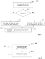
- FIG. 10 shows a flowchart of one embodiment of a method 200 of the invention.
- the individual steps of the method 200 are designated here by the reference symbols St1, St2, St3, etc.
- a basic selection can be made with the aid of a graphical user interface 80.
- the pipette type DiTi1 was selected here as part of a basic selection in both cases, as indicated in field 83.
- a selection can be made as to whether an aspiration process or a dispensing process should be defined.
- the selection of an aspirating submenu 85 or a dispensing submenu 86 is made possible on the hierarchical level H2.
- step St3 either the parameters of the aspirating process or the dispensing process can be defined.
- step St3 the associated parameters can be defined by the user or loaded from a memory. Step St3 is optional.
- step St4 at least one formula can be defined.
- the formula may be defined by the user or loaded from a memory.
- a corresponding formula field 88 is provided to define a formula or to edit an existing formula.
- step St5 the final parameters to be used in the implementation or execution of the process steps are calculated.
- a minimum check and a maximum check may be performed.
- a corresponding minimum field 91 and a maximum field 92 are provided.
- Step St6 is optional.
- step St7 the determined final parameters can be inserted into the grid of a liquid class.
- Step St7 is optional and is preferably used when the underlying handling system 100 is designed for processing fluid classes. In these cases, the inventive method can be placed on an existing handling system 100. The method of the invention is backward compatible if it includes step St7.
- step St8 the substeps of the aspirating process or the dispensing process are performed in a handling system 100.
- Steps St4, St5 and St6 are the dynamic part. That is, there may be mutual dependencies between these steps St4, St5, and St6.
- changes may occur that the handling system 100 and / or a computer 60 automatically makes.
- Fig. 8 shows a flowchart of an embodiment of another method 201 of the invention.
- the individual steps of the method 201 are designated here by the reference symbols St1, St2, St3, etc. Steps St1 and St2 are the same as or similar to Fig. 7 ,
- step St9 (similar to step St3), either the parameters and / or formulas of an aspirating process or a dispensing process can be defined.
- the parameters or formulas may be defined by the user or loaded from a memory. At least one formula is specified in step St9.
- step St10 (similar to step St8), the substeps of the aspirating process or the dispensing process are executed in the handling system 100.
- step St10 there is a kind of dynamic adaptation during the execution of the substeps, as in Fig. 8 indicated by the style step, logically connected to step St10 is, or which is in step with the step St10 interacts. Dynamic adaptation takes place during runtime.
- a method 201 Fig. 8 the final parameters are stored in a main memory just before the execution of a substep. Until the moment of dropping, the parameters can still be adjusted.
- a method and handling system 100 implementing this method can respond to changing conditions. If, for example, in a container 6 (see Fig. 1 ) is no longer sufficient volume of a liquid, the pipetting volume, which is used in a subsequent sub-step can be reduced (the reduction is done according to fixed rules and it is to be noted that there are sub-steps in which the adaptation of the Pipetting volume is not allowed, as it would lead to errors). Reducing the volume can in turn affect other parameters that are volume dependent. Such adjustments can be done almost in real time or almost in real time.
- FIG. 12 shows a flowchart of one embodiment of another method 202 of the invention.
- Fig. 9 indicates that the microscript-based procedure is performed after the parameters and / or formulas of pipetting have been defined.
- the microscript-based method can apply the parameters and formulas in step St13. For example, in step 026, if one defines the aspiration of air to later create an air plug (LAG) in a pipette 5 (as in FIG Fig. 6
- LAG air plug
- the parameters previously defined in step St 12 may be used.
- the corresponding parameters are displayed on the graphical user interface 80.
- a previous air plug LAG
- this parameter value in field 96 of FIG Fig. 6 are displayed. In Fig. 6 If so, this is exemplified in box 96 of step 026.
- Defining the substeps using the microscript-based method may result in changes that may affect other parameters or substeps.
- all embodiments are implemented such that there is some kind of computational feedback 204, as in FIG Fig. 9 indicated schematically.
- the feedback 204 is optional.
- FIG. 12 shows a flowchart of one embodiment of another method 202 of the invention.
- Fig. 10 indicates that the definition of the parameters and / or formulas of the pipetting is carried out in terms of time according to the microscript-based method. After the microscript-based method has been applied in a step St14, the parameters and formulas can be preset or adjusted in step St15. Feedback 204 is not required here.
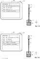
- FIGS. 11A to 11F For example, exemplary steps of a process performed in a handling system 100 of the invention are illustrated.
- the graphic surface 80 of a screen 81 is shown by way of example.
- a pipette 5 and a container 7, which is filled with a liquid F1 can be seen in schematic representation.
- the graphical user interface 80 may display in all embodiments a representation that illustrates, step by step, the progress of the process.
- the graphical user interface 80 may in all embodiments show a micro-script window 93 similar in structure to the micro-script window 93 in FIG Fig. 6 ,
- the step-by-step representation of the progress of the process can also take other forms in all embodiments.
- Fig. 11A shows the graphical interface 80 during a first aspiration step.
- the pipette 5 is located above the container 7.
- the musculoskeletal device 50 moves the pipette 5 relative to the container 7 to a position designated Z-start. From Z start, the pipette 5 is moved much slower down than during purely robotic movements in X, Y and Z.
- Fig. 11B shows the graphical interface 80 during a second aspiration step. In this step, air was aspirated from the pipette 5. In Fig. 11B one recognizes a small air plug 8 consisting of STAG and LAG at the lower end of the pipette 5.
- Fig. 11C shows the graphical interface 80 during a third aspiration step.
- a corresponding LLD circuit symbolized by the capacitor K
- LLD stands for liquid-level-detection, which means detection of a fluid level. The pipette 5 is then moved slowly from Z-start towards the liquid surface.
- Fig. 11D shows the graphical interface 80 during a fourth aspiration step.
- liquid Fl is aspirated from the container 7 with the pipette.
- the pipette 5 is moved downwardly by the musculoskeletal system 50 during aspiration, so as to follow the decreasing liquid level in the container 7.
- Aspiration is done with capacitive LLD monitoring. That is, if the pipette 5 would follow too slowly the liquid level falling during aspiration, the LLD circuit would be alarmed.
- Fig. 11E shows the graphical interface 80 during a fifth aspiration step.
- an LLD-monitored retraction of the pipette 5 from the container 7 takes place.
- a signal which is observed by the LLD circuit symbolized by the capacitor K) is indicated as soon as the pipette 5 has emerged from the liquid F1.
- the level of the liquid level after aspiration is subjected to a plausibility test on the basis of the aspirated volume and the vessel geometry.
- Fig. 11F shows the graphical interface 80 during a sixth aspiration step.
- the pipette 5 sucks air again.
- Fig. 11F one recognizes another small air plug 9, which is located at the lower end of the pipette 5.
- the liquid Fl is now in the pipette 5 of a preceding air plug 8 (LAG) and surrounded by a trailing air plug 9 (TAG).
- LAG preceding air plug 8
- TAG trailing air plug 9
- the pipette 5 can be moved to another position. Starting from this other position, then e.g. follow the substeps of a dispensing process. Again, the graphical interface 80 can display the individual sub-steps.
- the course of a pipetting process is rigidly predetermined.
- the pipette is moved in such a handling system to the height Z-Start.
- the STAG English: system trailing airgap
- the LAG English: leading airgap
- the pipette is then slowly moved downwards, with the LLD monitoring enabled, in the direction of the liquid surface until the liquid level is detected by the LLD circuit.
- the pipette is also immersed a little deeper into the liquid. Then the liquid is aspirated as the sum of excess volume (English: Excess), sample volume (Vol.) And conditioning volume (English: Cond.) With a predetermined speed in the liquid class.
- a handling system 100 can be used to change the order of individual steps, to define and insert further steps. For example, if it is a matter of aspirating a liquid that sits beneath another layer of liquid, then using a suitable microscript you can activate the LLD twice to find the phase boundary of the liquid you are looking for. There, the aspiration can then be made.
- a first liquid eg a buffer solution
- a second liquid eg the actual sample
Landscapes
- Engineering & Computer Science (AREA)
- Physics & Mathematics (AREA)
- General Physics & Mathematics (AREA)
- Chemical & Material Sciences (AREA)
- Biochemistry (AREA)
- Automation & Control Theory (AREA)
- Health & Medical Sciences (AREA)
- Life Sciences & Earth Sciences (AREA)
- Human Computer Interaction (AREA)
- Analytical Chemistry (AREA)
- Pathology (AREA)
- General Health & Medical Sciences (AREA)
- Immunology (AREA)
- Manufacturing & Machinery (AREA)
- General Engineering & Computer Science (AREA)
- Theoretical Computer Science (AREA)
- Sampling And Sample Adjustment (AREA)
- Automatic Analysis And Handling Materials Therefor (AREA)
Claims (15)
- Procédé destiné à définir un processus automatisé qui doit être réalisé dans un système de manipulation de liquide (100), le système de manipulation de liquide (100) comprenant :- un élément de sortie (5) pour aspirer et/ou distribuer un volume de liquide (x),- un appareil de déplacement à commande numérique (50) pour effectuer des déplacements (P1, P2, P3) en lien avec l'aspiration et/ou la distribution,- une commande (S) pour commander le processus,- une interface utilisateur graphique (80) pour afficher et/ou définir les paramètres pour effectuer le processus, et- un ensemble de paramètres, avec lequel la commande (S) commande le processus qui doit être réalisé dans le système de manipulation de liquide (100), des paramètres de cet ensemble de paramètres étant appliqués lorsqu'on effectue une ou plusieurs étapes du processus et étant des paramètres devant être définis directement par l'utilisateur au moyen de l'interface utilisateur graphique (80),caractérisé en ce qu'il est fourni dans l'interface utilisateur graphique (80) au moins une formule avec laquelle est amené dans une dépendance fonctionnelle au moins un premier paramètre (f(x)) devant être défini directement par l'utilisateur avec un deuxième paramètre (x) devant être défini directement par l'utilisateur, de sorte que le premier paramètre (f(x)), au lieu d'être défini par l'utilisateur, est adapté automatiquement par le système lorsque le deuxième paramètre (x) est modifié.
- Procédé selon la revendication 1, caractérisé en ce que l'interface utilisateur (80) permet à l'utilisateur, dans une première étape, de sélectionner directement un ou plusieurs paramètres, de préférence de sélectionner l'élément de sortie (5).
- Procédé selon la revendication 1 ou 2, caractérisé en ce que, dans une étape du procédé, il est fourni dans la zone de l'interface utilisateur (80) un champ de formule (88) de sorte que- l'utilisateur peut saisir la formule dans ce champ de formule (88), et/ou- l'utilisateur peut sélectionner la formule à partir d'une liste de formules et peut la reprendre dans ce champ de formule (88), et/ou- l'utilisateur peut éditer la formule qui est définie par le système dans le champ de formule (88).
- Procédé selon la revendication 3, caractérisé en ce qu'il est permis à l'utilisateur, dans une étape du procédé, d'indiquer dans le champ de formule (88) et/ou dans la formule une valeur minimum (Pmin) et une valeur maximum (Pmax).
- Procédé selon la revendication 3, caractérisé en ce qu'il est permis à l'utilisateur, dans une étape du procédé, de spécifier une fonction sigmoïde (SF).
- Procédé selon la revendication 5, caractérisé en ce qu'il est permis à l'utilisateur, dans une étape du procédé, d'indiquer pour la fonction sigmoïde (SF) au moins une constante (a, b, c, d) pour définir les propriétés de la fonction sigmoïde (SF).
- Procédé selon la revendication 1 ou 3, caractérisé en ce qu'il est permis à l'utilisateur, dans une étape du procédé, de mettre les étapes dans l'ordre chronologique les unes par rapport aux autres.
- Procédé selon l'une des revendications précédentes, caractérisé en ce que, dans une étape parallèle ou consécutive dans le temps, il est procédé à un ajustement mathématique entre deux étapes, dans le cas où ces deux étapes sont interdépendantes.
- Procédé selon l'une des revendications 2 à 7, caractérisé en ce qu'on utilise la formule pour procéder à l'ajustement mathématique entre deux étapes et/ou le premier paramètre (f(x)).
- Procédé selon l'une des revendications précédentes, caractérisé en ce qu'il est réalisé dans une étape consécutive dans le temps une simulation mathématique.
- Procédé selon l'une des revendications 1 à 9, caractérisé en ce qu'il est calculé, dans une étape consécutive dans le temps (St5), les paramètres définitifs.
- Procédé selon la revendication 1 pour réaliser un processus de pipetage dans le système de manipulation de liquide (100), caractérisé en ce que :- l'interface utilisateur graphique (80) est utilisée pour permettre à l'utilisateur de mettre les étapes du processus de pipetage dans un ordre chronologique, et- l'interface utilisateur graphique (80) et la formule sont utilisées pour permettre à l'utilisateur de définir une dépendance d'une première étape par rapport à une deuxième étape, de sorte que la première étape change après que la deuxième étape a été modifiée.
- Procédé selon la revendication 12, caractérisé en ce qu'il est utilisé comme formule une fonction sigmoïde (SF).
- Procédé selon la revendication 13, caractérisé en ce que, dans une étape du procédé, il peut être indiqué au niveau de la fonction sigmoïde (SF) au moins une constante (a, b, c, d) pour définir les propriétés de la fonction sigmoïde (SF).
- Procédé selon l'une des revendications précédentes, caractérisé en ce que l'ensemble de paramètres est fourni par une classe de liquide pouvant être sélectionnée par l'utilisateur, avec laquelle on peut définir un processus de pipetage pour des liquides spécifiques.
Priority Applications (2)
| Application Number | Priority Date | Filing Date | Title |
|---|---|---|---|
| EP14168144.5A EP2945033B1 (fr) | 2014-05-13 | 2014-05-13 | Procédé destiné à définir un processus dans un système de manipulation de liquide |
| US14/710,206 US9904295B2 (en) | 2014-05-13 | 2015-05-12 | Method for defining a process in a liquid handling system and a method for carrying out a pipetting process |
Applications Claiming Priority (1)
| Application Number | Priority Date | Filing Date | Title |
|---|---|---|---|
| EP14168144.5A EP2945033B1 (fr) | 2014-05-13 | 2014-05-13 | Procédé destiné à définir un processus dans un système de manipulation de liquide |
Publications (2)
| Publication Number | Publication Date |
|---|---|
| EP2945033A1 EP2945033A1 (fr) | 2015-11-18 |
| EP2945033B1 true EP2945033B1 (fr) | 2018-10-10 |
Family
ID=50828690
Family Applications (1)
| Application Number | Title | Priority Date | Filing Date |
|---|---|---|---|
| EP14168144.5A Active EP2945033B1 (fr) | 2014-05-13 | 2014-05-13 | Procédé destiné à définir un processus dans un système de manipulation de liquide |
Country Status (2)
| Country | Link |
|---|---|
| US (1) | US9904295B2 (fr) |
| EP (1) | EP2945033B1 (fr) |
Families Citing this family (4)
| Publication number | Priority date | Publication date | Assignee | Title |
|---|---|---|---|---|
| JP6800223B2 (ja) * | 2016-10-28 | 2020-12-16 | ベックマン コールター, インコーポレイテッド | 物質調製評価システム |
| CN110095623B (zh) * | 2019-04-18 | 2023-03-28 | 迈克医疗电子有限公司 | 一种速度控制的方法、装置、设备和介质 |
| CN115344174A (zh) * | 2022-08-11 | 2022-11-15 | 杭州术也科技有限公司 | 一种微孔板加样引导方法及系统 |
| USD1079747S1 (en) * | 2023-04-28 | 2025-06-17 | Google Llc | Display screen or portion thereof with icon |
Family Cites Families (8)
| Publication number | Priority date | Publication date | Assignee | Title |
|---|---|---|---|---|
| CH669851A5 (fr) | 1986-03-06 | 1989-04-14 | Tecan Ag | |
| US4967606A (en) * | 1988-04-29 | 1990-11-06 | Caveo Scientific Instruments, Inc. | Method and apparatus for pipetting liquids |
| WO1991006050A1 (fr) | 1989-10-17 | 1991-05-02 | Applied Biosystems, Inc. | Interface robotique |
| EP1191312A3 (fr) * | 2000-09-21 | 2004-12-22 | Tecan Trading AG | Système et méthode d'optimisation des paramètres d'instruments de manipulation de fluides |
| US6982063B2 (en) * | 2001-05-25 | 2006-01-03 | Matrix Technologies Corp | Automated pipetting system |
| JP3985665B2 (ja) * | 2002-11-18 | 2007-10-03 | 日立工機株式会社 | 自動分注装置 |
| US8225654B2 (en) | 2009-07-01 | 2012-07-24 | Tecan Trading Ag | Self-compensating capacitive liquid level detector |
| EP2713166B1 (fr) * | 2012-10-01 | 2019-05-22 | Eppendorf Ag | Automate de laboratoire et procédé de traitement automatique d'échantillons de laboratoire |
-
2014
- 2014-05-13 EP EP14168144.5A patent/EP2945033B1/fr active Active
-
2015
- 2015-05-12 US US14/710,206 patent/US9904295B2/en active Active
Non-Patent Citations (1)
| Title |
|---|
| None * |
Also Published As
| Publication number | Publication date |
|---|---|
| US20150331428A1 (en) | 2015-11-19 |
| US9904295B2 (en) | 2018-02-27 |
| EP2945033A1 (fr) | 2015-11-18 |
Similar Documents
| Publication | Publication Date | Title |
|---|---|---|
| DE69608705T2 (de) | Automatisches pipettieren von kleinen volumen | |
| DE69205613T2 (de) | Flüssigkeitsausgabe mit Behälterbodendetektion. | |
| EP2945033B1 (fr) | Procédé destiné à définir un processus dans un système de manipulation de liquide | |
| DE69220499T2 (de) | Methode zum ansaugen einer flüssigkeit | |
| EP2713166B1 (fr) | Automate de laboratoire et procédé de traitement automatique d'échantillons de laboratoire | |
| WO2018015419A1 (fr) | Pointe de pipette pour dispositif de pipetage automatique et procédé pour la réaliser | |
| EP3452835A1 (fr) | Pointe de pipette pour dispositif de pipetage automatique et procédé pour la réaliser | |
| DE3042915A1 (de) | Verfahren und vorrichtung zur automatischen analyse von fluidproben | |
| DE112010005239T5 (de) | Flüssigkeitsprobenanalysevorrichtung und Flüssigkeitsprobeneinführvorrichtung | |
| DE202006010293U1 (de) | Pipettiergerät mit Computerprogrammprodukt zum Akzeptieren oder Verwerfen von pipettierten Flüssigkeitsproben | |
| DE112011104019T5 (de) | Flüssigkeitschromatograph, Probeneingabevorrichtung für Flüssigkeitschromatographen und Verfahren zum Reinigen einer Probeeingabevorrichtung für Flüssigkeitschromatographen | |
| DE2640491A1 (de) | Automatischer pipettierapparat | |
| EP2633914B1 (fr) | Dispositif de pipetage et son procédé de fabrication | |
| DE69827952T2 (de) | Mikrovolumenfluessigkeitshandhabungssystem | |
| CH712764A2 (de) | Pipettenspitze aufweisend eine Volumenmesselektrode sowie Verfahren zu deren Herstellung und Pipettiervorrichtung. | |
| DE102020205073A1 (de) | Dosiereinrichtung und Verfahren zum Dosieren einer Flüssigkeit | |
| EP1355208A1 (fr) | Système d'automatisation de processus techniques | |
| DE102017216713A1 (de) | Verfahren und Dosiervorrichtung zur dosierten Fluidausgabe | |
| DE102012103573A1 (de) | Volumenmessung eines flüssigen Mediums, insbesondere eines Lösungsmittels in Flaschen in der HPLC | |
| WO2013053529A1 (fr) | Système de commande et procédé permettant de représenter une surface de commande | |
| DE112014004154T5 (de) | Automatische Analysevorrichtung | |
| EP2156890B1 (fr) | Agencement et procédé de production, de manipulation et d'analyse de compartiments | |
| DE4416406C2 (de) | Verfahren zum Ausgeben einer Flüssigkeitsprobe | |
| EP2006020B1 (fr) | Agencement de traitement d'échantillons pour un dispositif de dosage de liquides | |
| EP2440940B1 (fr) | Dispositif et procédé de formation et/ou d'agencement de successions d'un ou plusieurs échantillons de fluide dans un fluide porteur |
Legal Events
| Date | Code | Title | Description |
|---|---|---|---|
| PUAI | Public reference made under article 153(3) epc to a published international application that has entered the european phase |
Free format text: ORIGINAL CODE: 0009012 |
|
| AK | Designated contracting states |
Kind code of ref document: A1 Designated state(s): AL AT BE BG CH CY CZ DE DK EE ES FI FR GB GR HR HU IE IS IT LI LT LU LV MC MK MT NL NO PL PT RO RS SE SI SK SM TR |
|
| AX | Request for extension of the european patent |
Extension state: BA ME |
|
| 17P | Request for examination filed |
Effective date: 20160513 |
|
| RBV | Designated contracting states (corrected) |
Designated state(s): AL AT BE BG CH CY CZ DE DK EE ES FI FR GB GR HR HU IE IS IT LI LT LU LV MC MK MT NL NO PL PT RO RS SE SI SK SM TR |
|
| 17Q | First examination report despatched |
Effective date: 20160609 |
|
| STAA | Information on the status of an ep patent application or granted ep patent |
Free format text: STATUS: EXAMINATION IS IN PROGRESS |
|
| GRAP | Despatch of communication of intention to grant a patent |
Free format text: ORIGINAL CODE: EPIDOSNIGR1 |
|
| STAA | Information on the status of an ep patent application or granted ep patent |
Free format text: STATUS: GRANT OF PATENT IS INTENDED |
|
| RIC1 | Information provided on ipc code assigned before grant |
Ipc: G01N 35/00 20060101ALN20180223BHEP Ipc: B01L 3/02 20060101ALN20180223BHEP Ipc: G05B 19/409 20060101AFI20180223BHEP |
|
| INTG | Intention to grant announced |
Effective date: 20180314 |
|
| GRAJ | Information related to disapproval of communication of intention to grant by the applicant or resumption of examination proceedings by the epo deleted |
Free format text: ORIGINAL CODE: EPIDOSDIGR1 |
|
| STAA | Information on the status of an ep patent application or granted ep patent |
Free format text: STATUS: EXAMINATION IS IN PROGRESS |
|
| GRAP | Despatch of communication of intention to grant a patent |
Free format text: ORIGINAL CODE: EPIDOSNIGR1 |
|
| STAA | Information on the status of an ep patent application or granted ep patent |
Free format text: STATUS: GRANT OF PATENT IS INTENDED |
|
| INTC | Intention to grant announced (deleted) | ||
| RIC1 | Information provided on ipc code assigned before grant |
Ipc: G01N 35/00 20060101ALN20180628BHEP Ipc: B01L 3/02 20060101ALN20180628BHEP Ipc: G05B 19/409 20060101AFI20180628BHEP |
|
| INTG | Intention to grant announced |
Effective date: 20180713 |
|
| GRAS | Grant fee paid |
Free format text: ORIGINAL CODE: EPIDOSNIGR3 |
|
| GRAA | (expected) grant |
Free format text: ORIGINAL CODE: 0009210 |
|
| STAA | Information on the status of an ep patent application or granted ep patent |
Free format text: STATUS: THE PATENT HAS BEEN GRANTED |
|
| AK | Designated contracting states |
Kind code of ref document: B1 Designated state(s): AL AT BE BG CH CY CZ DE DK EE ES FI FR GB GR HR HU IE IS IT LI LT LU LV MC MK MT NL NO PL PT RO RS SE SI SK SM TR |
|
| REG | Reference to a national code |
Ref country code: GB Ref legal event code: FG4D Free format text: NOT ENGLISH |
|
| REG | Reference to a national code |
Ref country code: CH Ref legal event code: EP Ref country code: AT Ref legal event code: REF Ref document number: 1051974 Country of ref document: AT Kind code of ref document: T Effective date: 20181015 |
|
| REG | Reference to a national code |
Ref country code: CH Ref legal event code: NV Representative=s name: OK PAT AG PATENTE MARKEN LIZENZEN, CH Ref country code: IE Ref legal event code: FG4D Free format text: LANGUAGE OF EP DOCUMENT: GERMAN Ref country code: DE Ref legal event code: R096 Ref document number: 502014009676 Country of ref document: DE |
|
| REG | Reference to a national code |
Ref country code: NL Ref legal event code: MP Effective date: 20181010 |
|
| REG | Reference to a national code |
Ref country code: LT Ref legal event code: MG4D |
|
| PG25 | Lapsed in a contracting state [announced via postgrant information from national office to epo] |
Ref country code: NL Free format text: LAPSE BECAUSE OF FAILURE TO SUBMIT A TRANSLATION OF THE DESCRIPTION OR TO PAY THE FEE WITHIN THE PRESCRIBED TIME-LIMIT Effective date: 20181010 |
|
| PG25 | Lapsed in a contracting state [announced via postgrant information from national office to epo] |
Ref country code: NO Free format text: LAPSE BECAUSE OF FAILURE TO SUBMIT A TRANSLATION OF THE DESCRIPTION OR TO PAY THE FEE WITHIN THE PRESCRIBED TIME-LIMIT Effective date: 20190110 Ref country code: BG Free format text: LAPSE BECAUSE OF FAILURE TO SUBMIT A TRANSLATION OF THE DESCRIPTION OR TO PAY THE FEE WITHIN THE PRESCRIBED TIME-LIMIT Effective date: 20190110 Ref country code: PL Free format text: LAPSE BECAUSE OF FAILURE TO SUBMIT A TRANSLATION OF THE DESCRIPTION OR TO PAY THE FEE WITHIN THE PRESCRIBED TIME-LIMIT Effective date: 20181010 Ref country code: HR Free format text: LAPSE BECAUSE OF FAILURE TO SUBMIT A TRANSLATION OF THE DESCRIPTION OR TO PAY THE FEE WITHIN THE PRESCRIBED TIME-LIMIT Effective date: 20181010 Ref country code: IS Free format text: LAPSE BECAUSE OF FAILURE TO SUBMIT A TRANSLATION OF THE DESCRIPTION OR TO PAY THE FEE WITHIN THE PRESCRIBED TIME-LIMIT Effective date: 20190210 Ref country code: ES Free format text: LAPSE BECAUSE OF FAILURE TO SUBMIT A TRANSLATION OF THE DESCRIPTION OR TO PAY THE FEE WITHIN THE PRESCRIBED TIME-LIMIT Effective date: 20181010 Ref country code: LT Free format text: LAPSE BECAUSE OF FAILURE TO SUBMIT A TRANSLATION OF THE DESCRIPTION OR TO PAY THE FEE WITHIN THE PRESCRIBED TIME-LIMIT Effective date: 20181010 Ref country code: LV Free format text: LAPSE BECAUSE OF FAILURE TO SUBMIT A TRANSLATION OF THE DESCRIPTION OR TO PAY THE FEE WITHIN THE PRESCRIBED TIME-LIMIT Effective date: 20181010 Ref country code: FI Free format text: LAPSE BECAUSE OF FAILURE TO SUBMIT A TRANSLATION OF THE DESCRIPTION OR TO PAY THE FEE WITHIN THE PRESCRIBED TIME-LIMIT Effective date: 20181010 |
|
| PG25 | Lapsed in a contracting state [announced via postgrant information from national office to epo] |
Ref country code: AL Free format text: LAPSE BECAUSE OF FAILURE TO SUBMIT A TRANSLATION OF THE DESCRIPTION OR TO PAY THE FEE WITHIN THE PRESCRIBED TIME-LIMIT Effective date: 20181010 Ref country code: RS Free format text: LAPSE BECAUSE OF FAILURE TO SUBMIT A TRANSLATION OF THE DESCRIPTION OR TO PAY THE FEE WITHIN THE PRESCRIBED TIME-LIMIT Effective date: 20181010 Ref country code: SE Free format text: LAPSE BECAUSE OF FAILURE TO SUBMIT A TRANSLATION OF THE DESCRIPTION OR TO PAY THE FEE WITHIN THE PRESCRIBED TIME-LIMIT Effective date: 20181010 Ref country code: GR Free format text: LAPSE BECAUSE OF FAILURE TO SUBMIT A TRANSLATION OF THE DESCRIPTION OR TO PAY THE FEE WITHIN THE PRESCRIBED TIME-LIMIT Effective date: 20190111 Ref country code: PT Free format text: LAPSE BECAUSE OF FAILURE TO SUBMIT A TRANSLATION OF THE DESCRIPTION OR TO PAY THE FEE WITHIN THE PRESCRIBED TIME-LIMIT Effective date: 20190210 |
|
| REG | Reference to a national code |
Ref country code: DE Ref legal event code: R097 Ref document number: 502014009676 Country of ref document: DE |
|
| PG25 | Lapsed in a contracting state [announced via postgrant information from national office to epo] |
Ref country code: IT Free format text: LAPSE BECAUSE OF FAILURE TO SUBMIT A TRANSLATION OF THE DESCRIPTION OR TO PAY THE FEE WITHIN THE PRESCRIBED TIME-LIMIT Effective date: 20181010 Ref country code: DK Free format text: LAPSE BECAUSE OF FAILURE TO SUBMIT A TRANSLATION OF THE DESCRIPTION OR TO PAY THE FEE WITHIN THE PRESCRIBED TIME-LIMIT Effective date: 20181010 Ref country code: CZ Free format text: LAPSE BECAUSE OF FAILURE TO SUBMIT A TRANSLATION OF THE DESCRIPTION OR TO PAY THE FEE WITHIN THE PRESCRIBED TIME-LIMIT Effective date: 20181010 |
|
| PLBE | No opposition filed within time limit |
Free format text: ORIGINAL CODE: 0009261 |
|
| STAA | Information on the status of an ep patent application or granted ep patent |
Free format text: STATUS: NO OPPOSITION FILED WITHIN TIME LIMIT |
|
| PG25 | Lapsed in a contracting state [announced via postgrant information from national office to epo] |
Ref country code: RO Free format text: LAPSE BECAUSE OF FAILURE TO SUBMIT A TRANSLATION OF THE DESCRIPTION OR TO PAY THE FEE WITHIN THE PRESCRIBED TIME-LIMIT Effective date: 20181010 Ref country code: SK Free format text: LAPSE BECAUSE OF FAILURE TO SUBMIT A TRANSLATION OF THE DESCRIPTION OR TO PAY THE FEE WITHIN THE PRESCRIBED TIME-LIMIT Effective date: 20181010 Ref country code: EE Free format text: LAPSE BECAUSE OF FAILURE TO SUBMIT A TRANSLATION OF THE DESCRIPTION OR TO PAY THE FEE WITHIN THE PRESCRIBED TIME-LIMIT Effective date: 20181010 Ref country code: SM Free format text: LAPSE BECAUSE OF FAILURE TO SUBMIT A TRANSLATION OF THE DESCRIPTION OR TO PAY THE FEE WITHIN THE PRESCRIBED TIME-LIMIT Effective date: 20181010 |
|
| 26N | No opposition filed |
Effective date: 20190711 |
|
| PG25 | Lapsed in a contracting state [announced via postgrant information from national office to epo] |
Ref country code: SI Free format text: LAPSE BECAUSE OF FAILURE TO SUBMIT A TRANSLATION OF THE DESCRIPTION OR TO PAY THE FEE WITHIN THE PRESCRIBED TIME-LIMIT Effective date: 20181010 |
|
| PG25 | Lapsed in a contracting state [announced via postgrant information from national office to epo] |
Ref country code: MC Free format text: LAPSE BECAUSE OF FAILURE TO SUBMIT A TRANSLATION OF THE DESCRIPTION OR TO PAY THE FEE WITHIN THE PRESCRIBED TIME-LIMIT Effective date: 20181010 |
|
| REG | Reference to a national code |
Ref country code: BE Ref legal event code: MM Effective date: 20190531 |
|
| PG25 | Lapsed in a contracting state [announced via postgrant information from national office to epo] |
Ref country code: LU Free format text: LAPSE BECAUSE OF NON-PAYMENT OF DUE FEES Effective date: 20190513 |
|
| PG25 | Lapsed in a contracting state [announced via postgrant information from national office to epo] |
Ref country code: TR Free format text: LAPSE BECAUSE OF FAILURE TO SUBMIT A TRANSLATION OF THE DESCRIPTION OR TO PAY THE FEE WITHIN THE PRESCRIBED TIME-LIMIT Effective date: 20181010 |
|
| PG25 | Lapsed in a contracting state [announced via postgrant information from national office to epo] |
Ref country code: IE Free format text: LAPSE BECAUSE OF NON-PAYMENT OF DUE FEES Effective date: 20190513 |
|
| PG25 | Lapsed in a contracting state [announced via postgrant information from national office to epo] |
Ref country code: BE Free format text: LAPSE BECAUSE OF NON-PAYMENT OF DUE FEES Effective date: 20190531 |
|
| REG | Reference to a national code |
Ref country code: AT Ref legal event code: MM01 Ref document number: 1051974 Country of ref document: AT Kind code of ref document: T Effective date: 20190513 |
|
| REG | Reference to a national code |
Ref country code: CH Ref legal event code: PFUS Owner name: TECAN TRADING AG, CH Free format text: FORMER OWNER: TECAN TRADING AG, CH |
|
| PG25 | Lapsed in a contracting state [announced via postgrant information from national office to epo] |
Ref country code: AT Free format text: LAPSE BECAUSE OF NON-PAYMENT OF DUE FEES Effective date: 20190513 |
|
| PG25 | Lapsed in a contracting state [announced via postgrant information from national office to epo] |
Ref country code: CY Free format text: LAPSE BECAUSE OF FAILURE TO SUBMIT A TRANSLATION OF THE DESCRIPTION OR TO PAY THE FEE WITHIN THE PRESCRIBED TIME-LIMIT Effective date: 20181010 |
|
| PG25 | Lapsed in a contracting state [announced via postgrant information from national office to epo] |
Ref country code: HU Free format text: LAPSE BECAUSE OF FAILURE TO SUBMIT A TRANSLATION OF THE DESCRIPTION OR TO PAY THE FEE WITHIN THE PRESCRIBED TIME-LIMIT; INVALID AB INITIO Effective date: 20140513 Ref country code: MT Free format text: LAPSE BECAUSE OF FAILURE TO SUBMIT A TRANSLATION OF THE DESCRIPTION OR TO PAY THE FEE WITHIN THE PRESCRIBED TIME-LIMIT Effective date: 20181010 |
|
| PG25 | Lapsed in a contracting state [announced via postgrant information from national office to epo] |
Ref country code: MK Free format text: LAPSE BECAUSE OF FAILURE TO SUBMIT A TRANSLATION OF THE DESCRIPTION OR TO PAY THE FEE WITHIN THE PRESCRIBED TIME-LIMIT Effective date: 20181010 |
|
| REG | Reference to a national code |
Ref country code: FR Ref legal event code: PLFP Year of fee payment: 10 |
|
| P01 | Opt-out of the competence of the unified patent court (upc) registered |
Effective date: 20230522 |
|
| PGFP | Annual fee paid to national office [announced via postgrant information from national office to epo] |
Ref country code: DE Payment date: 20250402 Year of fee payment: 12 |
|
| PGFP | Annual fee paid to national office [announced via postgrant information from national office to epo] |
Ref country code: GB Payment date: 20250401 Year of fee payment: 12 |
|
| PGFP | Annual fee paid to national office [announced via postgrant information from national office to epo] |
Ref country code: FR Payment date: 20250401 Year of fee payment: 12 |
|
| PGFP | Annual fee paid to national office [announced via postgrant information from national office to epo] |
Ref country code: CH Payment date: 20250601 Year of fee payment: 12 |