EP2946760A1 - Lagerungselement - Google Patents
Lagerungselement Download PDFInfo
- Publication number
- EP2946760A1 EP2946760A1 EP15164956.3A EP15164956A EP2946760A1 EP 2946760 A1 EP2946760 A1 EP 2946760A1 EP 15164956 A EP15164956 A EP 15164956A EP 2946760 A1 EP2946760 A1 EP 2946760A1
- Authority
- EP
- European Patent Office
- Prior art keywords
- covering
- base
- bearing
- bearing element
- covering element
- Prior art date
- Legal status (The legal status is an assumption and is not a legal conclusion. Google has not performed a legal analysis and makes no representation as to the accuracy of the status listed.)
- Granted
Links
Images

Classifications
-
- A—HUMAN NECESSITIES
- A61—MEDICAL OR VETERINARY SCIENCE; HYGIENE
- A61G—TRANSPORT, PERSONAL CONVEYANCES, OR ACCOMMODATION SPECIALLY ADAPTED FOR PATIENTS OR DISABLED PERSONS; OPERATING TABLES OR CHAIRS; CHAIRS FOR DENTISTRY; FUNERAL DEVICES
- A61G13/00—Operating tables; Auxiliary appliances therefor
- A61G13/10—Parts, details or accessories
- A61G13/12—Rests specially adapted therefor; Arrangements of patient-supporting surfaces
Definitions
- the invention relates to a storage element according to the preamble of claim 1.
- first positioning shells are sawed from a foam block and then milled for finishing by means of CNC machining in the form.
- the surface of a shell is then sealed, for example by means of a polyurethane coating, to prevent ingress of bodily fluids or other contamination.
- a head shell for a CT system in which the head of a patient can be stored and fixed.
- it is at least one partially transparent shell, which on the one hand allows a position determination of the head by means of laser radiation and on the other hand allows a secure fixation of the head.
- at least one transparent window part is arranged on the head shell.
- the head shell can also be made completely transparent. With the laser, the head can be scanned and stored this targeted, or be aligned.
- Further head shells are from the DE 20 2011 104 541 U1 known. These are designed to allow the use of video glasses in variable storage positions.
- the bearing element has at the points special recesses, where the eyeglass temple runs along the head of a patient. Also different storage positions for back or side storage are taken into account.
- the object of the invention is to expand a storage element for medical technology of the known type to new approaches.
- the invention includes a bearing element consisting of a forming base having a surface formed of side surfaces, top and bottom and a coating element having an interior surface and an exterior surface.
- the coating element covers at least a part of the surface of the base member and is made of a thermoplastic material.
- the invention is based on the consideration that the forming element is used for reusable applications, whereas the coating element is designed as a disposable or as a cleanable reusable article.
- These positioning elements are used for the positioning of the head and limbs in X-rays, computed tomography, radiotherapy, radiological treatment and other medical examinations. Consequently, wherever a patient positioning and positioning of the head is needed.
- the field of application of the storage elements according to the invention is the medical field, in particular on couches or plates.
- a specially ergonomically adapted shape is made in each case.
- Deep drawing is suitable as a production technology associated with the thermo-forming process for numerous component geometries. Deep drawing is carried out in special thermoforming machines. For this purpose, a thermoplastic material is heated to forming temperature. The heated material is molded by vacuum into a thermoforming mold. The thermoforming mold is usually made of aluminum or steel. The cooling of the parts takes place in the tool. The hardened material can then be removed from the mold.
- a basic element for example, with a receiving device of a couch, be firmly connected.
- the coating element is positioned over it.
- a base member may be interchangeably positioned and retained within the associated receptacle.
- a particular advantage of the invention is that the risk of infection is reduced by a replaceable coating element.
- the hygiene requirements for cleaning and disinfecting the surface are guaranteed.
- the coating element is stackable in a small space during cleaning and thus designed to save space or anatomically shaped. This reduces the cleaning and disinfection effort.
- the base element and / or the covering element can be made of radiation-resistant material. Both have a solid structure, are storage stable and have a low radiation absorption.
- the cover element can either be disposed of or cleaned or disinfected and reused after use.
- the base element may consist of thermoplastic material.
- thermoplastic materials are extremely soft, preventing pressure points on the back of the head, the eyelids and cheekbones.
- the coating element of an organic sheet PE (polyethylene), synthetic leather, PC (polycarbonate) or carbon exist.
- PE polyethylene
- PC polycarbonate
- the coating elements can get a smooth, closed-cell surface that is very easy to clean and disinfect.
- the use of these materials is also economical due to their longevity.
- the base element of ABS (acrylonitrile-butadiene-styrene), PET (polyethylene terephthalate), TPU (thermoplastic Elastomer), carbon, PHB (polyhydroxybutyrate), PP (polypropylene) or PC (polycarbonate).
- ABS acrylonitrile-butadiene-styrene
- PET polyethylene terephthalate
- TPU thermoplastic Elastomer
- carbon PHB (polyhydroxybutyrate), PP (polypropylene) or PC (polycarbonate).
- PHB polyhydroxybutyrate
- PP polypropylene
- PC polycarbonate
- a holding element can be arranged on the base element.
- the storage elements can be fixed on a solid surface.
- the holding elements can be screwed, plugged or bayonet connections, which form, for example, a form or frictional connection with the base.
- With a holding element can also be performed by a height or lateral adjustment fine adjustment of the limbs for proper positioning.
- the coating element may at least partially consist of elastic material. This supports the easy positioning of the cover element on the base element. Such materials also often have a large coefficient of friction in order to prevent a force slippage relative to the base element.
- the inner surface of the coating element can simulate the contour of the surface of the base element.
- undercuts or concave surface areas of the base element are also lined so that the two parts are aligned adjacent to one another.
- the surface of the base member may have edges and overlap the coating element on this on the side surfaces.
- the coating element already sufficient a slight attack.
- an attack and covering are contemplated wherever a body part may come into contact with the surface of the bearing element.
- the overarching part of the covering element can be designed as a tensioning element.
- Clamping elements cause a particularly stable seat and can be wrinkle-free on the base element in a relatively thin design.
- the overarching part of the coating element may have a different material thickness than the remaining part of the coating element.
- a different material thickness is considered at the areas with greater force. The thinner areas can be made all the more elastic.
- At least the outer surface of the covering element may be made of a material which is impermeable to liquids.
- the primitive is effectively protected. This allows it to be used several times without intermediate cleaning.
- the base element and / or the covering element can be produced by means of a thermal deep-drawing process. In such forming a dimensional stability is given, so that a snug fit of the contact surfaces of both parts is guaranteed.
- At least the outer surface of the covering element can be made of a smooth and closed-cell material. Such materials are usually dense to liquid passage.
- the shape of the covering element for a bearing element can already have the surface contour of an associated base element. This results in a good handling when assembling the items and disassembly for a cleaning step.
- Fig. 1 schematically shows a view of a coating element 3.
- the inner surface 31 and the outer surface 32 of the coating element 3 in their entirety give an already preformed contour.
- the two mutually parallel side surfaces 33 are connected to each other via the top surface 34.
- the thermoplastic material is strong enough to provide the outer shape stable and storage resistant.
- the covering element 3 is made of radiation-resistant material. Trained as an independent item, a cover element 3 can be cleaned or disinfected several times for reuse.
- Fig. 2 schematically shows a view of a base element 2 as a headrest.
- the base member 2 is made of thermoplastic material and is usually particularly elastic to prevent pressure points on the contact surfaces with the body.
- the surface 21 of the base member 2 is ergonomically adapted to the head shape.
- the top 212 thus has a curved shape.
- the side surfaces 211 and the bottom 213 are flat surfaces. The transition of the upper side 212 to the side surfaces 211 is configured with a pronounced edge 22.
- On the bottom 213, a in the FIG. 2 not shown in detail retaining element can be arranged. Also recesses for receiving pins or otherwise suitable fasteners may be incorporated in the base element 2.
- Fig. 3 schematically shows a side view of the contour of a covering element 3 with a constant wall thickness.
- the side surfaces 33 and the top surface 34 of the coating element 3 are made of elastic and dimensionally stable material of the same thickness.
- Such coating elements 3 have a smooth surface, which is very easy to clean.
- Fig. 4 schematically shows a side view of the contour of a covering element 3 with varying wall thickness.
- the side surfaces 33 are formed with a smaller wall thickness.
- the overarching part of the covering element 3 has a different material thickness than the cover surface 34. The thinner areas can thereby be made all the more elastic.
- Fig. 5 schematically shows a view of a base member 2 with a precisely shaped coating element 3 prior to assembly to the entire storage element 1.
- the inner surface 31 of the coating element 3 forms the contour of the top 212 of the base member 2 after.
- concave surface regions of the base element 2 are also lined, thus bringing both parts into contact with each other.
- Fig. 6 schematically shows a view of a base member 2 with a precisely shaped coating element 3 when joining into a storage element 1. Both parts fit this form-fitting into each other.
- Fig. 7 schematically shows a view of an assembled storage element 1 as a head rest.
- the basic element 2 and the covering element 3 form a compact and stable unit for body storage.
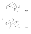
- Fig. 8 schematically shows a view of a coating element 3 with material recesses on a side surface 33, formed as a bow-like clamping element.
- a material saving can be considered without sacrificing stability at the locations that do not come into contact with a body part.
- this side surface 33 this is the case with a head mount.
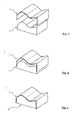
- Fig. 9 schematically shows a view of a cover member 3 with all sides overlapping side surfaces 33.
- the cover member engages over a plurality of edges on the side surfaces of a base member, not shown.
- a good fit and fit of the covering element 3 even a minor attack already sufficient. Also in this case, an attack and covering are contemplated wherever in use the head of the patient comes in contact with the surface of the bearing element.
Landscapes
- Health & Medical Sciences (AREA)
- Engineering & Computer Science (AREA)
- Biomedical Technology (AREA)
- Life Sciences & Earth Sciences (AREA)
- Animal Behavior & Ethology (AREA)
- General Health & Medical Sciences (AREA)
- Public Health (AREA)
- Veterinary Medicine (AREA)
- Orthopedics, Nursing, And Contraception (AREA)
- Accommodation For Nursing Or Treatment Tables (AREA)
Abstract
Description
- Die Erfindung betrifft ein Lagerungselement gemäß dem Oberbegriff des Anspruchs 1.
- Bei ärztlichen Untersuchungen oder Eingriffen ist es oft Voraussetzung, dass der Kopf des Patienten stabil und bequem gelagert wird, was mit Hilfe von Kissen oder Kopfschalen mit ausgeformten Höhlungen für die Aufnahme von Kopf und Hals erreicht werden kann. Naturgemäß sind für die verschiedenen Lagerungsarten jeweils gesonderte Lagerungselemente nötig, die sich in ihrer Form wesentlich voneinander unterscheiden können. Dies führt beispielsweise in einem Operationsbereich zu einem erheblichen Lagerplatz- und Reinigungsbedarf, da es durchaus vorkommen kann, dass ein Patient während einer Operation mehrfach umgelagert werden muss und so auch mehrere Lagerungselemente benötigt.
- Zum Stand der Technik gehören indes auch Vorrichtungen für Bauchlagerungen, die im weitesten Sinne als Modifikationen von Lagerungselementen für Rückenlagerungen aufgefasst werden können, da sie oft zusätzlich Aussparungen für Augen und Nase aufweisen. In manchen Anwendungen werden zuerst Positionierschalen aus einem Schaumstoffblock gesägt und danach zur Feinbearbeitung mittels CNC-Bearbeitung in Form gefräst. Die Oberfläche einer Schale wird dann versiegelt, beispielsweise mittels einer Beschichtung mit Polyurethan, um ein Eindringen von Körperflüssigkeiten oder eine anderweitige Verschmutzung zu vermeiden.
- Aus der Druckschrift
DE 10 2012 214 755 A1 sind Halterungen mit einer Kopfschale für ein CT-System bekannt, in welcher der Kopf eines Patienten gelagert und fixiert werden kann. In diesem Falle handelt es sich um eine zumindest teilweise durchsichtige Schale, welche einerseits eine Positionsbestimmung des Kopfes mittels Laserstrahlung zulässt und andererseits eine sichere Fixierung des Kopfes ermöglicht. Hierzu wird vorgeschlagen, dass mindestens ein durchsichtiges Fensterteil an der Kopfschale angeordnet ist. Alternativ kann die Kopfschale auch vollständig durchsichtig ausgeführt sein. Mit dem Laser kann der Kopf abgetastet und dieser gezielt gelagert, beziehungsweise ausgerichtet werden. - Weitere Kopfschalen sind aus der
DE 20 2011 104 541 U1 bekannt. Diese sind so konzipiert, dass eine Nutzung einer Videobrille in variablen Lagerungspositionen möglich ist. Hierzu hat das Lagerungselement an den Stellen besondere Aussparungen, an denen der Brillenbügel am Kopf eines Patienten entlangläuft. Auch unterschiedliche Lagerungspositionen für Rücken- oder Seitenlagerung sind dabei berücksichtigt. - Eine stetig ansteigende Differenziertheit derartiger Anwendungen macht eine ständige Materialweiterentwicklung unverzichtbar. Eine wichtige Voraussetzung für den Erfolg derartiger Medizinprodukte in den jeweiligen Anwendungsfeldern bleibt die einfache Handhabbarkeit und die erforderliche Reinigbarkeit.
- Aufgabe der Erfindung ist es, ein Lagerungselement für die Medizintechnik der bekannten Art um neue Ansätze zu erweitern.
- Erfindungsgemäß wird diese Aufgabe mit den in Anspruch 1 genannten Merkmalen gelöst. Die weiteren rückbezogenen Ansprüche betreffen vorteilhafte Aus- und Weiterbildungen der Erfindung.
- Die Erfindung schließt ein Lagerungselement ein, bestehend aus einem formgebenden Grundelement mit einer Oberfläche, die aus Seitenflächen, Oberseite und Unterseite gebildet wird, und einem Überzugelement mit einer Innenoberfläche und einer Außenoberfläche. Das Überzugelement bedeckt zumindest einen Teil der Oberfläche des Grundelements und besteht aus einem thermoplastischen Material.
- Die Erfindung geht dabei von der Überlegung aus, dass das formgebende Grundelement für Mehrweganwendungen dient, wohingegen das Überzugelement als Einweg- oder als reinigbarer Mehrweggegenstand ausgeführt ist. Diese Lagerungselemente dienen zur Positionierung von Kopf und Gliedmaßen beim Röntgen, bei der Computertomographie, der Strahlentherapie, der radiologischen Behandlung sowie sonstigen ärztlichen Untersuchungen. Folglich überall dort, wo eine Patientenlagerung und Positionierung des Kopfes benötigt wird.
- Das Einsatzgebiet der erfindungsgemäßen Lagerungselemente ist der Medizinbereich, insbesondere auf Liegen oder Platten. Hierzu wird jeweils eine speziell ergonomisch angepasste Form angefertigt.
- Lagerungselemente für die Medizintechnik, insbesondere als Kopf- und Fußschalen für die Mehrfachanwendung sowie die zugehörigen Einwegprodukte, können im Tiefziehverfahren hergestellt werden. Im Bereich der Automatisierung eignet sich das Tiefziehen als eine dem Thermo-Umformverfahren zugeordnete Produktionstechnologie für zahlreiche Bauteilgeometrien. Das Tiefziehen wird in speziellen Thermoformmaschinen durchgeführt. Hierzu wird ein thermoplastisches Material auf Umformtemperatur erwärmt. Das erwärmte Material wird mittels Vakuum in eine Tiefziehform eingeformt. Die Tiefziehform wird meist aus Aluminium oder Stahl gefertigt. Die Abkühlung der Teile findet im Werkzeug statt. Das erhärtete Material kann anschließend aus der Form entnommen werden.
- Mittlerweile können auch im sogenannten "Twin-Sheet-Verfahren" serientaugliche und maßhaltige Produkte gefertigt werden, die dem Komfort des Patienten entgegenkommen. Insgesamt kann mit diesen Methoden der Produktionsaufwand wirtschaftlicher gestaltet werden. Mit diesem Verfahren kann ein Grundelement, beispielsweise mit einer Aufnahmevorrichtung einer Liege, fest verbunden werden. Darüber wird das Überzugelement positioniert. Alternativ kann ein Grundelement in der zugehörigen Aufnahme austauschbar positioniert und gehalten werden.
- Ein besonderer Vorteil der Erfindung ist, dass das Infektionsrisiko durch ein auswechselbares Überzugelement gesenkt wird. Die Hygieneanforderungen hinsichtlich Reinigung und Desinfektion der Oberfläche sind gewährleistet. Zudem ist das Überzugelement auf kleinem Raum während der Reinigung stapelbar und damit platzsparend ausgeführt bzw. anatomisch ausgeformt. Damit wird der Reinigungs- und Desinfektionsaufwand reduziert.
- In bevorzugter Ausgestaltung der Erfindung kann das Grundelement und/oder das Überzugelement aus strahlungsresistentem Material gefertigt sein. Beide besitzen eine feste Struktur, sind lagerungsbeständig und haben eine geringe Strahlenabsorption. Das Überzugelement kann nach der Benutzung entweder entsorgt oder gereinigt bzw. desinfiziert und wiederverwendet werden.
- In einer vorteilhaften Ausführungsform kann das Grundelement aus thermoplastischem Material bestehen. Manche thermoplastischen Materialien sind extrem weich und verhindern so Druckstellen, beispielsweise am Hinterkopf wie auch im Bereich der Augenlider und Wangenknochen.
- Vorteilhafterweise kann das Überzugelement aus einem Organoblech, PE (Polyethylen), Kunstleder, PC (Polycarbonat) oder Carbon bestehen. Hierdurch können die Überzugelemente eine glatte, geschlossenzellige Oberfläche bekommen, die sehr leicht zu reinigen und zu desinfizieren ist. Der Einsatz dieser Materialien ist auch aufgrund Ihrer Langlebigkeit entsprechend wirtschaftlich.
- In weiterer vorteilhafter Ausgestaltung kann das Grundelement aus ABS (Acrylnitril-Butadien-Styrol), PET (Polyethylenterephthalat), TPU (Thermoplastisches Elastomer), Carbon, PHB (Polyhydroxybutyrat), PP (Polypropylen) oder PC (Polycarbonat) bestehen. Bei der Ausgestaltung des Grundelements sind außer der Materialbeschaffenheit zur guten Fixierung der Gliedmaßen beispielsweise auch die Lage und Form der Ausgänge von Tuben fertigungstechnisch zu berücksichtigen.
- Bevorzugt kann am Grundelement ein Halteelement angeordnet sein. Mit diesem können die Lagerungselemente auf einer festen Unterlage fixiert werden. Die Halteelemente können Schraub-, Steck- oder Bajonettverbindungen sein, die beispielsweise mit der Unterlage einen Form- oder Reibschluss eingehen. Mit einem Halteelement kann auch durch eine Höhen- oder Seitenverstellung eine Feinjustierung der Gliedmaßen zur richtigen Positionierung durchgeführt werden.
- In bevorzugter Ausgestaltung der Erfindung kann das Überzugelement zumindest teilweise aus elastischem Material bestehen. Dieses unterstützt die einfache Positionierung des Überzugelements auf dem Grundelement. Derartige Materialien weisen auch oft einen großen Reibkoeffizienten auf, um bei Krafteinwirkung ein Verrutschen gegenüber dem Grundelement zu verhindern.
- Vorteilhafterweise kann die Innenoberfläche des Überzugelements die Kontur der Oberfläche des Grundelements nachbilden. Durch eine nachgebildete Kontur werden auch Hinterschneidungen oder konkave Oberflächenbereiche des Grundelements ausgekleidet und so beide Teile aneinanderliegend zur Deckung gebracht.
- In bevorzugter Ausgestaltung der Erfindung kann die Oberfläche des Grundelements Kanten aufweisen und das Überzugelement über diese auf die Seitenflächen übergreifen. Für einen guten und passgenauen Sitz des Überzugelements reicht bereits ein geringfügiger Übergriff aus. Außerdem sind ein Übergriff und ein Bedecken überall dort angedacht, wo ein Körperteil mit der Oberfläche des Lagerungselements in Berührung kommen kann.
- Vorteilhafterweise kann der übergreifende Teil des Überzugelements als Spannelement ausgebildet sein. Spannelemente bewirken einen besonders stabilen Sitz und lassen sich in einer relativ dünnen Ausführung faltenfrei auf dem Grundelement überstülpen.
- In bevorzugter Ausgestaltung der Erfindung kann der übergreifende Teil des Überzugelements eine andere Materialstärke aufweisen, als der übrige Teil des Überzugelements. Aus Stabilitätsgründen ist eine unterschiedliche Materialstärke an den Bereichen mit größerer Krafteinwirkung angedacht. Die dünneren Bereiche können dabei umso elastischer ausgebildet werden.
- Vorteilhafterweise kann zumindest die Außenoberfläche des Überzugelements aus einem Material gefertigt sein, das gegenüber Flüssigkeiten undurchlässig ist. Auf diese Weise wird das Grundelement wirksam geschützt. Dadurch kann dieses auch ohne Zwischenreinigung mehrmals verwendet werden.
- In einer bevorzugten Ausführungsform können das Grundelement und/oder das Überzugelement mittels eines thermischen Tiefziehverfahrens hergestellt sein. Bei derartigen Umformverfahren ist eine Maßhaltigkeit gegeben, sodass ein passgenauer Sitz der Kontaktflächen beider Teile gewährleistet wird.
- Vorteilhafterweise kann zumindest die Außenoberfläche des Überzugelements aus einem glatten und geschlossenzelligen Material gefertigt sein. Derartige Materialien sind üblicherweise gegenüber einem Flüssigkeitsdurchtritt dicht.
- Des Weiteren kann die Form des Überzugelements für ein Lagerungselement bereits die Oberflächenkontur eines zugehörigen Grundelements aufweisen. Hierdurch stellt sich eine gute Handhabbarkeit beim Zusammenfügen der Einzelteile und zum Auseinandernehmen für einen Reinigungsschritt ein.
- Weitere vorteilhafte Weiterbildungen und Ausgestaltungen der Erfindung ergeben sich aus den nachfolgend anhand der Zeichnungen prinzipmäßig beschriebenen Ausführungsbeispielen.
- Es zeigen:
- Fig. 1
- schematisch eine Ansicht eines Überzugelements;
- Fig. 2
- schematisch eine Ansicht eines Grundelements als Kopfauflage;
- Fig. 3
- schematisch eine Seitenansicht der Kontur eines Überzugelements mit gleichbleibender Wandstärke;
- Fig. 4
- schematisch eine Seitenansicht der Kontur eines Überzugelements mit variierender Wandstärke;
- Fig. 5
- schematisch eine Ansicht eines Grundelements mit einem passgenau geformten Überzugelement vor dem Zusammenfügen;
- Fig. 6
- schematisch eine Ansicht eines Grundelements mit einem passgenau geformten Überzugelement beim Ineinanderfügen;
- Fig. 7
- schematisch eine Ansicht eines zusammengefügten Lagerungselements als Kopfauflage;
- Fig. 8
- schematisch eine Ansicht eines Überzugelements mit Materialaussparungen an einer Seitenfläche; und
- Fig. 9
- schematisch eine Ansicht eines Überzugelements mit allseitig übergreifenden Seitenflächen.
-
Fig. 1 zeigt schematisch eine Ansicht eines Überzugelements 3. Die Innenoberfläche 31 und die Außenoberfläche 32 des Überzugelements 3 ergeben in ihrer Gesamtheit einen bereits vorgeformten Konturverlauf. Die zwei parallel zueinander stehenden Seitenflächen 33 sind über die Deckfläche 34 miteinander verbunden. Das thermoplastische Material ist ausreichend stark, um die äußere Gestalt stabil und lagerungsbeständig vorzugeben. Als ein Beitrag zur Langlebigkeit ist das Überzugelement 3 aus strahlungsresistentem Material gefertigt. Ausgebildet als selbständiges Einzelteil kann ein Überzugelement 3 zur erneuten Benutzung mehrmals gereinigt bzw. desinfiziert werden. -
Fig. 2 zeigt schematisch eine Ansicht eines Grundelements 2 als Kopfauflage. Das Grundelement 2 besteht aus thermoplastischem Material und ist im Regelfall besonders elastisch, um Druckstellen an den Kontaktflächen mit dem Körper zu verhindern. Die Oberfläche 21 des Grundelements 2 ist ergonomisch an die Kopfform angepasst. Die Oberseite 212 hat folglich eine geschwungene Form. Die Seitenflächen 211 und die Unterseite 213 sind ebene Flächen. Der Übergang der Oberseite 212 zu den Seitenflächen 211 ist mit einer ausgeprägten Kante 22 ausgestaltet. Auf der Unterseite 213 kann ein in derFigur 2 nicht näher dargestelltes Halteelement angeordnet sein. Auch Ausnehmungen zur Aufnahme von Zapfen oder anderweitig geeigneten Verbindungselementen können im Grundelement 2 eingebracht sein. -
Fig. 3 zeigt schematisch eine Seitenansicht der Kontur eines Überzugelements 3 mit gleichbleibender Wandstärke. Die Seitenflächen 33 und die Deckfläche 34 des Überzugelements 3 bestehen aus elastischem und dabei formstabilen Material gleicher Dicke. Derartige Überzugelemente 3 besitzen eine glatte Oberfläche, die sehr leicht zu reinigen ist. -
Fig. 4 zeigt schematisch eine Seitenansicht der Kontur eines Überzugelements 3 mit variierender Wandstärke. Bei dieser Ausführungsform sind die Seitenflächen 33 mit geringerer Wandstärke ausgebildet. So weist der übergreifende Teil des Überzugelements 3 eine andere Materialstärke auf als die Deckfläche 34. Die dünneren Bereiche können dadurch umso elastischer ausgebildet werden. -
Fig. 5 zeigt schematisch eine Ansicht eines Grundelements 2 mit einem passgenau geformten Überzugelement 3 vor dem Zusammenfügen zum gesamten Lagerungselement 1. Die Innenoberfläche 31 des Überzugelements 3 bildet die Kontur der Oberseite 212 des Grundelements 2 nach. Durch eine nachgebildete Kontur werden auch konkave Oberflächenbereiche des Grundelements 2 ausgekleidet und so beide Teile aneinander liegend zur Deckung gebracht. -
Fig. 6 zeigt schematisch eine Ansicht eines Grundelements 2 mit einem passgenau geformten Überzugelement 3 beim Ineinanderfügen zu einem Lagerungselement 1. Beide Teile passen hierbei formschlüssig ineinander. -
Fig. 7 zeigt schematisch eine Ansicht eines zusammengefügten Lagerungselements 1 als Kopfauflage. Das Grundelement 2 und das Überzugelement 3 bilden eine kompakte und stabile Einheit zur Körperlagerung. -
Fig. 8 zeigt schematisch eine Ansicht eines Überzugelements 3 mit Materialaussparungen an einer Seitenfläche 33, ausgebildet als bügelartiges Spannelement. Eine derartige Materialersparnis kann ohne Stabilitätseinbußen an den Stellen in Betracht gezogen werden, die nicht mit einem Körperteil in Berührung kommen. An dieser Seitenfläche 33 ist dies bei einer Kopflagerung der Fall. -
Fig. 9 zeigt schematisch eine Ansicht eines Überzugelements 3 mit allseitig übergreifenden Seitenflächen 33. Das Überzugelement greift über mehrere Kanten auf die Seitenflächen eines nicht dargestellten Grundelements über. Für einen guten und passgenauen Sitz des Überzugelements 3 reicht auch ein geringfügigerer Übergriff bereits aus. Auch in diesem Fall sind ein Übergriff und ein Bedecken überall dort angedacht, wo im Einsatz der Kopf des Patienten mit der Oberfläche des Lagerungselements in Berührung kommt. -
- 1
- Lagerungselement
- 2
- Grundelement
- 21
- Oberfläche des Grundelements
- 211
- Seitenflächen des Grundelements
- 212
- Oberseite
- 213
- Unterseite
- 22
- Kante
- 3
- Überzugelement
- 31
- Innenoberfläche des Überzugelements
- 32
- Außenoberfläche des Überzugelements
- 33
- Seitenfläche, Spannelement
- 34
- Deckfläche
Claims (15)
- Lagerungselement (1), bestehend aus einem formgebenden Grundelement (2) mit einer Oberfläche (21), die aus Seitenflächen (211), Oberseite (212) und Unterseite (213) gebildet wird, und einem Überzugelement (3) mit einer Innenoberfläche (31) und einer Außenoberfläche (32),
dadurch gekennzeichnet, dass das Überzugelement (3) zumindest einen Teil der Oberfläche (21) des Grundelements (2) bedeckt und aus einem thermoplastischen Material besteht. - Lagerungselement (1) nach Anspruch 1,
dadurch gekennzeichnet, dass das Grundelement (2) und/oder das Überzugelement (3) aus strahlungsresistentem Material gefertigt ist. - Lagerungselement (1), nach Anspruch 1 oder 2,
dadurch gekennzeichnet, dass das Grundelement (2) aus thermoplastischem Material besteht. - Lagerungselement (1) nach einem der Ansprüche 1 bis 3,
dadurch gekennzeichnet, dass das Überzugelement (3) aus einem Organoblech, PE, Kunstleder, PC oder Carbon besteht. - Lagerungselement (1), nach einem der Ansprüche 1 bis 4,
dadurch gekennzeichnet, dass das Grundelement (2) aus ABS, PET, TPU, Carbon, PHB, PP oder PC besteht. - Lagerungselement (1) nach einem der Ansprüche 1 bis 5,
dadurch gekennzeichnet, dass am Grundelement (2) ein Halteelement angeordnet ist. - Lagerungselement (1) nach einem der Ansprüche 1 bis 6,
dadurch gekennzeichnet, dass das Überzugelement (3) zumindest teilweise aus elastischem Material besteht. - Lagerungselement (11) nach einem der Ansprüche 1 bis 7,
dadurch gekennzeichnet, dass die Innenoberfläche (31) des Überzugelements (3) die Kontur der Oberfläche (21) des Grundelements (2) nachbildet. - Lagerungselement (1) nach einem der Ansprüche 1 bis 8,
dadurch gekennzeichnet, dass die Oberfläche (21) des Grundelements (2) Kanten (22) aufweist und das Überzugelement (3) über eine Kante (22) oder mehrere Kanten (22) auf die Seitenflächen (211) übergreift. - Lagerungselement (1) nach einem der Ansprüche 1 bis 9,
dadurch gekennzeichnet, dass der übergreifende Teil des Überzugelements (3) als Spannelement (33) ausgebildet ist. - Lagerungselement (1) nach einem der Ansprüche 1 bis 10,
dadurch gekennzeichnet, dass der übergreifende Teil des Überzugelements (3) eine andere Materialstärke aufweist als der übrige Teil des Überzugelements (3). - Lagerungselement (1) nach einem der Ansprüche 1 bis 11,
dadurch gekennzeichnet, dass zumindest die Außenoberfläche (32) des Überzugelements (3) aus einem Material gefertigt ist, das gegenüber Flüssigkeiten undurchlässig ist. - Lagerungselement (1) nach einem der Ansprüche 1 bis 12,
dadurch gekennzeichnet, dass das Grundelement (2) und/oder das Überzugelement (3) mittels eines thermischen Tiefziehverfahrens hergestellt ist. - Lagerungselement (1) nach einem der Ansprüche 1 bis 13,
dadurch gekennzeichnet, dass zumindest die Außenoberfläche (32) des Überzugelements (3) aus einem glatten und geschlossenzelligen Material gefertigt ist. - Überzugelement (3) für ein Lagerungselement (1), zur Verwendung mit einem formgebenden Grundelement (2), gemäß einem der Ansprüche 1 bis 14
dadurch gekennzeichnet dass die Form des Überzugelements (3) bereits die Oberflächenkontur eines zugehörigen Grundelements (2) aufweist.
Applications Claiming Priority (1)
| Application Number | Priority Date | Filing Date | Title |
|---|---|---|---|
| DE202014102410.7U DE202014102410U1 (de) | 2014-05-22 | 2014-05-22 | Lagerungselement |
Publications (2)
| Publication Number | Publication Date |
|---|---|
| EP2946760A1 true EP2946760A1 (de) | 2015-11-25 |
| EP2946760B1 EP2946760B1 (de) | 2019-03-20 |
Family
ID=51015489
Family Applications (1)
| Application Number | Title | Priority Date | Filing Date |
|---|---|---|---|
| EP15164956.3A Not-in-force EP2946760B1 (de) | 2014-05-22 | 2015-04-24 | Lagerungselement |
Country Status (2)
| Country | Link |
|---|---|
| EP (1) | EP2946760B1 (de) |
| DE (1) | DE202014102410U1 (de) |
Cited By (1)
| Publication number | Priority date | Publication date | Assignee | Title |
|---|---|---|---|---|
| EP4458340A1 (de) | 2023-05-04 | 2024-11-06 | LÜBERG foam solutions GmbH | Medizinisches lagerungskissen und seine herstellung |
Families Citing this family (1)
| Publication number | Priority date | Publication date | Assignee | Title |
|---|---|---|---|---|
| DE102016113050B4 (de) * | 2016-07-15 | 2019-07-04 | MAQUET GmbH | Zubehörteil mit Klemmbefestigung und Schnittstelle |
Citations (8)
| Publication number | Priority date | Publication date | Assignee | Title |
|---|---|---|---|---|
| US7082633B1 (en) * | 2005-02-04 | 2006-08-01 | Tempur World, Llc | Pillow |
| US20070271702A1 (en) * | 2006-05-23 | 2007-11-29 | Ansgar Graw | Pillow for a patient during a medical procedure |
| US20080052834A1 (en) * | 2006-08-30 | 2008-03-06 | Hill Darrell G | Reusable surgical perioperative positioning system |
| US20080085944A1 (en) * | 2006-09-29 | 2008-04-10 | Kai Hirsch | Support part on the basis of foam material, and method for the production of such a support part |
| US20090139031A1 (en) * | 2007-01-19 | 2009-06-04 | Banyan Licensing Lc | Pillow and Method for Use with Assisted Breathing Masks |
| DE202011104541U1 (de) | 2011-08-14 | 2012-02-10 | Holger Sauer | Kopfkissen mit Eignung zur Nutzung einer Videobrille in variablen Lagerungen |
| DE102012214755A1 (de) | 2012-08-20 | 2013-09-19 | Siemens Aktiengesellschaft | Kopfhalterung und CT-System |
| US20130291311A1 (en) * | 2012-05-02 | 2013-11-07 | Yu-Chieh Wang | Ventilating Pad With Buffer And Elastic Support |
Family Cites Families (1)
| Publication number | Priority date | Publication date | Assignee | Title |
|---|---|---|---|---|
| US8104833B2 (en) * | 2007-05-18 | 2012-01-31 | Audiovox Corporation | Vehicle headrest cover |
-
2014
- 2014-05-22 DE DE202014102410.7U patent/DE202014102410U1/de not_active Expired - Lifetime
-
2015
- 2015-04-24 EP EP15164956.3A patent/EP2946760B1/de not_active Not-in-force
Patent Citations (8)
| Publication number | Priority date | Publication date | Assignee | Title |
|---|---|---|---|---|
| US7082633B1 (en) * | 2005-02-04 | 2006-08-01 | Tempur World, Llc | Pillow |
| US20070271702A1 (en) * | 2006-05-23 | 2007-11-29 | Ansgar Graw | Pillow for a patient during a medical procedure |
| US20080052834A1 (en) * | 2006-08-30 | 2008-03-06 | Hill Darrell G | Reusable surgical perioperative positioning system |
| US20080085944A1 (en) * | 2006-09-29 | 2008-04-10 | Kai Hirsch | Support part on the basis of foam material, and method for the production of such a support part |
| US20090139031A1 (en) * | 2007-01-19 | 2009-06-04 | Banyan Licensing Lc | Pillow and Method for Use with Assisted Breathing Masks |
| DE202011104541U1 (de) | 2011-08-14 | 2012-02-10 | Holger Sauer | Kopfkissen mit Eignung zur Nutzung einer Videobrille in variablen Lagerungen |
| US20130291311A1 (en) * | 2012-05-02 | 2013-11-07 | Yu-Chieh Wang | Ventilating Pad With Buffer And Elastic Support |
| DE102012214755A1 (de) | 2012-08-20 | 2013-09-19 | Siemens Aktiengesellschaft | Kopfhalterung und CT-System |
Cited By (2)
| Publication number | Priority date | Publication date | Assignee | Title |
|---|---|---|---|---|
| EP4458340A1 (de) | 2023-05-04 | 2024-11-06 | LÜBERG foam solutions GmbH | Medizinisches lagerungskissen und seine herstellung |
| DE102023111649A1 (de) | 2023-05-04 | 2024-11-07 | LÜBERG foam solutions GmbH | Medizinisches Lagerungskissen und seine Herstellung |
Also Published As
| Publication number | Publication date |
|---|---|
| EP2946760B1 (de) | 2019-03-20 |
| DE202014102410U1 (de) | 2014-07-17 |
Similar Documents
| Publication | Publication Date | Title |
|---|---|---|
| EP3164246B1 (de) | Schutzverfahren und schutzvorrichtung für handhabungsgerät | |
| WO2013117540A1 (de) | Rohlingaufnahme für dental-fräsmaschine | |
| EP2946760B1 (de) | Lagerungselement | |
| US8372503B2 (en) | Formable tray | |
| EP2736562A1 (de) | Berührschutzvorrichtung für medizinische fluidführende kassette und kassette | |
| DE69933023T2 (de) | Wiederaufladbarer, motor- oder handbetriebener dermatom mit kontaminationsschutz | |
| DE202009006583U1 (de) | Einweg-Knorpelschneider | |
| US20160287393A1 (en) | Multipoint stamping mould | |
| WO1999002100A1 (de) | Koordinatenführungs- und referenzpositioniersystem | |
| DE102017117070B4 (de) | Containerhalter für Dialysevorrichtung | |
| DE102015203850B4 (de) | Benutzerassistenzsystem einer Aufbereitungsvorrichtung | |
| EP1648326A1 (de) | Flexibles element und seine verwendung | |
| EP3952783B1 (de) | Verfahren zum wiederholten aktivieren einer kieferorthopädischen korrekturvorrichtung | |
| US20200135355A1 (en) | Mounting apparatus for customized shielding from radiation | |
| DE102011108029B4 (de) | Prüfvorrichtung und Analyseverfahren | |
| DE202004003964U1 (de) | Vorrichtung zur Instrumentenaufbereitung | |
| DE10052193A1 (de) | Lagerungseinrichtung | |
| EP3067010B1 (de) | Halterung für einen Intraoralscanner | |
| CN211410507U (zh) | 一种用于方便婴幼儿输液的个性化固定导板 | |
| DE102011080856A1 (de) | Station für das Organisieren der manuellen Aufbereitung von Hohlkörperinstrumenten | |
| US20200383816A1 (en) | Head and neck support unit | |
| DE102012224456A1 (de) | Station für das Organisieren der manuellen Aufbereitung von zahnärztlichen Hohlkörperinstrumenten | |
| CN215228113U (zh) | 一种骨科手术用定位打孔装置 | |
| EP1503387A1 (de) | Aushärtevorrichtung | |
| DE102021118142A1 (de) | Haltevorrichtung, speziell für den tätowierer oder die tätowiererin |
Legal Events
| Date | Code | Title | Description |
|---|---|---|---|
| PUAI | Public reference made under article 153(3) epc to a published international application that has entered the european phase |
Free format text: ORIGINAL CODE: 0009012 |
|
| AK | Designated contracting states |
Kind code of ref document: A1 Designated state(s): AL AT BE BG CH CY CZ DE DK EE ES FI FR GB GR HR HU IE IS IT LI LT LU LV MC MK MT NL NO PL PT RO RS SE SI SK SM TR |
|
| AX | Request for extension of the european patent |
Extension state: BA ME |
|
| 17P | Request for examination filed |
Effective date: 20160419 |
|
| RBV | Designated contracting states (corrected) |
Designated state(s): AL AT BE BG CH CY CZ DE DK EE ES FI FR GB GR HR HU IE IS IT LI LT LU LV MC MK MT NL NO PL PT RO RS SE SI SK SM TR |
|
| STAA | Information on the status of an ep patent application or granted ep patent |
Free format text: STATUS: EXAMINATION IS IN PROGRESS |
|
| 17Q | First examination report despatched |
Effective date: 20170210 |
|
| GRAP | Despatch of communication of intention to grant a patent |
Free format text: ORIGINAL CODE: EPIDOSNIGR1 |
|
| STAA | Information on the status of an ep patent application or granted ep patent |
Free format text: STATUS: GRANT OF PATENT IS INTENDED |
|
| INTG | Intention to grant announced |
Effective date: 20181126 |
|
| GRAS | Grant fee paid |
Free format text: ORIGINAL CODE: EPIDOSNIGR3 |
|
| GRAA | (expected) grant |
Free format text: ORIGINAL CODE: 0009210 |
|
| STAA | Information on the status of an ep patent application or granted ep patent |
Free format text: STATUS: THE PATENT HAS BEEN GRANTED |
|
| AK | Designated contracting states |
Kind code of ref document: B1 Designated state(s): AL AT BE BG CH CY CZ DE DK EE ES FI FR GB GR HR HU IE IS IT LI LT LU LV MC MK MT NL NO PL PT RO RS SE SI SK SM TR |
|
| REG | Reference to a national code |
Ref country code: GB Ref legal event code: FG4D Free format text: NOT ENGLISH |
|
| REG | Reference to a national code |
Ref country code: CH Ref legal event code: EP |
|
| REG | Reference to a national code |
Ref country code: DE Ref legal event code: R096 Ref document number: 502015008382 Country of ref document: DE |
|
| REG | Reference to a national code |
Ref country code: AT Ref legal event code: REF Ref document number: 1109750 Country of ref document: AT Kind code of ref document: T Effective date: 20190415 |
|
| REG | Reference to a national code |
Ref country code: IE Ref legal event code: FG4D Free format text: LANGUAGE OF EP DOCUMENT: GERMAN |
|
| REG | Reference to a national code |
Ref country code: CH Ref legal event code: NV Representative=s name: ACTOSPHERE SARL, CH |
|
| REG | Reference to a national code |
Ref country code: NL Ref legal event code: MP Effective date: 20190320 |
|
| PG25 | Lapsed in a contracting state [announced via postgrant information from national office to epo] |
Ref country code: NO Free format text: LAPSE BECAUSE OF FAILURE TO SUBMIT A TRANSLATION OF THE DESCRIPTION OR TO PAY THE FEE WITHIN THE PRESCRIBED TIME-LIMIT Effective date: 20190620 Ref country code: FI Free format text: LAPSE BECAUSE OF FAILURE TO SUBMIT A TRANSLATION OF THE DESCRIPTION OR TO PAY THE FEE WITHIN THE PRESCRIBED TIME-LIMIT Effective date: 20190320 Ref country code: SE Free format text: LAPSE BECAUSE OF FAILURE TO SUBMIT A TRANSLATION OF THE DESCRIPTION OR TO PAY THE FEE WITHIN THE PRESCRIBED TIME-LIMIT Effective date: 20190320 Ref country code: LT Free format text: LAPSE BECAUSE OF FAILURE TO SUBMIT A TRANSLATION OF THE DESCRIPTION OR TO PAY THE FEE WITHIN THE PRESCRIBED TIME-LIMIT Effective date: 20190320 |
|
| PGFP | Annual fee paid to national office [announced via postgrant information from national office to epo] |
Ref country code: DE Payment date: 20190529 Year of fee payment: 5 |
|
| REG | Reference to a national code |
Ref country code: LT Ref legal event code: MG4D |
|
| PG25 | Lapsed in a contracting state [announced via postgrant information from national office to epo] |
Ref country code: NL Free format text: LAPSE BECAUSE OF FAILURE TO SUBMIT A TRANSLATION OF THE DESCRIPTION OR TO PAY THE FEE WITHIN THE PRESCRIBED TIME-LIMIT Effective date: 20190320 Ref country code: HR Free format text: LAPSE BECAUSE OF FAILURE TO SUBMIT A TRANSLATION OF THE DESCRIPTION OR TO PAY THE FEE WITHIN THE PRESCRIBED TIME-LIMIT Effective date: 20190320 Ref country code: LV Free format text: LAPSE BECAUSE OF FAILURE TO SUBMIT A TRANSLATION OF THE DESCRIPTION OR TO PAY THE FEE WITHIN THE PRESCRIBED TIME-LIMIT Effective date: 20190320 Ref country code: GR Free format text: LAPSE BECAUSE OF FAILURE TO SUBMIT A TRANSLATION OF THE DESCRIPTION OR TO PAY THE FEE WITHIN THE PRESCRIBED TIME-LIMIT Effective date: 20190621 Ref country code: BG Free format text: LAPSE BECAUSE OF FAILURE TO SUBMIT A TRANSLATION OF THE DESCRIPTION OR TO PAY THE FEE WITHIN THE PRESCRIBED TIME-LIMIT Effective date: 20190620 Ref country code: RS Free format text: LAPSE BECAUSE OF FAILURE TO SUBMIT A TRANSLATION OF THE DESCRIPTION OR TO PAY THE FEE WITHIN THE PRESCRIBED TIME-LIMIT Effective date: 20190320 |
|
| PGFP | Annual fee paid to national office [announced via postgrant information from national office to epo] |
Ref country code: CH Payment date: 20190517 Year of fee payment: 5 |
|
| PG25 | Lapsed in a contracting state [announced via postgrant information from national office to epo] |
Ref country code: EE Free format text: LAPSE BECAUSE OF FAILURE TO SUBMIT A TRANSLATION OF THE DESCRIPTION OR TO PAY THE FEE WITHIN THE PRESCRIBED TIME-LIMIT Effective date: 20190320 Ref country code: IT Free format text: LAPSE BECAUSE OF FAILURE TO SUBMIT A TRANSLATION OF THE DESCRIPTION OR TO PAY THE FEE WITHIN THE PRESCRIBED TIME-LIMIT Effective date: 20190320 Ref country code: RO Free format text: LAPSE BECAUSE OF FAILURE TO SUBMIT A TRANSLATION OF THE DESCRIPTION OR TO PAY THE FEE WITHIN THE PRESCRIBED TIME-LIMIT Effective date: 20190320 Ref country code: AL Free format text: LAPSE BECAUSE OF FAILURE TO SUBMIT A TRANSLATION OF THE DESCRIPTION OR TO PAY THE FEE WITHIN THE PRESCRIBED TIME-LIMIT Effective date: 20190320 Ref country code: CZ Free format text: LAPSE BECAUSE OF FAILURE TO SUBMIT A TRANSLATION OF THE DESCRIPTION OR TO PAY THE FEE WITHIN THE PRESCRIBED TIME-LIMIT Effective date: 20190320 Ref country code: ES Free format text: LAPSE BECAUSE OF FAILURE TO SUBMIT A TRANSLATION OF THE DESCRIPTION OR TO PAY THE FEE WITHIN THE PRESCRIBED TIME-LIMIT Effective date: 20190320 Ref country code: SK Free format text: LAPSE BECAUSE OF FAILURE TO SUBMIT A TRANSLATION OF THE DESCRIPTION OR TO PAY THE FEE WITHIN THE PRESCRIBED TIME-LIMIT Effective date: 20190320 Ref country code: PT Free format text: LAPSE BECAUSE OF FAILURE TO SUBMIT A TRANSLATION OF THE DESCRIPTION OR TO PAY THE FEE WITHIN THE PRESCRIBED TIME-LIMIT Effective date: 20190720 |
|
| PG25 | Lapsed in a contracting state [announced via postgrant information from national office to epo] |
Ref country code: PL Free format text: LAPSE BECAUSE OF FAILURE TO SUBMIT A TRANSLATION OF THE DESCRIPTION OR TO PAY THE FEE WITHIN THE PRESCRIBED TIME-LIMIT Effective date: 20190320 Ref country code: SM Free format text: LAPSE BECAUSE OF FAILURE TO SUBMIT A TRANSLATION OF THE DESCRIPTION OR TO PAY THE FEE WITHIN THE PRESCRIBED TIME-LIMIT Effective date: 20190320 |
|
| REG | Reference to a national code |
Ref country code: BE Ref legal event code: MM Effective date: 20190430 |
|
| PG25 | Lapsed in a contracting state [announced via postgrant information from national office to epo] |
Ref country code: LU Free format text: LAPSE BECAUSE OF NON-PAYMENT OF DUE FEES Effective date: 20190424 Ref country code: IS Free format text: LAPSE BECAUSE OF FAILURE TO SUBMIT A TRANSLATION OF THE DESCRIPTION OR TO PAY THE FEE WITHIN THE PRESCRIBED TIME-LIMIT Effective date: 20190720 |
|
| REG | Reference to a national code |
Ref country code: DE Ref legal event code: R097 Ref document number: 502015008382 Country of ref document: DE |
|
| PLBE | No opposition filed within time limit |
Free format text: ORIGINAL CODE: 0009261 |
|
| STAA | Information on the status of an ep patent application or granted ep patent |
Free format text: STATUS: NO OPPOSITION FILED WITHIN TIME LIMIT |
|
| PG25 | Lapsed in a contracting state [announced via postgrant information from national office to epo] |
Ref country code: MC Free format text: LAPSE BECAUSE OF FAILURE TO SUBMIT A TRANSLATION OF THE DESCRIPTION OR TO PAY THE FEE WITHIN THE PRESCRIBED TIME-LIMIT Effective date: 20190320 Ref country code: DK Free format text: LAPSE BECAUSE OF FAILURE TO SUBMIT A TRANSLATION OF THE DESCRIPTION OR TO PAY THE FEE WITHIN THE PRESCRIBED TIME-LIMIT Effective date: 20190320 |
|
| 26N | No opposition filed |
Effective date: 20200102 |
|
| GBPC | Gb: european patent ceased through non-payment of renewal fee |
Effective date: 20190620 |
|
| PG25 | Lapsed in a contracting state [announced via postgrant information from national office to epo] |
Ref country code: BE Free format text: LAPSE BECAUSE OF NON-PAYMENT OF DUE FEES Effective date: 20190430 Ref country code: SI Free format text: LAPSE BECAUSE OF FAILURE TO SUBMIT A TRANSLATION OF THE DESCRIPTION OR TO PAY THE FEE WITHIN THE PRESCRIBED TIME-LIMIT Effective date: 20190320 |
|
| PG25 | Lapsed in a contracting state [announced via postgrant information from national office to epo] |
Ref country code: TR Free format text: LAPSE BECAUSE OF FAILURE TO SUBMIT A TRANSLATION OF THE DESCRIPTION OR TO PAY THE FEE WITHIN THE PRESCRIBED TIME-LIMIT Effective date: 20190320 |
|
| PG25 | Lapsed in a contracting state [announced via postgrant information from national office to epo] |
Ref country code: GB Free format text: LAPSE BECAUSE OF NON-PAYMENT OF DUE FEES Effective date: 20190620 Ref country code: IE Free format text: LAPSE BECAUSE OF NON-PAYMENT OF DUE FEES Effective date: 20190424 |
|
| PG25 | Lapsed in a contracting state [announced via postgrant information from national office to epo] |
Ref country code: FR Free format text: LAPSE BECAUSE OF NON-PAYMENT OF DUE FEES Effective date: 20190520 |
|
| REG | Reference to a national code |
Ref country code: DE Ref legal event code: R119 Ref document number: 502015008382 Country of ref document: DE |
|
| REG | Reference to a national code |
Ref country code: CH Ref legal event code: PL |
|
| REG | Reference to a national code |
Ref country code: DE Ref legal event code: R082 Ref document number: 502015008382 Country of ref document: DE Representative=s name: LORENZ & KOLLEGEN PATENTANWAELTE PARTNERSCHAFT, DE Ref country code: DE Ref legal event code: R081 Ref document number: 502015008382 Country of ref document: DE Owner name: GAUGLER & LUTZ GMBH & CO. KG, DE Free format text: FORMER OWNER: GAUGLER & LUTZ OHG, 73432 AALEN, DE |
|
| PG25 | Lapsed in a contracting state [announced via postgrant information from national office to epo] |
Ref country code: DE Free format text: LAPSE BECAUSE OF NON-PAYMENT OF DUE FEES Effective date: 20201103 Ref country code: LI Free format text: LAPSE BECAUSE OF NON-PAYMENT OF DUE FEES Effective date: 20200430 Ref country code: CH Free format text: LAPSE BECAUSE OF NON-PAYMENT OF DUE FEES Effective date: 20200430 |
|
| PG25 | Lapsed in a contracting state [announced via postgrant information from national office to epo] |
Ref country code: CY Free format text: LAPSE BECAUSE OF FAILURE TO SUBMIT A TRANSLATION OF THE DESCRIPTION OR TO PAY THE FEE WITHIN THE PRESCRIBED TIME-LIMIT Effective date: 20190320 |
|
| REG | Reference to a national code |
Ref country code: AT Ref legal event code: MM01 Ref document number: 1109750 Country of ref document: AT Kind code of ref document: T Effective date: 20200424 |
|
| PG25 | Lapsed in a contracting state [announced via postgrant information from national office to epo] |
Ref country code: HU Free format text: LAPSE BECAUSE OF FAILURE TO SUBMIT A TRANSLATION OF THE DESCRIPTION OR TO PAY THE FEE WITHIN THE PRESCRIBED TIME-LIMIT; INVALID AB INITIO Effective date: 20150424 Ref country code: MT Free format text: LAPSE BECAUSE OF FAILURE TO SUBMIT A TRANSLATION OF THE DESCRIPTION OR TO PAY THE FEE WITHIN THE PRESCRIBED TIME-LIMIT Effective date: 20190320 |
|
| PG25 | Lapsed in a contracting state [announced via postgrant information from national office to epo] |
Ref country code: AT Free format text: LAPSE BECAUSE OF NON-PAYMENT OF DUE FEES Effective date: 20200424 |
|
| PG25 | Lapsed in a contracting state [announced via postgrant information from national office to epo] |
Ref country code: MK Free format text: LAPSE BECAUSE OF FAILURE TO SUBMIT A TRANSLATION OF THE DESCRIPTION OR TO PAY THE FEE WITHIN THE PRESCRIBED TIME-LIMIT Effective date: 20190320 |