EP2952681B1 - Refroidissement d'un etage de turbine et procédé correspondant - Google Patents
Refroidissement d'un etage de turbine et procédé correspondant Download PDFInfo
- Publication number
- EP2952681B1 EP2952681B1 EP15170840.1A EP15170840A EP2952681B1 EP 2952681 B1 EP2952681 B1 EP 2952681B1 EP 15170840 A EP15170840 A EP 15170840A EP 2952681 B1 EP2952681 B1 EP 2952681B1
- Authority
- EP
- European Patent Office
- Prior art keywords
- air
- cooling
- turbine
- heat exchanger
- combustor
- Prior art date
- Legal status (The legal status is an assumption and is not a legal conclusion. Google has not performed a legal analysis and makes no representation as to the accuracy of the status listed.)
- Active
Links
Images


Classifications
-
- F—MECHANICAL ENGINEERING; LIGHTING; HEATING; WEAPONS; BLASTING
- F23—COMBUSTION APPARATUS; COMBUSTION PROCESSES
- F23R—GENERATING COMBUSTION PRODUCTS OF HIGH PRESSURE OR HIGH VELOCITY, e.g. GAS-TURBINE COMBUSTION CHAMBERS
- F23R3/00—Continuous combustion chambers using liquid or gaseous fuel
- F23R3/02—Continuous combustion chambers using liquid or gaseous fuel characterised by the air-flow or gas-flow configuration
- F23R3/04—Air inlet arrangements
- F23R3/10—Air inlet arrangements for primary air
-
- F—MECHANICAL ENGINEERING; LIGHTING; HEATING; WEAPONS; BLASTING
- F01—MACHINES OR ENGINES IN GENERAL; ENGINE PLANTS IN GENERAL; STEAM ENGINES
- F01D—NON-POSITIVE DISPLACEMENT MACHINES OR ENGINES, e.g. STEAM TURBINES
- F01D25/00—Component parts, details, or accessories, not provided for in, or of interest apart from, other groups
- F01D25/08—Cooling; Heating; Heat-insulation
- F01D25/12—Cooling
- F01D25/125—Cooling of bearings
-
- F—MECHANICAL ENGINEERING; LIGHTING; HEATING; WEAPONS; BLASTING
- F01—MACHINES OR ENGINES IN GENERAL; ENGINE PLANTS IN GENERAL; STEAM ENGINES
- F01D—NON-POSITIVE DISPLACEMENT MACHINES OR ENGINES, e.g. STEAM TURBINES
- F01D5/00—Blades; Blade-carrying members; Heating, heat-insulating, cooling or antivibration means on the blades or the members
- F01D5/02—Blade-carrying members, e.g. rotors
- F01D5/08—Heating, heat-insulating or cooling means
- F01D5/081—Cooling fluid being directed on the side of the rotor disc or at the roots of the blades
- F01D5/082—Cooling fluid being directed on the side of the rotor disc or at the roots of the blades on the side of the rotor disc
-
- F—MECHANICAL ENGINEERING; LIGHTING; HEATING; WEAPONS; BLASTING
- F01—MACHINES OR ENGINES IN GENERAL; ENGINE PLANTS IN GENERAL; STEAM ENGINES
- F01D—NON-POSITIVE DISPLACEMENT MACHINES OR ENGINES, e.g. STEAM TURBINES
- F01D9/00—Stators
- F01D9/06—Fluid supply conduits to nozzles or the like
-
- F—MECHANICAL ENGINEERING; LIGHTING; HEATING; WEAPONS; BLASTING
- F02—COMBUSTION ENGINES; HOT-GAS OR COMBUSTION-PRODUCT ENGINE PLANTS
- F02C—GAS-TURBINE PLANTS; AIR INTAKES FOR JET-PROPULSION PLANTS; CONTROLLING FUEL SUPPLY IN AIR-BREATHING JET-PROPULSION PLANTS
- F02C3/00—Gas-turbine plants characterised by the use of combustion products as the working fluid
- F02C3/04—Gas-turbine plants characterised by the use of combustion products as the working fluid having a turbine driving a compressor
-
- F—MECHANICAL ENGINEERING; LIGHTING; HEATING; WEAPONS; BLASTING
- F02—COMBUSTION ENGINES; HOT-GAS OR COMBUSTION-PRODUCT ENGINE PLANTS
- F02C—GAS-TURBINE PLANTS; AIR INTAKES FOR JET-PROPULSION PLANTS; CONTROLLING FUEL SUPPLY IN AIR-BREATHING JET-PROPULSION PLANTS
- F02C6/00—Plural gas-turbine plants; Combinations of gas-turbine plants with other apparatus; Adaptations of gas-turbine plants for special use
- F02C6/04—Gas-turbine plants providing heated or pressurised working fluid for other apparatus, e.g. without mechanical power output
- F02C6/06—Gas-turbine plants providing heated or pressurised working fluid for other apparatus, e.g. without mechanical power output providing compressed gas
- F02C6/08—Gas-turbine plants providing heated or pressurised working fluid for other apparatus, e.g. without mechanical power output providing compressed gas the gas being bled from the gas-turbine compressor
-
- F—MECHANICAL ENGINEERING; LIGHTING; HEATING; WEAPONS; BLASTING
- F02—COMBUSTION ENGINES; HOT-GAS OR COMBUSTION-PRODUCT ENGINE PLANTS
- F02C—GAS-TURBINE PLANTS; AIR INTAKES FOR JET-PROPULSION PLANTS; CONTROLLING FUEL SUPPLY IN AIR-BREATHING JET-PROPULSION PLANTS
- F02C7/00—Features, components parts, details or accessories, not provided for in, or of interest apart form groups F02C1/00 - F02C6/00; Air intakes for jet-propulsion plants
- F02C7/12—Cooling of plants
- F02C7/16—Cooling of plants characterised by cooling medium
- F02C7/18—Cooling of plants characterised by cooling medium the medium being gaseous, e.g. air
- F02C7/185—Cooling means for reducing the temperature of the cooling air or gas
-
- F—MECHANICAL ENGINEERING; LIGHTING; HEATING; WEAPONS; BLASTING
- F05—INDEXING SCHEMES RELATING TO ENGINES OR PUMPS IN VARIOUS SUBCLASSES OF CLASSES F01-F04
- F05D—INDEXING SCHEME FOR ASPECTS RELATING TO NON-POSITIVE-DISPLACEMENT MACHINES OR ENGINES, GAS-TURBINES OR JET-PROPULSION PLANTS
- F05D2220/00—Application
- F05D2220/30—Application in turbines
- F05D2220/32—Application in turbines in gas turbines
- F05D2220/323—Application in turbines in gas turbines for aircraft propulsion, e.g. jet engines
-
- F—MECHANICAL ENGINEERING; LIGHTING; HEATING; WEAPONS; BLASTING
- F05—INDEXING SCHEMES RELATING TO ENGINES OR PUMPS IN VARIOUS SUBCLASSES OF CLASSES F01-F04
- F05D—INDEXING SCHEME FOR ASPECTS RELATING TO NON-POSITIVE-DISPLACEMENT MACHINES OR ENGINES, GAS-TURBINES OR JET-PROPULSION PLANTS
- F05D2260/00—Function
- F05D2260/20—Heat transfer, e.g. cooling
- F05D2260/213—Heat transfer, e.g. cooling by the provision of a heat exchanger within the cooling circuit
-
- F—MECHANICAL ENGINEERING; LIGHTING; HEATING; WEAPONS; BLASTING
- F05—INDEXING SCHEMES RELATING TO ENGINES OR PUMPS IN VARIOUS SUBCLASSES OF CLASSES F01-F04
- F05D—INDEXING SCHEME FOR ASPECTS RELATING TO NON-POSITIVE-DISPLACEMENT MACHINES OR ENGINES, GAS-TURBINES OR JET-PROPULSION PLANTS
- F05D2270/00—Control
- F05D2270/30—Control parameters, e.g. input parameters
- F05D2270/303—Temperature
-
- F—MECHANICAL ENGINEERING; LIGHTING; HEATING; WEAPONS; BLASTING
- F05—INDEXING SCHEMES RELATING TO ENGINES OR PUMPS IN VARIOUS SUBCLASSES OF CLASSES F01-F04
- F05D—INDEXING SCHEME FOR ASPECTS RELATING TO NON-POSITIVE-DISPLACEMENT MACHINES OR ENGINES, GAS-TURBINES OR JET-PROPULSION PLANTS
- F05D2270/00—Control
- F05D2270/30—Control parameters, e.g. input parameters
- F05D2270/306—Mass flow
- F05D2270/3062—Mass flow of the auxiliary fluid for heating or cooling purposes
-
- Y—GENERAL TAGGING OF NEW TECHNOLOGICAL DEVELOPMENTS; GENERAL TAGGING OF CROSS-SECTIONAL TECHNOLOGIES SPANNING OVER SEVERAL SECTIONS OF THE IPC; TECHNICAL SUBJECTS COVERED BY FORMER USPC CROSS-REFERENCE ART COLLECTIONS [XRACs] AND DIGESTS
- Y02—TECHNOLOGIES OR APPLICATIONS FOR MITIGATION OR ADAPTATION AGAINST CLIMATE CHANGE
- Y02T—CLIMATE CHANGE MITIGATION TECHNOLOGIES RELATED TO TRANSPORTATION
- Y02T50/00—Aeronautics or air transport
- Y02T50/60—Efficient propulsion technologies, e.g. for aircraft
Definitions
- the present disclosure relates generally to turbine stage cooling for a gas turbine engine, and more specifically to a method and apparatus for cooling a turbine stage using an overcooled cooling fluid supply.
- High performance gas turbine engines utilize various techniques to maximize performance of the gas turbine engine.
- One effect of the performance maximization techniques is an increase in the temperature of fluid exiting a high pressure compressor section of the gas turbine engine.
- the fluid exiting the high pressure compressor section is referred to as a high pressure compressor discharge and is discharged into a combustor section.
- the increased temperature of the high pressure compressor discharge may exceed optimum cooling temperatures of cooling air for at least one stage of a high pressure turbine.
- Some existing gas turbine engines cool at least the first stage of the high pressure turbine by redirecting a portion of the high pressure compressor discharge onto the first stage of the high pressure turbine. As the discharge air is cool, relative to the temperature of the turbine stage, this provides a cooling effect. When the temperature of the high pressure compressor discharge air exceeds optimum cooling temperatures of the turbine stage, the cooling capability of the discharge air is reduced, and the workable lifespan of the cooled turbine stage may be correspondingly reduced.
- EP 1923539A2 relates to gas turbine engines, and more specifically, to active clearance control therein.
- EP 2927426A1 (prior art in the sense of Art. 54(3) EPC) relates to gas turbine engines, and more specifically to systems for providing cooling air to gas turbine components, such as one turbine section.
- US2013/219918A1 relates to a gas turbine engine, and more particularly multiple components of the gas turbine engine architecture to condition portions of the gas turbine engine.
- the invention relates to a gas turbine, according to claim 1, and a method for providing cooling air to a turbine stage in a gas turbine, according to claim 7.
- the cooling air exit is disposed on a radially outward wall of the combustor section.
- the at least one other engine component includes an engine bearing compartment.
- air entering the turbine injection system from the heat exchanger is below a first threshold temperature.
- air entering the turbine injection system through the opening is above a second threshold temperature, the second threshold temperature being higher than the first threshold temperature.
- air exiting the mixing plenum is at a temperature between the first threshold and the second threshold.
- At least one of the valve disposed in the cooling air exit and the valve disposed in the opening is controllably coupled to the controller.
- mixing the first portion of the air with combustor air in the cooling plenum comprises receiving air directly from the combustor section through a turbine injection system opening upstream of the mixing plenum.
- cooling the air using a heat exchanger comprises overcooling the air below a first threshold temperature, wherein the first threshold temperature is a minimum temperature required to provide full cooling of at least one turbine stage without overcooling the at least one turbine stage.
- mixing the first portion of the air with combustor air in the cooling plenum, thereby achieving a desired cooling air temperature comprises mixing overcooled air from the heat exchanger with air directly from the combustor section
- FIG. 1 schematically illustrates a gas turbine engine 20.
- the gas turbine engine 20 is disclosed herein as a two-spool turbofan that generally incorporates a fan section 22, a compressor section 24, a combustor section 26 and a turbine section 28.
- Alternative engines might include an augmentor section (not shown) among other systems or features.
- the fan section 22 drives air along a bypass flow path B in a bypass duct defined within a nacelle 15, while the compressor section 24 drives air along a core flow path C for compression and communication into the combustor section 26 then expansion through the turbine section 28.
- the exemplary engine 20 generally includes a low speed spool 30 and a high speed spool 32 mounted for rotation about an engine central longitudinal axis A relative to an engine static structure 36 via several bearing systems 38. It should be understood that various bearing systems 38 at various locations may alternatively or additionally be provided, and the location of bearing systems 38 may be varied as appropriate to the application.
- the low speed spool 30 generally includes an inner shaft 40 that interconnects a fan 42, a first (or low) pressure compressor 44 and a first (or low) pressure turbine 46.
- the inner shaft 40 is connected to the fan 42 through a speed change mechanism, which in exemplary gas turbine engine 20 is illustrated as a geared architecture 48 to drive the fan 42 at a lower speed than the low speed spool 30.
- the high speed spool 32 includes an outer shaft 50 that interconnects a second (or high) pressure compressor 52 and a second (or high) pressure turbine 54.
- a combustor 56 is arranged in exemplary gas turbine 20 between the high pressure compressor 52 and the high pressure turbine 54.
- a mid-turbine frame 57 of the engine static structure 36 is arranged generally between the high pressure turbine 54 and the low pressure turbine 46.
- the mid-turbine frame 57 further supports bearing systems 38 in the turbine section 28.
- the inner shaft 40 and the outer shaft 50 are concentric and rotate via bearing systems 38 about the engine central longitudinal axis A which is collinear with their longitudinal axes.
- the core airflow is compressed by the low pressure compressor 44 then the high pressure compressor 52, mixed and burned with fuel in the combustor 56, then expanded over the high pressure turbine 54 and low pressure turbine 46.
- the mid-turbine frame 57 includes airfoils 59 which are in the core airflow path C.
- the turbines 46, 54 rotationally drive the respective low speed spool 30 and high speed spool 32 in response to the expansion.
- gear system 48 may be located aft of combustor section 26 or even aft of turbine section 28, and fan section 22 may be positioned forward or aft of the location of gear system 48.
- FIG. 2 schematically illustrates the combustor section 26 and a portion of the high pressure turbine 54 of Figure 1 , in greater detail.
- high pressure compressor discharge fluid exits the high pressure compressor section 24 via a compressor section discharge 120.
- the compressor section discharge 120 directs the discharged fluid into a combustion chamber 130 which houses and surrounds the combustor 56.
- Combustion gasses are expelled from the combustor 56 into the high pressure turbine 54 due to the ignition of fuel within the combustor 56.
- the expelled combustion gasses are at a high temperature and drive the rotors 110, 112 of the turbine section 54 to rotate. Due to the extreme temperatures, the combustion gasses also heat the high pressure turbine 54 and necessitate cooling.
- a fluid having a temperature below the first threshold is overcooled.
- a fluid having a temperature above the second threshold is too hot for cooling.
- the desired temperature cooling airflow 154 is directed onto a turbine first stage 110 by the turbine injector 148 and cools the first turbine stage 110.
- the desired temperature cooling airflow 154 can also be directed toward the second stage 112 of the high pressure turbine 54 and preform the same cooling aspects.
- the compressor discharge air 230 and the overcooled cooling airflow 144 are mixed in the mixing plenum 214 in a mixing flow 240.
- the turbine injector 200 outputs turbine cooling air 250 through an end opening 252.
- the end opening 252 is positioned and oriented such that turbine cooling air is directed onto the first stage 110 of the high pressure turbine 54, thereby cooling the rotor blade and rotor disks of the first stage 110.
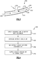
- FIG. 4 illustrates a flowchart 300 showing a general process for providing cooling air to the first turbine stage using the apparatus of Figure 2 .
- the discharge air is directed to the heat exchanger 140 in a "Direct Discharge Air to Heat Exchanger” step 310.
- the heat exchanger 140 overcools the actively cooled air using any known heat exchange technique in an "Overcool Actively Cooled Air” step 320.
- the overcooled air is then mixed with direct discharge air in a "Mix Actively Cooled Air with Discharge Air” step 330.
- the mixed air is then provided as cooling air to the first stage of the high pressure turbine 54 in a "Supply Cooled Cooling Air to Turbine Stage” step 340.
- the buffer heat exchanger 140 cools the actively cooled air 134 to be within a temperature range required to adequately cool the bearing compartment 160.
- the temperature required to adequately cool the bearing compartment 160 is lower than the optimum temperature range required to cool the first turbine stage in the high pressure turbine 54.
- the turbine cooling air is cooler than required for properly cooling the turbine first stage. In this situation, the turbine cooling air is referred to as being overcooled.
- the amount of overcooled cooling airflow 144 passing through the heat exchanger 140 in the illustrated example is less than the total volume of air required for cooling the corresponding turbine stage.
- a portion of the compressor section discharge air 150 is combined with the overcooled cooling airflow 144 in the mixing plenum 152 as described above.
- the addition of the compressor discharge air 150 to the overcooled cooling airflow 144 raises the end temperature of the mixed cooling air 154 and increases the volume of the mixed cooling air 154 to desired levels.
- the mixing plenum 152 is sized such that mixed cooling air 154 exiting the mixing plenum is fully mixed with an even temperature and flow characteristic at an exit of the mixing plenum. As a result, a steady stream of mixed cooling air 154 having a single temperature is directed onto the corresponding turbine stage.
- the resultant temperature and volume of the mixed cooling air 154 can be controlled or adjusted in order to achieve a desired volume and temperature for the air cooling the corresponding turbine stage.
- the amount of overcooled cooling airflow 144 output by the buffer heat exchanger 140 is set at a single volume during manufacturing of the gas turbine engine 20.
- the volume of airflow in the overcooled cooling airflow 144, and thus the temperature and volume of the mixed air 154 can be reduced or increased by the controller 190 during operation of the gas turbine engine in response to engine conditions, atmospheric conditions, or any other conditions.
- a controllable valve structure is installed at the cooling air exit 132, the overcooled airflow 144 exit from the heat exchanger 140, or both.
- the controllable valve structure is connected to the controller 190 allowing the controllable valve structure to adjust a volume of air passing through the controllable valve structure.
Landscapes
- Engineering & Computer Science (AREA)
- Mechanical Engineering (AREA)
- General Engineering & Computer Science (AREA)
- Chemical & Material Sciences (AREA)
- Combustion & Propulsion (AREA)
- Control Of Turbines (AREA)
- Turbine Rotor Nozzle Sealing (AREA)
Claims (10)
- Moteur de turbine à gaz (20) comprenant :une section de compresseur (24) comportant une pluralité d'étages de compresseur,une chambre de combustion (56) disposée à l'intérieur d'une section de chambre de combustion (26), dans lequel la section de chambre de combustion (26) est reliée fluidiquement à la section de compresseur (24),une section de turbine (28) reliée fluidiquement à la chambre de combustion (56), ladite section de turbine (28) comportant au moins un étage,une sortie d'air de refroidissement (132) disposée sur une paroi de ladite section de chambre de combustion (26),une première voie de passage de fluide reliant ladite sortie d'air de refroidissement (132) à une entrée d'un échangeur de chaleur (140),une seconde voie de passage de fluide reliant une première sortie dudit échangeur de chaleur (140) à un système d'injection de turbine (148),une ouverture (136 ; 212) reliant fluidiquement ledit système d'injection de turbine (148) à ladite section de chambre de combustion (26),un plénum de mélange (152 ; 214) en aval de ladite ouverture (136 ; 212), ledit plénum de mélange (152 ; 214) étant disposé entre une sortie dudit système d'injection de turbine (148) et ladite section de turbine (28) ; etun dispositif de commande (190) couplé de manière contrôlable audit échangeur de chaleur (140) et pouvant fonctionner pour commander les opérations de refroidissement dudit échangeur de chaleur (140) ;dans lequel l'échangeur de chaleur (140) comprend en outre une seconde sortie, et dans lequel ladite seconde sortie est reliée de manière fluide à au moins un autre composant de moteur (160), fournissant ainsi de l'air de refroidissement à l'au moins un autre composant de moteur (160) ;et caractérisé en ce quela turbine à gaz comprend en outre au moins une soupape disposée dans ladite sortie d'air de refroidissement (132) et une soupape disposée dans ladite ouverture (136 ; 212).
- Moteur à turbine à gaz selon la revendication 1, dans lequel la sortie d'air de refroidissement est disposée sur une paroi radialement extérieure de la section de chambre de combustion (26).
- Moteur à turbine à gaz selon la revendication 1 ou 2, dans lequel l'au moins un autre composant de moteur comprend un compartiment de palier de moteur (160).
- Moteur à turbine à gaz selon une quelconque revendication précédente, dans lequel l'air entrant dans ledit système d'injection de turbine (148) provenant dudit échangeur de chaleur (140) est au-dessous d'une première température seuil et l'air entrant dans ledit système d'injection de turbine (148) à travers ladite ouverture (136 ; 212) est au-dessus d'une seconde température seuil, la seconde température seuil étant supérieure à la première température seuil.
- Moteur à turbine à gaz selon la revendication 4, dans lequel l'air sortant dudit plénum de mélange (152 ; 214) est à une température entre le premier seuil et le second seuil.
- Moteur à turbine à gaz selon une quelconque revendication précédente dans lequel au moins l'une parmi ladite soupape disposée dans ladite sortie d'air de refroidissement et ladite soupape disposée dans ladite ouverture (136 ; 212) est couplée de manière contrôlable audit dispositif de commande (190).
- Procédé de fourniture d'air de refroidissement à un étage de turbine dans un moteur à turbine à gaz (20) selon une quelconque revendication précédente, comprenant :l'extraction d'air d'une section de chambre de combustion (26),le refroidissement dudit air à l'aide d'un échangeur de chaleur (140),la fourniture d'une première partie dudit air à un plénum de refroidissement (152 ; 214),le mélange de ladite première partie dudit air avec de l'air de la chambre de combustion dans ledit plénum de refroidissement
(152 ; 214), ce qui permet d'atteindre une température d'air de refroidissement souhaitée etla fourniture d'une seconde partie dudit air à au moins un autre composant (160) du moteur à turbine à gaz (20) provenant directement dudit échangeur de chaleur (140). - Procédé selon la revendication 7, dans lequel le mélange de ladite première partie dudit air avec de l'air de la chambre de combustion dans ledit plénum de refroidissement (152 ; 214) comprend la réception d'air provenant directement de ladite section de chambre de combustion (26) à travers une ouverture du système d'injection de turbine (136 ; 212) en amont dudit plénum de mélange (152 ; 214).
- Procédé selon la revendication 7 ou 8, dans lequel le refroidissement dudit air à l'aide d'un échangeur de chaleur (140) comprend un surrefroidissement dudit air en dessous d'une première température seuil, dans lequel la première température seuil est une température minimale requise pour fournir un refroidissement complet d'au moins un étage de turbine sans surrefroidir l'au moins un étage de turbine.
- Procédé selon la revendication 7, 8 ou 9, comprenant le mélange de ladite première partie dudit air avec de l'air de chambre de combustion dans ledit plénum de refroidissement (152 ; 214), ce qui permet d'atteindre une température d'air de refroidissement souhaitée, qui comprend le mélange d'air surrefroidi dudit échangeur de chaleur (140) avec de l'air provenant directement de ladite section de chambre de combustion (26).
Applications Claiming Priority (1)
| Application Number | Priority Date | Filing Date | Title |
|---|---|---|---|
| US201462008805P | 2014-06-06 | 2014-06-06 |
Publications (2)
| Publication Number | Publication Date |
|---|---|
| EP2952681A1 EP2952681A1 (fr) | 2015-12-09 |
| EP2952681B1 true EP2952681B1 (fr) | 2020-05-06 |
Family
ID=53487178
Family Applications (1)
| Application Number | Title | Priority Date | Filing Date |
|---|---|---|---|
| EP15170840.1A Active EP2952681B1 (fr) | 2014-06-06 | 2015-06-05 | Refroidissement d'un etage de turbine et procédé correspondant |
Country Status (2)
| Country | Link |
|---|---|
| US (2) | US10018360B2 (fr) |
| EP (1) | EP2952681B1 (fr) |
Families Citing this family (27)
| Publication number | Priority date | Publication date | Assignee | Title |
|---|---|---|---|---|
| US10018360B2 (en) * | 2014-06-06 | 2018-07-10 | United Technologies Corporation | Turbine stage cooling |
| US11808210B2 (en) | 2015-02-12 | 2023-11-07 | Rtx Corporation | Intercooled cooling air with heat exchanger packaging |
| US10731560B2 (en) | 2015-02-12 | 2020-08-04 | Raytheon Technologies Corporation | Intercooled cooling air |
| US10371055B2 (en) | 2015-02-12 | 2019-08-06 | United Technologies Corporation | Intercooled cooling air using cooling compressor as starter |
| US10830148B2 (en) | 2015-04-24 | 2020-11-10 | Raytheon Technologies Corporation | Intercooled cooling air with dual pass heat exchanger |
| US10221862B2 (en) | 2015-04-24 | 2019-03-05 | United Technologies Corporation | Intercooled cooling air tapped from plural locations |
| US10480419B2 (en) | 2015-04-24 | 2019-11-19 | United Technologies Corporation | Intercooled cooling air with plural heat exchangers |
| US10100739B2 (en) | 2015-05-18 | 2018-10-16 | United Technologies Corporation | Cooled cooling air system for a gas turbine engine |
| US10794288B2 (en) | 2015-07-07 | 2020-10-06 | Raytheon Technologies Corporation | Cooled cooling air system for a turbofan engine |
| JP6554736B2 (ja) * | 2015-10-23 | 2019-08-07 | 三菱日立パワーシステムズ株式会社 | ガスタービンロータ、ガスタービン、及びガスタービン設備 |
| JP6563312B2 (ja) * | 2015-11-05 | 2019-08-21 | 川崎重工業株式会社 | ガスタービンエンジンの抽気構造 |
| US10443508B2 (en) | 2015-12-14 | 2019-10-15 | United Technologies Corporation | Intercooled cooling air with auxiliary compressor control |
| US9988928B2 (en) * | 2016-05-17 | 2018-06-05 | Siemens Energy, Inc. | Systems and methods for determining turbomachine engine safe start clearances following a shutdown of the turbomachine engine |
| US10669940B2 (en) | 2016-09-19 | 2020-06-02 | Raytheon Technologies Corporation | Gas turbine engine with intercooled cooling air and turbine drive |
| US10550768B2 (en) | 2016-11-08 | 2020-02-04 | United Technologies Corporation | Intercooled cooled cooling integrated air cycle machine |
| US10794290B2 (en) | 2016-11-08 | 2020-10-06 | Raytheon Technologies Corporation | Intercooled cooled cooling integrated air cycle machine |
| US10961911B2 (en) | 2017-01-17 | 2021-03-30 | Raytheon Technologies Corporation | Injection cooled cooling air system for a gas turbine engine |
| US10995673B2 (en) | 2017-01-19 | 2021-05-04 | Raytheon Technologies Corporation | Gas turbine engine with intercooled cooling air and dual towershaft accessory gearbox |
| US10577964B2 (en) | 2017-03-31 | 2020-03-03 | United Technologies Corporation | Cooled cooling air for blade air seal through outer chamber |
| US10711640B2 (en) | 2017-04-11 | 2020-07-14 | Raytheon Technologies Corporation | Cooled cooling air to blade outer air seal passing through a static vane |
| US11268444B2 (en) * | 2017-05-18 | 2022-03-08 | Raytheon Technologies Corporation | Turbine cooling arrangement |
| US10738703B2 (en) | 2018-03-22 | 2020-08-11 | Raytheon Technologies Corporation | Intercooled cooling air with combined features |
| US10808619B2 (en) | 2018-04-19 | 2020-10-20 | Raytheon Technologies Corporation | Intercooled cooling air with advanced cooling system |
| US10830145B2 (en) | 2018-04-19 | 2020-11-10 | Raytheon Technologies Corporation | Intercooled cooling air fleet management system |
| US10718233B2 (en) | 2018-06-19 | 2020-07-21 | Raytheon Technologies Corporation | Intercooled cooling air with low temperature bearing compartment air |
| US11255268B2 (en) | 2018-07-31 | 2022-02-22 | Raytheon Technologies Corporation | Intercooled cooling air with selective pressure dump |
| US12320299B2 (en) * | 2022-07-20 | 2025-06-03 | General Electric Company | Cooling air delivery system and methods thereof |
Family Cites Families (18)
| Publication number | Priority date | Publication date | Assignee | Title |
|---|---|---|---|---|
| US6644012B2 (en) | 2001-11-02 | 2003-11-11 | Alston (Switzerland) Ltd | Gas turbine set |
| US7823389B2 (en) | 2006-11-15 | 2010-11-02 | General Electric Company | Compound clearance control engine |
| US8495883B2 (en) | 2007-04-05 | 2013-07-30 | Siemens Energy, Inc. | Cooling of turbine components using combustor shell air |
| US7954324B2 (en) * | 2007-04-05 | 2011-06-07 | Siemens Energy, Inc. | Gas turbine engine |
| US8056345B2 (en) * | 2007-06-13 | 2011-11-15 | United Technologies Corporation | Hybrid cooling of a gas turbine engine |
| US20090074589A1 (en) * | 2007-09-18 | 2009-03-19 | Biao Fang | Cooling Circuit for Enhancing Turbine Performance |
| US7827795B2 (en) * | 2008-09-19 | 2010-11-09 | Woodward Governor Company | Active thermal protection for fuel injectors |
| US9038398B2 (en) | 2012-02-27 | 2015-05-26 | United Technologies Corporation | Gas turbine engine buffer cooling system |
| US9157325B2 (en) | 2012-02-27 | 2015-10-13 | United Technologies Corporation | Buffer cooling system providing gas turbine engine architecture cooling |
| US10012098B2 (en) * | 2012-02-29 | 2018-07-03 | Siemens Energy, Inc. | Mid-section of a can-annular gas turbine engine to introduce a radial velocity component into an air flow discharged from a compressor of the mid-section |
| US8893510B2 (en) * | 2012-11-07 | 2014-11-25 | Siemens Aktiengesellschaft | Air injection system in a gas turbine engine |
| US20140126991A1 (en) | 2012-11-07 | 2014-05-08 | General Electric Company | Systems and methods for active component life management for gas turbine engines |
| US20140123666A1 (en) | 2012-11-07 | 2014-05-08 | General Electric Company | System to Improve Gas Turbine Output and Hot Gas Path Component Life Utilizing Humid Air for Nozzle Over Cooling |
| US9334803B2 (en) * | 2013-08-20 | 2016-05-10 | General Electric Company | Method of recovering energy in a steam-cooled gas turbine |
| WO2015112215A2 (fr) * | 2013-11-04 | 2015-07-30 | United Technologies Corporation | Système d'injection de carburnat refroidi pour moteur à turbine à gaz |
| US10024238B2 (en) | 2014-04-03 | 2018-07-17 | United Technologies Corporation | Cooling system with a bearing compartment bypass |
| US10018360B2 (en) * | 2014-06-06 | 2018-07-10 | United Technologies Corporation | Turbine stage cooling |
| US10415478B2 (en) * | 2015-01-20 | 2019-09-17 | United Technologies Corporation | Air mixing systems having mixing chambers for gas turbine engines |
-
2015
- 2015-06-02 US US14/728,991 patent/US10018360B2/en active Active
- 2015-06-05 EP EP15170840.1A patent/EP2952681B1/fr active Active
-
2018
- 2018-06-06 US US16/001,349 patent/US10808933B2/en active Active
Non-Patent Citations (1)
| Title |
|---|
| None * |
Also Published As
| Publication number | Publication date |
|---|---|
| EP2952681A1 (fr) | 2015-12-09 |
| US20150354822A1 (en) | 2015-12-10 |
| US20180347815A1 (en) | 2018-12-06 |
| US10808933B2 (en) | 2020-10-20 |
| US10018360B2 (en) | 2018-07-10 |
Similar Documents
| Publication | Publication Date | Title |
|---|---|---|
| EP2952681B1 (fr) | Refroidissement d'un etage de turbine et procédé correspondant | |
| EP2952698B1 (fr) | Refroidissement d'un étage de turbine | |
| EP3106646B1 (fr) | Moteur à double flux avec un système d'air de refroidissement et procédé correspondant | |
| EP3296543B1 (fr) | Moteur à turbine à gaz avec air de refroidissement refroidi et entraînement de turbine | |
| US11236639B2 (en) | Gas turbine engine and an airflow control system | |
| US9879602B2 (en) | Compressed air bleed supply for buffer system | |
| EP2957746B1 (fr) | Refroidissement de turbine haute pression | |
| EP3690213B1 (fr) | Contrôle environnemental d'un aéronef | |
| EP3039264B1 (fr) | Agencement de refroidissement et de mélange de diffuseur de turbine à gaz | |
| US10323524B2 (en) | Axial skin core cooling passage for a turbine engine component | |
| US10526910B2 (en) | Gas turbine engine nacelle ventilation manifold for cooling accessories | |
| EP3348810B1 (fr) | Système d'air de refroidissement refroidi par injection pour moteur à turbine à gaz et procédé correspondant | |
| EP3126640B1 (fr) | Contrôle actif des jeux pour moteur à turbine à gaz | |
| US20160208692A1 (en) | Gas turbine engine with a multi-spool driven fan | |
| EP3805527B1 (fr) | Air de refroidissement refroidi pour joint d'air de lame à travers une chambre externe | |
| EP3287620B1 (fr) | Compresseur pour circuit de refroidissement de moteur | |
| EP3056668B1 (fr) | Conditionnement thermique de rotor de compresseur à haute pression au moyen d'air refroidi conditionné | |
| EP3358152B1 (fr) | Chambre de mélange externe pour moteur à turbine à gaz avec de l'air de refroidissement de turbine refroidi | |
| EP3832071B1 (fr) | Circuit d'écoulement de moteur à turbine à gaz comprenant des trous de flux de refroidissement vectorisés | |
| EP3647563B1 (fr) | Commande de moteur à turbine à gaz basée sur la caractéristique d'air refroidi | |
| EP3348812B1 (fr) | Air de refroidissement de moteur à turbine à gaz avec décharge d'air froid | |
| EP3179034B1 (fr) | Air de refroidissement à plusieurs sources pour une turbine |
Legal Events
| Date | Code | Title | Description |
|---|---|---|---|
| PUAI | Public reference made under article 153(3) epc to a published international application that has entered the european phase |
Free format text: ORIGINAL CODE: 0009012 |
|
| AK | Designated contracting states |
Kind code of ref document: A1 Designated state(s): AL AT BE BG CH CY CZ DE DK EE ES FI FR GB GR HR HU IE IS IT LI LT LU LV MC MK MT NL NO PL PT RO RS SE SI SK SM TR |
|
| AX | Request for extension of the european patent |
Extension state: BA ME |
|
| 17P | Request for examination filed |
Effective date: 20160608 |
|
| RBV | Designated contracting states (corrected) |
Designated state(s): AL AT BE BG CH CY CZ DE DK EE ES FI FR GB GR HR HU IE IS IT LI LT LU LV MC MK MT NL NO PL PT RO RS SE SI SK SM TR |
|
| RAP1 | Party data changed (applicant data changed or rights of an application transferred) |
Owner name: UNITED TECHNOLOGIES CORPORATION |
|
| STAA | Information on the status of an ep patent application or granted ep patent |
Free format text: STATUS: EXAMINATION IS IN PROGRESS |
|
| 17Q | First examination report despatched |
Effective date: 20180530 |
|
| GRAP | Despatch of communication of intention to grant a patent |
Free format text: ORIGINAL CODE: EPIDOSNIGR1 |
|
| STAA | Information on the status of an ep patent application or granted ep patent |
Free format text: STATUS: GRANT OF PATENT IS INTENDED |
|
| INTG | Intention to grant announced |
Effective date: 20191213 |
|
| GRAS | Grant fee paid |
Free format text: ORIGINAL CODE: EPIDOSNIGR3 |
|
| GRAA | (expected) grant |
Free format text: ORIGINAL CODE: 0009210 |
|
| STAA | Information on the status of an ep patent application or granted ep patent |
Free format text: STATUS: THE PATENT HAS BEEN GRANTED |
|
| AK | Designated contracting states |
Kind code of ref document: B1 Designated state(s): AL AT BE BG CH CY CZ DE DK EE ES FI FR GB GR HR HU IE IS IT LI LT LU LV MC MK MT NL NO PL PT RO RS SE SI SK SM TR |
|
| REG | Reference to a national code |
Ref country code: GB Ref legal event code: FG4D |
|
| REG | Reference to a national code |
Ref country code: CH Ref legal event code: EP Ref country code: AT Ref legal event code: REF Ref document number: 1267010 Country of ref document: AT Kind code of ref document: T Effective date: 20200515 |
|
| REG | Reference to a national code |
Ref country code: IE Ref legal event code: FG4D |
|
| REG | Reference to a national code |
Ref country code: DE Ref legal event code: R096 Ref document number: 602015052017 Country of ref document: DE |
|
| REG | Reference to a national code |
Ref country code: LT Ref legal event code: MG4D |
|
| REG | Reference to a national code |
Ref country code: NL Ref legal event code: MP Effective date: 20200506 |
|
| PG25 | Lapsed in a contracting state [announced via postgrant information from national office to epo] |
Ref country code: NO Free format text: LAPSE BECAUSE OF FAILURE TO SUBMIT A TRANSLATION OF THE DESCRIPTION OR TO PAY THE FEE WITHIN THE PRESCRIBED TIME-LIMIT Effective date: 20200806 Ref country code: FI Free format text: LAPSE BECAUSE OF FAILURE TO SUBMIT A TRANSLATION OF THE DESCRIPTION OR TO PAY THE FEE WITHIN THE PRESCRIBED TIME-LIMIT Effective date: 20200506 Ref country code: LT Free format text: LAPSE BECAUSE OF FAILURE TO SUBMIT A TRANSLATION OF THE DESCRIPTION OR TO PAY THE FEE WITHIN THE PRESCRIBED TIME-LIMIT Effective date: 20200506 Ref country code: IS Free format text: LAPSE BECAUSE OF FAILURE TO SUBMIT A TRANSLATION OF THE DESCRIPTION OR TO PAY THE FEE WITHIN THE PRESCRIBED TIME-LIMIT Effective date: 20200906 Ref country code: GR Free format text: LAPSE BECAUSE OF FAILURE TO SUBMIT A TRANSLATION OF THE DESCRIPTION OR TO PAY THE FEE WITHIN THE PRESCRIBED TIME-LIMIT Effective date: 20200807 Ref country code: SE Free format text: LAPSE BECAUSE OF FAILURE TO SUBMIT A TRANSLATION OF THE DESCRIPTION OR TO PAY THE FEE WITHIN THE PRESCRIBED TIME-LIMIT Effective date: 20200506 Ref country code: PT Free format text: LAPSE BECAUSE OF FAILURE TO SUBMIT A TRANSLATION OF THE DESCRIPTION OR TO PAY THE FEE WITHIN THE PRESCRIBED TIME-LIMIT Effective date: 20200907 |
|
| PG25 | Lapsed in a contracting state [announced via postgrant information from national office to epo] |
Ref country code: BG Free format text: LAPSE BECAUSE OF FAILURE TO SUBMIT A TRANSLATION OF THE DESCRIPTION OR TO PAY THE FEE WITHIN THE PRESCRIBED TIME-LIMIT Effective date: 20200806 Ref country code: RS Free format text: LAPSE BECAUSE OF FAILURE TO SUBMIT A TRANSLATION OF THE DESCRIPTION OR TO PAY THE FEE WITHIN THE PRESCRIBED TIME-LIMIT Effective date: 20200506 Ref country code: LV Free format text: LAPSE BECAUSE OF FAILURE TO SUBMIT A TRANSLATION OF THE DESCRIPTION OR TO PAY THE FEE WITHIN THE PRESCRIBED TIME-LIMIT Effective date: 20200506 Ref country code: HR Free format text: LAPSE BECAUSE OF FAILURE TO SUBMIT A TRANSLATION OF THE DESCRIPTION OR TO PAY THE FEE WITHIN THE PRESCRIBED TIME-LIMIT Effective date: 20200506 |
|
| REG | Reference to a national code |
Ref country code: AT Ref legal event code: MK05 Ref document number: 1267010 Country of ref document: AT Kind code of ref document: T Effective date: 20200506 |
|
| PG25 | Lapsed in a contracting state [announced via postgrant information from national office to epo] |
Ref country code: NL Free format text: LAPSE BECAUSE OF FAILURE TO SUBMIT A TRANSLATION OF THE DESCRIPTION OR TO PAY THE FEE WITHIN THE PRESCRIBED TIME-LIMIT Effective date: 20200506 Ref country code: AL Free format text: LAPSE BECAUSE OF FAILURE TO SUBMIT A TRANSLATION OF THE DESCRIPTION OR TO PAY THE FEE WITHIN THE PRESCRIBED TIME-LIMIT Effective date: 20200506 |
|
| PG25 | Lapsed in a contracting state [announced via postgrant information from national office to epo] |
Ref country code: ES Free format text: LAPSE BECAUSE OF FAILURE TO SUBMIT A TRANSLATION OF THE DESCRIPTION OR TO PAY THE FEE WITHIN THE PRESCRIBED TIME-LIMIT Effective date: 20200506 Ref country code: DK Free format text: LAPSE BECAUSE OF FAILURE TO SUBMIT A TRANSLATION OF THE DESCRIPTION OR TO PAY THE FEE WITHIN THE PRESCRIBED TIME-LIMIT Effective date: 20200506 Ref country code: IT Free format text: LAPSE BECAUSE OF FAILURE TO SUBMIT A TRANSLATION OF THE DESCRIPTION OR TO PAY THE FEE WITHIN THE PRESCRIBED TIME-LIMIT Effective date: 20200506 Ref country code: SM Free format text: LAPSE BECAUSE OF FAILURE TO SUBMIT A TRANSLATION OF THE DESCRIPTION OR TO PAY THE FEE WITHIN THE PRESCRIBED TIME-LIMIT Effective date: 20200506 Ref country code: EE Free format text: LAPSE BECAUSE OF FAILURE TO SUBMIT A TRANSLATION OF THE DESCRIPTION OR TO PAY THE FEE WITHIN THE PRESCRIBED TIME-LIMIT Effective date: 20200506 Ref country code: CZ Free format text: LAPSE BECAUSE OF FAILURE TO SUBMIT A TRANSLATION OF THE DESCRIPTION OR TO PAY THE FEE WITHIN THE PRESCRIBED TIME-LIMIT Effective date: 20200506 Ref country code: AT Free format text: LAPSE BECAUSE OF FAILURE TO SUBMIT A TRANSLATION OF THE DESCRIPTION OR TO PAY THE FEE WITHIN THE PRESCRIBED TIME-LIMIT Effective date: 20200506 Ref country code: RO Free format text: LAPSE BECAUSE OF FAILURE TO SUBMIT A TRANSLATION OF THE DESCRIPTION OR TO PAY THE FEE WITHIN THE PRESCRIBED TIME-LIMIT Effective date: 20200506 |
|
| REG | Reference to a national code |
Ref country code: CH Ref legal event code: PL |
|
| REG | Reference to a national code |
Ref country code: DE Ref legal event code: R097 Ref document number: 602015052017 Country of ref document: DE |
|
| PG25 | Lapsed in a contracting state [announced via postgrant information from national office to epo] |
Ref country code: MC Free format text: LAPSE BECAUSE OF FAILURE TO SUBMIT A TRANSLATION OF THE DESCRIPTION OR TO PAY THE FEE WITHIN THE PRESCRIBED TIME-LIMIT Effective date: 20200506 Ref country code: PL Free format text: LAPSE BECAUSE OF FAILURE TO SUBMIT A TRANSLATION OF THE DESCRIPTION OR TO PAY THE FEE WITHIN THE PRESCRIBED TIME-LIMIT Effective date: 20200506 Ref country code: SK Free format text: LAPSE BECAUSE OF FAILURE TO SUBMIT A TRANSLATION OF THE DESCRIPTION OR TO PAY THE FEE WITHIN THE PRESCRIBED TIME-LIMIT Effective date: 20200506 |
|
| PLBE | No opposition filed within time limit |
Free format text: ORIGINAL CODE: 0009261 |
|
| STAA | Information on the status of an ep patent application or granted ep patent |
Free format text: STATUS: NO OPPOSITION FILED WITHIN TIME LIMIT |
|
| RAP2 | Party data changed (patent owner data changed or rights of a patent transferred) |
Owner name: RAYTHEON TECHNOLOGIES CORPORATION |
|
| PG25 | Lapsed in a contracting state [announced via postgrant information from national office to epo] |
Ref country code: LU Free format text: LAPSE BECAUSE OF NON-PAYMENT OF DUE FEES Effective date: 20200605 |
|
| 26N | No opposition filed |
Effective date: 20210209 |
|
| REG | Reference to a national code |
Ref country code: BE Ref legal event code: MM Effective date: 20200630 |
|
| PG25 | Lapsed in a contracting state [announced via postgrant information from national office to epo] |
Ref country code: IE Free format text: LAPSE BECAUSE OF NON-PAYMENT OF DUE FEES Effective date: 20200605 Ref country code: CH Free format text: LAPSE BECAUSE OF NON-PAYMENT OF DUE FEES Effective date: 20200630 Ref country code: LI Free format text: LAPSE BECAUSE OF NON-PAYMENT OF DUE FEES Effective date: 20200630 |
|
| PG25 | Lapsed in a contracting state [announced via postgrant information from national office to epo] |
Ref country code: SI Free format text: LAPSE BECAUSE OF FAILURE TO SUBMIT A TRANSLATION OF THE DESCRIPTION OR TO PAY THE FEE WITHIN THE PRESCRIBED TIME-LIMIT Effective date: 20200506 Ref country code: BE Free format text: LAPSE BECAUSE OF NON-PAYMENT OF DUE FEES Effective date: 20200630 |
|
| PG25 | Lapsed in a contracting state [announced via postgrant information from national office to epo] |
Ref country code: TR Free format text: LAPSE BECAUSE OF FAILURE TO SUBMIT A TRANSLATION OF THE DESCRIPTION OR TO PAY THE FEE WITHIN THE PRESCRIBED TIME-LIMIT Effective date: 20200506 Ref country code: MT Free format text: LAPSE BECAUSE OF FAILURE TO SUBMIT A TRANSLATION OF THE DESCRIPTION OR TO PAY THE FEE WITHIN THE PRESCRIBED TIME-LIMIT Effective date: 20200506 Ref country code: CY Free format text: LAPSE BECAUSE OF FAILURE TO SUBMIT A TRANSLATION OF THE DESCRIPTION OR TO PAY THE FEE WITHIN THE PRESCRIBED TIME-LIMIT Effective date: 20200506 |
|
| PG25 | Lapsed in a contracting state [announced via postgrant information from national office to epo] |
Ref country code: MK Free format text: LAPSE BECAUSE OF FAILURE TO SUBMIT A TRANSLATION OF THE DESCRIPTION OR TO PAY THE FEE WITHIN THE PRESCRIBED TIME-LIMIT Effective date: 20200506 |
|
| P01 | Opt-out of the competence of the unified patent court (upc) registered |
Effective date: 20230520 |
|
| PGFP | Annual fee paid to national office [announced via postgrant information from national office to epo] |
Ref country code: DE Payment date: 20250520 Year of fee payment: 11 |
|
| PGFP | Annual fee paid to national office [announced via postgrant information from national office to epo] |
Ref country code: GB Payment date: 20250520 Year of fee payment: 11 |
|
| PGFP | Annual fee paid to national office [announced via postgrant information from national office to epo] |
Ref country code: FR Payment date: 20250520 Year of fee payment: 11 |
|
| REG | Reference to a national code |
Ref country code: DE Ref legal event code: R081 Ref document number: 602015052017 Country of ref document: DE Owner name: RTX CORPORATION (N.D.GES.D. STAATES DELAWARE),, US Free format text: FORMER OWNER: UNITED TECHNOLOGIES CORPORATION, FARMINGTON, CONN., US |