EP2957702A1 - Türschwellensystem für eine haustür, eine ladentür oder dergleichen - Google Patents
Türschwellensystem für eine haustür, eine ladentür oder dergleichen Download PDFInfo
- Publication number
- EP2957702A1 EP2957702A1 EP15169455.1A EP15169455A EP2957702A1 EP 2957702 A1 EP2957702 A1 EP 2957702A1 EP 15169455 A EP15169455 A EP 15169455A EP 2957702 A1 EP2957702 A1 EP 2957702A1
- Authority
- EP
- European Patent Office
- Prior art keywords
- door
- profile
- sill system
- door sill
- adapter
- Prior art date
- Legal status (The legal status is an assumption and is not a legal conclusion. Google has not performed a legal analysis and makes no representation as to the accuracy of the status listed.)
- Granted
Links
Images


Classifications
-
- E—FIXED CONSTRUCTIONS
- E06—DOORS, WINDOWS, SHUTTERS, OR ROLLER BLINDS IN GENERAL; LADDERS
- E06B—FIXED OR MOVABLE CLOSURES FOR OPENINGS IN BUILDINGS, VEHICLES, FENCES OR LIKE ENCLOSURES IN GENERAL, e.g. DOORS, WINDOWS, BLINDS, GATES
- E06B3/00—Window sashes, door leaves, or like elements for closing wall or like openings; Layout of fixed or moving closures, e.g. windows in wall or like openings; Features of rigidly-mounted outer frames relating to the mounting of wing frames
- E06B3/96—Corner joints or edge joints for windows, doors, or the like frames or wings
- E06B3/9632—Corner joints or edge joints for windows, doors, or the like frames or wings between a jamb and the threshold or sill of window or door frames
-
- E—FIXED CONSTRUCTIONS
- E06—DOORS, WINDOWS, SHUTTERS, OR ROLLER BLINDS IN GENERAL; LADDERS
- E06B—FIXED OR MOVABLE CLOSURES FOR OPENINGS IN BUILDINGS, VEHICLES, FENCES OR LIKE ENCLOSURES IN GENERAL, e.g. DOORS, WINDOWS, BLINDS, GATES
- E06B1/00—Border constructions of openings in walls, floors, or ceilings; Frames to be rigidly mounted in such openings
- E06B1/70—Sills; Thresholds
- E06B2001/707—Thresholds with special provision for insulation
Definitions
- the invention relates to a door sill system for a front door, a shop door or the like comprising a door frame with a revolving door wing, wherein on the vertically arranged profile element of the door frame, a thermally separated door threshold, consisting of a base profile with attached cover profile is adapted to the lower revolving door leaf profile in closed state of the door sealingly cooperates.
- Threshold bindings are known with which particularly flat-built door sill profiles between the spars of frames and windows can be integrated. So-called. Threshold adapter are known from the prior art, by means of the threshold profile can be easily and stably set between the spars.
- the known threshold adapter in this case consists of an angle profile whose horizontal leg corresponds to the profiling of the door sill, which essentially consists of an upper tread area and a front, to the outside facing ramp area.
- the vertically extending leg of the threshold adapter in this case has a plate-shaped support member, which is intended to be fixed to the inwardly facing rebate area of the spar profile.
- the invention thus presents the problem of providing a door sill system for a front door, a shop door or the like, which makes it possible to provide or convert a conventional revolving door with door sill frame so that it is a barrier-free front door or shop door to produce.
- an attachment profile on the one hand and to the revolving door leaf profile an adapter profile on the other hand can be mounted, which compensate in the threshold area the door sill and the stop of the revolving door leaf profile to form a gap.
- a drainage profile made of aluminum is placed on the existing threshold with a drainage slope of at least 3 °.
- the dewatering profile can be placed or positioned in an adapted contour on the existing door sill with a double-sided adhesive tape.
- the drainage profile which contains at least two drainage channels, is constructed in such a way that the outer channel lying to the outside is provided with drainage holes or drainage slots below the door threshold or outside the building seal.
- the rainwater drainage can also be done through holes and opening slots horizontally outwards. In this case, for drainage outside the building seal a water-permeable layer below the water outlet to arrange or provide a channel.
- the Endkappencovere be contour consistent with the drainage profile each end to the attachment profile to the door sill and the door frame arranged.
- the pair of end caps with adapted shaping is designed as a water outlet and in this case derives the accumulated water to the outside from all the drainage chambers of the attachment profile, the resulting water being discharged horizontally or vertically.
- the so-called. Bodendichtungsadapterprofil below the door leaf is formed here thermally separated.
- aluminum is preferably provided on the outside and a PVC profile on the inside, wherein in the PVC profile a Absenk réelledichtung is arranged.
- the outside aluminum profile can also be provided here with a Absenk réelledichtungsprofil or alternatively with a weather protection leg with at least two brush seals.
- the adapter profile is preferably provided with at least one adhesive tape for air or water shut-off.
- the attachment profile or drainage profile can be placed on the front outboard tread profile of the door sill.
- the attachment profile adapts in the obliquely forwardly sloping tread profile in such a way that it has a vertical web wall towards the front.
- the attachment profile is provided with drainage channels, which are formed within the raw profile body as vertical webs, at the ends of each transverse webs are provided.
- the penetrating water can be absorbed into the openings of the channels, which is then discharged accordingly end.
- the attachment profile is integrated at its free ends, each with an end cap profile between the profile ends of the door frame.
- the end cap profile in this case has openings for the discharge of rainwater, which can also be derived through a hole in the ground.
- the adapter profile fills the space between the inside lying stop profile and the outside lying sash profile of the revolving door leaf profile.
- the space which faces outward on the revolving door leaf frame filled in such a way that forms a continuous gap between the door sill and the filled revolving door leaf profile with respect to the stop on the inside.
- the adapter profile is arranged flush with the front frame profile.
- at least one lowerable sealing strip is arranged, which causes a seal of the gap when closing the door.
- brush seals may also be provided on the adapter profile, which likewise seal the gap formed here between the revolving door leaf and the floor sill. It is also possible that a combination of brush seals and lowerable sealing strip can be used.
- the adapter profile is in this case formed in two parts, wherein the front, outwardly facing profile part made of aluminum and the inward profile part consists of plastic.
- the front, outwardly facing profile part made of aluminum is held correspondingly in the aluminum doorstep, wherein a heat-insulating plastic profile is arranged toward the inside.
- drainage means pieces can be used in sections in the attachment profile, via which, in particular, the water accumulating in the middle region of the door can be removed on the attachment profile.
- the dewatering center piece between the butt ends of a split attachment profile is positively integrated.
- FIGS. 1 . 2 . 3 and 4 show the door sill system according to the invention for a front door, a shop door or the like.
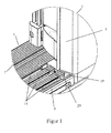
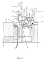
- the front door comprises a door frame 1, as it is indicated in the FIG. 2 , with a revolving door wing 2, as shown in particular from the sectional views of FIG. 2 . 3 and 4 can be seen closer.
- a thermally separated door threshold 4 consisting of a base profile 5 with attached treads 6 and 7 adapted, as this particular in the FIG. 5 are shown in more detail. From the FIG. 2 .
- FIG. 3 and 4 is closer to recognize that to provide a barrier-free door, which consists of a mounted door frame 1 with revolving door 2, on the existing door sill 4 an attachment profile 8 can be placed, as in the individual representation in the FIG. 5 is shown in more detail. Furthermore, in this case to the revolving door leaf profile 9, an adapter profile 10, as shown in the single view in the FIG. 6 is shown attached to the profiling of the revolving door wing, as in particular in the FIG. 2 . 3 and 4 will be shown.
- a barrier-free threshold 4 without threshold stop with the simplest installation can be provided on an existing threshold with outer drainage slope. It is shown that with the accessories of an attachment profile 8 and an adapter profile 10, a conventional door provided with a stop can be retrofitted or provided for a barrier-free door sill 4.
- the threshold 4 is in the level of the bottom 13, so that in the open Condition of the door is no longer an obstacle regarding the door frame construction.
- the attachment section 8 can be placed on the front, outboard tread 6 of the door sill 4.
- the attachment profile 8 is in this case provided with drainage channels 14, wherein these are formed by vertically shaped webs 15, which are bounded at the end with transverse webs 16 which lie here in the level of the soil horizon 13.
- the attachment profile 8 is in the contour 17 of the tread 6 such that it engages with its front rounding in the arc section of the tread 6, below the attachment profile 8, an adhesive tape 18 is provided with the particular attachment 8 here on the Surface of the tread 6 can be set.
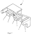
- End cap profiles 19 are provided, such as these in the FIG. 1 and 7 are shown in the perspective view.
- the end cap profile 19 is hereby added to the attachment profile 8, as it is in the FIG. 1 is shown, and it bridges the gap between the profile ends 3 of the door frame 1 and the attachment profile 8.
- this has the Einzelendkappenprofil 19 via openings 20, for the discharge of rainwater, which is particularly in the Drainage channels 14 of the attachment profile 8 is obtained.
- the accumulating water is discharged here horizontally forward, with the accumulating water can flow either into the ground, shown in the FIG. 2 and 3 , or that in the outer area a drainage 21 is provided for receiving the accumulating water, as in the FIG. 4 will be shown.
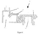
- the design of the adapter profile 10 is in the individual representation in the FIG. 6 to recognize closer, wherein the adapter profile 10 in the mounted state, shown in the FIG. 2 . 3 and 4 , the space between the inner stop profile 11 and the outer sash profile 22 of the revolving door leaf profile 9 fills.
- the adapter profile 10 is arranged with its front wall 23 flush with the sash profile 22, so that the adapter profile 10 is flush with the frame 1 of the door towards the front.
- downwardly open chambers 24 and 25 are provided, which are in particular intended to receive here lowerable sealing strips 26 and 27, as this particular in the FIG. 2 can be seen.
- the lowerable sealing strip 26 and 27 in this case moves out of the chamber 24, 25 out, so that the gap 12 is sealed in this case.
- the adapter profile 10 may also be provided on the adapter profile 10 brush sealing strips 28, which also seal the gap 12 between the threshold 4 and the revolving door leaf profile 9 in the closed state of the door here.
- the adapter profile consists of two parts, wherein the front outwardly facing profile member 29 made of aluminum and the inward profile member 30 is made of plastic. Due to this design it is achieved that the adapter profile 10 on the one hand is carried out thermally separated, in particular the outwardly facing profile member 29 is held here in aluminum, so that it has an optical binding effect to the threshold profile system.
- FIGS a particularly advantageous embodiment of the invention, shown in the FIGS.
- drainage means pieces 31 can be used in sections in the attachment profile 8, via which, in particular, the water accumulating in the middle region of the door can be removed in the attachment profile 8, which occurs in the drainage channels 14.
- the dewatering center piece 31 between the butt ends 32 and 33 of a split attachment profile 8.1 and 8.2 is positively integrated.
- the dewatering center piece 31 consists essentially of a transverse web 34 on the longitudinal webs 35 are formed, which are flush with the treads 16 of the attachment profile 8.
- Each end of the crossbar 34 molded profiles 36 and 37 are formed, which form a positive connection with the butt ends 32 and 33 of the split attachment profile 8, wherein in particular the outward mold section 37 has opened portions 38.
Landscapes
- Engineering & Computer Science (AREA)
- Civil Engineering (AREA)
- Structural Engineering (AREA)
- Specific Sealing Or Ventilating Devices For Doors And Windows (AREA)
- Wing Frames And Configurations (AREA)
- Special Wing (AREA)
Abstract
Description
- Die Erfindung betrifft ein Türschwellensystem für eine Haustür, eine Ladentür oder dergleichen, umfassend einen Türrahmen mit einem Drehtürflügel, wobei an dem senkrecht angeordneten Profilelement des Türrahmens eine thermisch getrennte Türschwelle, bestehend aus einem Basisprofil mit angesetztem Deckprofil adaptiert ist, die mit dem unteren Drehtürflügelprofil in geschlossenem Zustand der Tür dichtend zusammenwirkt.
- Aus dem Stand der Technik sind aus der
DE 20 2005 021 045.5 Schwelleneinbindungen bekannt, mit denen besonders flach bauende Türschwellenprofile zwischen die Holme von Zargen und Fenstern eingebunden werden können. So sind aus dem Stand der Technik sog. Schwellenadapter bekannt, mittels der das Schwellenprofil einfach und stabil zwischen die Holme festgelegt werden kann. Der bekannte Schwellenadapter besteht hierbei aus einem Winkelprofil, dessen waagerechter Schenkel der Profilierung der Türschwelle entspricht, die im Wesentlichen aus einem oberen Trittbereich und einem vorderen, zur Außenseite weisenden Rampenbereich besteht. Der senkrecht verlaufende Schenkel des Schwellenadapters verfügt hierbei über ein plattenförmiges Halterungselement, welches zur Festlegung an den nach innen weisenden Falzbereich des Holmprofils bestimmt ist. - Dieses aus dem Stand der Technik bekannte Türschwellensystem ist hierbei derart ausgebildet, dass insbesondere der umlaufende Anschlag an der Innenseite der Tür sich im geschlossenen Zustand der Tür auch dichtend an das untere Schwellenprofil anlegt, so dass im Schwellenbereich die Schwelle über das Bodenniveau hinausragt. Um insbesondere eine derartige nach dem Stand der Technik bekannte Tür als Haustür oder als Ladentür einzusetzen, wäre es daher erforderlich hier mit einer anderen Schwelle im Rahmensystem aufzubauen, damit ein barrierefreier Durchgang durch die Haustür oder die Ladentür erfolgen kann.
- Der Erfindung stellt sich somit das Problem, ein Türschwellensystem für eine Haustür, eine Ladentür oder dergleichen vorzuhalten, welche es ermöglicht, eine herkömmliche Drehtür mit Türschwellenrahmen derart bereitzustellen bzw. umzubauen, dass daraus eine barrierefreie Haustür oder Ladentür herstellbar ist.
- Erfindungsgemäß wird dieses Problem mit den Merkmalen des Hauptanspruchs gelöst, vorteilhafte Ausgestaltungen der Erfindung ergeben sich aus den Unteransprüchen.
- Die mit der Erfindung erreichten Vorteile bestehen nun darin, dass mit dem erfindungsgemäßen Türschwellensystem eine nach dem Stand der Technik bekannte Drehtür mit einem Schwellensystem, welches für einen Anschlag bestimmt ist, umgerüstet werden kann, so dass sie für eine barrierefreie Haus- oder Ladentür ohne Schwellenanschlag eingebaut werden kann. Dies kann mit einfachster Montage dadurch erfolgen, dass auf die vorhandene Schwelle Profilteile montierbar sind. Aufgrund dieser Ausbildung können nun durch einfache Zubehörteile die Haustür oder die Ladentür entsprechend ergänzt bzw. umgerüstet werden, so dass sie als schwellenlose Tür eingesetzt werden kann.
- Gemäß der Erfindung wird hierzu vorgeschlagen, dass zur Bereitstellung einer barrierefreien Tür bestehend aus montiertem Türrahmen mit Drehtürflügel an die vorhandene Türschwelle ein Aufsatzprofil einerseits und an das Drehtürflügelprofil ein Adapterprofil andererseits montierbar sind, welche im Schwellenbereich die Türschwelle und den Anschlag des Drehtürflügelprofils unter Bildung eines Spaltes ausgleichen.
- Dabei wird ein Entwässerungsprofil aus Aluminium auf die vorhandene Türschwelle aufgesetzt mit einer Ablaufschräge von mind. 3°. Das Entwässerungsprofil kann hierbei mit einem beidseitigen Klebeband entsprechend in angepasster Kontur auf die vorhandene Türschwelle aufgesetzt bzw. positioniert werden. Das wenigstens zwei Entwässerungskanäle enthaltene Entwässerungsprofil ist derart aufgebaut, dass der zur Außenseite liegende äußere Kanal mit Entwässerungsbohrungen oder Entwässerungsschlitzen unterhalb der Türschwelle bzw. außerhalb der Gebäudeabdichtung versehen ist. Die Regenwasserableitung kann auch durch Bohrungen und Öffnungsschlitze horizontal nach außen erfolgen. Dabei ist zur Entwässerung außerhalb der Gebäudeabdichtung eine wasserdurchlässige Schicht unterhalb des Wasserablaufes anzuordnen oder ein Kanal vorzusehen.
- Die Endkappenpaare werden hierbei konturkonform zum Entwässerungsprofil jeweils endseitig an das Aufsatzprofil zur Türschwelle und zum Türrahmen angeordnet. Das Endkappenpaar mit angepasster Formung ist als Wasserablauf ausgebildet und leitet hierbei aus allen Entwässerungskammern des Aufsatzprofils das anfallende Wasser nach außen hin ab, wobei das anfallende Wasser horizontal oder vertikal hierbei abgeleitet wird. Das sog. Bodendichtungsadapterprofil unterhalb des Türflügels ist hierbei thermisch getrennt ausgebildet. Hierzu ist an der Außenseite vorzugsweise Aluminium und an der Innenseite ein PVC-Profil vorgesehen, wobei in dem PVC-Profil eine Absenkbodendichtung angeordnet ist. Das außenseitige Aluminiumprofil kann hierbei ebenfalls zusätzlich mit einem Absenkbodendichtungsprofil oder alternativ mit einem Wetterschutzschenkel mit mindestens zwei Bürstendichtungen versehen sein. Dabei ist das Adapterprofil vorzugsweise mit mindestens einem Klebeband zur Luft- oder Wasserabsperrung versehen.
- Nach einer vorteilhaften Ausgestaltung der Erfindung ist das Aufsatzprofil bzw. Entwässerungsprofil auf das vordere nach außen liegende Trittprofil der Türschwelle aufsetzbar. Das Aufsatzprofil passt sich hierbei in das schräg nach vorne abfallende Trittprofil derart ein, dass es nach vorne hin eine senkrechte Stegwand aufweist. Dabei ist das Aufsatzprofil mit Entwässerungskanälen versehen, die innerhalb des Rohprofilkörpers als senkrecht stehende Stege eingeformt sind, an dessen Enden jeweils quer verlaufende Trittstege vorgesehen sind. Somit kann insbesondere das eindringende Wasser in die Öffnungen der Kanäle aufgenommen werden, welches dann endseitig entsprechend abgeführt wird. Hierzu ist das Aufsatzprofil an seinen freien Enden mit je einem Endkappenprofil zwischen den Profilenden des Türrahmens eingebunden. Das Endkappenprofil weist hierbei Öffnungen zur Ableitung von Regenwasser auf, welches auch durch eine Bohrung ins Erdreich abgeleitet werden kann.
- Nach einer besonders vorteilhaften Weiterbildung der Erfindung füllt das Adapterprofil den Raum zwischen dem innenseitig liegenden Anschlagprofil und dem außenseitig liegendem Flügelrahmenprofil des Drehtürflügelprofils aus. Somit wird insbesondere der Raum, der nach außen weisend am Drehtürflügelrahmen liegt, derart ausgefüllt, so dass sich in Bezug zum Anschlag auf der Innenseite ein durchgehender Spalt zwischen der Türschwelle und dem ausgefüllten Drehtürflügelprofil bildet. Dabei ist das Adapterprofil bündig zum vorderen Rahmenprofil angeordnet. In dem Adapterprofil ist zumindest eine absenkbare Dichtleiste angeordnet, die beim Schließen der Tür eine Abdichtung des Spaltes bewirkt. Alternativ können hierbei auch an dem Adapterprofil Bürstendichtungen vorgesehen sein, die ebenfalls hier den sich bildenden Spalt zwischen dem Drehtürflügel und der Bodenschwelle abdichten. Auch ist es möglich, dass eine Kombination von Bürstendichtungen und absenkbarer Dichtleiste zum Einsatz kommen kann.
- Nach einer besonders vorteilhaften Ausgestaltung der Erfindung ist das Adapterprofil hierbei zweiteilig ausgebildet, wobei das vordere, nach außen weisende Profilteil aus Aluminium und das nach innen liegende Profilteil aus Kunststoff besteht. Somit ergibt sich insbesondere ein optisch geschlossener Erscheinungsbereich von der Außenseite her, wobei dann entsprechend bei der aus Aluminium bestehenden Türschwelle auch das nach außen weisende Adapterprofil aus Aluminium gehalten ist, wobei zur Innenseite hin hier ein wärmedämmendes Kunststoffprofil angeordnet ist.
- Nach einer besonders vorteilhaften Ausgestaltung der Erfindung können in das Aufsatzprofil abschnittsweise Entwässerungsmittelstücke eingesetzt werden, über die insbesondere das im Mittelbereich der Tür anfallende Wasser auf dem Aufsatzprofil abgeführt werden kann. Hierzu wird das Entwässerungsmittelstück zwischen die Stoßenden eines geteilten Aufsatzprofils formschlüssig eingebunden.
- Ein Ausführungsbeispiel der Erfindung ist in den Zeichnungen rein schematisch dargestellt und wird nachfolgend näher beschrieben. Es zeigt
-
- Figur 1
- eine perspektivische Teilansicht eines Türrahmens im Schwellenbereich;
- Figur 2
- eine geschnittene Seitenansicht des Türschwellensystems gemäß der Erfindung in einer ersten Ausführungsform;
- Figur 3
- eine weitere geschnittene Seitenansicht des Türschwellensystems gemäß der Erfindung;
- Figur 4
- eine weitere geschnittene Seitenansicht des Türschwellensystems gemäß der
Figur 3 ; - Figur 5
- eine Detailansicht des Schwellenprofils mit Aufsatzprofil;
- Figur 6
- eine Einzeldarstellung des Adapterprofils;
- Figur 7
- eine perspektivische Darstellung und Einzelansicht des Endkappenprofils;
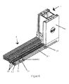
- Figur 8
- eine weitere perspektivische Teilansicht eines Türrahmens im Schwellenbereich mit einem eingefassten Entwässerungsmittelstück; und
- Figur 9
- eine perspektivische Darstellung und Einzelansicht des Entwässerungsmittelstück gemäß der
Figur 8 . - Die
Figuren 1 ,2 ,3 und4 zeigen das erfindungsgemäße Türschwellensystem für eine Haustür, eine Ladentür oder dergleichen. Dabei umfasst die Haustür einen Türrahmen 1, wie er angedeutet ist in derFigur 2 , mit einem Drehtürflügel 2, wie er insbesondere aus den geschnittenen Ansichten derFigur 2 ,3 und4 näher zu erkennen ist. Wie insbesondere aus derFigur 1 zu erkennen ist, ist an den senkrecht angeordneten Profilenden 3 des Türrahmens 1 eine thermisch getrennte Türschwelle 4, bestehend aus einem Basisprofil 5 mit aufgesetzten Trittprofilen 6 und 7 adaptiert, wie diese insbesondere in derFigur 5 näher dargestellt sind. Aus derFigur 2 ,3 und4 ist näher zu erkennen, dass zur Bereitstellung einer barrierefreien Tür, die aus einem montierten Türrahmen 1 mit Drehtürflügel 2 besteht, auf die vorhandene Türschwelle 4 ein Aufsatzprofil 8 aufsetzbar ist, wie es in der Einzeldarstellung in derFigur 5 näher gezeigt ist. Weiterhin wird hierbei an das Drehtürflügelprofil 9 ein Adapterprofil 10, wie dies in der Einzelansicht in derFigur 6 gezeigt ist, an die Profilierung des Drehtürflügels angesetzt, wie dies insbesondere in derFigur 2 ,3 und4 gezeigt wird. - Im montierten Zustand der Profile 8 und 10 ergibt sich im Schwellenbereich der Türschwelle 4, dass der Anschlag 11 des Drehtürflügelprofils 9 unter Bildung eines Spaltes 12, wie dieser insbesondere in den
Figuren 2 ,3 und4 erkennbar ist, oberhalb der Türschwelle 4 liegt. Somit kann eine barrierefreie Türschwelle 4 ohne Schwellenanschlag mit einfachster Montage auf eine vorhandene Schwelle mit äußerer Ablaufschräge bereitgestellt werden. Hierbei wird gezeigt, dass mit den Zubehörteilen eines Aufsatzprofils 8 sowie eines Adapterprofils 10 eine herkömmliche, mit einem Anschlag versehene Tür umgerüstet bzw. bereitgestellt werden kann für eine barrierefreie Türschwelle 4. Die Türschwelle 4 liegt hierbei im Niveau des Bodens 13, so dass im geöffneten Zustand der Tür kein Hindernis mehr hinsichtlich der Türrahmenkonstruktion besteht. - Wie insbesondere aus der
Figur 5 erkennbar ist, ist das Aufsatzprofil 8 auf das vordere, nach außen liegende Trittprofil 6 der Türschwelle 4 aufsetzbar. Das Aufsatzprofil 8 ist hierbei mit Entwässerungskanälen 14 versehen, wobei diese gebildet werden durch senkrecht geformte Stege 15, die endseitig mit quer laufenden Trittstegen 16 begrenzt sind, die hier im Niveau des Bodenhorizontes 13 liegen. Dabei fügt sich das Aufsatzprofil 8 in die Kontur 17 des Trittprofils 6 derart ein, dass es mit seiner vorderen Rundung in den Bogenabschnitt des Trittprofils 6 greift, wobei unterhalb des Aufsatzprofils 8 ein Klebeband 18 vorgesehen ist, mit dem insbesondere das Aufsatzprofil 8 hier auf der Fläche des Trittprofils 6 festgelegt werden kann. - Zur seitlichen Einbindung des Aufsatzprofils 8 sind sog. Endkappenprofile 19 vorgesehen, so wie diese in der
Figur 1 und7 dargestellt sind in der perspektivischen Ansicht. Das Endkappenprofil 19 wird hierbei an das Aufsatzprofil 8 angefügt, so wie es in derFigur 1 dargestellt ist, und es überbrückt hierbei den Zwischenraum zwischen den Profilenden 3 des Türrahmens 1 und dem Aufsatzprofil 8. Wie insbesondere aus der Zusammenschau derFigur 1 und derFigur 7 erkennbar ist, verfügt hierbei das Einzelendkappenprofil 19 über Öffnungen 20, zur Ableitung von Regenwasser, was insbesondere in den Entwässerungskanälen 14 des Aufsatzprofils 8 anfällt. Hierbei ist gerade in derFigur 1 zu erkennen, dass das anfallende Wasser hier horizontal nach vorne abgeführt wird, wobei das anfallende Wasser entweder in den Boden abfließen kann, dargestellt in derFigur 2 und3 , oder aber dass im Außenbereich eine Drainage 21 vorgesehen ist zur Aufnahme des anfallenden Wassers, wie es in derFigur 4 gezeigt wird. - Die Ausgestaltung des Adapterprofils 10 ist in der Einzeldarstellung in der
Figur 6 näher zu erkennen, wobei das Adapterprofil 10 im montierten Zustand, dargestellt in derFigur 2 ,3 und4 , den Raum zwischen dem innen liegenden Anschlagprofil 11 und dem außen liegenden Flügelrahmenprofil 22 des Drehtürflügelprofils 9 ausfüllt. Das Adapterprofil 10 ist mit seiner Vorderwand 23 bündig zum Flügelrahmenprofil 22 angeordnet, so dass das Adapterprofil 10 nach vorne hin bündig mit dem Rahmen 1 der Tür abschließt. Dabei sind insbesondere in dem Adapterprofil 10 nach unten hin geöffnete Kammern 24 und 25 vorgesehen, die insbesondere dazu bestimmt sind, hier absenkbare Dichtleisten 26 und 27 aufzunehmen, wie diese insbesondere in derFigur 2 zu erkennen sind. Die absenkbare Dichtleiste 26 und 27 bewegt sich hierbei aus der Kammer 24, 25 heraus, so dass der Spalt 12 hierbei abgedichtet wird. - Nach einer besonders weiterbildenden Ausführungsform gemäß der
Figur 3 und4 können an dem Adapterprofil 10 auch Bürstendichtleisten 28 vorgesehen sein, die ebenfalls hier den Spalt 12 zwischen der Schwelle 4 und dem Drehtürflügelprofil 9 im geschlossenen Zustand der Tür abdichten. Wie in derFigur 6 in der Einzeldarstellung des Adapterprofils 10 erkennbar ist, besteht das Adapterprofil aus zwei Teilen, wobei das vordere nach außen weisende Profilteil 29 aus Aluminium und das nach innen liegende Profilteil 30 aus Kunststoff besteht. Aufgrund dieser Ausbildung wird erreicht, dass das Adapterprofil 10 einerseits thermisch getrennt ausgeführt ist, wobei insbesondere das nach außen weisende Profilteil 29 hier in Aluminium gehalten ist, so dass es eine optische Bindungswirkung zum Schwellenprofilsystem aufweist. Nach einer besonders vorteilhaften Ausgestaltung der Erfindung, dargestellt in denFiguren 8 und9 , können in das Aufsatzprofil 8 abschnittsweise Entwässerungsmittelstücke 31 eingesetzt werden, über die insbesondere das im Mittelbereich der Tür anfallende Wasser in dem Aufsatzprofil 8 abgeführt werden kann, was in den Entwässerungskanälen 14 anfällt. Hierzu wird das Entwässerungsmittelstück 31 zwischen die Stoßenden 32 und 33 eines geteilten Aufsatzprofils 8.1 und 8.2 formschlüssig eingebunden. Das Entwässerungsmittelstück 31 besteht hierbei im Wesentlichen aus einem Quersteg 34 auf dem Längsstege 35 angeformt sind, die bündig zu den Trittstegen 16 des Aufsatzprofils 8 liegen. Jeweils endseitig sind an dem Quersteg 34 Formprofile 36 und 37 angeformt, welche eine Formschlussverbindung mit den Stoßenden 32 und 33 des geteilten Aufsatzprofils 8 bilden, wobei insbesondere das nach außen liegende Formprofil 37 geöffnete Bereiche 38 aufweist. Es versteht sich nun von selbst, dass das anfallende Wasser in den Entwässerungskanälen 14 an dem Quersteg 34 über die geöffneten Bereiche 38 abfließen kann. -
01 Türrahmen 29 Profilteil nach außen weisend 02 Drehtürflügel 30 nach innen liegende Profilteil 03 senkrecht angeordneten Profilenden 31 Entwässerungsmittelstücke 32 Stoßenden 04 Türschwelle 33 Stoßenden 05 Basisprofil 34 Quersteg 06 Trittprofilen 35 Längsstege 07 Trittprofilen 36 Formprofile 08 Aufsatzprofil 37 Formprofile 09 Drehtürflügelprofil 38 Bereiche 38 10 Adapterprofil 11 Anschlag / Kontur / Anschlagprofil 12 Spaltes 13 Bodens / Bodenhorizont 14 Entwässerungskanälen 15 senkrecht geformte Stege 16 Trittstegen 17 Kontur 18 Klebeband 19 Endkappenprofile 20 Öffnungen 21 Drainage 22 Flügelrahmenprofil 23 Vorderwand 24 Kammer 25 Kammer 26 Dichtleisten 27 Dichtleisten 28 Bürstendichtleisten
Claims (12)
- Türschwellensystem für eine Haustür, eine Ladentür oder dergleichen umfassend einen Türrahmen (1) mit einem Drehtürflügel (2), wobei an den senkrecht angeordneten Profilenden (3) des Türrahmens (1) eine thermisch getrennte Türschwelle (4) bestehend aus einem Basisprofil (5) mit aufgesetzten Trittprofilen (6) und (7) adaptiert ist, die mit dem unteren Drehtürflügelprofil (9) im geschlossenen Zustand der Tür dichtend zusammenwirkt,
dadurch gekennzeichnet,
dass zur Bereitstellung einer barrierefreien Tür, bestehend aus montierten Türrahmen (1) mit Drehtürflügel (2), an die vorhandene Türschwelle (4) ein Aufsatzprofil (8) einerseits und an das Drehtürflügelprofil (2) ein Adapterprofil (10) andererseits montierbar sind, welche im Schwellenbereich die Türschwelle (4) und den Anschlag (11) des Drehtürflügelprofils (9) unter Bildung eines Spaltes (12) ausgleichen. - Türschwellensystem nach Anspruch 1,
dadurch gekennzeichnet,
dass das Aufsatzprofil (8) auf das vordere nach außen liegende Trittprofil (6) der Türschwelle (4) aufsetzbar ist. - Türschwellensystem nach Anspruch 2,
dadurch gekennzeichnet,
dass das Aufsatzprofil (8) mit Entwässerungskanälen (14) versehenen ist. - Türschwellensystem nach Anspruch 3,
dadurch gekennzeichnet,
dass das Aufsatzprofil (8) an seinen freien Enden mit je einem Endkappenprofil (19) zwischen den Profilenden (3) des Türrahmens (1) eingebunden ist. - Türschwellensystem nach Anspruch 4,
dadurch gekennzeichnet,
dass das Endkappenprofil (19) Öffnungen (20) zur Ableitung von Regenwasser aufweist. - Türschwellensystem nach Anspruch 3,
dadurch gekennzeichnet,
dass das Aufsatzprofil (8) abschnittsweise mit wenigstens einem Entwässerungsmittelstück (31) versehen ist. - Türschwellensystem nach Anspruch 3,
dadurch gekennzeichnet,
dass das Entwässerungsmittelstück (31) zwischen den Stoßenden (32) und (33) der Aufsatzprofile (8.1) und (8.2) formschlüssig eingebunden ist - Türschwellensystem nach Anspruch 1,
dadurch gekennzeichnet,
dass das Adapterprofil (10) den Raum zwischen dem innenseitig liegenden Anschlagprofil (11) und dem außenseitig liegenden Flügelrahmprofil (22) des Drehtürflügelprofils (9) ausfüllt. - Türschwellensystem nach Anspruch 8,
dadurch gekennzeichnet,
dass das Adapterprofil (10) mit einer Vorderwand (23) bündig zum Flügelrahmenprofil (22) angeordnet ist. - Türschwellensystem nach Anspruch 9,
dadurch gekennzeichnet,
dass in dem Adapterprofil (10) zumindest eine absenkbare Dichtleiste (26, 27) angeordnet ist, die beim Schließen der Tür eine Abdichtung des Spaltes (12) bewirkt. - Türschwellensystem nach Anspruch 10,
dadurch gekennzeichnet,
dass an dem Adapterprofil (10) Bürstendichtungen (28) vorgesehen sind. - Türschwellensystem nach Anspruch 1 und 8,
dadurch gekennzeichnet,
dass das Adapterprofil (10) zweiteilig ausgebildet ist, wobei das vordere nach außen weisende Profilteil (29) aus Aluminium und das nach innen liegende Profiteil (30) aus Kunststoff besteht.
Applications Claiming Priority (1)
| Application Number | Priority Date | Filing Date | Title |
|---|---|---|---|
| DE202014102797.1U DE202014102797U1 (de) | 2014-06-17 | 2014-06-17 | Türschwellensystem für eine Haustür, eine Ladentür oder dergleichen |
Publications (3)
| Publication Number | Publication Date |
|---|---|
| EP2957702A1 true EP2957702A1 (de) | 2015-12-23 |
| EP2957702B1 EP2957702B1 (de) | 2017-03-22 |
| EP2957702B2 EP2957702B2 (de) | 2024-03-06 |
Family
ID=53268716
Family Applications (1)
| Application Number | Title | Priority Date | Filing Date |
|---|---|---|---|
| EP15169455.1A Active EP2957702B2 (de) | 2014-06-17 | 2015-05-27 | Türschwellensystem für eine haustür, eine ladentür oder dergleichen |
Country Status (4)
| Country | Link |
|---|---|
| EP (1) | EP2957702B2 (de) |
| DE (1) | DE202014102797U1 (de) |
| ES (1) | ES2629032T5 (de) |
| PL (1) | PL2957702T5 (de) |
Cited By (3)
| Publication number | Priority date | Publication date | Assignee | Title |
|---|---|---|---|---|
| EP3192961A1 (de) * | 2016-01-13 | 2017-07-19 | Grundmeier KG | Türschwellensystem für eine haustür, eine ladentür oder dergleichen |
| DE202017105264U1 (de) | 2017-03-16 | 2017-09-18 | Gretsch-Unitas GmbH Baubeschläge | Zusatzverriegelung für eine Türanordnung |
| WO2023042010A1 (en) * | 2021-09-16 | 2023-03-23 | Reynaers Aluminium Nv | Accessory.for a balcony door and balcony door equipped with such accessory |
Families Citing this family (14)
| Publication number | Priority date | Publication date | Assignee | Title |
|---|---|---|---|---|
| EP3130738A1 (de) | 2015-08-10 | 2017-02-15 | Profine GmbH | Zusatzvorrichtung zur verringerung der barrierewirkung einer schwelle |
| DE102015120739A1 (de) * | 2015-11-30 | 2017-06-01 | Heroal - Johann Henkenjohann Gmbh & Co. Kg | Tür mit verbesserter Schattenfugenentwässerung |
| DE202016101406U1 (de) | 2016-03-14 | 2017-06-19 | SCHÜCO International KG | Verbundprofil |
| DE102016120937A1 (de) * | 2016-11-03 | 2018-05-03 | G.S. Georg Stemeseder Gmbh | Türschwellensystem |
| DE202017104595U1 (de) * | 2017-08-01 | 2018-08-02 | Grundmeier Kg | Türschwellensystem für eine Haustür, eine Ladentür oder dergleichen |
| DE202017106040U1 (de) | 2017-10-05 | 2017-11-16 | Gretsch-Unitas GmbH Baubeschläge | Türsystem |
| PL71524Y1 (pl) * | 2018-03-28 | 2020-09-21 | Decco Spolka Akcyjna | Listwa progowa z tworzywa sztucznego |
| PL71500Y1 (pl) * | 2018-03-28 | 2020-08-24 | Decco Społka Akcyjna | Listwa progowa dwuelementowa z tworzywa sztucznego |
| PL127193U1 (pl) * | 2018-03-28 | 2019-10-07 | Eko-Okna Spółka Akcyjna | Próg drzwiowy |
| DE102019109076A1 (de) * | 2019-04-05 | 2020-10-08 | Inge Frey | Bodenschwelle und Türanordnung |
| NL2024049B1 (nl) * | 2019-10-18 | 2021-06-22 | Innodeen B V | Dorpelsamenstel en tussenstuk en ligger voor gebruik in een dorpelsamenstel |
| DE102022106097A1 (de) | 2022-03-16 | 2023-09-21 | VEKA Aktiengesellschaft | Türrahmen mit Bodenschwelle |
| DE102022117326A1 (de) * | 2022-07-12 | 2024-01-18 | Salamander Industrie-Produkte Gmbh | Wetterschenkel für Kunststoff-Extrusionsflügelprofile |
| EP4534789A1 (de) | 2023-10-06 | 2025-04-09 | Gretsch-Unitas GmbH Baubeschläge | Gebäudeabschluss |
Citations (7)
| Publication number | Priority date | Publication date | Assignee | Title |
|---|---|---|---|---|
| JPH0632671U (ja) * | 1992-10-01 | 1994-04-28 | 株式会社日本アルミ | 浴室の扉の止水構造 |
| EP1746240A1 (de) * | 2005-07-18 | 2007-01-24 | SYLID Systemlogistik und Industriedienstleistung GmbH | Dichtungseinrichtung für den unteren Rand einer Tür |
| DE202005021045U1 (de) | 2005-11-17 | 2007-02-08 | Grundmeier Kg | Abdichtung für den Schwellenbereich einer Tür, Haus- oder Außentür |
| DE102008023500A1 (de) * | 2007-11-23 | 2009-05-28 | Inge Frey | Tür mit einer Bodendichtung |
| DE202013003423U1 (de) * | 2013-04-12 | 2013-05-27 | Inge Frey | Bodenschwelle , insbesondere für barrierefreie Übergänge |
| US20130199101A1 (en) * | 2012-02-03 | 2013-08-08 | Claudia Rager-Frey | Barrier-free floor threshold, in particular old building or renovation threshold |
| FR2988766A1 (fr) * | 2012-03-28 | 2013-10-04 | Limeul | Seuil reglable pour l'accessibilite handicapee des terrasses |
Family Cites Families (7)
| Publication number | Priority date | Publication date | Assignee | Title |
|---|---|---|---|---|
| DE29600334U1 (de) * | 1996-01-10 | 1997-05-07 | Möller, Gerd, 34582 Borken | Magnetische Türdichtung und Zusatzprofile zu deren Herstellung |
| DE19847316A1 (de) * | 1998-04-02 | 1999-10-07 | Peter Willrich | Profilteil für Türschwellen und Türschwelle mit einer abfallend verlaufenden Oberseite |
| DE20306546U1 (de) | 2002-04-25 | 2003-09-04 | Frey Inge | Türdichtungsschwelle |
| DE202009004738U1 (de) * | 2009-04-24 | 2010-07-08 | Grundmeier Kg | Fenster oder Tür umfassend einen Rahmen oder Zarge mit einer mittels einem Schwellenadapter eingefassten Tür- oder Fensterschwelle |
| DE202009004787U1 (de) * | 2009-05-06 | 2010-07-08 | Grundmeier Kg | Fenster oder Tür umfassend einen Rahmen oder eine Zarge in dem ein Drehflügel schwenkbar angeordnet ist |
| DE202010002712U1 (de) * | 2010-02-24 | 2010-07-01 | Veka Ag | Profilsystem für eine Türanlage und daraus hergestellte Türanlage |
| NL2005360C2 (nl) * | 2010-09-16 | 2012-03-19 | Isostone B V | Dorpel met afwatering. |
-
2014
- 2014-06-17 DE DE202014102797.1U patent/DE202014102797U1/de not_active Expired - Lifetime
-
2015
- 2015-05-27 PL PL15169455.1T patent/PL2957702T5/pl unknown
- 2015-05-27 ES ES15169455T patent/ES2629032T5/es active Active
- 2015-05-27 EP EP15169455.1A patent/EP2957702B2/de active Active
Patent Citations (7)
| Publication number | Priority date | Publication date | Assignee | Title |
|---|---|---|---|---|
| JPH0632671U (ja) * | 1992-10-01 | 1994-04-28 | 株式会社日本アルミ | 浴室の扉の止水構造 |
| EP1746240A1 (de) * | 2005-07-18 | 2007-01-24 | SYLID Systemlogistik und Industriedienstleistung GmbH | Dichtungseinrichtung für den unteren Rand einer Tür |
| DE202005021045U1 (de) | 2005-11-17 | 2007-02-08 | Grundmeier Kg | Abdichtung für den Schwellenbereich einer Tür, Haus- oder Außentür |
| DE102008023500A1 (de) * | 2007-11-23 | 2009-05-28 | Inge Frey | Tür mit einer Bodendichtung |
| US20130199101A1 (en) * | 2012-02-03 | 2013-08-08 | Claudia Rager-Frey | Barrier-free floor threshold, in particular old building or renovation threshold |
| FR2988766A1 (fr) * | 2012-03-28 | 2013-10-04 | Limeul | Seuil reglable pour l'accessibilite handicapee des terrasses |
| DE202013003423U1 (de) * | 2013-04-12 | 2013-05-27 | Inge Frey | Bodenschwelle , insbesondere für barrierefreie Übergänge |
Cited By (5)
| Publication number | Priority date | Publication date | Assignee | Title |
|---|---|---|---|---|
| EP3192961A1 (de) * | 2016-01-13 | 2017-07-19 | Grundmeier KG | Türschwellensystem für eine haustür, eine ladentür oder dergleichen |
| DE202017105264U1 (de) | 2017-03-16 | 2017-09-18 | Gretsch-Unitas GmbH Baubeschläge | Zusatzverriegelung für eine Türanordnung |
| EP3375962A1 (de) | 2017-03-16 | 2018-09-19 | Gretsch-Unitas GmbH Baubeschläge | Zusatzverriegelung für eine türanordnung |
| WO2023042010A1 (en) * | 2021-09-16 | 2023-03-23 | Reynaers Aluminium Nv | Accessory.for a balcony door and balcony door equipped with such accessory |
| BE1029760B1 (nl) * | 2021-09-16 | 2023-04-12 | Reynaers Aluminium | Hulpstuk voor een balkondeur en balkondeur uitgerust met dergelijk hulpstuk. |
Also Published As
| Publication number | Publication date |
|---|---|
| DE202014102797U1 (de) | 2015-06-18 |
| EP2957702B1 (de) | 2017-03-22 |
| EP2957702B2 (de) | 2024-03-06 |
| ES2629032T5 (es) | 2024-09-19 |
| PL2957702T5 (pl) | 2024-06-17 |
| PL2957702T3 (pl) | 2017-09-29 |
| ES2629032T3 (es) | 2017-08-07 |
Similar Documents
| Publication | Publication Date | Title |
|---|---|---|
| EP2957702B1 (de) | Türschwellensystem für eine haustür, eine ladentür oder dergleichen | |
| DE102012111005A1 (de) | Tür, insbesondere Aluminium-Haustür, und Türprofilsystem | |
| EP3043017B1 (de) | Drainagesystem für tür- und fensterelemente | |
| EP3192961A1 (de) | Türschwellensystem für eine haustür, eine ladentür oder dergleichen | |
| EP2317054A2 (de) | Schiebetür | |
| EP4299870B1 (de) | Blendrahmen für eine tür mit extrusionsrahmen und schwelle, tür mit einem derartigen blendrahmen und verfahren zur herstellung dieser tür | |
| EP3130739B1 (de) | Schwelle mit zusatzvorrichtung zur verringerung der barrierewirkung | |
| EP2357307A2 (de) | Sektionaltor | |
| WO2011067210A2 (de) | Schiebewand mit wenigstens zwei flügeln | |
| DE102011001283B4 (de) | Türanordnung | |
| DE202015009714U1 (de) | Türanordnung sowie Bauwerkanordnung | |
| DE102015120739A1 (de) | Tür mit verbesserter Schattenfugenentwässerung | |
| DE202017106040U1 (de) | Türsystem | |
| DE102016125334A1 (de) | Fenster oder Tür mit einer Dichtungsanordnung und Falzdichtung | |
| DE202015105613U1 (de) | Fenster oder Tür | |
| DE202009004787U1 (de) | Fenster oder Tür umfassend einen Rahmen oder eine Zarge in dem ein Drehflügel schwenkbar angeordnet ist | |
| DE102008054921A1 (de) | Fenster mit Blend- und Flügelrahmen | |
| EP3299568B1 (de) | Dachfenster | |
| DE102008016259A1 (de) | Außenverkleidung für Kunststoffrahmenteile | |
| DE202012001124U1 (de) | Zusatzelement zum Anordnen an einer Bodenschwelle | |
| EP2666952B1 (de) | Tür- oder Fensterfugenabdichtungsprofil | |
| DE102020103603B4 (de) | Hochwasserbeständiges Sektionaltor | |
| DE202015105616U1 (de) | Fenster oder Tür | |
| DE102015016568A1 (de) | Rahmen, insbesondere Fenster- oder Türrahmen, sowie Fenster und Tür | |
| EP4245957A1 (de) | Türrahmen mit bodenschwelle |
Legal Events
| Date | Code | Title | Description |
|---|---|---|---|
| PUAI | Public reference made under article 153(3) epc to a published international application that has entered the european phase |
Free format text: ORIGINAL CODE: 0009012 |
|
| AK | Designated contracting states |
Kind code of ref document: A1 Designated state(s): AL AT BE BG CH CY CZ DE DK EE ES FI FR GB GR HR HU IE IS IT LI LT LU LV MC MK MT NL NO PL PT RO RS SE SI SK SM TR |
|
| AX | Request for extension of the european patent |
Extension state: BA ME |
|
| 17P | Request for examination filed |
Effective date: 20160531 |
|
| RBV | Designated contracting states (corrected) |
Designated state(s): AL AT BE BG CH CY CZ DE DK EE ES FI FR GB GR HR HU IE IS IT LI LT LU LV MC MK MT NL NO PL PT RO RS SE SI SK SM TR |
|
| GRAP | Despatch of communication of intention to grant a patent |
Free format text: ORIGINAL CODE: EPIDOSNIGR1 |
|
| STAA | Information on the status of an ep patent application or granted ep patent |
Free format text: STATUS: GRANT OF PATENT IS INTENDED |
|
| INTG | Intention to grant announced |
Effective date: 20161118 |
|
| GRAS | Grant fee paid |
Free format text: ORIGINAL CODE: EPIDOSNIGR3 |
|
| GRAA | (expected) grant |
Free format text: ORIGINAL CODE: 0009210 |
|
| STAA | Information on the status of an ep patent application or granted ep patent |
Free format text: STATUS: THE PATENT HAS BEEN GRANTED |
|
| AK | Designated contracting states |
Kind code of ref document: B1 Designated state(s): AL AT BE BG CH CY CZ DE DK EE ES FI FR GB GR HR HU IE IS IT LI LT LU LV MC MK MT NL NO PL PT RO RS SE SI SK SM TR |
|
| REG | Reference to a national code |
Ref country code: GB Ref legal event code: FG4D Free format text: NOT ENGLISH |
|
| REG | Reference to a national code |
Ref country code: CH Ref legal event code: EP |
|
| REG | Reference to a national code |
Ref country code: AT Ref legal event code: REF Ref document number: 877986 Country of ref document: AT Kind code of ref document: T Effective date: 20170415 |
|
| REG | Reference to a national code |
Ref country code: IE Ref legal event code: FG4D Free format text: LANGUAGE OF EP DOCUMENT: GERMAN |
|
| REG | Reference to a national code |
Ref country code: DE Ref legal event code: R096 Ref document number: 502015000739 Country of ref document: DE |
|
| REG | Reference to a national code |
Ref country code: FR Ref legal event code: PLFP Year of fee payment: 3 |
|
| REG | Reference to a national code |
Ref country code: NL Ref legal event code: MP Effective date: 20170322 |
|
| PG25 | Lapsed in a contracting state [announced via postgrant information from national office to epo] |
Ref country code: HR Free format text: LAPSE BECAUSE OF FAILURE TO SUBMIT A TRANSLATION OF THE DESCRIPTION OR TO PAY THE FEE WITHIN THE PRESCRIBED TIME-LIMIT Effective date: 20170322 Ref country code: GR Free format text: LAPSE BECAUSE OF FAILURE TO SUBMIT A TRANSLATION OF THE DESCRIPTION OR TO PAY THE FEE WITHIN THE PRESCRIBED TIME-LIMIT Effective date: 20170623 Ref country code: FI Free format text: LAPSE BECAUSE OF FAILURE TO SUBMIT A TRANSLATION OF THE DESCRIPTION OR TO PAY THE FEE WITHIN THE PRESCRIBED TIME-LIMIT Effective date: 20170322 Ref country code: LT Free format text: LAPSE BECAUSE OF FAILURE TO SUBMIT A TRANSLATION OF THE DESCRIPTION OR TO PAY THE FEE WITHIN THE PRESCRIBED TIME-LIMIT Effective date: 20170322 Ref country code: NO Free format text: LAPSE BECAUSE OF FAILURE TO SUBMIT A TRANSLATION OF THE DESCRIPTION OR TO PAY THE FEE WITHIN THE PRESCRIBED TIME-LIMIT Effective date: 20170622 |
|
| REG | Reference to a national code |
Ref country code: ES Ref legal event code: FG2A Ref document number: 2629032 Country of ref document: ES Kind code of ref document: T3 Effective date: 20170807 |
|
| REG | Reference to a national code |
Ref country code: LT Ref legal event code: MG4D |
|
| PG25 | Lapsed in a contracting state [announced via postgrant information from national office to epo] |
Ref country code: RS Free format text: LAPSE BECAUSE OF FAILURE TO SUBMIT A TRANSLATION OF THE DESCRIPTION OR TO PAY THE FEE WITHIN THE PRESCRIBED TIME-LIMIT Effective date: 20170322 Ref country code: LU Free format text: LAPSE BECAUSE OF NON-PAYMENT OF DUE FEES Effective date: 20170531 Ref country code: BG Free format text: LAPSE BECAUSE OF FAILURE TO SUBMIT A TRANSLATION OF THE DESCRIPTION OR TO PAY THE FEE WITHIN THE PRESCRIBED TIME-LIMIT Effective date: 20170622 Ref country code: SE Free format text: LAPSE BECAUSE OF FAILURE TO SUBMIT A TRANSLATION OF THE DESCRIPTION OR TO PAY THE FEE WITHIN THE PRESCRIBED TIME-LIMIT Effective date: 20170322 Ref country code: LV Free format text: LAPSE BECAUSE OF FAILURE TO SUBMIT A TRANSLATION OF THE DESCRIPTION OR TO PAY THE FEE WITHIN THE PRESCRIBED TIME-LIMIT Effective date: 20170322 |
|
| PG25 | Lapsed in a contracting state [announced via postgrant information from national office to epo] |
Ref country code: NL Free format text: LAPSE BECAUSE OF FAILURE TO SUBMIT A TRANSLATION OF THE DESCRIPTION OR TO PAY THE FEE WITHIN THE PRESCRIBED TIME-LIMIT Effective date: 20170322 |
|
| PG25 | Lapsed in a contracting state [announced via postgrant information from national office to epo] |
Ref country code: SK Free format text: LAPSE BECAUSE OF FAILURE TO SUBMIT A TRANSLATION OF THE DESCRIPTION OR TO PAY THE FEE WITHIN THE PRESCRIBED TIME-LIMIT Effective date: 20170322 Ref country code: RO Free format text: LAPSE BECAUSE OF FAILURE TO SUBMIT A TRANSLATION OF THE DESCRIPTION OR TO PAY THE FEE WITHIN THE PRESCRIBED TIME-LIMIT Effective date: 20170322 Ref country code: EE Free format text: LAPSE BECAUSE OF FAILURE TO SUBMIT A TRANSLATION OF THE DESCRIPTION OR TO PAY THE FEE WITHIN THE PRESCRIBED TIME-LIMIT Effective date: 20170322 |
|
| PG25 | Lapsed in a contracting state [announced via postgrant information from national office to epo] |
Ref country code: IS Free format text: LAPSE BECAUSE OF FAILURE TO SUBMIT A TRANSLATION OF THE DESCRIPTION OR TO PAY THE FEE WITHIN THE PRESCRIBED TIME-LIMIT Effective date: 20170722 Ref country code: PT Free format text: LAPSE BECAUSE OF FAILURE TO SUBMIT A TRANSLATION OF THE DESCRIPTION OR TO PAY THE FEE WITHIN THE PRESCRIBED TIME-LIMIT Effective date: 20170724 Ref country code: SM Free format text: LAPSE BECAUSE OF FAILURE TO SUBMIT A TRANSLATION OF THE DESCRIPTION OR TO PAY THE FEE WITHIN THE PRESCRIBED TIME-LIMIT Effective date: 20170322 |
|
| REG | Reference to a national code |
Ref country code: DE Ref legal event code: R026 Ref document number: 502015000739 Country of ref document: DE |
|
| PLBI | Opposition filed |
Free format text: ORIGINAL CODE: 0009260 |
|
| PLBI | Opposition filed |
Free format text: ORIGINAL CODE: 0009260 |
|
| PLAX | Notice of opposition and request to file observation + time limit sent |
Free format text: ORIGINAL CODE: EPIDOSNOBS2 |
|
| PLAF | Information modified related to communication of a notice of opposition and request to file observations + time limit |
Free format text: ORIGINAL CODE: EPIDOSCOBS2 |
|
| 26 | Opposition filed |
Opponent name: PROFINE GMBH Effective date: 20171221 |
|
| 26 | Opposition filed |
Opponent name: VEKA AG Effective date: 20171221 |
|
| PG25 | Lapsed in a contracting state [announced via postgrant information from national office to epo] |
Ref country code: DK Free format text: LAPSE BECAUSE OF FAILURE TO SUBMIT A TRANSLATION OF THE DESCRIPTION OR TO PAY THE FEE WITHIN THE PRESCRIBED TIME-LIMIT Effective date: 20170322 Ref country code: MC Free format text: LAPSE BECAUSE OF FAILURE TO SUBMIT A TRANSLATION OF THE DESCRIPTION OR TO PAY THE FEE WITHIN THE PRESCRIBED TIME-LIMIT Effective date: 20170322 |
|
| REG | Reference to a national code |
Ref country code: IE Ref legal event code: MM4A |
|
| PG25 | Lapsed in a contracting state [announced via postgrant information from national office to epo] |
Ref country code: SI Free format text: LAPSE BECAUSE OF FAILURE TO SUBMIT A TRANSLATION OF THE DESCRIPTION OR TO PAY THE FEE WITHIN THE PRESCRIBED TIME-LIMIT Effective date: 20170322 |
|
| PG25 | Lapsed in a contracting state [announced via postgrant information from national office to epo] |
Ref country code: LU Free format text: LAPSE BECAUSE OF NON-PAYMENT OF DUE FEES Effective date: 20170527 |
|
| REG | Reference to a national code |
Ref country code: FR Ref legal event code: PLFP Year of fee payment: 4 |
|
| PG25 | Lapsed in a contracting state [announced via postgrant information from national office to epo] |
Ref country code: IE Free format text: LAPSE BECAUSE OF NON-PAYMENT OF DUE FEES Effective date: 20170527 |
|
| PLBB | Reply of patent proprietor to notice(s) of opposition received |
Free format text: ORIGINAL CODE: EPIDOSNOBS3 |
|
| PG25 | Lapsed in a contracting state [announced via postgrant information from national office to epo] |
Ref country code: MT Free format text: LAPSE BECAUSE OF FAILURE TO SUBMIT A TRANSLATION OF THE DESCRIPTION OR TO PAY THE FEE WITHIN THE PRESCRIBED TIME-LIMIT Effective date: 20170322 |
|
| REG | Reference to a national code |
Ref country code: CH Ref legal event code: PL |
|
| REG | Reference to a national code |
Ref country code: DE Ref legal event code: R082 Ref document number: 502015000739 Country of ref document: DE Representative=s name: BAUER WAGNER PELLENGAHR SROKA PATENT- & RECHTS, DE Ref country code: DE Ref legal event code: R082 Ref document number: 502015000739 Country of ref document: DE Representative=s name: BAUER WAGNER PRIESMEYER PATENT- UND RECHTSANWA, DE |
|
| PG25 | Lapsed in a contracting state [announced via postgrant information from national office to epo] |
Ref country code: LI Free format text: LAPSE BECAUSE OF NON-PAYMENT OF DUE FEES Effective date: 20180531 Ref country code: CH Free format text: LAPSE BECAUSE OF NON-PAYMENT OF DUE FEES Effective date: 20180531 |
|
| PG25 | Lapsed in a contracting state [announced via postgrant information from national office to epo] |
Ref country code: HU Free format text: LAPSE BECAUSE OF FAILURE TO SUBMIT A TRANSLATION OF THE DESCRIPTION OR TO PAY THE FEE WITHIN THE PRESCRIBED TIME-LIMIT; INVALID AB INITIO Effective date: 20150527 |
|
| APAH | Appeal reference modified |
Free format text: ORIGINAL CODE: EPIDOSCREFNO |
|
| APBM | Appeal reference recorded |
Free format text: ORIGINAL CODE: EPIDOSNREFNO |
|
| APBP | Date of receipt of notice of appeal recorded |
Free format text: ORIGINAL CODE: EPIDOSNNOA2O |
|
| APAJ | Date of receipt of notice of appeal modified |
Free format text: ORIGINAL CODE: EPIDOSCNOA2O |
|
| APBM | Appeal reference recorded |
Free format text: ORIGINAL CODE: EPIDOSNREFNO |
|
| APBP | Date of receipt of notice of appeal recorded |
Free format text: ORIGINAL CODE: EPIDOSNNOA2O |
|
| PLAB | Opposition data, opponent's data or that of the opponent's representative modified |
Free format text: ORIGINAL CODE: 0009299OPPO |
|
| PLAB | Opposition data, opponent's data or that of the opponent's representative modified |
Free format text: ORIGINAL CODE: 0009299OPPO |
|
| R26 | Opposition filed (corrected) |
Opponent name: VEKA AG Effective date: 20171221 |
|
| R26 | Opposition filed (corrected) |
Opponent name: VEKA AG Effective date: 20171221 |
|
| APBQ | Date of receipt of statement of grounds of appeal recorded |
Free format text: ORIGINAL CODE: EPIDOSNNOA3O |
|
| PG25 | Lapsed in a contracting state [announced via postgrant information from national office to epo] |
Ref country code: CY Free format text: LAPSE BECAUSE OF FAILURE TO SUBMIT A TRANSLATION OF THE DESCRIPTION OR TO PAY THE FEE WITHIN THE PRESCRIBED TIME-LIMIT Effective date: 20170322 |
|
| PG25 | Lapsed in a contracting state [announced via postgrant information from national office to epo] |
Ref country code: MK Free format text: LAPSE BECAUSE OF FAILURE TO SUBMIT A TRANSLATION OF THE DESCRIPTION OR TO PAY THE FEE WITHIN THE PRESCRIBED TIME-LIMIT Effective date: 20170322 |
|
| PLAB | Opposition data, opponent's data or that of the opponent's representative modified |
Free format text: ORIGINAL CODE: 0009299OPPO |
|
| R26 | Opposition filed (corrected) |
Opponent name: PROFINE GMBH Effective date: 20171221 |
|
| GBPC | Gb: european patent ceased through non-payment of renewal fee |
Effective date: 20190527 |
|
| PG25 | Lapsed in a contracting state [announced via postgrant information from national office to epo] |
Ref country code: TR Free format text: LAPSE BECAUSE OF FAILURE TO SUBMIT A TRANSLATION OF THE DESCRIPTION OR TO PAY THE FEE WITHIN THE PRESCRIBED TIME-LIMIT Effective date: 20170322 |
|
| PG25 | Lapsed in a contracting state [announced via postgrant information from national office to epo] |
Ref country code: GB Free format text: LAPSE BECAUSE OF NON-PAYMENT OF DUE FEES Effective date: 20190527 |
|
| PG25 | Lapsed in a contracting state [announced via postgrant information from national office to epo] |
Ref country code: AL Free format text: LAPSE BECAUSE OF FAILURE TO SUBMIT A TRANSLATION OF THE DESCRIPTION OR TO PAY THE FEE WITHIN THE PRESCRIBED TIME-LIMIT Effective date: 20170322 |
|
| PLAB | Opposition data, opponent's data or that of the opponent's representative modified |
Free format text: ORIGINAL CODE: 0009299OPPO |
|
| REG | Reference to a national code |
Ref country code: DE Ref legal event code: R082 Ref document number: 502015000739 Country of ref document: DE Representative=s name: BAUER WAGNER PELLENGAHR SROKA PATENT- & RECHTS, DE Ref country code: DE Ref legal event code: R082 Ref document number: 502015000739 Country of ref document: DE Representative=s name: BAUER PSU PARTG MBB, DE |
|
| R26 | Opposition filed (corrected) |
Opponent name: PROFINE GMBH Effective date: 20171221 |
|
| P01 | Opt-out of the competence of the unified patent court (upc) registered |
Effective date: 20230520 |
|
| APBU | Appeal procedure closed |
Free format text: ORIGINAL CODE: EPIDOSNNOA9O |
|
| PUAH | Patent maintained in amended form |
Free format text: ORIGINAL CODE: 0009272 |
|
| STAA | Information on the status of an ep patent application or granted ep patent |
Free format text: STATUS: PATENT MAINTAINED AS AMENDED |
|
| 27A | Patent maintained in amended form |
Effective date: 20240306 |
|
| AK | Designated contracting states |
Kind code of ref document: B2 Designated state(s): AL AT BE BG CH CY CZ DE DK EE ES FI FR GB GR HR HU IE IS IT LI LT LU LV MC MK MT NL NO PL PT RO RS SE SI SK SM TR |
|
| REG | Reference to a national code |
Ref country code: DE Ref legal event code: R102 Ref document number: 502015000739 Country of ref document: DE |
|
| APBY | Invitation to file observations in appeal sent |
Free format text: ORIGINAL CODE: EPIDOSNOBA2O |
|
| APCA | Receipt of observations in appeal recorded |
Free format text: ORIGINAL CODE: EPIDOSNOBA4O |
|
| REG | Reference to a national code |
Ref country code: DE Ref legal event code: R039 Ref document number: 502015000739 Country of ref document: DE Ref country code: DE Ref legal event code: R008 Ref document number: 502015000739 Country of ref document: DE |
|
| PGFP | Annual fee paid to national office [announced via postgrant information from national office to epo] |
Ref country code: PL Payment date: 20250505 Year of fee payment: 11 Ref country code: DE Payment date: 20250531 Year of fee payment: 11 |
|
| PGFP | Annual fee paid to national office [announced via postgrant information from national office to epo] |
Ref country code: ES Payment date: 20250611 Year of fee payment: 11 |
|
| PGFP | Annual fee paid to national office [announced via postgrant information from national office to epo] |
Ref country code: BE Payment date: 20250526 Year of fee payment: 11 Ref country code: IT Payment date: 20250522 Year of fee payment: 11 |
|
| PGFP | Annual fee paid to national office [announced via postgrant information from national office to epo] |
Ref country code: FR Payment date: 20250526 Year of fee payment: 11 |
|
| PGFP | Annual fee paid to national office [announced via postgrant information from national office to epo] |
Ref country code: AT Payment date: 20250520 Year of fee payment: 11 |
|
| PGFP | Annual fee paid to national office [announced via postgrant information from national office to epo] |
Ref country code: CZ Payment date: 20250513 Year of fee payment: 11 |