EP2966201B1 - Machine de filage à bout libre semi-automatique - Google Patents
Machine de filage à bout libre semi-automatique Download PDFInfo
- Publication number
- EP2966201B1 EP2966201B1 EP15001373.8A EP15001373A EP2966201B1 EP 2966201 B1 EP2966201 B1 EP 2966201B1 EP 15001373 A EP15001373 A EP 15001373A EP 2966201 B1 EP2966201 B1 EP 2966201B1
- Authority
- EP
- European Patent Office
- Prior art keywords
- workstation
- yarn
- semi
- machine
- end rotor
- Prior art date
- Legal status (The legal status is an assumption and is not a legal conclusion. Google has not performed a legal analysis and makes no representation as to the accuracy of the status listed.)
- Active
Links
Images

Classifications
-
- D—TEXTILES; PAPER
- D01—NATURAL OR MAN-MADE THREADS OR FIBRES; SPINNING
- D01H—SPINNING OR TWISTING
- D01H4/00—Open-end spinning machines or arrangements for imparting twist to independently moving fibres separated from slivers; Piecing arrangements therefor; Covering endless core threads with fibres by open-end spinning techniques
- D01H4/42—Control of driving or stopping
- D01H4/44—Control of driving or stopping in rotor spinning
Definitions
- the invention relates to a semi-automatic open-end rotor spinning machine with jobs, each having a spinning device for producing a thread, a yarn cleaner for checking the quality of the yarn produced, a thread take-off device, a winding device for producing a rotatably supported in a creel cross cheese and a job site control device and a Have the central control device, wherein the spinning devices in their spinning housing at high speed rotating spinning rotors and sliver feeders and opening rollers, wherein the spinning rotors, opening rollers and bobbin drive rollers for driving the cheese and thread guide for laying the thread on the cheese of the winding machines have machine-length drives and wherein the sliver feed cylinder of the Sliver feeding devices for transporting a sliver to the opening roller are driven by a single motor.
- Open-end rotor spinning machines usually consist of a large number of workstations arranged side by side in series. They have a central control device and a spinning machine's own vacuum system. Each of these jobs has a spinning and a winding device, where the sliver presented in a sliver can be spun into a yarn and wound into a cheese.
- the presented sliver is fed by means of a sliver feed cylinder of the opening roller, which dissolves the sliver in individual fibers with their clothing and transported to the fiber guide channel of the spin box.
- the fiber transport is supported by the existing in the rotor housing vacuum, which generates an air flow in the fiber guide, dissolves the fibers from the Auflettegarnitur and transported via the so-called channel plate adapter targeted in the spinning rotor.
- the fibers slip into the collection groove of the spinning rotor, where they are collected, drawn off axially through the draw-off nozzle in the axis of rotation and thus turned into a yarn which is wound onto a cross-wound bobbin.
- the spinning or winding devices are each in communication with a workstation control device.
- the individual job control facilities are in turn optionally connected via section control units to the central control device of the semi-automatic open-end rotor spinning machine.
- Open-end rotor spinning machines are described in detail in the textile industry in various embodiments and in numerous patent applications.
- the jobs of these textile machines are each equipped with a variety of individual drives and designed so that they can resolve incidents automatically.
- the jobs in addition to a spinning mill own, single motor driven suction nozzle, among other things, individual drives for the Fadenchangier issued, the bobbin drive roller and the thread withdrawal device.
- the associated drives are installed in a machine end side arranged machine frame.
- the bobbin drive rollers are arranged on machine-length bobbin drive shafts and set the traversing yarn guide on a reciprocating yarn guide rod, which are connected to a machine end side arranged traverse gear.
- thread take-off devices are available whose driven take-off rolls are also part of a machine-length drive shaft.
- the workplaces of such open-end rotor spinning machines are serviced by service units which, for example, patrol along the workplaces and intervene automatically if an accident has occurred at one of the workplaces.
- the workstations of such semi-automatic rotor spinning machines preferably each have a sliver draw-in cylinder which can be driven individually, while, for example, the spinning rotors, the opening rollers and the bobbin drive rollers are acted upon by machine-length drive means.
- a workstation control device which, after an accident, for example after a yarn breakage, stops the corresponding workstation. Auxiliary work before the actual start of the piecing process are carried out manually, after which the workstation control device initiates the actual piecing process.
- the DE 103 48 709 A1 discloses a rotor spinning machine whose control devices each have a connection device to which an additional control card for the production of effect yarn can be connected, which includes a processor that meets the increased computing power requirements and can be controlled via a bus system. Furthermore, the D1 discloses individually driven sliver feed rollers. Switching to games with other effects can be done by reading the effects into the central control and transmitting them via a CAN bus to the control card, without having to change the control card. In this way, the flexibility of rotor spinning machines to be improved and a subsequent conversion to effect yarn production to be made possible.
- Such semiautomatic open-end rotor spinning machines are relatively inexpensive, high-performance textile machines, since neither expensive service units are used here, nor is any work station self-sufficient.
- the semi-automatic open-end rotor spinning machines have the disadvantage that only one yarn section can be produced on each machine side and are therefore relatively inflexible.
- the present invention seeks to provide a low-cost, high-performance open-end rotor spinning machine, which has a higher flexibility.
- the central control device or the workstation control devices of groups of workplaces of arbitrary size are each designed to control groups of workstations in at least one of the functions cleaner setting, piecing setting, Fiber sliver feed, bobbin diameter, yarn count and effect setting differ, the size of the groups, or more precisely, the number of jobs that produce the same yarn lot, is variable and demand-dependent controllable.
- the size of the groups, or more precisely, the number of jobs that produce the same yarn lot, is variable and demand-dependent controllable.
- the minimum size of a yarn section includes a job. For example, on a machine side of the semiautomatic open-end rotor spinning machine according to the invention, a first yarn section on the workstations 1 to 50 and a second yarn section are driven on the workstations 51 to 240, while on the other side of the machine all work (job 1 to 240) finished a third yarn section.
- the cleaning limits can be chosen flexibly at different jobs, yarns can be produced that meet different quality requirements. If the cleaning limits are chosen to be very generous, relatively few cleaner cuts are made, i.e., the productivity is increased and a yarn with production-related irregularities is obtained. On the other hand, if the cleaning limits are set rather narrowly, more cleaner cuts are made and thus a very uniform yarn is wound onto the cross-wound bobbin.
- the piecing settings can vary from very accurate to tolerant and you get either a very uniform or rather uneven yarn.
- the coil diameter to be achieved or the wound yarn length to be achieved on the cross-wound bobbin is usually a size specified by the customer and ultimately determines how much yarn is wound onto the respective cross-wound bobbin. Due to the variable selection, cheeses with different diameters or yarn lengths can be produced at the same time.
- a finer respectively coarser yarn can be produced at the same time at the jobs associated with a yarn section than at the work stations of another yarn section. If the sliver feed cylinder is driven slowly, fewer fibers are transported to the opening roller and a finer yarn is produced than if more fibers are fed to the opening roller in the same time span.
- the sliver draw-in cylinder may be driven at different speeds at more or less regular intervals. If many fibers are fed to the opening roller, this results in a "thick spot"; in the case of a few fibers transported to the opening roller, a "thin point" is created analogously.
- At least two groups are configured per machine side, as described in claim 2, wherein a total of at least four yarn lots can be produced on a semi-automatic open-end rotor spinning machine.
- the spinning mill can respond flexibly to customer requirements and produce different yarn lots faster. It can now be made smaller yarn lots, since the remaining jobs do not have to stand still, but at the same time one or more others Produce yarn lots, so that the open-end rotor spinning machine can produce more economical in the end.
- At least one workstation functions as a pilot workstation or group and is configured such that a pattern coil can be produced.
- the pilot workstation is modified from those of the semi-automatic open-end rotor spinning machine, which is not designed as a pilot workstation, so that a pilot coil is created on this pilot workstation and the production parameters of this cross-wound bobbin are recorded in a control and evaluation unit of the pilot workstation on the basis of control values and / or control curves can be.
- control values and / or control curves then form the basis for the production parameters at the workstations of the semi-automatic open-end rotor spinning machine which are not designed as a pilot workstation.
- the optimum production parameters for a subsequent yarn batch can be determined, which can then be produced immediately after the vacancy of the jobs without loss of time.
- the input and / or assignment of the control data for the control devices of the respective groups via the parent central control device As set forth in claim 4, the input and / or assignment of the control data for the control devices of the respective groups via the parent central control device.
- This structuring ensures for the entire semi-automatic open-end rotor spinning machine that the central control unit drives the individual, local workstation controllers, since each individual workstation controller is in communication with the central control unit. For the operator, this means that all control data for the yarn lots is entered at a fixed location, usually located at the edge of the open-end rotor spinning machine.
- the workstation control devices are set up for the input of the control data.
- control data may also be useful to enter the control data locally at the respective workstation in the workstation control device. That's how it's going to be transported Data volume between the central control unit and the local workstation controllers is minimized.
- FIG. 1 schematically shows a front view of an open-end rotor spinning machine 1 with so-called end frames 52, 53, which, as known and therefore not shown in detail, through through supply and disposal channels, such as a vacuum channel for supplying the spinning devices with spinning vacuum, an electronic channel for a bus system and / or a yarn monitoring device and a cable channel for supplying the work stations 2 with electrical energy, are connected.
- supply and disposal channels such as a vacuum channel for supplying the spinning devices with spinning vacuum, an electronic channel for a bus system and / or a yarn monitoring device and a cable channel for supplying the work stations 2 with electrical energy
- the Gam Strukturs- or cross wound winding devices of the open-end rotor spinning machine 1 can be fixed, which form a variety of normal jobs 2.
- a master fiber ribbon stored in sliver cans 28 is spun into a yarn which is wound on cheeses 22.
- end racks 52 and 53 for example, a (not shown) textile machine's own vacuum supply device, an electrical power supply and a central control unit 41 of the open-end rotor spinning machine 1 are arranged.
- the central control unit 41 is in turn connected to the workstation control devices 9, preferably via a bus system 42.
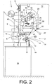
- FIG. 2 is a side view of a job of a semi-automatic open-end rotor spinning machine 1 according to the invention shown.
- the individual work stations 2 each have a spinning device 3 and a winding device 33.
- a sliver 34 presented in sliver cans 28 is spun in each case into a yarn 30, which is wound on the winding device 33 to form a cross-wound bobbin 22.
- the winding devices 33 have, for this purpose, as known per se, a creel 21 for rotatably supporting the sleeve of a cheese 22, a bobbin drive roller 23, a Fadenchangier observed 26 and a device 7 for lifting the cross-wound bobbin 22 from the bobbin drive roller 23.
- the device 7 is designed for example as a thrust piston, which is connected via a pneumatic line 24, in which a solenoid valve 17 is turned on, to a (not shown) overpressure source.
- the drive of the bobbin drive roller 23 takes place as a group drive. This means that there is provided a machine-length drive shaft on which the individual coil drive rollers 23 are fixed.
- the spinning device 3 has a spinning rotor 4, an opening roller 12 and a sliver feed cylinder 14.
- the spinning rotor 4 for example, is mounted in a support disk bearing 5 and is driven by a machine-tangential belt 6.
- a sensor device 8 can also be provided, which is then connected via a signal line 40 to the workstation control device 9 of the workstation 2.
- the opening roller 12 is preferably also acted upon by a machine-tangential belt 13, while the sliver feed cylinder 14 is driven by a motor 15 single motor.
- the drive of the sliver feed cylinder 14, for example a stepper motor 15, is likewise connected to the workstation control devices 9 via a control line 16.
- the work stations 2 furthermore each have a machine-pull-driven yarn draw-off device 18 which is connected via a control line 20 to the workstation control device 9 and, viewed in the direction of yarn travel, behind the yarn withdrawal device 18, yarn storage device 37 is connected.
- the thread storage device 37 is preferably formed as a pneumatically actuable storage nozzle, which is connected via a pneumatic line 38 to a (not shown) vacuum source.
- the workstation control device 9 which controls, among other things, the drive 15 of the sliver feed cylinder 14, also connected via a signal line 29 to a switching element 27, which can be actuated, if necessary, for example, to start a piecing process by a service unit 10, the performs auxiliary work necessary in connection with a piecing process.
- the corresponding service unit 10 is supported via a chassis 11 and a support wheel 25 movable on machine-length rails 31 and 32 and can be positioned, if necessary, at that workstation 2 at which a piecing is to be performed.
- Yarn batch 3 is another customer order with different production settings.
Landscapes
- Engineering & Computer Science (AREA)
- Mechanical Engineering (AREA)
- Textile Engineering (AREA)
- Spinning Or Twisting Of Yarns (AREA)
Claims (5)
- Machine à filer à rotor à bout libre semi-automatique (1) avec un dispositif de commande centrale subordonné (41) et des postes de travail (2) disposant chacun d'un dispositif de filage (3) pour la fabrication d'un fil (30), d'un nettoyeur de fil pour la vérification de la qualité du fil créé (30), d'un dispositif de retrait du fil (18), d'un dispositif de bobinage (33) pour la fabrication d'une bobine croisée (22) maintenue en rotation dans un cadre porte-bobine (21) ainsi que d'un dispositif de commande des poste de travail (9),
sachant que les dispositifs de commande des poste de travail sont reliés, via un bus, avec le dispositif de commande centrale subordonné,
sachant que les dispositifs de filage (3) présentent, dans leur logement de filage, des rotors de filage (4) tournant à vitesse de rotation élevée, ainsi que des dispositifs d'alimentation en bande de fibres et des cylindres couverts (12),
sachant que les rotors de filage (4), les cylindres couverts (12) ainsi que de cylindres d'entraînement de bobine (23) pour entraîner la bobine croisée (33) et le guide-fil pour poser le fil (30) sur la bobine croisée (33) des dispositifs de bobinage (33) sont équipés d'entraînements de la longueur de la machine et sachant que les cylindres d'insertion de la bande de fibres (14) des dispositifs d'alimentation en bande de fibres sont entraînés par un seul moteur pour le transport de la bande de fibres vers le cylindre couvert (12),
sachant que le dispositif de commande central (41) ou les dispositifs de commande des poste de travail (9) de groupes de poste de travail (2) à sélectionner en fonction de leurs dimensions sont conçus de manière à piloter les groupes de postes de travail de manière à ce que ceux-ci soient différents en au moins une de leurs fonctions réglage du nettoyeur, alimentation en bande de fibres, diamètre de bobine, finesse du fil et réglage de l'effet, caractérisé en ce que les dimensions des groupes, ou plus exactement, le nombre de postes de travail produisant la même partie du fil soit pilotable de manière variable et dépendante du besoin. - Machine à filer à rotor à bout libre semi-automatique (1) selon la revendication 1, caractérisée en ce que au moins 2 groupes sont configurés pour chaque côté de la machine.
- Machine à filer à rotor à bout libre semi-automatique (1) selon la revendication 1, caractérisée en ce que au moins un poste de travail (2) serve de poste de travail ou groupe pilote et soit conçu de manière à pouvoir créer une bobine maître et pouvoir retenir, dans un dispositif de commande et d'évaluation du poste de travail pilote, les paramètres de production de cette bobine maître à l'aide de valeurs de commande et/ou de courbes de commande.
- Machine à filer à rotor à bout libre semi-automatique (1) selon la revendication 1, caractérisée en ce que la saisie et/ou l'affectation des données de commande pour les dispositifs de commande des poste de travail (9) des groupes correspondants soit réalisée via le dispositif de commande central subordonné.
- Machine à filer à rotor à bout libre semi-automatique (1) selon la revendication 1, caractérisée en ce que les dispositifs de commande des postes de travail (9) sont configurés pour la saisie des données de commande.
Applications Claiming Priority (1)
| Application Number | Priority Date | Filing Date | Title |
|---|---|---|---|
| DE102014008814.6A DE102014008814A1 (de) | 2014-06-11 | 2014-06-11 | Semiautomatische Offenend-Rotorspinnmaschine |
Related Parent Applications (1)
| Application Number | Title | Priority Date | Filing Date |
|---|---|---|---|
| DE102014008814 Previously-Filed-Application | 2014-06-11 |
Publications (3)
| Publication Number | Publication Date |
|---|---|
| EP2966201A2 EP2966201A2 (fr) | 2016-01-13 |
| EP2966201A3 EP2966201A3 (fr) | 2016-04-27 |
| EP2966201B1 true EP2966201B1 (fr) | 2019-07-31 |
Family
ID=53298074
Family Applications (1)
| Application Number | Title | Priority Date | Filing Date |
|---|---|---|---|
| EP15001373.8A Active EP2966201B1 (fr) | 2014-06-11 | 2015-05-07 | Machine de filage à bout libre semi-automatique |
Country Status (3)
| Country | Link |
|---|---|
| EP (1) | EP2966201B1 (fr) |
| CN (1) | CN105177774B (fr) |
| DE (1) | DE102014008814A1 (fr) |
Families Citing this family (10)
| Publication number | Priority date | Publication date | Assignee | Title |
|---|---|---|---|---|
| DE102015012214A1 (de) | 2015-09-17 | 2017-03-23 | Saurer Germany Gmbh & Co. Kg | Verfahren zum Anpassen einer eine Garnpartieherstellung betreffenden werksseitigen Auslegung einer Offenend-Rotorspinnmaschine |
| WO2019155413A1 (fr) * | 2018-02-10 | 2019-08-15 | Dr. MGR Educational & Research Institute University | Métier à filer alimenté par ruban multibroche avec modules de boîte de filage pour le filage de fibres grossières et longues telles que des fibres de coco et de banane |
| DE102018112802A1 (de) | 2018-05-29 | 2019-12-05 | Maschinenfabrik Rieter Ag | Verfahren zum Betreiben einer Textilmaschine sowie Textilmaschine |
| DE102018131767A1 (de) * | 2018-12-11 | 2020-06-18 | Saurer Spinning Solutions Gmbh & Co. Kg | Kreuzspulen herstellende Textilmaschine |
| DE102019110295A1 (de) * | 2019-04-18 | 2020-10-22 | Saurer Spinning Solutions Gmbh & Co. Kg | Kreuzspulen herstellende Textilmaschine |
| DE102019116646A1 (de) * | 2019-06-19 | 2020-12-24 | Maschinenfabrik Rieter Ag | Verfahren zum Betreiben einer teil- oder vollautomatischen, kreuzspulenherstellenden Spinnmaschine |
| DE102020106124A1 (de) | 2020-03-06 | 2021-09-09 | Maschinenfabrik Rieter Ag | Verfahren zum Betreiben einer Spinnmaschine sowie Spinnmaschine |
| EP3919659B1 (fr) * | 2020-06-03 | 2023-02-15 | Saurer Spinning Solutions GmbH & Co. KG | Procédé de filage d'un métier à filer à rotor à bout libre et métier à filer à rotor à bout libre |
| CN113668102B (zh) * | 2020-12-30 | 2022-08-23 | 苏州多道自动化科技有限公司 | 纺纱自动输送机器人 |
| LU504425B1 (de) * | 2023-06-06 | 2024-12-06 | Saurer Spinning Solutions Gmbh & Co Kg | Verfahren zum Betreiben einer Textilmaschine |
Citations (1)
| Publication number | Priority date | Publication date | Assignee | Title |
|---|---|---|---|---|
| US7392648B2 (en) * | 2003-10-16 | 2008-07-01 | Oerlikon Textile Gmbh & Co. Kg | Rotor Spinning machine |
Family Cites Families (8)
| Publication number | Priority date | Publication date | Assignee | Title |
|---|---|---|---|---|
| DE4309947A1 (de) | 1993-03-26 | 1994-09-29 | Schlafhorst & Co W | Spinnstelle an einer Rotorspinnmaschine |
| DE19836065B4 (de) | 1998-08-10 | 2012-08-23 | Oerlikon Textile Gmbh & Co. Kg | Filterkammer für eine Textilmaschine |
| DE10139075A1 (de) | 2001-08-09 | 2003-02-20 | Schlafhorst & Co W | Offenend-Rotorspinnmaschine |
| CN2499412Y (zh) * | 2001-08-25 | 2002-07-10 | 浙江日发纺织机械有限公司 | 转杯纺纱机的半自动接头装置 |
| DE10153457B4 (de) * | 2001-10-30 | 2015-07-16 | Rieter Ingolstadt Gmbh | Textilmaschine mit einer Vielzahl von Bearbeitungsstellen und Kommunikationsverfahren hierfür |
| DE102007018536B4 (de) * | 2007-04-19 | 2018-05-30 | Saurer Germany Gmbh & Co. Kg | Offenend-Spinnmaschine |
| DE102007032237A1 (de) * | 2007-07-11 | 2009-01-15 | Rieter Ingolstadt Gmbh | Textilmaschine |
| DE102007056561A1 (de) * | 2007-08-25 | 2009-02-26 | Oerlikon Textile Gmbh & Co. Kg | Kreuzspulen herstellende Textilmaschine |
-
2014
- 2014-06-11 DE DE102014008814.6A patent/DE102014008814A1/de not_active Withdrawn
-
2015
- 2015-05-07 EP EP15001373.8A patent/EP2966201B1/fr active Active
- 2015-06-10 CN CN201510316296.2A patent/CN105177774B/zh active Active
Patent Citations (1)
| Publication number | Priority date | Publication date | Assignee | Title |
|---|---|---|---|---|
| US7392648B2 (en) * | 2003-10-16 | 2008-07-01 | Oerlikon Textile Gmbh & Co. Kg | Rotor Spinning machine |
Also Published As
| Publication number | Publication date |
|---|---|
| CN105177774B (zh) | 2018-04-10 |
| EP2966201A2 (fr) | 2016-01-13 |
| CN105177774A (zh) | 2015-12-23 |
| EP2966201A3 (fr) | 2016-04-27 |
| DE102014008814A1 (de) | 2015-12-17 |
Similar Documents
| Publication | Publication Date | Title |
|---|---|---|
| EP2966201B1 (fr) | Machine de filage à bout libre semi-automatique | |
| EP2955143B1 (fr) | Machine textile semi-automatique fabriquant des bobines | |
| EP2016212B1 (fr) | Machine à filer, étirer et texturer | |
| EP3100971B1 (fr) | Procede de fonctionnement d'une machine textile comprenant des organes de manutention propres a chaque poste de travail pour le re-attachement d'un fil et machine textile comprenant des organes de manutention | |
| EP3031761B1 (fr) | Machine textile multi-position | |
| EP2762617B1 (fr) | Procédé d'optimisation de changement de lot sur un métier à filer à fibres libérées | |
| DE102007048720B4 (de) | Verfahren und Vorrichtung zum Betreiben einer Offenend-Rotorspinnmaschine | |
| EP3237658B1 (fr) | Métier à filer à rotor comportant une pluralité d'emplacements de travail et un dispositif d'aspiration | |
| DE102005036485A1 (de) | Offenend-Rotorspinnmaschine | |
| DE102007056561A1 (de) | Kreuzspulen herstellende Textilmaschine | |
| WO2007147483A1 (fr) | Métier à filer | |
| DE102007018536B4 (de) | Offenend-Spinnmaschine | |
| EP3144418B1 (fr) | Procede d'adaptation d'une conception usine concernant une fabrication de lot de fil d'un metier a tisser a rotor a extremite ouverte | |
| DE102007053467A1 (de) | Verfahren und Vorrichtung zum Betreiben einer Offenend-Rotorspinnmaschine | |
| DE102013008107A1 (de) | Verfahren zum Betreiben einer Offenend-Rotorspinnmaschine | |
| EP3935208A1 (fr) | Procédé de fabrication de fil au moyen d'un continu à filer à anneaux et continu à filer à anneaux | |
| EP2915910B1 (fr) | Procédé et dispositif de fonctionnement d'un métier à filer à rotor | |
| DE68925017T2 (de) | Automatisches Ansetzen eines Faserbandes in einer Textilmaschine. | |
| EP3720996A1 (fr) | Procédé pour faire fonctionner une bobineuse pour bobiner les canettes d'une machine à filer à anneaux | |
| EP3617108B1 (fr) | Machine textile et procédé de commande d'une machine textile | |
| EP2813605A1 (fr) | Procédé de fonctionnement d'un poste de travail d'un métier à filer à rotor à bout libre et poste de travail associé | |
| DE102012007987A1 (de) | Verfahren und Vorrichtung zum kontinuierlichen Abziehen und Aufspulen mehrerer Fäden | |
| EP1422323B1 (fr) | Métiers à filer à vortex d'air modulaire | |
| EP3967797B1 (fr) | Machine textile, ainsi que procédé de fonctionnement d'une telle machine textile | |
| CH672326A5 (fr) |
Legal Events
| Date | Code | Title | Description |
|---|---|---|---|
| PUAI | Public reference made under article 153(3) epc to a published international application that has entered the european phase |
Free format text: ORIGINAL CODE: 0009012 |
|
| AK | Designated contracting states |
Kind code of ref document: A2 Designated state(s): AL AT BE BG CH CY CZ DE DK EE ES FI FR GB GR HR HU IE IS IT LI LT LU LV MC MK MT NL NO PL PT RO RS SE SI SK SM TR |
|
| AX | Request for extension of the european patent |
Extension state: BA ME |
|
| PUAL | Search report despatched |
Free format text: ORIGINAL CODE: 0009013 |
|
| AK | Designated contracting states |
Kind code of ref document: A3 Designated state(s): AL AT BE BG CH CY CZ DE DK EE ES FI FR GB GR HR HU IE IS IT LI LT LU LV MC MK MT NL NO PL PT RO RS SE SI SK SM TR |
|
| AX | Request for extension of the european patent |
Extension state: BA ME |
|
| RIC1 | Information provided on ipc code assigned before grant |
Ipc: D01H 4/44 20060101AFI20160322BHEP |
|
| STAA | Information on the status of an ep patent application or granted ep patent |
Free format text: STATUS: REQUEST FOR EXAMINATION WAS MADE |
|
| STAA | Information on the status of an ep patent application or granted ep patent |
Free format text: STATUS: EXAMINATION IS IN PROGRESS |
|
| 17P | Request for examination filed |
Effective date: 20161027 |
|
| RBV | Designated contracting states (corrected) |
Designated state(s): AL AT BE BG CH CY CZ DE DK EE ES FI FR GB GR HR HU IE IS IT LI LT LU LV MC MK MT NL NO PL PT RO RS SE SI SK SM TR |
|
| 17Q | First examination report despatched |
Effective date: 20161201 |
|
| RAP1 | Party data changed (applicant data changed or rights of an application transferred) |
Owner name: SAURER SPINNING SOLUTIONS GMBH & CO. KG |
|
| GRAP | Despatch of communication of intention to grant a patent |
Free format text: ORIGINAL CODE: EPIDOSNIGR1 |
|
| STAA | Information on the status of an ep patent application or granted ep patent |
Free format text: STATUS: GRANT OF PATENT IS INTENDED |
|
| GRAS | Grant fee paid |
Free format text: ORIGINAL CODE: EPIDOSNIGR3 |
|
| INTG | Intention to grant announced |
Effective date: 20190527 |
|
| GRAA | (expected) grant |
Free format text: ORIGINAL CODE: 0009210 |
|
| STAA | Information on the status of an ep patent application or granted ep patent |
Free format text: STATUS: THE PATENT HAS BEEN GRANTED |
|
| AK | Designated contracting states |
Kind code of ref document: B1 Designated state(s): AL AT BE BG CH CY CZ DE DK EE ES FI FR GB GR HR HU IE IS IT LI LT LU LV MC MK MT NL NO PL PT RO RS SE SI SK SM TR |
|
| REG | Reference to a national code |
Ref country code: CH Ref legal event code: EP Ref country code: GB Ref legal event code: FG4D Free format text: NOT ENGLISH |
|
| REG | Reference to a national code |
Ref country code: DE Ref legal event code: R096 Ref document number: 502015009786 Country of ref document: DE |
|
| REG | Reference to a national code |
Ref country code: AT Ref legal event code: REF Ref document number: 1160991 Country of ref document: AT Kind code of ref document: T Effective date: 20190815 |
|
| REG | Reference to a national code |
Ref country code: IE Ref legal event code: FG4D Free format text: LANGUAGE OF EP DOCUMENT: GERMAN |
|
| REG | Reference to a national code |
Ref country code: NL Ref legal event code: MP Effective date: 20190731 |
|
| REG | Reference to a national code |
Ref country code: LT Ref legal event code: MG4D |
|
| PG25 | Lapsed in a contracting state [announced via postgrant information from national office to epo] |
Ref country code: PT Free format text: LAPSE BECAUSE OF FAILURE TO SUBMIT A TRANSLATION OF THE DESCRIPTION OR TO PAY THE FEE WITHIN THE PRESCRIBED TIME-LIMIT Effective date: 20191202 Ref country code: BG Free format text: LAPSE BECAUSE OF FAILURE TO SUBMIT A TRANSLATION OF THE DESCRIPTION OR TO PAY THE FEE WITHIN THE PRESCRIBED TIME-LIMIT Effective date: 20191031 Ref country code: HR Free format text: LAPSE BECAUSE OF FAILURE TO SUBMIT A TRANSLATION OF THE DESCRIPTION OR TO PAY THE FEE WITHIN THE PRESCRIBED TIME-LIMIT Effective date: 20190731 Ref country code: NL Free format text: LAPSE BECAUSE OF FAILURE TO SUBMIT A TRANSLATION OF THE DESCRIPTION OR TO PAY THE FEE WITHIN THE PRESCRIBED TIME-LIMIT Effective date: 20190731 Ref country code: LT Free format text: LAPSE BECAUSE OF FAILURE TO SUBMIT A TRANSLATION OF THE DESCRIPTION OR TO PAY THE FEE WITHIN THE PRESCRIBED TIME-LIMIT Effective date: 20190731 Ref country code: NO Free format text: LAPSE BECAUSE OF FAILURE TO SUBMIT A TRANSLATION OF THE DESCRIPTION OR TO PAY THE FEE WITHIN THE PRESCRIBED TIME-LIMIT Effective date: 20191031 Ref country code: FI Free format text: LAPSE BECAUSE OF FAILURE TO SUBMIT A TRANSLATION OF THE DESCRIPTION OR TO PAY THE FEE WITHIN THE PRESCRIBED TIME-LIMIT Effective date: 20190731 Ref country code: SE Free format text: LAPSE BECAUSE OF FAILURE TO SUBMIT A TRANSLATION OF THE DESCRIPTION OR TO PAY THE FEE WITHIN THE PRESCRIBED TIME-LIMIT Effective date: 20190731 |
|
| PG25 | Lapsed in a contracting state [announced via postgrant information from national office to epo] |
Ref country code: IS Free format text: LAPSE BECAUSE OF FAILURE TO SUBMIT A TRANSLATION OF THE DESCRIPTION OR TO PAY THE FEE WITHIN THE PRESCRIBED TIME-LIMIT Effective date: 20191130 Ref country code: RS Free format text: LAPSE BECAUSE OF FAILURE TO SUBMIT A TRANSLATION OF THE DESCRIPTION OR TO PAY THE FEE WITHIN THE PRESCRIBED TIME-LIMIT Effective date: 20190731 Ref country code: LV Free format text: LAPSE BECAUSE OF FAILURE TO SUBMIT A TRANSLATION OF THE DESCRIPTION OR TO PAY THE FEE WITHIN THE PRESCRIBED TIME-LIMIT Effective date: 20190731 Ref country code: GR Free format text: LAPSE BECAUSE OF FAILURE TO SUBMIT A TRANSLATION OF THE DESCRIPTION OR TO PAY THE FEE WITHIN THE PRESCRIBED TIME-LIMIT Effective date: 20191101 Ref country code: AL Free format text: LAPSE BECAUSE OF FAILURE TO SUBMIT A TRANSLATION OF THE DESCRIPTION OR TO PAY THE FEE WITHIN THE PRESCRIBED TIME-LIMIT Effective date: 20190731 Ref country code: ES Free format text: LAPSE BECAUSE OF FAILURE TO SUBMIT A TRANSLATION OF THE DESCRIPTION OR TO PAY THE FEE WITHIN THE PRESCRIBED TIME-LIMIT Effective date: 20190731 |
|
| PG25 | Lapsed in a contracting state [announced via postgrant information from national office to epo] |
Ref country code: RO Free format text: LAPSE BECAUSE OF FAILURE TO SUBMIT A TRANSLATION OF THE DESCRIPTION OR TO PAY THE FEE WITHIN THE PRESCRIBED TIME-LIMIT Effective date: 20190731 Ref country code: EE Free format text: LAPSE BECAUSE OF FAILURE TO SUBMIT A TRANSLATION OF THE DESCRIPTION OR TO PAY THE FEE WITHIN THE PRESCRIBED TIME-LIMIT Effective date: 20190731 Ref country code: DK Free format text: LAPSE BECAUSE OF FAILURE TO SUBMIT A TRANSLATION OF THE DESCRIPTION OR TO PAY THE FEE WITHIN THE PRESCRIBED TIME-LIMIT Effective date: 20190731 Ref country code: PL Free format text: LAPSE BECAUSE OF FAILURE TO SUBMIT A TRANSLATION OF THE DESCRIPTION OR TO PAY THE FEE WITHIN THE PRESCRIBED TIME-LIMIT Effective date: 20190731 |
|
| PG25 | Lapsed in a contracting state [announced via postgrant information from national office to epo] |
Ref country code: SK Free format text: LAPSE BECAUSE OF FAILURE TO SUBMIT A TRANSLATION OF THE DESCRIPTION OR TO PAY THE FEE WITHIN THE PRESCRIBED TIME-LIMIT Effective date: 20190731 Ref country code: IS Free format text: LAPSE BECAUSE OF FAILURE TO SUBMIT A TRANSLATION OF THE DESCRIPTION OR TO PAY THE FEE WITHIN THE PRESCRIBED TIME-LIMIT Effective date: 20200224 Ref country code: SM Free format text: LAPSE BECAUSE OF FAILURE TO SUBMIT A TRANSLATION OF THE DESCRIPTION OR TO PAY THE FEE WITHIN THE PRESCRIBED TIME-LIMIT Effective date: 20190731 |
|
| REG | Reference to a national code |
Ref country code: DE Ref legal event code: R097 Ref document number: 502015009786 Country of ref document: DE |
|
| PLBE | No opposition filed within time limit |
Free format text: ORIGINAL CODE: 0009261 |
|
| STAA | Information on the status of an ep patent application or granted ep patent |
Free format text: STATUS: NO OPPOSITION FILED WITHIN TIME LIMIT |
|
| PG2D | Information on lapse in contracting state deleted |
Ref country code: IS |
|
| PG25 | Lapsed in a contracting state [announced via postgrant information from national office to epo] |
Ref country code: IS Free format text: LAPSE BECAUSE OF FAILURE TO SUBMIT A TRANSLATION OF THE DESCRIPTION OR TO PAY THE FEE WITHIN THE PRESCRIBED TIME-LIMIT Effective date: 20191030 |
|
| 26N | No opposition filed |
Effective date: 20200603 |
|
| PG25 | Lapsed in a contracting state [announced via postgrant information from national office to epo] |
Ref country code: SI Free format text: LAPSE BECAUSE OF FAILURE TO SUBMIT A TRANSLATION OF THE DESCRIPTION OR TO PAY THE FEE WITHIN THE PRESCRIBED TIME-LIMIT Effective date: 20190731 |
|
| PG25 | Lapsed in a contracting state [announced via postgrant information from national office to epo] |
Ref country code: MC Free format text: LAPSE BECAUSE OF FAILURE TO SUBMIT A TRANSLATION OF THE DESCRIPTION OR TO PAY THE FEE WITHIN THE PRESCRIBED TIME-LIMIT Effective date: 20190731 |
|
| REG | Reference to a national code |
Ref country code: BE Ref legal event code: MM Effective date: 20200531 |
|
| GBPC | Gb: european patent ceased through non-payment of renewal fee |
Effective date: 20200507 |
|
| PG25 | Lapsed in a contracting state [announced via postgrant information from national office to epo] |
Ref country code: LU Free format text: LAPSE BECAUSE OF NON-PAYMENT OF DUE FEES Effective date: 20200507 |
|
| PG25 | Lapsed in a contracting state [announced via postgrant information from national office to epo] |
Ref country code: GB Free format text: LAPSE BECAUSE OF NON-PAYMENT OF DUE FEES Effective date: 20200507 Ref country code: IE Free format text: LAPSE BECAUSE OF NON-PAYMENT OF DUE FEES Effective date: 20200507 Ref country code: FR Free format text: LAPSE BECAUSE OF NON-PAYMENT OF DUE FEES Effective date: 20200531 |
|
| PG25 | Lapsed in a contracting state [announced via postgrant information from national office to epo] |
Ref country code: BE Free format text: LAPSE BECAUSE OF NON-PAYMENT OF DUE FEES Effective date: 20200531 |
|
| REG | Reference to a national code |
Ref country code: AT Ref legal event code: MM01 Ref document number: 1160991 Country of ref document: AT Kind code of ref document: T Effective date: 20200507 |
|
| PG25 | Lapsed in a contracting state [announced via postgrant information from national office to epo] |
Ref country code: AT Free format text: LAPSE BECAUSE OF NON-PAYMENT OF DUE FEES Effective date: 20200507 |
|
| PG25 | Lapsed in a contracting state [announced via postgrant information from national office to epo] |
Ref country code: MT Free format text: LAPSE BECAUSE OF FAILURE TO SUBMIT A TRANSLATION OF THE DESCRIPTION OR TO PAY THE FEE WITHIN THE PRESCRIBED TIME-LIMIT Effective date: 20190731 Ref country code: CY Free format text: LAPSE BECAUSE OF FAILURE TO SUBMIT A TRANSLATION OF THE DESCRIPTION OR TO PAY THE FEE WITHIN THE PRESCRIBED TIME-LIMIT Effective date: 20190731 |
|
| PG25 | Lapsed in a contracting state [announced via postgrant information from national office to epo] |
Ref country code: MK Free format text: LAPSE BECAUSE OF FAILURE TO SUBMIT A TRANSLATION OF THE DESCRIPTION OR TO PAY THE FEE WITHIN THE PRESCRIBED TIME-LIMIT Effective date: 20190731 |
|
| PGFP | Annual fee paid to national office [announced via postgrant information from national office to epo] |
Ref country code: DE Payment date: 20250519 Year of fee payment: 11 |
|
| PGFP | Annual fee paid to national office [announced via postgrant information from national office to epo] |
Ref country code: IT Payment date: 20250530 Year of fee payment: 11 |
|
| PGFP | Annual fee paid to national office [announced via postgrant information from national office to epo] |
Ref country code: CH Payment date: 20250601 Year of fee payment: 11 |
|
| PGFP | Annual fee paid to national office [announced via postgrant information from national office to epo] |
Ref country code: TR Payment date: 20250430 Year of fee payment: 11 |
|
| PGFP | Annual fee paid to national office [announced via postgrant information from national office to epo] |
Ref country code: CZ Payment date: 20250424 Year of fee payment: 11 |