EP2966342A1 - Beleuchtungsmodul für kfz-projektionssheinwerfer mit positioniermittel zwischen kühlkörper und reflektor/linse - Google Patents
Beleuchtungsmodul für kfz-projektionssheinwerfer mit positioniermittel zwischen kühlkörper und reflektor/linse Download PDFInfo
- Publication number
- EP2966342A1 EP2966342A1 EP15173917.4A EP15173917A EP2966342A1 EP 2966342 A1 EP2966342 A1 EP 2966342A1 EP 15173917 A EP15173917 A EP 15173917A EP 2966342 A1 EP2966342 A1 EP 2966342A1
- Authority
- EP
- European Patent Office
- Prior art keywords
- heat sink
- support
- lens
- module
- light module
- Prior art date
- Legal status (The legal status is an assumption and is not a legal conclusion. Google has not performed a legal analysis and makes no representation as to the accuracy of the status listed.)
- Granted
Links
Images


Classifications
-
- F—MECHANICAL ENGINEERING; LIGHTING; HEATING; WEAPONS; BLASTING
- F21—LIGHTING
- F21S—NON-PORTABLE LIGHTING DEVICES; SYSTEMS THEREOF; VEHICLE LIGHTING DEVICES SPECIALLY ADAPTED FOR VEHICLE EXTERIORS
- F21S45/00—Arrangements within vehicle lighting devices specially adapted for vehicle exteriors, for purposes other than emission or distribution of light
- F21S45/40—Cooling of lighting devices
- F21S45/47—Passive cooling, e.g. using fins, thermal conductive elements or openings
-
- F—MECHANICAL ENGINEERING; LIGHTING; HEATING; WEAPONS; BLASTING
- F21—LIGHTING
- F21S—NON-PORTABLE LIGHTING DEVICES; SYSTEMS THEREOF; VEHICLE LIGHTING DEVICES SPECIALLY ADAPTED FOR VEHICLE EXTERIORS
- F21S41/00—Illuminating devices specially adapted for vehicle exteriors, e.g. headlamps
- F21S41/10—Illuminating devices specially adapted for vehicle exteriors, e.g. headlamps characterised by the light source
- F21S41/19—Attachment of light sources or lamp holders
- F21S41/192—Details of lamp holders, terminals or connectors
-
- F—MECHANICAL ENGINEERING; LIGHTING; HEATING; WEAPONS; BLASTING
- F21—LIGHTING
- F21S—NON-PORTABLE LIGHTING DEVICES; SYSTEMS THEREOF; VEHICLE LIGHTING DEVICES SPECIALLY ADAPTED FOR VEHICLE EXTERIORS
- F21S41/00—Illuminating devices specially adapted for vehicle exteriors, e.g. headlamps
- F21S41/20—Illuminating devices specially adapted for vehicle exteriors, e.g. headlamps characterised by refractors, transparent cover plates, light guides or filters
- F21S41/29—Attachment thereof
- F21S41/295—Attachment thereof specially adapted to projection lenses
-
- F—MECHANICAL ENGINEERING; LIGHTING; HEATING; WEAPONS; BLASTING
- F21—LIGHTING
- F21S—NON-PORTABLE LIGHTING DEVICES; SYSTEMS THEREOF; VEHICLE LIGHTING DEVICES SPECIALLY ADAPTED FOR VEHICLE EXTERIORS
- F21S41/00—Illuminating devices specially adapted for vehicle exteriors, e.g. headlamps
- F21S41/30—Illuminating devices specially adapted for vehicle exteriors, e.g. headlamps characterised by reflectors
- F21S41/39—Attachment thereof
-
- F—MECHANICAL ENGINEERING; LIGHTING; HEATING; WEAPONS; BLASTING
- F21—LIGHTING
- F21S—NON-PORTABLE LIGHTING DEVICES; SYSTEMS THEREOF; VEHICLE LIGHTING DEVICES SPECIALLY ADAPTED FOR VEHICLE EXTERIORS
- F21S45/00—Arrangements within vehicle lighting devices specially adapted for vehicle exteriors, for purposes other than emission or distribution of light
- F21S45/40—Cooling of lighting devices
- F21S45/49—Attachment of the cooling means
-
- F—MECHANICAL ENGINEERING; LIGHTING; HEATING; WEAPONS; BLASTING
- F21—LIGHTING
- F21S—NON-PORTABLE LIGHTING DEVICES; SYSTEMS THEREOF; VEHICLE LIGHTING DEVICES SPECIALLY ADAPTED FOR VEHICLE EXTERIORS
- F21S41/00—Illuminating devices specially adapted for vehicle exteriors, e.g. headlamps
- F21S41/30—Illuminating devices specially adapted for vehicle exteriors, e.g. headlamps characterised by reflectors
- F21S41/32—Optical layout thereof
- F21S41/321—Optical layout thereof the reflector being a surface of revolution or a planar surface, e.g. truncated
Definitions
- the invention relates to the field of lighting, more particularly to automotive lighting.
- the invention relates to a projector lighting module for a motor vehicle.
- the published patent document EP 2 428 725 A2 discloses a car projector lighting module.
- the lighting module in question comprises a light-emitting diode-type light source (LED) mounted on a plate disposed on a cooling radiator of said diode.
- the module also comprises a first reflective surface in the form of a half-shell and able to reflect the rays emitted by the light source towards a second reflective surface, called a bending surface, with a cutting edge of the illumination beam.
- the lighting module also includes a lens disposed at the front of the second reflective surface. The rays reflected by the first reflective surface and which pass in front of the cutting edge of the pious meet the lens and are deflected by it.
- rays meeting the second reflecting surface instead of meeting the lens at its lower part with a lower incidence angle than the previous rays, are reflected towards the upper part of the lens with a substantially identical angle of incidence. These rays are then deflected by the lens towards the bottom of the beam instead of being deflected upwards, thus achieving a typical cutoff of a lighting beam of the "code" type or even dipped beam.
- a main part serves as support for the lens, the reflective surface in the form of a half-shell and the folder. This piece is then attached to the radiator. The latter directly supports the plate with the light source.
- the longitudinal positioning between the main part and the radiator is effected by means of eyelets on the main part cooperating by engagement with drums on the radiator.
- the main part comprises abutment surfaces cooperating directly with the radiator for vertical positioning.
- This teaching is interesting in that the main piece ensures a precise relative positioning between the lens, the reflective surface, the folder and the radiator. Indeed, the lens is fully supported by the main piece. In the case of bulky and heavy lenses, this can pose some difficulties in terms of stability of the lens especially in the presence of vibrations. In addition, the main piece is a complicated piece that may also have some manufacturing tolerances potentially affecting the accuracy of the assembly.
- the object of the invention is to overcome at least one of the drawbacks of the prior art, more particularly of the aforementioned prior art. More particularly, the invention aims to provide a lighting module whose implementation is simplified while maintaining a high level of accuracy between the lens and the rest of the module, such as the reflecting surface and the source or sources bright.
- the subject of the invention is a light module, in particular for lighting and / or signaling, for a motor vehicle, comprising: at least one light source; a heat sink adapted to dissipate the heat produced by said source or sources; a reflective surface capable of reflecting the rays of the light source or sources; a lens adapted to deflect the rays from the reflecting surface to form a light beam along an optical axis of the module; a support for the lens and the reflective surface, said support being mounted on the heat sink; remarkable in that the heat sink and / or the support comprises at least one, preferably at least two bosses in contact with each other of the dissipator and the support so as to maintain a predetermined distance between the dissipator and the support.
- the boss or bosses are directed vertically.
- the boss or bosses are located, in the direction of the optical axis, between the reflecting surface and the lens.
- the lens comprises at least one, preferably at least two lower fastening tabs extending vertically through the support.
- the support comprises a notch, the lower fastening tab or tabs extending through this notch.
- the or each of the fixing lugs cooperates by engagement with the heat sink, said engagement preferably having a vertical clearance of less than 0.5 mm, more preferably a vertical clearance of less than 0.1 mm, more preferably still a vertical tightening.
- the heat sink comprises a rear portion supporting the light source or sources and a front portion, the boss or bosses being on the front portion.
- the front portion of the heat sink is against the bottom portion of said dissipator.
- the heat sink has a stepped profile, the front portion forming a first step of said staircase and the rear portion forming a second step, higher, said staircase.
- the support extends along the respective upper surfaces of the front and rear portions of the heat sink, the lens being in vertical support on said support.
- the engagement between the lens and the heat sink is on the front portion of said dissipator.
- the front portion of the heat sink comprises at least one, preferably at least two tabs extending forward and cooperating by engagement with an opening in the or the lugs of the lens, respectively.
- the or each leg of the heat sink forms a stop in the direction of the optical axis for the corresponding fixing lug of the lens.
- the or each leg of the heat sink has a profile forming, in the direction of the optical axis, a projection.
- the or each of the legs of the heat sink comprises at least one rib extending in the direction of the axis. optical, so as to achieve a clamping engagement with the corresponding fixing lug of the lens.
- At least two of the bosses are arranged laterally on either side of the optical axis of the module.
- the reflecting surface and the support are a single piece.
- the reflecting surface may be formed on a cavity of the support, for example by metallization of this cavity, if necessary the reflecting surface and the support forms the same part.
- the support comprises positioning means with respect to the heat sink and in the direction of the optical axis.
- the positioning means of the support in the direction of the optical axis cooperate with a plate supporting the light source or sources, said plate being disposed on the rear portion of the heat sink.
- the light source (s) are of the electroluminescence diode type.
- the plate comprises a printed circuit, preferably with a connector, said circuit being connected to the light source or sources for their power supply.
- the means for positioning the support in the direction of the optical axis comprise at least one, preferably at least two lugs, each of the lugs protruding vertically downwards in a cavity of the heat sink, said abutment or each of said abutments cooperating by contact with the edge of an orifice in the plate.
- the heat sink is made of metal material and / or molded plastic, the or at least two of the bosses being integral with the dissipator and made by molding said dissipator.
- the invention also relates to a light device for a motor vehicle, comprising a housing and at least one light module, remarkable in that the module or at least one of the modules is in accordance with the invention.
- the measures of the invention are interesting in that they make it possible to easily and economically achieve a lighting module with a precise positioning of the lens relative to the reflecting surface and / or the light source or sources.
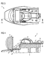
- the figure 1 is a perspective representation of a lighting module according to the invention.
- This lighting module can be mounted in a motor vehicle headlight. In this case, this module produces a cut-off lighting beam such as for a lighting function of the "code" type or even dipped beam.
- the lighting module 2 illustrated at figure 1 comprises, essentially a radiator, or heat sink, 6 on which is arranged a plate 16 provided with one or more light sources 12, preferably of the electroluminescence diode type.
- a support 4 shown in transparency and extending over the entire length of the module is disposed on the radiator 6.
- the support is in contact with a lens 8 and comprises a reflecting surface 10.
- the latter has a generally half-shell shape covering the light source 12.
- the profile of the reflecting surface 10 may be generally elliptical with two foci.
- the light source is located at the first focus and a reflective surface 14 is located substantially in the plane of the light source and with a leading edge located at the second focus.
- Reflective surface 14 is commonly referred to as a "bender" in that it reflects a portion of rays from the reflecting surface 10 to an upper portion of the lens. Indeed, in the absence of the reflective surface 14, the rays passing behind the second focus would meet the lens at a lower part with a lower incidence angle than those passing through the second focus. These rays would then be deflected by the lens so as to form the upper part of the illumination beam. The fact of returning these rays to an upper part of the lens makes it possible to reverse this effect and to form the lower part of the beam. The front edge of the folder 14 thus forms a horizontal cut of the beam.
- the reflective surface of the folder 14 forms a projection in the middle so as to form two different cutoff levels between the left and the right part of the illumination beam, in accordance with the regulations concerning vehicle lighting in effect in most countries.
- the use of a folder to form a cut-off light beam is well known to those skilled in the art.
- the lighting beam is in a main direction commonly called optical axis of the module.
- This axis also essentially corresponds to the longitudinal axis of the module.
- the plate 16 comprises at its rear part a connector 18 for its connection to the electrical harness of the projector and the vehicle.
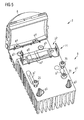
- the figure 2 illustrates the radiator 6 of the module of the figure 1 , the radiator being equipped only with the folder 14 and the plate 16. It can be observed that the radiator 6 comprises a rear portion 6 1 supporting the plate and a front portion 6 2 .
- the front portion 6 2 is at a lower level than the rear portion 6 1 .
- the profile of the radiator 6 is similar to that of a staircase, the front portion 6 2 corresponding to a first step and the rear portion 6 1 forming a second step, greater than the first.
- the folder 14 is located essentially at the front edge of the rear portion 6 1 . More specifically, the folder 14 comprises a central reflective portion 14 1 and two lateral portions 14 2 in the form of a support arm 4 ( figure 1 ). This fixation will be further detailed in relation to the figure 6 .
- the folder 14 thus has a transverse U-shaped profile where only the central portion 14 1 is optically active.
- the folder can be made from a portion of sheet metal, by shaping, folding and cutting.
- the front portion 6 2 comprises on its upper surface two bosses 6 3 . These bosses are intended to ensure exact positioning in the vertical direction of the support 4, as will be detailed in connection with the Figures 3 and 4 . These bosses can be more numerous. It could also be one or more protrusions extending transversely, in the manner of a rib.
- the front portion 6 2 also comprises, at its front edge, two lugs 6 4 for fixing the lens 8 ( figure 1 ), as will be detailed in relation to the Figures 3 and 4 .
- the rear portion 6 1 may comprise one or more pins, in this case two pins 6 3 for passing through corresponding holes of the plate 16. These pins may be generally conical.
- the plate 16 also comprises orifices 16 1 intended to receive fastening screws and oblong holes 16 2 intended to allow longitudinal positioning, that is to say in the direction of the optical axis, of the support 4 relative to at the turntable 16.
- the figure 3 is an elevation view of the module of the figure 1 .
- the figure 4 is a representation in section along the axis IV-IV of the figure 3 . It can be seen that the support 4 comprises several portions, in this case a rear portion 4 1 in contact with the plate 16 on the rear portion 6 1 of the radiator, an intermediate portion 4 2 and a front portion 4 3 disposed above the front portion 6 2 of the radiator 6 and on its bosses 6 3 .
- the lens 8 comprises two fastening tabs 8 1 extending from a lower edge to the lugs 6 4 of the radiator 6. More specifically, these lugs 8 1 extend through openings 24 in the front portion 4 3 of the support 4. These lugs 8 1 may comprise cavities, or through passages, fitting the ends of the lugs 6 4 .
- the front portion 4 3 of the support 4 is, on its underside, bearing on the bosses 3 and 6, on its upper face bears against the lens 8. The front portion 4 3 is thus vertically positioned accurately by relative to the radiator 6 as well as to the lens 8.
- the engagement between the legs 6 4 of the radiator 6 and the holes or cavities of the fastening tabs 8 1 of the lens 8 is preferably without play, more particularly with a clamping.
- the tabs 6 4 of the radiator 6 may have at their ends longitudinal ribs intended to ensure a slight tightening with the fastening tabs 8 1 of the lens.
- the material of the lens being preferably a translucent or transparent plastic material, such as for example polycarbonate, the fastening tabs 8 1 may be deformed somewhat when they are placed on the legs 6 4 , in order to avoid any play. mechanical and uncertainty as to the vertical positioning of the lens.
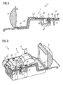
- the figure 5 illustrates the radiator 6 of the module of the figure 1 , equipped only with the lens 8 and the folder 14, the latter being represented in transparency.
- the radiator comprises ribs 6 6 in the shape of H in the longitudinal direction of the module. These ribs serve as a bearing surface for the folder 14. It is indeed important that the folder 14, more particularly its central portion 14 1 reflecting, is parallel to the upper surface of the rear portion 6 1 of the radiator 6. Indeed any misalignment of the reflective surface of the folder 14 is likely to significantly modify the photometry of the light beam of the module. It is therefore important to be able to accurately position the folder 14 not only in translation in the longitudinal direction but also vertically and in rotation about a transverse axis.
- the ribs 6 6 provide vertical and rotational positioning about a transverse axis of the folder 14. They also prevent light leakage between the underside of the central portion 14 1 and the upper face of the rear portion 6 1 of the radiator.
- the rear portion 6 1 of the radiator comprises two cavities 6 7 whose function will be detailed in relation to the Figures 8 and 9 .
- Fixing screws 20 and 22 of the plate supporting the light source and the support are visible at the figure 5 .
- the figure 6 is a cross-sectional view of the module of the figure 1 , the section being at the level of the folder 14.
- This view illustrates the mode of fixing and positioning of the folder 14. It can be observed that the central portion 14 1 of the folder is in contact with the transverse rib 6 6 of the radiator 6.
- the fastening arms 14 2 of the brake cooperate by engagement with holes in the support 4. These arms 14 2 may include for this purpose retaining tabs intended to allow the insertion of the arms 14 2 in the orifices and to prevent their exit from these orifices.
- Other fixing and / or retaining means can be envisaged.
- the ribs 6 6 illustrated in FIGS. figures 5 and 6 are preferably integral with the radiator 6.
- the latter is preferably made of metal or plastic material capable of being molded, such as for example aluminum or thermoplastics having thermal conduction properties. It is therefore interesting to make these ribs directly during the realization of the radiator.
- these ribs may deviate from that illustrated in figures 5 and 6 . Indeed, they could for example include two transverse ribs parallel and distant from each other. They could also have a U-shaped profile or in the form of a rectangle. It could also be several point bosses.
- the figure 7 is an elevation view of the module of the figure 1 . Unlike the figure 3 , the figure 7 illustrates the module provided with fixing screws 20 and 22, visible in particular at the figure 5 . As can be seen at figure 7 the cutting axis VIII-VIII passes through an oblong hole 4 5 of the support 4 as well as one of the pins 6 5 of the radiator 6. The head of the fastening screw 22 passing through this oblong hole is totally received by said hole, meaning that this screw is not supported on the support 4 but only on the plate.
- the figure 8 is a representation in section along the axis VIII-VIII of the figure 7 .
- the figure 9 is a sectional view VIII-VIII of the module of the figure 7 however, the view is in perspective and the point of view of the section opposite to that of the figure 8 .
- the support 4 comprises two lugs 4 4 , on either side of the longitudinal or optical axis of the module.
- Each of these lugs 4 4 extends from the rear portion 4 1 of the support to a cavity 6 7 , that is to say substantially vertically downwards.
- Each of the lugs 4 4 also crosses an oblong hole 16 2 formed in the plate 16 and bears in the longitudinal direction against the edge of said hole.
- the support is directed rearward, that is to say that it is the rear portion of the edge of the oblong hole 16 2 which is in contact with the lug 4 4 .
- this support could be directed forward.
- the cavities 6 7 may be sized to allow the pins 4 4 move freely when positioning the holder 4. To this end, the cavity may extend beyond the edge of 16 2 slot with which the ergot 4 4 abuts.
- the plate 16 is fixed by the screw 22 through the oblong hole 4 5 of the support.
- the plate 16 can be positioned on the radiator 6 thanks to the two pins 6 5 of said radiator which cooperate with corresponding orifices of the plate 16.
- the rear portion 4 1 of said support is deposited against the plate 16 by ensuring that the lugs 4 4 4 penetrate the oblong holes 16 2 of the plate and the cavities corresponding 6 7 of the radiator.
- 4 oblong holes 6 may be provided to cooperate with the pins on May 6 while allowing movement of the carrier 4.
- the support 4 When the rear portion 4 1 of the holder 4 is in contact with the plate 16, the support 4 can then be moved essentially in the longitudinal direction so as to bring each of the lugs 4 4 in contact with the corresponding edge of the oblong holes 16 2 of the plate.
- the fixing screws 20 bearing on the support can then be put in place and tightened in order to secure the support 4 and the plate 16 on the radiator 6.
- lugs 4 4 as stop means in the longitudinal direction acting between the support and the plate ensures exact positioning between the reflecting surface 10, supported by the support, and the light source.
- the pins and the oblong holes of the plate with which they cooperate can be designed to ensure positioning not only in the longitudinal direction but also in the transverse direction, that is to say a positioning in the plane sliding between the plate and the rear portion of the support.
- the edge of the oblong holes and / or the corresponding lug may / may be profiled (s) so as to ensure a centering of the corresponding lug.
Landscapes
- Engineering & Computer Science (AREA)
- General Engineering & Computer Science (AREA)
- Non-Portable Lighting Devices Or Systems Thereof (AREA)
- Arrangement Of Elements, Cooling, Sealing, Or The Like Of Lighting Devices (AREA)
- Physics & Mathematics (AREA)
- Microelectronics & Electronic Packaging (AREA)
- Optics & Photonics (AREA)
Applications Claiming Priority (1)
| Application Number | Priority Date | Filing Date | Title |
|---|---|---|---|
| FR1456227A FR3022974B1 (fr) | 2014-06-30 | 2014-06-30 | Module d'eclairage pour projecteur automobile avec positionnement entre reflecteur et lentille |
Publications (2)
| Publication Number | Publication Date |
|---|---|
| EP2966342A1 true EP2966342A1 (de) | 2016-01-13 |
| EP2966342B1 EP2966342B1 (de) | 2022-11-02 |
Family
ID=51519058
Family Applications (1)
| Application Number | Title | Priority Date | Filing Date |
|---|---|---|---|
| EP15173917.4A Active EP2966342B1 (de) | 2014-06-30 | 2015-06-25 | Beleuchtungsmodul eines projektionsscheinwerfers für ein kraftfahrzeug |
Country Status (5)
| Country | Link |
|---|---|
| US (1) | US10060588B2 (de) |
| EP (1) | EP2966342B1 (de) |
| CN (1) | CN105222050B (de) |
| FR (1) | FR3022974B1 (de) |
| MX (1) | MX2015008532A (de) |
Cited By (1)
| Publication number | Priority date | Publication date | Assignee | Title |
|---|---|---|---|---|
| EP3299702A1 (de) * | 2016-09-26 | 2018-03-28 | Valeo Vision | Optisches leuchtmodul eines kraftfahrzeugs |
Families Citing this family (8)
| Publication number | Priority date | Publication date | Assignee | Title |
|---|---|---|---|---|
| FR3037381B1 (fr) * | 2015-06-11 | 2021-02-19 | Valeo Vision | Dispositif de positionnement d'un support lumineux d'une diode electroluminescente sur un element support et module lumineux pour dispositif d'eclairage et/ou de signalisation comportant un tel dispositif |
| DE102017104841A1 (de) * | 2017-03-08 | 2018-09-13 | HELLA GmbH & Co. KGaA | Beleuchtungsvorrichtung für Fahrzeuge sowie Montageverfahren |
| WO2019194276A1 (ja) * | 2018-04-06 | 2019-10-10 | 株式会社小糸製作所 | 車両用灯具、空間光変調ユニットおよび灯具ユニット |
| JP7169189B2 (ja) * | 2018-12-27 | 2022-11-10 | 株式会社小糸製作所 | 灯具ユニット |
| JP7021999B2 (ja) * | 2018-04-06 | 2022-02-17 | 株式会社小糸製作所 | 車両用灯具 |
| WO2020151813A1 (en) * | 2019-01-23 | 2020-07-30 | HELLA GmbH & Co. KGaA | Illumination device for a vehicle with positioning means |
| EP3757450A1 (de) * | 2019-06-27 | 2020-12-30 | ZKW Group GmbH | Beleuchtungsvorrichtung eines kraftfahrzeugscheinwerfers |
| US10823356B1 (en) | 2019-12-20 | 2020-11-03 | Valeo Vision | Device and method of focusing a light |
Citations (8)
| Publication number | Priority date | Publication date | Assignee | Title |
|---|---|---|---|---|
| JP2008047383A (ja) * | 2006-08-14 | 2008-02-28 | Ichikoh Ind Ltd | 車両用灯具 |
| US20100246204A1 (en) * | 2009-03-31 | 2010-09-30 | Koito Manufacturing Co., Ltd. | Lamp unit |
| EP2428725A2 (de) | 2010-09-10 | 2012-03-14 | Koito Manufacturing Co., Ltd. | Fahrscheugscheinwerfer |
| EP2522898A2 (de) * | 2011-05-12 | 2012-11-14 | Koito Manufacturing Co., Ltd. | Fahrzeugleuchte |
| US20130107564A1 (en) * | 2011-07-29 | 2013-05-02 | Yasushi Yatsuda | Vehicle lighting unit |
| EP2589479A2 (de) * | 2011-11-02 | 2013-05-08 | Zizala Lichtsysteme GmbH | Verfahren zur Herstellung von Reflektoren |
| US20130120988A1 (en) * | 2010-07-20 | 2013-05-16 | Magna International, Inc. | Hybrid projector led low beam headlamp |
| EP2733412A2 (de) * | 2012-11-20 | 2014-05-21 | Koito Manufacturing Co., Ltd. | Fahrzeuglampe |
Family Cites Families (8)
| Publication number | Priority date | Publication date | Assignee | Title |
|---|---|---|---|---|
| US6819506B1 (en) * | 2003-09-30 | 2004-11-16 | Infinity Trading Co. Ltd. | Optical lens system for projecting light in a lambertion pattern from a high power led light source |
| US20080165548A1 (en) * | 2006-12-27 | 2008-07-10 | Toyoda Gosei Co., Ltd. | Vehicle lighting assembly |
| JP2008204903A (ja) * | 2007-02-22 | 2008-09-04 | Ichikoh Ind Ltd | 車両用前照灯の灯具ユニット |
| JP2010080075A (ja) * | 2008-09-24 | 2010-04-08 | Ichikoh Ind Ltd | 車両用灯具 |
| US9028097B2 (en) * | 2009-10-30 | 2015-05-12 | Cree, Inc. | LED apparatus and method for accurate lens alignment |
| US8636394B2 (en) * | 2011-12-06 | 2014-01-28 | Truck-Lite Co., Llc | Light emitting diode perimeter lamp assembly |
| TWM445667U (zh) * | 2012-09-07 | 2013-01-21 | Coplus Inc | 霧燈 |
| JP6164464B2 (ja) * | 2013-04-25 | 2017-07-19 | スタンレー電気株式会社 | 車両用灯具 |
-
2014
- 2014-06-30 FR FR1456227A patent/FR3022974B1/fr not_active Expired - Fee Related
-
2015
- 2015-06-25 EP EP15173917.4A patent/EP2966342B1/de active Active
- 2015-06-26 US US14/751,867 patent/US10060588B2/en active Active
- 2015-06-29 MX MX2015008532A patent/MX2015008532A/es unknown
- 2015-06-30 CN CN201510386332.2A patent/CN105222050B/zh active Active
Patent Citations (8)
| Publication number | Priority date | Publication date | Assignee | Title |
|---|---|---|---|---|
| JP2008047383A (ja) * | 2006-08-14 | 2008-02-28 | Ichikoh Ind Ltd | 車両用灯具 |
| US20100246204A1 (en) * | 2009-03-31 | 2010-09-30 | Koito Manufacturing Co., Ltd. | Lamp unit |
| US20130120988A1 (en) * | 2010-07-20 | 2013-05-16 | Magna International, Inc. | Hybrid projector led low beam headlamp |
| EP2428725A2 (de) | 2010-09-10 | 2012-03-14 | Koito Manufacturing Co., Ltd. | Fahrscheugscheinwerfer |
| EP2522898A2 (de) * | 2011-05-12 | 2012-11-14 | Koito Manufacturing Co., Ltd. | Fahrzeugleuchte |
| US20130107564A1 (en) * | 2011-07-29 | 2013-05-02 | Yasushi Yatsuda | Vehicle lighting unit |
| EP2589479A2 (de) * | 2011-11-02 | 2013-05-08 | Zizala Lichtsysteme GmbH | Verfahren zur Herstellung von Reflektoren |
| EP2733412A2 (de) * | 2012-11-20 | 2014-05-21 | Koito Manufacturing Co., Ltd. | Fahrzeuglampe |
Cited By (3)
| Publication number | Priority date | Publication date | Assignee | Title |
|---|---|---|---|---|
| EP3299702A1 (de) * | 2016-09-26 | 2018-03-28 | Valeo Vision | Optisches leuchtmodul eines kraftfahrzeugs |
| FR3056690A1 (fr) * | 2016-09-26 | 2018-03-30 | Valeo Vision | Module optique lumineux de vehicule automobile |
| US10378723B2 (en) | 2016-09-26 | 2019-08-13 | Valeo Vision | Motor vehicle light-emitting optical module |
Also Published As
| Publication number | Publication date |
|---|---|
| US10060588B2 (en) | 2018-08-28 |
| EP2966342B1 (de) | 2022-11-02 |
| FR3022974B1 (fr) | 2018-11-09 |
| CN105222050B (zh) | 2019-08-02 |
| MX2015008532A (es) | 2016-02-03 |
| FR3022974A1 (fr) | 2016-01-01 |
| CN105222050A (zh) | 2016-01-06 |
| US20150377439A1 (en) | 2015-12-31 |
Similar Documents
| Publication | Publication Date | Title |
|---|---|---|
| EP2966342B1 (de) | Beleuchtungsmodul eines projektionsscheinwerfers für ein kraftfahrzeug | |
| EP2966343B1 (de) | Beleuchtungsmodul für autoscheinwerfer mit positioniermittel zwischen kühlkörper und reflektor/leiterplatte | |
| EP2598793B1 (de) | Optisches modul einer beleuchtungs- und/oder signalisierungsvorrichtung eines kraftfahrzeuges | |
| EP2775197B1 (de) | Vorrichtung zur Beleuchtung und/oder Signalisierung für ein Kraftfahrzeug, die einen Lichtwellenleiter umfasst | |
| EP3822538B1 (de) | Optisches modul einer beleuchtungs- und/oder signalisierungvorrichtung eines kraftfahrzeugs | |
| EP4065882B1 (de) | Lichtmodul eines kraftfahrzeugs, das mit einem optischen element ausgestattet ist | |
| EP2921772B1 (de) | Leuchtmodul eines kraftfahrzeugs | |
| EP2574501B1 (de) | Vorrichtung zur Beleuchtung und/oder Signalisierung für ein Fahrzeug | |
| EP3489576B1 (de) | Leuchtmodul zur beleuchtung und/oder signalisierung eines kraftfahrzeugs | |
| EP2574503A1 (de) | Scheinwerfermodul eines Kraftfahrzeugs mit Bajonettverschluss, Halterung und entsprechender Scheinwerfer | |
| EP3537040B1 (de) | Leuchtmodul und leuchtvorrichtung für kraftfahrzeug, das ein solches leuchtmodul umfasst | |
| EP3884206B1 (de) | Multifunktionales lichtmodul mit zwei flachen lichtleitern | |
| EP2620325B1 (de) | Optisches Modul | |
| EP3299702B1 (de) | Optisches leuchtmodul eines kraftfahrzeugs | |
| EP3486554B1 (de) | Lichtmodul für fahrzeugscheinwerfer | |
| EP2966340B1 (de) | Beleuchtungsmodul eines scheinwerfers für ein kraftfahrzeug | |
| FR2964723A1 (fr) | Module optique de dispositif d'eclairage et / ou de signalisation d'un vehicule automobile | |
| EP2966341B1 (de) | Blende eines kfz-scheinwerfers | |
| FR2964724A1 (fr) | Module optique de dispositif d'eclairage et/ou de signalisation d'un vehicule automobile. | |
| FR3136833A1 (fr) | Module d’éclairage automobile avec écran bloqueur servant à positionner les sources lumineuses |
Legal Events
| Date | Code | Title | Description |
|---|---|---|---|
| PUAI | Public reference made under article 153(3) epc to a published international application that has entered the european phase |
Free format text: ORIGINAL CODE: 0009012 |
|
| AK | Designated contracting states |
Kind code of ref document: A1 Designated state(s): AL AT BE BG CH CY CZ DE DK EE ES FI FR GB GR HR HU IE IS IT LI LT LU LV MC MK MT NL NO PL PT RO RS SE SI SK SM TR |
|
| AX | Request for extension of the european patent |
Extension state: BA ME |
|
| 17P | Request for examination filed |
Effective date: 20160713 |
|
| RBV | Designated contracting states (corrected) |
Designated state(s): AL AT BE BG CH CY CZ DE DK EE ES FI FR GB GR HR HU IE IS IT LI LT LU LV MC MK MT NL NO PL PT RO RS SE SI SK SM TR |
|
| STAA | Information on the status of an ep patent application or granted ep patent |
Free format text: STATUS: EXAMINATION IS IN PROGRESS |
|
| 17Q | First examination report despatched |
Effective date: 20190614 |
|
| REG | Reference to a national code |
Ref country code: DE Ref legal event code: R079 Ref document number: 602015081394 Country of ref document: DE Free format text: PREVIOUS MAIN CLASS: F21S0008100000 Ipc: F21S0041190000 |
|
| GRAP | Despatch of communication of intention to grant a patent |
Free format text: ORIGINAL CODE: EPIDOSNIGR1 |
|
| STAA | Information on the status of an ep patent application or granted ep patent |
Free format text: STATUS: GRANT OF PATENT IS INTENDED |
|
| RIC1 | Information provided on ipc code assigned before grant |
Ipc: F21S 45/49 20180101ALI20220426BHEP Ipc: F21S 45/47 20180101ALI20220426BHEP Ipc: F21S 41/39 20180101ALI20220426BHEP Ipc: F21S 41/32 20180101ALI20220426BHEP Ipc: F21S 41/29 20180101ALI20220426BHEP Ipc: F21S 41/19 20180101AFI20220426BHEP |
|
| INTG | Intention to grant announced |
Effective date: 20220523 |
|
| GRAS | Grant fee paid |
Free format text: ORIGINAL CODE: EPIDOSNIGR3 |
|
| GRAA | (expected) grant |
Free format text: ORIGINAL CODE: 0009210 |
|
| STAA | Information on the status of an ep patent application or granted ep patent |
Free format text: STATUS: THE PATENT HAS BEEN GRANTED |
|
| AK | Designated contracting states |
Kind code of ref document: B1 Designated state(s): AL AT BE BG CH CY CZ DE DK EE ES FI FR GB GR HR HU IE IS IT LI LT LU LV MC MK MT NL NO PL PT RO RS SE SI SK SM TR |
|
| REG | Reference to a national code |
Ref country code: GB Ref legal event code: FG4D Free format text: NOT ENGLISH |
|
| REG | Reference to a national code |
Ref country code: CH Ref legal event code: EP Ref country code: AT Ref legal event code: REF Ref document number: 1528983 Country of ref document: AT Kind code of ref document: T Effective date: 20221115 |
|
| REG | Reference to a national code |
Ref country code: DE Ref legal event code: R096 Ref document number: 602015081394 Country of ref document: DE |
|
| REG | Reference to a national code |
Ref country code: IE Ref legal event code: FG4D Free format text: LANGUAGE OF EP DOCUMENT: FRENCH |
|
| REG | Reference to a national code |
Ref country code: LT Ref legal event code: MG9D |
|
| REG | Reference to a national code |
Ref country code: NL Ref legal event code: MP Effective date: 20221102 |
|
| REG | Reference to a national code |
Ref country code: AT Ref legal event code: MK05 Ref document number: 1528983 Country of ref document: AT Kind code of ref document: T Effective date: 20221102 |
|
| PG25 | Lapsed in a contracting state [announced via postgrant information from national office to epo] |
Ref country code: SE Free format text: LAPSE BECAUSE OF FAILURE TO SUBMIT A TRANSLATION OF THE DESCRIPTION OR TO PAY THE FEE WITHIN THE PRESCRIBED TIME-LIMIT Effective date: 20221102 Ref country code: PT Free format text: LAPSE BECAUSE OF FAILURE TO SUBMIT A TRANSLATION OF THE DESCRIPTION OR TO PAY THE FEE WITHIN THE PRESCRIBED TIME-LIMIT Effective date: 20230302 Ref country code: NO Free format text: LAPSE BECAUSE OF FAILURE TO SUBMIT A TRANSLATION OF THE DESCRIPTION OR TO PAY THE FEE WITHIN THE PRESCRIBED TIME-LIMIT Effective date: 20230202 Ref country code: LT Free format text: LAPSE BECAUSE OF FAILURE TO SUBMIT A TRANSLATION OF THE DESCRIPTION OR TO PAY THE FEE WITHIN THE PRESCRIBED TIME-LIMIT Effective date: 20221102 Ref country code: FI Free format text: LAPSE BECAUSE OF FAILURE TO SUBMIT A TRANSLATION OF THE DESCRIPTION OR TO PAY THE FEE WITHIN THE PRESCRIBED TIME-LIMIT Effective date: 20221102 Ref country code: ES Free format text: LAPSE BECAUSE OF FAILURE TO SUBMIT A TRANSLATION OF THE DESCRIPTION OR TO PAY THE FEE WITHIN THE PRESCRIBED TIME-LIMIT Effective date: 20221102 Ref country code: AT Free format text: LAPSE BECAUSE OF FAILURE TO SUBMIT A TRANSLATION OF THE DESCRIPTION OR TO PAY THE FEE WITHIN THE PRESCRIBED TIME-LIMIT Effective date: 20221102 |
|
| PG25 | Lapsed in a contracting state [announced via postgrant information from national office to epo] |
Ref country code: RS Free format text: LAPSE BECAUSE OF FAILURE TO SUBMIT A TRANSLATION OF THE DESCRIPTION OR TO PAY THE FEE WITHIN THE PRESCRIBED TIME-LIMIT Effective date: 20221102 Ref country code: PL Free format text: LAPSE BECAUSE OF FAILURE TO SUBMIT A TRANSLATION OF THE DESCRIPTION OR TO PAY THE FEE WITHIN THE PRESCRIBED TIME-LIMIT Effective date: 20221102 Ref country code: LV Free format text: LAPSE BECAUSE OF FAILURE TO SUBMIT A TRANSLATION OF THE DESCRIPTION OR TO PAY THE FEE WITHIN THE PRESCRIBED TIME-LIMIT Effective date: 20221102 Ref country code: IS Free format text: LAPSE BECAUSE OF FAILURE TO SUBMIT A TRANSLATION OF THE DESCRIPTION OR TO PAY THE FEE WITHIN THE PRESCRIBED TIME-LIMIT Effective date: 20230302 Ref country code: HR Free format text: LAPSE BECAUSE OF FAILURE TO SUBMIT A TRANSLATION OF THE DESCRIPTION OR TO PAY THE FEE WITHIN THE PRESCRIBED TIME-LIMIT Effective date: 20221102 Ref country code: GR Free format text: LAPSE BECAUSE OF FAILURE TO SUBMIT A TRANSLATION OF THE DESCRIPTION OR TO PAY THE FEE WITHIN THE PRESCRIBED TIME-LIMIT Effective date: 20230203 |
|
| PG25 | Lapsed in a contracting state [announced via postgrant information from national office to epo] |
Ref country code: NL Free format text: LAPSE BECAUSE OF FAILURE TO SUBMIT A TRANSLATION OF THE DESCRIPTION OR TO PAY THE FEE WITHIN THE PRESCRIBED TIME-LIMIT Effective date: 20221102 |
|
| P01 | Opt-out of the competence of the unified patent court (upc) registered |
Effective date: 20230528 |
|
| PG25 | Lapsed in a contracting state [announced via postgrant information from national office to epo] |
Ref country code: SM Free format text: LAPSE BECAUSE OF FAILURE TO SUBMIT A TRANSLATION OF THE DESCRIPTION OR TO PAY THE FEE WITHIN THE PRESCRIBED TIME-LIMIT Effective date: 20221102 Ref country code: RO Free format text: LAPSE BECAUSE OF FAILURE TO SUBMIT A TRANSLATION OF THE DESCRIPTION OR TO PAY THE FEE WITHIN THE PRESCRIBED TIME-LIMIT Effective date: 20221102 Ref country code: EE Free format text: LAPSE BECAUSE OF FAILURE TO SUBMIT A TRANSLATION OF THE DESCRIPTION OR TO PAY THE FEE WITHIN THE PRESCRIBED TIME-LIMIT Effective date: 20221102 Ref country code: DK Free format text: LAPSE BECAUSE OF FAILURE TO SUBMIT A TRANSLATION OF THE DESCRIPTION OR TO PAY THE FEE WITHIN THE PRESCRIBED TIME-LIMIT Effective date: 20221102 Ref country code: CZ Free format text: LAPSE BECAUSE OF FAILURE TO SUBMIT A TRANSLATION OF THE DESCRIPTION OR TO PAY THE FEE WITHIN THE PRESCRIBED TIME-LIMIT Effective date: 20221102 |
|
| REG | Reference to a national code |
Ref country code: DE Ref legal event code: R097 Ref document number: 602015081394 Country of ref document: DE |
|
| PG25 | Lapsed in a contracting state [announced via postgrant information from national office to epo] |
Ref country code: SK Free format text: LAPSE BECAUSE OF FAILURE TO SUBMIT A TRANSLATION OF THE DESCRIPTION OR TO PAY THE FEE WITHIN THE PRESCRIBED TIME-LIMIT Effective date: 20221102 Ref country code: AL Free format text: LAPSE BECAUSE OF FAILURE TO SUBMIT A TRANSLATION OF THE DESCRIPTION OR TO PAY THE FEE WITHIN THE PRESCRIBED TIME-LIMIT Effective date: 20221102 |
|
| PLBE | No opposition filed within time limit |
Free format text: ORIGINAL CODE: 0009261 |
|
| STAA | Information on the status of an ep patent application or granted ep patent |
Free format text: STATUS: NO OPPOSITION FILED WITHIN TIME LIMIT |
|
| 26N | No opposition filed |
Effective date: 20230803 |
|
| PG25 | Lapsed in a contracting state [announced via postgrant information from national office to epo] |
Ref country code: SI Free format text: LAPSE BECAUSE OF FAILURE TO SUBMIT A TRANSLATION OF THE DESCRIPTION OR TO PAY THE FEE WITHIN THE PRESCRIBED TIME-LIMIT Effective date: 20221102 |
|
| PG25 | Lapsed in a contracting state [announced via postgrant information from national office to epo] |
Ref country code: MC Free format text: LAPSE BECAUSE OF FAILURE TO SUBMIT A TRANSLATION OF THE DESCRIPTION OR TO PAY THE FEE WITHIN THE PRESCRIBED TIME-LIMIT Effective date: 20221102 |
|
| PG25 | Lapsed in a contracting state [announced via postgrant information from national office to epo] |
Ref country code: MC Free format text: LAPSE BECAUSE OF FAILURE TO SUBMIT A TRANSLATION OF THE DESCRIPTION OR TO PAY THE FEE WITHIN THE PRESCRIBED TIME-LIMIT Effective date: 20221102 |
|
| REG | Reference to a national code |
Ref country code: CH Ref legal event code: PL |
|
| REG | Reference to a national code |
Ref country code: BE Ref legal event code: MM Effective date: 20230630 |
|
| GBPC | Gb: european patent ceased through non-payment of renewal fee |
Effective date: 20230625 |
|
| PG25 | Lapsed in a contracting state [announced via postgrant information from national office to epo] |
Ref country code: LU Free format text: LAPSE BECAUSE OF NON-PAYMENT OF DUE FEES Effective date: 20230625 |
|
| REG | Reference to a national code |
Ref country code: IE Ref legal event code: MM4A |
|
| PG25 | Lapsed in a contracting state [announced via postgrant information from national office to epo] |
Ref country code: LU Free format text: LAPSE BECAUSE OF NON-PAYMENT OF DUE FEES Effective date: 20230625 |
|
| PG25 | Lapsed in a contracting state [announced via postgrant information from national office to epo] |
Ref country code: IE Free format text: LAPSE BECAUSE OF NON-PAYMENT OF DUE FEES Effective date: 20230625 |
|
| PG25 | Lapsed in a contracting state [announced via postgrant information from national office to epo] |
Ref country code: IE Free format text: LAPSE BECAUSE OF NON-PAYMENT OF DUE FEES Effective date: 20230625 Ref country code: GB Free format text: LAPSE BECAUSE OF NON-PAYMENT OF DUE FEES Effective date: 20230625 Ref country code: CH Free format text: LAPSE BECAUSE OF NON-PAYMENT OF DUE FEES Effective date: 20230630 |
|
| PG25 | Lapsed in a contracting state [announced via postgrant information from national office to epo] |
Ref country code: IT Free format text: LAPSE BECAUSE OF FAILURE TO SUBMIT A TRANSLATION OF THE DESCRIPTION OR TO PAY THE FEE WITHIN THE PRESCRIBED TIME-LIMIT Effective date: 20221102 Ref country code: BE Free format text: LAPSE BECAUSE OF NON-PAYMENT OF DUE FEES Effective date: 20230630 |
|
| PG25 | Lapsed in a contracting state [announced via postgrant information from national office to epo] |
Ref country code: BG Free format text: LAPSE BECAUSE OF FAILURE TO SUBMIT A TRANSLATION OF THE DESCRIPTION OR TO PAY THE FEE WITHIN THE PRESCRIBED TIME-LIMIT Effective date: 20221102 |
|
| PG25 | Lapsed in a contracting state [announced via postgrant information from national office to epo] |
Ref country code: BG Free format text: LAPSE BECAUSE OF FAILURE TO SUBMIT A TRANSLATION OF THE DESCRIPTION OR TO PAY THE FEE WITHIN THE PRESCRIBED TIME-LIMIT Effective date: 20221102 |
|
| PGFP | Annual fee paid to national office [announced via postgrant information from national office to epo] |
Ref country code: DE Payment date: 20250617 Year of fee payment: 11 |
|
| PGFP | Annual fee paid to national office [announced via postgrant information from national office to epo] |
Ref country code: FR Payment date: 20250630 Year of fee payment: 11 |
|
| PG25 | Lapsed in a contracting state [announced via postgrant information from national office to epo] |
Ref country code: CY Free format text: LAPSE BECAUSE OF FAILURE TO SUBMIT A TRANSLATION OF THE DESCRIPTION OR TO PAY THE FEE WITHIN THE PRESCRIBED TIME-LIMIT; INVALID AB INITIO Effective date: 20150625 |
|
| PG25 | Lapsed in a contracting state [announced via postgrant information from national office to epo] |
Ref country code: HU Free format text: LAPSE BECAUSE OF FAILURE TO SUBMIT A TRANSLATION OF THE DESCRIPTION OR TO PAY THE FEE WITHIN THE PRESCRIBED TIME-LIMIT; INVALID AB INITIO Effective date: 20150625 |
|
| PG25 | Lapsed in a contracting state [announced via postgrant information from national office to epo] |
Ref country code: TR Free format text: LAPSE BECAUSE OF FAILURE TO SUBMIT A TRANSLATION OF THE DESCRIPTION OR TO PAY THE FEE WITHIN THE PRESCRIBED TIME-LIMIT Effective date: 20221102 |