EP2971460B1 - Outil de puits destiné à être utilisé dans un conduit de puits - Google Patents
Outil de puits destiné à être utilisé dans un conduit de puits Download PDFInfo
- Publication number
- EP2971460B1 EP2971460B1 EP14712630.4A EP14712630A EP2971460B1 EP 2971460 B1 EP2971460 B1 EP 2971460B1 EP 14712630 A EP14712630 A EP 14712630A EP 2971460 B1 EP2971460 B1 EP 2971460B1
- Authority
- EP
- European Patent Office
- Prior art keywords
- well
- inductor
- pipe
- cross sectional
- tool
- Prior art date
- Legal status (The legal status is an assumption and is not a legal conclusion. Google has not performed a legal analysis and makes no representation as to the accuracy of the status listed.)
- Not-in-force
Links
Images


Classifications
-
- E—FIXED CONSTRUCTIONS
- E21—EARTH OR ROCK DRILLING; MINING
- E21B—EARTH OR ROCK DRILLING; OBTAINING OIL, GAS, WATER, SOLUBLE OR MELTABLE MATERIALS OR A SLURRY OF MINERALS FROM WELLS
- E21B28/00—Vibration generating arrangements for boreholes or wells, e.g. for stimulating production
-
- E—FIXED CONSTRUCTIONS
- E21—EARTH OR ROCK DRILLING; MINING
- E21B—EARTH OR ROCK DRILLING; OBTAINING OIL, GAS, WATER, SOLUBLE OR MELTABLE MATERIALS OR A SLURRY OF MINERALS FROM WELLS
- E21B47/00—Survey of boreholes or wells
- E21B47/005—Monitoring or checking of cementation quality or level
Definitions
- the present invention relates to a well system comprising a well pipe and a well tool for use in the well pipe.
- the well tool is arranged to generate an electromagnetic pulse which provides physical vibrations in the well pipe.
- Cavities are often filled with a material for insulation or other purposes.
- this can for example be a tank with double walls where the cavity between the walls is filled with cement or other hardening material.
- it can be a special purpose building, for example a power station having walls where the cavity is filled with cement.
- a typical hydrocarbon well construction consists of a number of coaxial pipes called casing strings that are successively installed in the well as the drilling progresses.
- the first pipe (conductor pipe) is set in the well by being bonded to the surrounding formation with cement that is pumped down the pipe and allowed to flow up in the space between the conductor pipe and the surrounding ground.
- a second casing normally called surface casing is installed in the well and again the casing is set by filling the annular space between the pipe and the borehole resp. conductor pipe with cement.
- the surface casing carries a wellhead and is the principal load-carrying structure for the equipment mounted on top of the wellhead. It serves both the purpose of being a foundation for external loads, such as production equipment (Christmas tree) and for borehole support against the formation.
- a well will be subjected to various loads during its lifetime.
- a BOP and riser is attached to the Christmas tree, the riser extending to the surface.
- the movements of the riser and the use of drilling equipment can set up cyclic loads in the wellhead and the surface casing string (See Fig. 1 ). This may induce fatigue in the casing string.
- heating and cooling of the casing may induce loads that can lead to fatigue problems and deformation of the casing.
- the main purpose of the invention is therefore to find he level of the cement from which the length of the column can be determined.
- the wellhead is subjected to external loads, as explained above. How this affects the wellhead depends on the length of the free standing column. A longer column will be more vulnerable to fatigue. If the length of the free standing column can be determined it can be calculated how much load the wellhead can be subjected to and this will in turn determine how much work that can be done. This enables an operator to predict the operational lifetime of the well and to ensure the integrity of the well structure.
- One method for non-destructive logging of layers of different materials comprises the creation of a magnetic pulse within a pipe to cause the pipe to act as an acoustic transmitter.
- a magnetic pulse within a pipe to cause the pipe to act as an acoustic transmitter.
- US Patent No. 6595285 where there is described a method and device for emitting radial seismic waves using electromagnetic induction that generates a magnetic pressure pulse that causes a distortion within a pipe and which utilizes the elastic restoring property of the pipe to cause it to become an acoustic transmitting device. This can be used for generating seismic waves in the subsoil.
- a similar device is located within a conductor pipe and used to measure acoustic velocity within a formation.
- the reflected acoustic signals are reflected from the formation and recorded by two receivers and the delta travel time between the receivers is recorded. It is also stated that this apparatus can be used to measure the quality of the cement bond between the conductor pipe and the earth formation. However, there is no further explanation on how this may be achieved and our research has found that this is not a reliable way of determining the cement level.
- the transmitter is located such that the acoustic waves only have to traverse one pipe wall, e.g. the conductor pipe. If the device is to be located in a fully completed well there is the challenge to create a signal that is both strong enough to penetrate through several different casing pipes and to be able to distinguish between the reflected signals from the various casings.
- US-5 047 992 A discloses an electromagnetic source or sources in a sonde in a well bore that is caused to emit electromagnetic forces into the well casing.
- the electromagnetic forces cause displacement of the casing, inducing acoustic waves.
- the acoustic waves may be either P-waves or S-waves, depending on the type of electromagnetic source used.
- the response of earth formations to the acoustic waves, once detected, is used to detect fractures in the formations.
- an improved well system comprising a well pipe and a well tool for use in the well pipe, wherein the well tool is arranged to generate an electromagnetic pulse which provides physical vibrations in the well pipe.
- the invention relates to a well system comprising a well pipe and a well tool for use in the well pipe, as set forth in the appended independent claim 1.
- FIG. 1 there is shown an illustrative embodiment of a completed hydrocarbon well 1.
- the well is completed with a wellhead 2, production tubing 3, a first intermediate casing 4, a second intermediate casing 5, surface casing 6 and conductor casing 7.
- the annulus between the surface casing 6 and the conductor 7 is shown filled with cement 8.
- Cement is normally provided between the drilled hole and the conductor casing, and between the conductor casing and the surface casing.
- annular space between the conductor and the surface casing should ideally be filled with cement all the way to the wellhead.
- the annular spaces between the other casings are normally only filled partway up from the bottom with cement, the amount determined by the formation characteristics. It should be noted that there may be used more than these casings for the foundation of the well, depending on the seabed properties etc.
- the top end of the production tubing is connected to a tubing hanger that in turn is anchored in the well head or Christmas tree (depending on type of completion) while its lower end is fastened in the first casing with a production packer, as is well known in the art.
- Fig. 3 there is shown a sketch of the well tool 10.
- the tool 10 comprises a tool housing 11, and a pulse generator 14 for generating an electromagnetic pulse, which due to the magnetic properties of the pipe will cause the pipe to oscillate.
- the well tool 10 is intended to be used in a well pipe.
- the tool 10 comprises a housing 11, and a pulse generator 14 which is provided within the housing 11.
- the pulse generator 14 comprises an inductor Ls and a power supply device HV, c, which, in use, supplies electrical power to the inductor Ls. Thereby an electromagnetic pulse is generated.
- the tool and the well pipe are arranged in such a way that the electromagnetic pulse is providing physical vibrations in the well pipe.
- the well pipe may be made, at least partly, of a magnetic material.
- the inductor may comprise a metallic core, the metallic core may e.g. be a cylinder.
- the inductor may have a cylindrical shape.
- the cylindric inductor's wall may be thin relatively to the cylindrical inductor's diameter and relatively to the diameter of the well pipe.
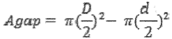
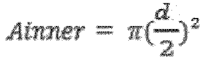
- the cylindrical inductor actually has an inner diameter and an outer diameter, it may be reasonable to simplify the description of the inductor by introducing the median diameter d, as illustrated in figure 6 .
- the median diameter may be the average value of the inner diameter and the outer diameter of the cylindrical inductor.
- the inductor has a median diameter d.
- the cross sectional area of the inductor up to a circle defined by the median diameter d of the inductor is denoted Ainner.
- the cross sectional gap area Agap between the circle defined by the median diameter of the inductor and the circular inner wall of the well pipe (production tube 3) is denoted Agap.
- the cross sectional area Agap is substantially equal to the sectional area Ainner.
- substantially equal may, e.g. mean that the ratio between the cross sectional gap area Agap and the inner cross sectional area Ainner is in the range 0.9 to 1.1. More advantageously, the area ratio may be in the range 0.95 to 1.05, and even more advantageously, the area ratio may be in the range 0.98 to 1.02.
- the cross sectional gap area Agap is equal to the inner cross sectional area Ainner.
- the well tool 10 may advantageously comprise a centralizing device which is configured to positioning the well tool 10 in a central position within the well pipe.
- the inductor may advantageously have an inductance in the range of 10 * 10 -6 H to 40*10 -6 H.
- the power supply device may advantageously comprise a capacitor, c, connected to the inductor, Ls, wherein the capacitor, c, is configured to discharge its energy over the inductor.
- the power supply device may comprise a switch, s, connected between the inductor Ls and the capacitor c.
- the well tool 10 is provided for determining or measuring the presence or absence of cement in an annular area between two concentric pipes in a hydrocarbon well.
- the well tool comprises a tool housing 11, a pulse generator 14 provided within the tool housing 1 for generating a magnetic field, where the pulse generator 14 comprises an inductor, Ls, and a power supply device, HV, c, for supplying electrical power to the inductor Ls and thereby providing that an electromagnetic pulse is generated, in such a way that the electromagnetic pulse provides physical vibrations in the pipe being closest to the pulse generator 14.
- the well tool further comprises at least one signal recorder 16 provided within the tool housing 11 for recording reflected acoustic signals from the well.
- a first distance, H1 between the signal recorder 16 and the pulse generator 14 is substantially equal to a second distance, H2, between the pulse generator 14 and the annular area.
- substantially equal may, e.g. mean that the ratio between the first distance H1 and the second distance H2 is in the range 0.7 to 1.3. More advantageously, the distance ratio may be in the range 0.9 to 1.1, and even more advantageously, the distance ratio may be in the range 0.95 to 1.05.
- the first distance H1 and the second distance H2 are equal.
- the well tool 10 may comprise a centralizing device which is configured to positioning the tool 10 in a central position within the well pipe.
- the second distance H2 may advantageously be measured in a radial direction in relation to the well from the center axis of the inductor Ls and the center of the annular area.
- the well tool 10 may advantageously be provided in the innermost pipe of the well.
- the pulse generator 14 may e.g. be located at a distance between 10 and 20 cm from the signal recorder 16.
- the well tool 10 may comprise an ultrasonic absorber 15 located between the pulse generator 14 and the signal recorder 16.
- the signal recorder may be located above the pulse generator.
- a second signal recorder may also be arranged, and in particular, it may be located in close proximity to the first signal recorder.
- a third signal recorder may also be arranged, and in particular, it may be located below the pulse generator, at the distance substantially equal to or equal to H1 below the pulse generator.
- the tool 10 may thus comprise signal recorder(s) 16, 17, 18 for recording signals representing the vibrations being reflected back from the pipes in the well. Since acoustic signals are investigated, a preferred signal recorder may be a hydrophone. The tool 10 may be held in a central position by centralizers (not shown). The pulse generator 14 and the signal recorder(s) 16, 17, 18 are provided within the housing 11.
- the pulse generator 14 is housed within the tool 10 that may further comprise a power supply and charging device 22 and a data storage system 24. Further, the tool may comprise a cable head 26 for attaching the tool to a cable 30.
- the cable 30 may provide communication between the tool and a surface equipment that may e.g. comprise a first control unit 32 for the control of the tool, and a second control unit 34 for receiving and processing data from the tool.
- An sound absorber may be located between the pulse generator 14 and the signal recorder(s) and may be used to prevent acoustic pulses from the inductor to reach the signal recorder and create noise in the system.
- the tool may be coupled to a tractor 20 or similar device for moving the tool in the well.
- Fig. 3 there are shown three signal recorders. However, there may be only one located above or below the signal generator or there may be one located above and one located below. In a preferred embodiment there is only one signal recorder which preferably is located above the signal generator.
- the distance between the pulse generator and the signal receiver in relation to the distance to the target may have significant effect.
- the outward waves travels outwards to the D annulus and get reflected back as acoustic waves to the signal recorder.
- the distances involved are very small.
- the standard nominal diameter of a surface casing is 20 inches (50 cm) and a normal size for the conductor casing is 30 inches (75 cm). If we regard the center of the well as the datum, the signals will only have traveled 25 - 35 cm before they reach the surface casing resp. the conductor pipe.
- the distance H1 between the pulse generator 14 and the closest signal receiver 16 is indicated.
- the distance H2 between the pulse generator 14 and the D annulus is indicated. More specifically, the distance H2 is indicating the horizontal distance between the center axis of the pulse generator 14 and the center of the D annulus.
- the applicant has found that a particularly advantageous result is obtained when the distance H1 between the pulse generator and the signal recorder is substantially equal to, or equal to, the distance H2 between the pulse generator and the annulus being analyzed.
- the signal recorder should be located about 30 cm from the pulse generator when the D annulus is analyzed. But a small deviation from this is possible so between 20 and 40 cm will still enable a good separation of reflected signals.
- the signal recorders both above and below the pulse generator they should both be the same distance (H1) from the pulse generator.
- the signal recorders In the case of having two signal recorders located above the pulse generator (as shown in Fig. 3 ) they are preferably placed as close to each other as possible. Arrangements with several signal recorders enables recordings to be compared with each other and can be used to check for anomalies or to find (and eliminate) noise. Another possibility is as use as backup in case of failure.
- the pulse generator 14 comprises a charging device, for example a high voltage power supply HV for charging an energy storage device, for example a capacitor C.
- the capacitor C is connected to a series connection of a switching device S, at least one inductor L and a resistor device R.
- the at least one inductor L is represented by a first inductor Ls and a second inductor Li.
- the second inductor Li is shown only to illustrate self inductance, i.e. internal inductance in the pulse generator 14.
- the switch is turned off.
- the voltage Uo is applied by the high voltage power supply HV to the capacitor C for charging the capacitor.
- the switch is turned on, and the capacitor C will discharge by supplying a current I through the inductor MS and the resistor R.
- the current through the magnetic inductor MS generates the electromagnetic signal pulse which will result in mechanical action on the pipes in the well.
- the inductor MS comprises a coil 42 with a number of turns, where the number of turns is determining the electromagnetic discharge characteristics.
- a supporting sleeve 43 (shown in fig. 6 ) may be arranged to support the coil 42 during use and also during production of the coil. When current passes through the inductor Ls it will produce a magnetic field as shown in the figure 5 .
- the requirements of the elements of the pulse generator 14 will depend on the desired parameters of the generated electromagnetic pulse and the characteristics of the system it is being used in.
- Inductance results from the magnetic field forming around a current-carrying conductor. Electric current through the conductor creates a magnetic flux proportional to the current. A change in this current creates a corresponding change in magnetic flux which, in turn, by Faraday's law generates an electromotive force (EMF) in the conductor that opposes this change in current. Thus inductors oppose changes in current through them. Inductance is a measure of the amount of EMF generated per unit change in current. For example, an inductor with an inductance of 1 Henry produces an EMF of 1 volt when the current through the inductor changes at the rate of 1 ampere per second. It is this electromotive force that is exploited in the invention. When the inductor is placed within a pipe having magnetic properties, the magnetic pressure from the inductor is converted into a mechanical pressure that sets the pipe in motion, as shown in Fig. 5 .
- An inductor is usually constructed as a coil of conducting material, typically copper wire, wrapped around a core either of air or of ferromagnetic or non-ferromagnetic material. When current is delivered through the inductor, magnetic field lines will form around the coil as shown in Fig. 4 .
- inductance in Henry is presented by the general formula for a type of induction coil called an "air core coil".
- L ⁇ 0 K N 2 A l
- the present invention may, in an exemplary aspect, use an "air core coil” that does not use a magnetic core made of a ferromagnetic material.
- the term also refers to coils wound on plastic, ceramic, or other nonmagnetic forms. Air core coils have lower inductance than ferromagnetic core coils. If the coil is not placed into a conductive pipe the field lines inside the inductor will be closer together and therefore the field will be stronger on the inside than outside. This kind of coil directs the magnetic pressure outwards, i.e. the magnetic pressure acts to the inductor extending it in a radial direction.
- the inductor When the inductor is placed within a conductive screen, e.g. a metal pipe such as tubing the field in the gap between the inductor and pipe will be much stronger than inside the inductor. This effect will depend on the size of the gap and will be strongest when the gap is small.
- the magnetic pressure then acts to the inductor compressing it in the radial direction.
- Parameters g, d and 1 are exemplary illustrated in fig. 6 .
- the housing 11 of the tool has been removed for clarity and ease of understanding.
- the inventors have found that particularly advantageous result for limiting noise in the recorded signals depends on the position of the first inductor Ls and also the size of the inductor Ls in relation to the conductive pipe. This is realized when the cross sectional area of the annular gap area around the coil is equal to the cross sectional area of the inductor inner cross section.
- the field value in the gap is nearly equal to the field inside the inductor.
- Magnetic pressure will then act on the inductor in the radial direction equally from both sides.
- the inductor is mechanically balanced and has minimal displacement. This results in minimal inductor acoustic emission and hence less noise in the received signals.
- FIG. 6 Such an exemplary design of the coil is illustrated in Fig. 6 .
- the coil 42 of the first inductor Ls is here placed inside a conductive pipe which in this example is the production tubing 3.
- the coil may be wound around a supporting sleeve 26 of a non-conductive material.
- the length of the inductor is 1.
- a conductive (metallic) cylinder is arranged inside the coil. This will function as a balancing element, allowing equalized magnetic pressures inside and outside coil. Due to its mechanical strength it will actually not generate acoustic noise itself. In this case the gap between coil and pipe can be reduced and this may result in lower energy consumption needed for generating of strong enough magnetic field.
- the pulse generator In use, the pulse generator is charged up, and when the switch is closed, the inductor will discharge an electromagnetic pulse.
- the pulse will transmit to the pipe and set the pipe in oscillation. This oscillation excites from the pipe and propagates as pressure pulses through the layers of pipes. As it reaches each layer the pipes will be set in motion and this motion creates acoustic waves that will be reflected back and be recorded by the signal recorder.
- the switch is turned off.
- the voltage Uo is applied over the capacitor C for charging the capacitor until a voltage of 3 - 15 kV is achieved, as mentioned above.
- the voltage Uo is applied via the wire 12.
- the switch is turned on, and the capacitor will discharge by supplying a current I through the magnetic device L and the resistor R.
- the switch was turned on for periods between 20 - 200 ⁇ s. Even shorter periods of 4 - 20 ⁇ s have also been tested. This short duration is achieved by the geometry of the coil.
- the current I will, with the values given above, have an amplitude value in the range of 5 - 20 kA.
- the current through the magnetic device MS will generate an electromagnetic signal pulse which will result in mechanical oscillations of the pipes in the well.
- the best results were achieved with an energy of the electromagnetic signal of 0,1 - 3 kJ.
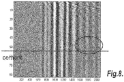
- a reflected signal is shown in Fig. 7 .
- the reflected signals coming from the nearest pipe(s) are very strong but get progressively weaker the further away from the signal recorder they are, in the graph this is shown as response time. Therefore, reflections from the area of the "D" annulus are very weak and difficult to interpret.
- the tool To determine where there is cement or where there is water the tool must be positioned at various locations in the tubing.
- the tool is positioned at a point in the well a distance below the inferred cement level location.
- the tool is then moved upwards at small intervals, preferably around 4 cm.
- the pulse generator is activated.
- a signal of the type shown in Fig. 7 is recorded by the signal recorder.
- Data representing the acoustic reflections is recorded by means of the signal recorder.
- the recorded data is transferred to the analyzing device 18 for performing the analysis.
- the output from the analyzing device is a time-delayed signal that is depicted as lines and curves on a monitor. But for further analysis a two dimensional matrix is used where the columns represent depth of the well and each row represents the time of returned signals. Each element will then show strength of signal. This matrix will be used for the subsequent 2D filtering, as discussed below.
- Fig. 8 there is shown a diagram of reflected signals after having positioned the tool at several locations and thereby representing the recorded signals from the total number of pulses.
- the vertical lines show the waves coming from the edges, i.e. the pipes. Since we know the strength of the signals, the speed of the acoustic waves and the dimensions of the system we can reliably predict which lines represent which pipe. This will give us a horizontal position of the pipe of interest (the conductor or surface casing).
- the signals are from an experimental setup with known cement/water boundary and it was known where the cement was (indicated by dashed line) and where the water was located (indicated by dashed circle). However, as seen in fig. 8 , it is not possible to see the difference between the signals representing water from signals representing cement. In fig. 8 , the darker lines representing the pipes 4, 5, 6 and 7 from fig. 1 are indicated.
Landscapes
- Engineering & Computer Science (AREA)
- Life Sciences & Earth Sciences (AREA)
- Geology (AREA)
- Mining & Mineral Resources (AREA)
- Physics & Mathematics (AREA)
- Environmental & Geological Engineering (AREA)
- Fluid Mechanics (AREA)
- General Life Sciences & Earth Sciences (AREA)
- Geochemistry & Mineralogy (AREA)
- Quality & Reliability (AREA)
- Geophysics (AREA)
- Geophysics And Detection Of Objects (AREA)
Claims (12)
- Système de forage comprenant un conduit de forage et un outil de forage (10) agencé à l'intérieur du conduit de forage, dans lequel l'outil de forage comprend :- un logement (11) ;- un générateur d'impulsions (14) disposé à l'intérieur du logement (11), le générateur d'impulsions (14) comprenant une bobine d'induction cylindrique (Ls), et un dispositif d'alimentation en énergie (HV, c) pour alimenter la bobine d'induction (L) en électricité et assurer ainsi qu'une impulsion électromagnétique soit générée, de sorte que, en fonctionnement, l'impulsion électromagnétique fournisse des vibrations physiques dans le conduit de forage ; la bobine d'induction comprenant un enroulement agencé axialement à l'intérieur du conduit de forage,caractérisé en ce que le rapport entre l'aire de la section du jeu, Agap, et l'aire de la section interne, Ainner, de la bobine d'induction (Ls) est dans la plage de 0,9 à 1,1, l'aire de la section du jeu, Agap, étant définie par
- Système de forage selon la revendication 1, dans lequel l'outil (10) comprend un dispositif de centrage configuré pour positionner l'outil de forage (10) dans une position centrée à l'intérieur du conduit de forage.
- Système de forage selon la revendication 1, dans lequel la bobine d'induction a une inductance dans la plage de 10*10-6 H à 40*10-6 H.
- Système de forage selon la revendication 1, dans lequel le dispositif d'alimentation en énergie (HV, c) comprend un condensateur (c) connecté à la bobine d'induction (Ls), le condensateur (c) étant configuré pour décharger son énergie dans la bobine d'induction.
- Système de forage selon la revendication 1, dans lequel le dispositif d'alimentation en énergie comprend un interrupteur (s) connecté entre la bobine d'induction (Ls) et le condensateur (c).
- Système de forage selon la revendication 1, dans lequel le conduit de forage est constitué d'un matériau magnétique.
- Système de forage selon la revendication 1, dans lequel la bobine d'induction comprend un noyau métallique.
- Système de forage selon la revendication 7, dans lequel le noyau métallique est un cylindre.
- Système de forage selon l'une des revendications 1 à 8, dans lequel le rapport entre l'aire de la section du jeu (Agap) et l'aire de la section interne (Ainner) est dans la plage de 0,95 à 1,05.
- Système de forage selon l'une des revendications 1 à 8, dans lequel le rapport entre l'aire de la section du jeu (Agap) et l'aire de la section interne (Ainner) est dans la plage de 0,98 à 1,02.
- Système de forage selon l'une des revendications 1 à 8, dans lequel l'aire de la section du jeu (Agap) est égale à l'aire de la section interne (Ainner).
- Procédé de génération de vibrations dans un conduit de forage, comprenant l'étape d'agencement d'un outil de forage (10) à l'intérieur du conduit de forage, l'outil de forage comprenant un logement (11), et un générateur d'impulsions (14) disposé à l'intérieur du logement (11), le générateur d'impulsions (14) comprenant une bobine d'induction (Ls), et un dispositif d'alimentation en énergie (HV, c), la bobine d'induction comprenant un enroulement agencé axialement à l'intérieur du conduit de forage, le procédé étant caractérisé en ce que le rapport entre l'aire de la section du jeu, Agap, et l'aire de la section interne, Ainner, de la bobine d'induction (Ls) est dans la plage de 0,9 à 1,1,
l'aire de la section du jeu, Agap, étant définie par

Priority Applications (1)
| Application Number | Priority Date | Filing Date | Title |
|---|---|---|---|
| EP14712630.4A EP2971460B1 (fr) | 2013-03-15 | 2014-03-17 | Outil de puits destiné à être utilisé dans un conduit de puits |
Applications Claiming Priority (3)
| Application Number | Priority Date | Filing Date | Title |
|---|---|---|---|
| PCT/EP2013/055404 WO2014139583A1 (fr) | 2013-03-15 | 2013-03-15 | Outil de puits à utiliser dans un tube de puits |
| EP14712630.4A EP2971460B1 (fr) | 2013-03-15 | 2014-03-17 | Outil de puits destiné à être utilisé dans un conduit de puits |
| PCT/EP2014/055290 WO2014140364A1 (fr) | 2013-03-15 | 2014-03-17 | Outil de puits destiné à être utilisé dans un conduit de puits |
Publications (2)
| Publication Number | Publication Date |
|---|---|
| EP2971460A1 EP2971460A1 (fr) | 2016-01-20 |
| EP2971460B1 true EP2971460B1 (fr) | 2017-02-01 |
Family
ID=54842936
Family Applications (1)
| Application Number | Title | Priority Date | Filing Date |
|---|---|---|---|
| EP14712630.4A Not-in-force EP2971460B1 (fr) | 2013-03-15 | 2014-03-17 | Outil de puits destiné à être utilisé dans un conduit de puits |
Country Status (1)
| Country | Link |
|---|---|
| EP (1) | EP2971460B1 (fr) |
Families Citing this family (1)
| Publication number | Priority date | Publication date | Assignee | Title |
|---|---|---|---|---|
| CN113236186B (zh) * | 2021-05-08 | 2022-07-19 | 东北石油大学 | 一种基于超声波技术的油井套管清蜡除垢装置 |
-
2014
- 2014-03-17 EP EP14712630.4A patent/EP2971460B1/fr not_active Not-in-force
Non-Patent Citations (1)
| Title |
|---|
| None * |
Also Published As
| Publication number | Publication date |
|---|---|
| EP2971460A1 (fr) | 2016-01-20 |
Similar Documents
| Publication | Publication Date | Title |
|---|---|---|
| US9759060B2 (en) | Proximity detection system for deep wells | |
| US8113298B2 (en) | Wireline communication system for deep wells | |
| US20210131276A1 (en) | System and Method to Obtain Vertical Seismic Profiles in Boreholes Using Distributed Acoustic Sensing on Optical Fiber Deployed Using Coiled Tubing | |
| US8553494B2 (en) | System for measuring stress in downhole tubulars | |
| EP2553218B1 (fr) | Procédé et appareil permettant de déterminer la nature d'un matériau dans une cavité entre une paroi métallique intérieure et une paroi métallique extérieure | |
| WO2019240952A1 (fr) | Procédés et appareil d'évaluation d'adhérence de ciment dans une colonne de production | |
| US10047601B2 (en) | Moving system | |
| JPH07280947A (ja) | 岩盤構造の浸透性を評価および/または測定するための方法および装置 | |
| US9581012B2 (en) | Well tool for use in a well pipe | |
| EP3552009B1 (fr) | Évaluation des propriétés physiques d'un matériau derrière un tubage à l'aide d'ondes acoustiques guidées | |
| EP2971490B1 (fr) | Procédé de détermination d'une position d'une limite eau/ciment entre des conduites dans un puits d'hydrocarbures | |
| WO2019232016A1 (fr) | Débitmètre de fond de trou | |
| EP2971460B1 (fr) | Outil de puits destiné à être utilisé dans un conduit de puits | |
| WO2014140363A2 (fr) | Procédé de détermination d'une position d'une limite eau/ciment entre des tuyaux dans un puits d'hydrocarbures | |
| WO2014139584A1 (fr) | Outil de puits | |
| EP2971492A2 (fr) | Procédé de détermination d'une position d'une limite eau/ciment entre des tuyaux dans un puits d'hydrocarbures | |
| WO2023277931A1 (fr) | Imagerie structurale dans le domaine temporel indépendante d'une vitesse d'espace annulaire dans des puits tubés à l'aide de données d'ondes de flexion secondaires à décalages multiples | |
| US20250250894A1 (en) | Conformal space filling coils |
Legal Events
| Date | Code | Title | Description |
|---|---|---|---|
| PUAI | Public reference made under article 153(3) epc to a published international application that has entered the european phase |
Free format text: ORIGINAL CODE: 0009012 |
|
| 17P | Request for examination filed |
Effective date: 20151009 |
|
| AK | Designated contracting states |
Kind code of ref document: A1 Designated state(s): AL AT BE BG CH CY CZ DE DK EE ES FI FR GB GR HR HU IE IS IT LI LT LU LV MC MK MT NL NO PL PT RO RS SE SI SK SM TR |
|
| AX | Request for extension of the european patent |
Extension state: BA ME |
|
| DAX | Request for extension of the european patent (deleted) | ||
| GRAP | Despatch of communication of intention to grant a patent |
Free format text: ORIGINAL CODE: EPIDOSNIGR1 |
|
| INTG | Intention to grant announced |
Effective date: 20161019 |
|
| STAA | Information on the status of an ep patent application or granted ep patent |
Free format text: STATUS: GRANT OF PATENT IS INTENDED |
|
| GRAS | Grant fee paid |
Free format text: ORIGINAL CODE: EPIDOSNIGR3 |
|
| GRAA | (expected) grant |
Free format text: ORIGINAL CODE: 0009210 |
|
| STAA | Information on the status of an ep patent application or granted ep patent |
Free format text: STATUS: THE PATENT HAS BEEN GRANTED |
|
| AK | Designated contracting states |
Kind code of ref document: B1 Designated state(s): AL AT BE BG CH CY CZ DE DK EE ES FI FR GB GR HR HU IE IS IT LI LT LU LV MC MK MT NL NO PL PT RO RS SE SI SK SM TR |
|
| REG | Reference to a national code |
Ref country code: GB Ref legal event code: FG4D |
|
| REG | Reference to a national code |
Ref country code: CH Ref legal event code: EP Ref country code: AT Ref legal event code: REF Ref document number: 865780 Country of ref document: AT Kind code of ref document: T Effective date: 20170215 |
|
| REG | Reference to a national code |
Ref country code: IE Ref legal event code: FG4D |
|
| REG | Reference to a national code |
Ref country code: DE Ref legal event code: R096 Ref document number: 602014006579 Country of ref document: DE |
|
| REG | Reference to a national code |
Ref country code: FR Ref legal event code: PLFP Year of fee payment: 4 |
|
| REG | Reference to a national code |
Ref country code: NL Ref legal event code: MP Effective date: 20170201 |
|
| REG | Reference to a national code |
Ref country code: LT Ref legal event code: MG4D Ref country code: NO Ref legal event code: T2 Effective date: 20170201 |
|
| REG | Reference to a national code |
Ref country code: AT Ref legal event code: MK05 Ref document number: 865780 Country of ref document: AT Kind code of ref document: T Effective date: 20170201 |
|
| PG25 | Lapsed in a contracting state [announced via postgrant information from national office to epo] |
Ref country code: LT Free format text: LAPSE BECAUSE OF FAILURE TO SUBMIT A TRANSLATION OF THE DESCRIPTION OR TO PAY THE FEE WITHIN THE PRESCRIBED TIME-LIMIT Effective date: 20170201 Ref country code: FI Free format text: LAPSE BECAUSE OF FAILURE TO SUBMIT A TRANSLATION OF THE DESCRIPTION OR TO PAY THE FEE WITHIN THE PRESCRIBED TIME-LIMIT Effective date: 20170201 Ref country code: GR Free format text: LAPSE BECAUSE OF FAILURE TO SUBMIT A TRANSLATION OF THE DESCRIPTION OR TO PAY THE FEE WITHIN THE PRESCRIBED TIME-LIMIT Effective date: 20170502 Ref country code: IS Free format text: LAPSE BECAUSE OF FAILURE TO SUBMIT A TRANSLATION OF THE DESCRIPTION OR TO PAY THE FEE WITHIN THE PRESCRIBED TIME-LIMIT Effective date: 20170601 Ref country code: HR Free format text: LAPSE BECAUSE OF FAILURE TO SUBMIT A TRANSLATION OF THE DESCRIPTION OR TO PAY THE FEE WITHIN THE PRESCRIBED TIME-LIMIT Effective date: 20170201 |
|
| PGFP | Annual fee paid to national office [announced via postgrant information from national office to epo] |
Ref country code: FR Payment date: 20170428 Year of fee payment: 4 Ref country code: NO Payment date: 20170427 Year of fee payment: 4 |
|
| PG25 | Lapsed in a contracting state [announced via postgrant information from national office to epo] |
Ref country code: AT Free format text: LAPSE BECAUSE OF FAILURE TO SUBMIT A TRANSLATION OF THE DESCRIPTION OR TO PAY THE FEE WITHIN THE PRESCRIBED TIME-LIMIT Effective date: 20170201 Ref country code: SE Free format text: LAPSE BECAUSE OF FAILURE TO SUBMIT A TRANSLATION OF THE DESCRIPTION OR TO PAY THE FEE WITHIN THE PRESCRIBED TIME-LIMIT Effective date: 20170201 Ref country code: ES Free format text: LAPSE BECAUSE OF FAILURE TO SUBMIT A TRANSLATION OF THE DESCRIPTION OR TO PAY THE FEE WITHIN THE PRESCRIBED TIME-LIMIT Effective date: 20170201 Ref country code: BG Free format text: LAPSE BECAUSE OF FAILURE TO SUBMIT A TRANSLATION OF THE DESCRIPTION OR TO PAY THE FEE WITHIN THE PRESCRIBED TIME-LIMIT Effective date: 20170501 Ref country code: PT Free format text: LAPSE BECAUSE OF FAILURE TO SUBMIT A TRANSLATION OF THE DESCRIPTION OR TO PAY THE FEE WITHIN THE PRESCRIBED TIME-LIMIT Effective date: 20170601 Ref country code: NL Free format text: LAPSE BECAUSE OF NON-PAYMENT OF DUE FEES Effective date: 20170201 Ref country code: RS Free format text: LAPSE BECAUSE OF FAILURE TO SUBMIT A TRANSLATION OF THE DESCRIPTION OR TO PAY THE FEE WITHIN THE PRESCRIBED TIME-LIMIT Effective date: 20170201 Ref country code: LV Free format text: LAPSE BECAUSE OF FAILURE TO SUBMIT A TRANSLATION OF THE DESCRIPTION OR TO PAY THE FEE WITHIN THE PRESCRIBED TIME-LIMIT Effective date: 20170201 Ref country code: PL Free format text: LAPSE BECAUSE OF FAILURE TO SUBMIT A TRANSLATION OF THE DESCRIPTION OR TO PAY THE FEE WITHIN THE PRESCRIBED TIME-LIMIT Effective date: 20170201 |
|
| PGFP | Annual fee paid to national office [announced via postgrant information from national office to epo] |
Ref country code: IT Payment date: 20170331 Year of fee payment: 4 |
|
| REG | Reference to a national code |
Ref country code: DE Ref legal event code: R119 Ref document number: 602014006579 Country of ref document: DE |
|
| PG25 | Lapsed in a contracting state [announced via postgrant information from national office to epo] |
Ref country code: RO Free format text: LAPSE BECAUSE OF FAILURE TO SUBMIT A TRANSLATION OF THE DESCRIPTION OR TO PAY THE FEE WITHIN THE PRESCRIBED TIME-LIMIT Effective date: 20170201 Ref country code: CZ Free format text: LAPSE BECAUSE OF FAILURE TO SUBMIT A TRANSLATION OF THE DESCRIPTION OR TO PAY THE FEE WITHIN THE PRESCRIBED TIME-LIMIT Effective date: 20170201 Ref country code: EE Free format text: LAPSE BECAUSE OF FAILURE TO SUBMIT A TRANSLATION OF THE DESCRIPTION OR TO PAY THE FEE WITHIN THE PRESCRIBED TIME-LIMIT Effective date: 20170201 Ref country code: SK Free format text: LAPSE BECAUSE OF FAILURE TO SUBMIT A TRANSLATION OF THE DESCRIPTION OR TO PAY THE FEE WITHIN THE PRESCRIBED TIME-LIMIT Effective date: 20170201 |
|
| REG | Reference to a national code |
Ref country code: CH Ref legal event code: PL |
|
| PG25 | Lapsed in a contracting state [announced via postgrant information from national office to epo] |
Ref country code: SM Free format text: LAPSE BECAUSE OF FAILURE TO SUBMIT A TRANSLATION OF THE DESCRIPTION OR TO PAY THE FEE WITHIN THE PRESCRIBED TIME-LIMIT Effective date: 20170201 Ref country code: MC Free format text: LAPSE BECAUSE OF FAILURE TO SUBMIT A TRANSLATION OF THE DESCRIPTION OR TO PAY THE FEE WITHIN THE PRESCRIBED TIME-LIMIT Effective date: 20170201 Ref country code: DK Free format text: LAPSE BECAUSE OF FAILURE TO SUBMIT A TRANSLATION OF THE DESCRIPTION OR TO PAY THE FEE WITHIN THE PRESCRIBED TIME-LIMIT Effective date: 20170201 |
|
| PLBE | No opposition filed within time limit |
Free format text: ORIGINAL CODE: 0009261 |
|
| STAA | Information on the status of an ep patent application or granted ep patent |
Free format text: STATUS: NO OPPOSITION FILED WITHIN TIME LIMIT |
|
| REG | Reference to a national code |
Ref country code: IE Ref legal event code: MM4A |
|
| 26N | No opposition filed |
Effective date: 20171103 |
|
| PG25 | Lapsed in a contracting state [announced via postgrant information from national office to epo] |
Ref country code: LU Free format text: LAPSE BECAUSE OF NON-PAYMENT OF DUE FEES Effective date: 20170317 Ref country code: DE Free format text: LAPSE BECAUSE OF NON-PAYMENT OF DUE FEES Effective date: 20171003 |
|
| PG25 | Lapsed in a contracting state [announced via postgrant information from national office to epo] |
Ref country code: IE Free format text: LAPSE BECAUSE OF NON-PAYMENT OF DUE FEES Effective date: 20170317 Ref country code: LI Free format text: LAPSE BECAUSE OF NON-PAYMENT OF DUE FEES Effective date: 20170331 Ref country code: CH Free format text: LAPSE BECAUSE OF NON-PAYMENT OF DUE FEES Effective date: 20170331 Ref country code: SI Free format text: LAPSE BECAUSE OF FAILURE TO SUBMIT A TRANSLATION OF THE DESCRIPTION OR TO PAY THE FEE WITHIN THE PRESCRIBED TIME-LIMIT Effective date: 20170201 |
|
| REG | Reference to a national code |
Ref country code: BE Ref legal event code: MM Effective date: 20170331 |
|
| PG25 | Lapsed in a contracting state [announced via postgrant information from national office to epo] |
Ref country code: BE Free format text: LAPSE BECAUSE OF NON-PAYMENT OF DUE FEES Effective date: 20170331 |
|
| PG25 | Lapsed in a contracting state [announced via postgrant information from national office to epo] |
Ref country code: MT Free format text: LAPSE BECAUSE OF NON-PAYMENT OF DUE FEES Effective date: 20170317 |
|
| REG | Reference to a national code |
Ref country code: NO Ref legal event code: MMEP |
|
| GBPC | Gb: european patent ceased through non-payment of renewal fee |
Effective date: 20180317 |
|
| PG25 | Lapsed in a contracting state [announced via postgrant information from national office to epo] |
Ref country code: NO Free format text: LAPSE BECAUSE OF NON-PAYMENT OF DUE FEES Effective date: 20180331 |
|
| PG25 | Lapsed in a contracting state [announced via postgrant information from national office to epo] |
Ref country code: GB Free format text: LAPSE BECAUSE OF NON-PAYMENT OF DUE FEES Effective date: 20180317 Ref country code: IT Free format text: LAPSE BECAUSE OF NON-PAYMENT OF DUE FEES Effective date: 20180317 |
|
| PG25 | Lapsed in a contracting state [announced via postgrant information from national office to epo] |
Ref country code: FR Free format text: LAPSE BECAUSE OF NON-PAYMENT OF DUE FEES Effective date: 20180331 |
|
| PG25 | Lapsed in a contracting state [announced via postgrant information from national office to epo] |
Ref country code: HU Free format text: LAPSE BECAUSE OF FAILURE TO SUBMIT A TRANSLATION OF THE DESCRIPTION OR TO PAY THE FEE WITHIN THE PRESCRIBED TIME-LIMIT; INVALID AB INITIO Effective date: 20140317 |
|
| PG25 | Lapsed in a contracting state [announced via postgrant information from national office to epo] |
Ref country code: CY Free format text: LAPSE BECAUSE OF FAILURE TO SUBMIT A TRANSLATION OF THE DESCRIPTION OR TO PAY THE FEE WITHIN THE PRESCRIBED TIME-LIMIT Effective date: 20170201 |
|
| PG25 | Lapsed in a contracting state [announced via postgrant information from national office to epo] |
Ref country code: MK Free format text: LAPSE BECAUSE OF FAILURE TO SUBMIT A TRANSLATION OF THE DESCRIPTION OR TO PAY THE FEE WITHIN THE PRESCRIBED TIME-LIMIT Effective date: 20170201 |
|
| PG25 | Lapsed in a contracting state [announced via postgrant information from national office to epo] |
Ref country code: TR Free format text: LAPSE BECAUSE OF FAILURE TO SUBMIT A TRANSLATION OF THE DESCRIPTION OR TO PAY THE FEE WITHIN THE PRESCRIBED TIME-LIMIT Effective date: 20170201 |
|
| PG25 | Lapsed in a contracting state [announced via postgrant information from national office to epo] |
Ref country code: AL Free format text: LAPSE BECAUSE OF FAILURE TO SUBMIT A TRANSLATION OF THE DESCRIPTION OR TO PAY THE FEE WITHIN THE PRESCRIBED TIME-LIMIT Effective date: 20170201 |