EP2973616B1 - Terminal hermétique haute pression - Google Patents
Terminal hermétique haute pression Download PDFInfo
- Publication number
- EP2973616B1 EP2973616B1 EP13878381.6A EP13878381A EP2973616B1 EP 2973616 B1 EP2973616 B1 EP 2973616B1 EP 13878381 A EP13878381 A EP 13878381A EP 2973616 B1 EP2973616 B1 EP 2973616B1
- Authority
- EP
- European Patent Office
- Prior art keywords
- reinforcing member
- top wall
- terminal
- pin
- opening
- Prior art date
- Legal status (The legal status is an assumption and is not a legal conclusion. Google has not performed a legal analysis and makes no representation as to the accuracy of the status listed.)
- Not-in-force
Links
- 230000003014 reinforcing effect Effects 0.000 claims description 61
- 239000003566 sealing material Substances 0.000 claims description 25
- 239000002184 metal Substances 0.000 claims description 24
- 238000004519 manufacturing process Methods 0.000 claims description 17
- 238000000034 method Methods 0.000 claims description 17
- 238000005304 joining Methods 0.000 claims description 12
- 238000010438 heat treatment Methods 0.000 claims description 5
- 239000000463 material Substances 0.000 claims description 4
- 239000000945 filler Substances 0.000 claims description 3
- 230000002787 reinforcement Effects 0.000 claims description 2
- 238000007789 sealing Methods 0.000 claims 1
- 239000005394 sealing glass Substances 0.000 description 5
- 229910000831 Steel Inorganic materials 0.000 description 4
- 238000005219 brazing Methods 0.000 description 4
- 238000005476 soldering Methods 0.000 description 4
- 239000010959 steel Substances 0.000 description 4
- 230000007547 defect Effects 0.000 description 3
- 238000004378 air conditioning Methods 0.000 description 2
- 239000000919 ceramic Substances 0.000 description 2
- 239000010960 cold rolled steel Substances 0.000 description 2
- 238000010276 construction Methods 0.000 description 2
- 239000012212 insulator Substances 0.000 description 2
- 238000003754 machining Methods 0.000 description 2
- 239000007769 metal material Substances 0.000 description 2
- 230000004323 axial length Effects 0.000 description 1
- 239000011248 coating agent Substances 0.000 description 1
- 238000000576 coating method Methods 0.000 description 1
- 238000005516 engineering process Methods 0.000 description 1
- 239000011521 glass Substances 0.000 description 1
- 238000012986 modification Methods 0.000 description 1
- 230000004048 modification Effects 0.000 description 1
- 239000000615 nonconductor Substances 0.000 description 1
- 230000001681 protective effect Effects 0.000 description 1
- 239000003507 refrigerant Substances 0.000 description 1
- 229920002379 silicone rubber Polymers 0.000 description 1
- 239000004945 silicone rubber Substances 0.000 description 1
- 239000010935 stainless steel Substances 0.000 description 1
- 229910001220 stainless steel Inorganic materials 0.000 description 1
Images


Classifications
-
- H—ELECTRICITY
- H01—ELECTRIC ELEMENTS
- H01R—ELECTRICALLY-CONDUCTIVE CONNECTIONS; STRUCTURAL ASSOCIATIONS OF A PLURALITY OF MUTUALLY-INSULATED ELECTRICAL CONNECTING ELEMENTS; COUPLING DEVICES; CURRENT COLLECTORS
- H01R13/00—Details of coupling devices of the kinds covered by groups H01R12/70 or H01R24/00 - H01R33/00
- H01R13/46—Bases; Cases
- H01R13/52—Dustproof, splashproof, drip-proof, waterproof, or flameproof cases
- H01R13/521—Sealing between contact members and housing, e.g. sealing insert
-
- F—MECHANICAL ENGINEERING; LIGHTING; HEATING; WEAPONS; BLASTING
- F04—POSITIVE - DISPLACEMENT MACHINES FOR LIQUIDS; PUMPS FOR LIQUIDS OR ELASTIC FLUIDS
- F04B—POSITIVE-DISPLACEMENT MACHINES FOR LIQUIDS; PUMPS
- F04B39/00—Component parts, details, or accessories, of pumps or pumping systems specially adapted for elastic fluids, not otherwise provided for in, or of interest apart from, groups F04B25/00 - F04B37/00
- F04B39/12—Casings; Cylinders; Cylinder heads; Fluid connections
- F04B39/121—Casings
-
- F—MECHANICAL ENGINEERING; LIGHTING; HEATING; WEAPONS; BLASTING
- F04—POSITIVE - DISPLACEMENT MACHINES FOR LIQUIDS; PUMPS FOR LIQUIDS OR ELASTIC FLUIDS
- F04B—POSITIVE-DISPLACEMENT MACHINES FOR LIQUIDS; PUMPS
- F04B53/00—Component parts, details or accessories not provided for in, or of interest apart from, groups F04B1/00 - F04B23/00 or F04B39/00 - F04B47/00
- F04B53/16—Casings; Cylinders; Cylinder liners or heads; Fluid connections
-
- H—ELECTRICITY
- H01—ELECTRIC ELEMENTS
- H01B—CABLES; CONDUCTORS; INSULATORS; SELECTION OF MATERIALS FOR THEIR CONDUCTIVE, INSULATING OR DIELECTRIC PROPERTIES
- H01B17/00—Insulators or insulating bodies characterised by their form
- H01B17/26—Lead-in insulators; Lead-through insulators
- H01B17/30—Sealing
- H01B17/303—Sealing of leads to lead-through insulators
-
- H—ELECTRICITY
- H01—ELECTRIC ELEMENTS
- H01R—ELECTRICALLY-CONDUCTIVE CONNECTIONS; STRUCTURAL ASSOCIATIONS OF A PLURALITY OF MUTUALLY-INSULATED ELECTRICAL CONNECTING ELEMENTS; COUPLING DEVICES; CURRENT COLLECTORS
- H01R43/00—Apparatus or processes specially adapted for manufacturing, assembling, maintaining, or repairing of line connectors or current collectors or for joining electric conductors
- H01R43/16—Apparatus or processes specially adapted for manufacturing, assembling, maintaining, or repairing of line connectors or current collectors or for joining electric conductors for manufacturing contact members, e.g. by punching and by bending
Definitions
- the present disclosure generally relates to hermetic power terminal feed-throughs, and more particularly to hermetic power terminal feed-throughs for use in high-pressure applications.
- FIG. 1 shows a schematic illustration of an A/C compressor 100 in which is installed a hermetic terminal 200 which enables electric power to be carried to a motor located within a sealed housing.
- the hermetic terminal is constructed to prevent the compressed, pressurized refrigerant gas 102 from escaping through the terminal 100.
- FIG. 2 An exemplary conventional hermetic terminal 200 that is well-known in the art is shown in FIG. 2 .
- an electrically conductive pin 202 is fixed in place within an aperture or opening 204 through a metal terminal body 206 by an electrically insulating fusible sealing glass 208 that forms a hermetic, glass-to-metal seal between the pin 202 and the terminal body 206.
- a ceramic insulating sleeve 210 surrounds each pin 202 on the interior side of the terminal body 206 and is secured in place by the sealing glass 208.
- a resilient electrical insulator 212 can optionally be bonded to the outside surface of the terminal body 206, as well as over the glass-to-metal seal 208 and portions of the current-conducting pins 202.
- the terminal body 206 is typically manufactured from cold rolled steel in a stamping operation that forms the cap-like shape of the terminal body 206, as well as the openings 204 through the top wall 214 of the terminal body.
- the openings 204 through the top wall 214 of the terminal body 206 are formed to create a lip portion 216 that serves as a surface against which the fusible sealing glass 208 can create the hermetic seal.
- the surface area created by the lip portion 216 which has a length extending about two times or more the thickness of the top wall 214 of the terminal body 206, ensures that a sufficient seal can be made to achieve a desired hermeticity.
- burst pressure is a critical performance specification for hermetic terminals, particularly those used in high-pressure applications.
- the performance requirements for high-pressure hermetic terminals often demand that the hermetic terminals be capable of maintaining hermeticity at pressures more than 20 MPa (i.e., several thousand pounds per square inch).
- hermetic terminals can be required to meet burst pressure ratings of 33 MPa (about 4800 psi). Any deformation of the terminal body under high pressure can compromise the integrity of the hermetic seal and result in failure of the hermetic terminal. Consequently, it is generally accepted that high-pressure hermetic terminals require a more robust (i.e., thicker) terminal body.
- the dimensions of the hermetic terminal in combination with limitations in stamping technology limit the maximum thickness of a terminal body that can be produced by a metal stamping process to only about 3.5 millimeters. Moreover, as the thickness of the material forming the terminal body increases toward 3.5 millimeters, the ability to form the lip portion in the opening (which provides the surface where hermetic seal can be made) during the stamping operation diminishes. Metal stamping has, therefore, been found to be unsuitable for forming a terminal body for a high-pressure hermetic terminal.
- high-pressure hermetic terminals generally incorporate a thicker terminal body.
- One exemplary high-pressure hermetic terminal 300 is illustrated in FIG. 3 .
- the top wall 314 of the terminal body 306 is substantially thicker t 2 than the thickness t 1 of the top wall 206 of the conventional hermetic terminal 200 of FIG. 2 , at least in part because of the need to provide adequate surface area for forming a sufficient hermetic seal.
- a terminal body 306 having a top wall thickness t 2 of about 6 millimeters has been found to demonstrate the necessary strength under high pressure, while providing the surface area needed to enable the sealing glass 308 to form an adequate hermetic seal with the terminal body 306.
- the thicker terminal body 306 cannot readily be manufactured in a cost-effective manufacturing operation such as metal stamping. Instead, the thicker terminal bodies 306 are generally fabricated in the more costly manufacturing process of machining from bar stock.
- the bar stock from which the terminal bodies 306 are machined can include defects in the form of inclusions that can run vertically through the thickness t 2 of the top wall 314 of the machined terminal body 306. The inclusions can, in turn, lead to defects that increase the scrap rates of the machined parts.
- the present disclosure provides a hermetic power terminal feed-through for use in high-pressure applications.
- the hermetic power terminal can include a fused pin subassembly comprising a tubular reinforcing member, including a rim portion seated against the top wall of the terminal body, and a current-conducting pin.
- the current-conducting pin passes through the tubular reinforcing member and can be fixed thereto by a fusible sealing material to create a hermetic seal.
- the fused pin subassembly can then be permanently joined and hermetically sealed to a terminal body by brazing or soldering.
- the construction of the hermetic terminal of the present disclosure enables the terminal body to be made from a metal material that is thinner than the metal material conventionally employed in high-pressure hermetic terminals. Notwithstanding the thinner terminal body, the hermetic seal provided and the strength of the terminal body satisfy the performance demands of a high-pressure operating environment. The reduced thickness of the terminal body makes it suitable for forming in the economical manufacturing process of metal stamping.
- US 2008/279703 discloses a hermetic terminal assembly.
- US 2429955 discloses a leak-proof insulating structure.
- the hermetic terminal 10 generally includes a terminal body 12, a reinforcing member 14, a current-conducting pin 16 and an electrically insulating fusible sealing material 18.
- the current-conducting pin 16 passes through and is fixed to the reinforcing member 14 by the fusible sealing material 18 that creates a hermetic seal between the pin 16 and the reinforcing member 14.
- the reinforcing member 14 is then permanently joined and hermetically sealed to a terminal body 12 by a joining process such as brazing or soldering.
- the hermetic terminal 10 can include a plurality of current-conducting pins 16, a plurality of reinforcing members 14 and a plurality of seals formed from the fusible sealing material 18.
- the exemplary hermetic terminal 10 is illustrated as having three current-conducting pins 16, each current-conducting pin 16 being hermetically sealed to a corresponding reinforcing member 14 which is, itself, hermetically joined to the terminal body 12. As shown, the current conducting pins 16 extend through the terminal body 12 from a first, interior side 20 of the terminal body 12 to a second, exterior side 22 of the terminal body 12.
- the terminal body 12 comprises a metal, generally cap-shaped structure and includes a substantially planar top wall 24, a cylindrical sidewall 26, and an annular lip 28 extending radially and outwardly from the sidewall 26.
- the top wall 24 defines a plurality of openings 30 for receiving the reinforcing members 14 and current-conducting pins 16, enabling the current-conducting pins 16 to pass through the terminal body 12.
- the terminal body 12 can be about 25 to about 40 millimeters in diameter.
- the thickness (T1) of the top wall 24 can be less than about 3.5 millimeters, and is preferably between 2.5 millimeters and 3.5 millimeters, and more preferably between 3.0 millimeters and 3.5 millimeters.
- the terminal body 12 can be made from cold-rolled or hot-rolled steel in a metal stamping manufacturing process.
- the reinforcing members 14 each comprise a body portion 32 having a hollow, tubular configuration extending for a length (L) along a longitudinal axis (X).
- the body portion 32 has a first, outer diameter, (D) a second, inner diameter (d) and a wall thickness (t).
- the outer diameter (D) is sized to closely fit within the opening 30 through the top wall 24 of the terminal body 12 such that the exterior surface of the body portion 32 is adjacent to the wall of the opening 30.
- the inner diameter (d) is sized to accommodate a current-conducting pin 16 passing through the reinforcing member 14 and the fusible sealing material 18 that creates the hermetic seal between the current-conducting pin 16 and the reinforcing member 14.
- the length (L) of the reinforcing member 14 is typically greater than the thickness (T1) of the upper wall 24 of the terminal body 12.
- the reinforcing member 14 provides for a seal surface along its inner diameter (d) that extends beyond the thickness (T1) of the upper wall 24 of the terminal body 12 and is, therefore, effective to create a hermetic seal with the fusible sealing material 18 and pin 16 that is suitable for use in a high-pressure operating environment.
- the reinforcing member 14 can include a flange or rim portion 34.
- the flange 34 can seat against the top wall 24 of the terminal body 12.
- the flange 34 of the reinforcing member 14 can seat against the exterior surface 36 of the top wall 24.
- the reinforcing member 14 can be installed in a manner such that the flange 34 seats against the interior surface 38 of the top wall 24.
- the flange 34 can aid in positioning the reinforcing member 14 relative to the terminal body 12 during the manufacture of the hermetic terminal 10.
- the flange 34 can serve as a structural reinforcement to the upper wall 24 of the terminal body 12, thereby increasing its resistance to deformation under the force generated in a high-pressure operating environment.
- the reinforcing member 14 can be made from metal, such as cold rolled steel or hot rolled steel.
- the reinforcing member 14 can have a coefficient of thermal expansion that matches the coefficient of thermal expansion of the fusible sealing material 18, the current-conducting pin 16, and the terminal body 12.
- Each current conducting pin 16 extends along the longitudinal axis (X) and is received within the reinforcing member 14.
- the current-conducting pin 16 is fixed in place relative to the reinforcing member 14 by the fusible sealing material 18.
- the current conducting pin 16 is preferably made from steel, stainless steel, or a copper-cored steel wire.
- the current conducting pin 16 can have a coefficient of thermal expansion that matches the coefficient of thermal expansion of the fusible sealing material 18, the reinforcing member 14, and the terminal body 12.
- the fusible sealing material 18 can comprise a fusible glass for creating a hermetic, glass-to-metal seal between the current-conducting pin 16 and the reinforcing member 14. Such materials are well-known in the field.
- the fusible sealing material 18 can have a coefficient of thermal expansion that matches the coefficient of thermal expansion of the reinforcing member 14, the current-conducting pin 16, and the terminal body 12.
- a significant advantage to the construction of the hermetic terminal 10 of the present disclosure is that a thinner terminal body 12 than is conventionally employed in a high-pressure hermetic terminal can be used in the hermetic terminal 10 of the present disclosure. Notwithstanding that its thinner, the hermetic seal provided and the strength of the terminal body 12 satisfy the performance demands of a high-pressure operating environment. Further, the reduced thickness of the terminal body 12 makes it suitable for forming the cap-shaped terminal body having one or more openings through the top wall in the more economical manufacturing process of metal stamping, as opposed to machining from bar stock as has been done previously. The metal stamping process can employ less expensive tools that can run at higher production speeds, thereby reducing manufacturing costs and increasing manufacturing output. Still further, terminal bodies formed in a metal stamping process generally do not exhibit the defects in the form of inclusions that can run vertically through the thickness of the top wall as in a machined terminal body.
- the process for manufacturing the hermetic terminal 10 of the present disclosure differs from that of prior hermetic terminal devices.
- the current-conducting pin 16 can be hermetically joined to the reinforcing member 14 by the fusible sealing material 18 to create a fused pin subassembly, prior to its assembly with the terminal body 12.
- the fusible sealing material 18 can be configured as a preformed tube.
- the pin 16, preformed tube 18, and reinforcing component 14 can then be arranged such that the preformed tube 18 is nested within the reinforcing component 14 and the pin 16 passes through the preformed tube 18 and reinforcing member 14.
- the arrangement is heated to the fusing temperature of the electrically insulating fusible sealing material 18 (i.e., about 1500 °F for fusible sealing glass). After heating, the assembly can then be cooled thereby creating the fused pin subassembly, with the pin 16 and reinforcing member 14 being joined by a hermetic seal created by the fusible sealing material 18.
- the fusing temperature of the electrically insulating fusible sealing material 18 i.e., about 1500 °F for fusible sealing glass.
- the fused pin subassembly can be installed in the terminal body 12 through the opening 30 in the top wall 24. Once positioned within the opening 30, the fused pin subassembly can be joined to the terminal body 12 by a joining process like brazing or soldering.
- the joining process provides a filler material that occupies the closely fitting space between the fused pin subassembly (e.g., the outer diameter (D) of the reinforcing member (14) and the opening 30) and adheres to both the reinforcing member 14 and the terminal body 12.
- the joining process creates a hermetic seal 39 between the fused pin subassembly and the terminal body 12.
- the hermetic seal can extend between the reinforcing member 14 and the opening 30 along the entire axial length of the opening 30 (i.e., the thickness of the top wall 24). Additionally, the hermetic seal 39 can extend between the flange 34 of the reinforcing member 14 (if a flange 34 forms part of the reinforcing member 14) and the exterior surface 36 (or interior surface 38 - depending on the orientation of the reinforcing member 14 in the opening 30) of the top wall 24 of the terminal body 12.
- This joining process generally can occur at a much lower temperature (e.g., about 840 °F) than the fusing temperature of the electrically insulating fusible sealing material and, therefore, the integrity of the hermetic seal between the pin 16 and reinforcing member 14 is not affected by the process.
- a much lower temperature e.g., about 840 °F
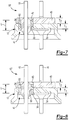
- FIGs. 7 and 8 Additional alternatives for the high-pressure hermetic terminal of the present disclosure 10' and 10" are shown in FIGs. 7 and 8 .
- a rigid pad 40 can be attached to the exterior surface 36 of the top wall 24 of the terminal body 12, either before or after the fused pin subassembly is joined to the terminal body 12.
- the rigid pad 40 can be generally disc-shaped and sized to substantially cover the exterior surface 35 of the top wall 24 of the terminal body 12.
- the rigid pad 40 can include one or more apertures 42 that are substantially aligned with the opening(s) 30 in the top wall 24 of the terminal body 12 for enabling the current-conducting pin(s) 16 to pass through the pad 40.
- the rigid pad 40 can have a thickness (T2) of less than or about the same thickness (T1) of the top wall 24 of the terminal body 12.
- T2 thickness of the top wall 24 of the terminal body 12.
- the combined thickness (T1 + T2) of the top wall 24 and the rigid pad 40 is slightly greater than the length (L) of the reinforcing member 14.
- the rigid pad 40 can provide additional structural support to the terminal body 12 further adapting the hermetic terminal 10' for use in high-pressure applications. As shown in FIGs. 7 and 8 , the pad 40 can be employed in addition to a reinforcing member 14, 14' (independent of whether or not the reinforcing member incorporates a flange 34).
- the pad 40 can be made from the same metal as the terminal body 12 and can be joined to the terminal body 12 by a joining process as previously described, such as by brazing or soldering.
- the power terminal feed-throughs may also incorporate additional features such as a protective oversurface coating (e.g., silicone rubber) on the terminal body, fuse portions integrated into the pins, additional insulators providing oversurface protection for the pins (e.g., ceramic insulators), and connectors adapted to connect the pins to other components.
- a protective oversurface coating e.g., silicone rubber
- fuse portions integrated into the pins e.g., fuse portions integrated into the pins
- additional insulators providing oversurface protection for the pins (e.g., ceramic insulators)
- connectors adapted to connect the pins to other components.
Landscapes
- Engineering & Computer Science (AREA)
- Mechanical Engineering (AREA)
- General Engineering & Computer Science (AREA)
- Manufacturing & Machinery (AREA)
- Connections Arranged To Contact A Plurality Of Conductors (AREA)
- Manufacturing Of Electrical Connectors (AREA)
- Compressor (AREA)
Claims (13)
- Terminal hermétique haute pression (10) destiné à être utilisé dans un environnement de fonctionnement haute pression comprenant :un corps métallique en forme de capuchon comprenant une paroi supérieure généralement plane (24) et une paroi latérale cylindrique (26), la paroi supérieure (24) comprenant une épaisseur et ayant une ouverture (30) s'étendant à travers cette dernière dans la direction d'un axe longitudinal, l'ouverture (30) comprenant une paroi latérale ayant une longueur égale à l'épaisseur de la paroi supérieure (24) ;dans lequel l'élément de renforcement (14) comprend une partie de corps (32) et une partie de rebord (34) située au niveau d'une extrémité de la partie de corps (32) et la partie de rebord (34) repose contre la paroi supérieure (24) du corps de terminal pour fournir un renforcement structurel de la paroi supérieure (24) afin d'augmenter la résistance de la paroi supérieure (24) à une déformation sous la force générée dans l'environnement de fonctionnement haute pression ;caractérisé en ce queun élément de renforcement tubulaire métallique (14) situé dans l'ouverture (30) et s'étendant le long de l'axe longitudinal, un diamètre externe de l'élément de renforcement (14) étant dimensionné de sorte à s'ajuster étroitement dans l'ouverture (30) de telle sorte qu'une surface extérieure de l'élément de renforcement (14) soit adjacente à une paroi de l'ouverture (30), l'élément de renforcement (14) étant relié au corps par un métal d'apport ;une broche conductrice de courant (16) s'étendant à travers l'élément de renforcement (14) le long de l'axe longitudinal ; etun matériau de scellement fusible électro-isolant (18) reliant et scellant hermétiquement la broche conductrice de courant (16) au renforcement.
- Terminal hermétique (10) selon la revendication 1, dans lequel l'élément de renforcement (14) présente une longueur dans la direction de l'axe longitudinal qui est plus importante que l'épaisseur de la paroi supérieure (24).
- Terminal hermétique (10) selon la revendication 1, dans lequel la partie de rebord (34) repose contre une surface extérieure de la paroi supérieure (24) du corps de terminal (12) .
- Terminal hermétique (10) selon la revendication 1, dans lequel la partie de rebord (34) repose contre une surface intérieure de la paroi supérieure (24) du corps de terminal (12) .
- Terminal hermétique (10) selon la revendication 1, comprenant en outre une pastille métallique rigide (40) fixée à la surface extérieure de la paroi supérieure (24) du corps de terminal (12).
- Terminal hermétique (10) selon la revendication 5, dans lequel la pastille (40) est dimensionnée de sorte à recouvrir la surface extérieure de la paroi supérieure (24) du corps de terminal (12) et comprend une/plusieurs ouvertures qui sont/est alignée (s) avec la ou les ouvertures (30) dans la paroi supérieure (24) du corps de terminal (12) dans la direction le long de l'axe longitudinal.
- Terminal hermétique (10) selon la revendication 6, dans lequel l'épaisseur combinée de la pastille (40) et de la paroi supérieure (24) du corps de terminal (12) est plus importante qu'une longueur de l'élément de renforcement (14).
- Procédé pour fabriquer un terminal hermétique haute pression (10) consistant :à former un corps métallique en forme de capuchon lors d'une opération d'estampage, dans lequel le corps comprend une paroi supérieure généralement plane (24) et une paroi latérale cylindrique (26), et dans lequel la paroi supérieure (24) présente une épaisseur allant de 2,5 mm à 3,5 mm et comprend au moins une ouverture (30) à travers cette dernière s'étendant le long d'un axe longitudinal ;à fournir un élément de renforcement tubulaire métallique (14) comprenant un corps ayant un diamètre externe dimensionné de sorte à s'ajuster étroitement dans l'ouverture (30) de telle sorte qu'une surface extérieure de l'élément de renforcement (14) soit adjacente à une paroi de l'ouverture (30), et un diamètre interne ;à fournir un matériau de scellement fusible électro-isolant (18) configuré sous la forme d'un tube préformé ayant un diamètre externe qui est dimensionné de sorte à s'ajuster dans le diamètre interne de l'élément de renforcement (14), et un diamètre interne ;à fournir une broche conductrice de courant (16) ayant un diamètre externe dimensionné de sorte à s'ajuster dans le diamètre interne du matériau de scellement (18) ;à placer le matériau de scellement (18) dans l'élément de renforcement (14) ;(18) ; à placer la broche (16) dans le matériau de scellementà raccorder de façon permanente la broche (16) à l'élément de renforcement (14) pour former un sous-ensemble broche fondu consistant à chauffer la broche (16), le matériau de scellement et l'élément de renforcement (14) à la température de fusion du matériau de scellement (18) ;à placer le sous-ensemble broche fondu dans l'ouverture (30) ; età raccorder de façon permanente le sous-ensemble broche fondu au corps.
- Procédé pour fabriquer un terminal hermétique haute pression (10) selon la revendication 8, dans lequel le raccordement permanent de la broche (16) à l'élément de renforcement (14) consiste à créer un joint d'étanchéité hermétique entre l'élément de renforcement (14) et la broche (16) ; et
dans lequel le raccordement permanent du sous-ensemble broche fondu au corps consiste à créer un joint d'étanchéité hermétique entre l'élément de renforcement (14) et le corps. - Procédé pour fabriquer un terminal hermétique haute pression (10) selon les revendications 8 ou 9, dans lequel le chauffage de la broche (16), du matériau de scellement (18) et de l'élément de renforcement (14) à la température de fusion du matériau de scellement (18) consiste à chauffer à environ 1 500 °F.
- Procédé pour fabriquer un terminal hermétique haute pression (10) selon les revendications 8, 9 ou 10, dans lequel le raccordement permanent du sous-ensemble broche fondu (16) au corps consiste à chauffer un matériau d'apport à environ 840 °F.
- Procédé pour fabriquer un terminal hermétique haute pression (10) selon les revendications 8 à 11, dans lequel la fourniture d'un élément de renforcement tubulaire métallique (14) consiste en outre à fournir un élément de renforcement métallique (14) comprenant un corps ayant une partie de rebord (34) située au niveau d'une extrémité ; et
dans lequel le placement du sous-ensemble broche fondu dans l'ouverture consiste à orienter le sous-ensemble broche fondu dans l'ouverture (30) de telle sorte que la partie de rebord (34) repose soit contre la surface extérieure, soit contre la surface intérieure de la paroi supérieure (24). - Procédé pour fabriquer un terminal hermétique haute pression (10) selon l'une quelconque des revendications 8 à 12, consistant en outre à fixer une pastille métallique rigide (40) à une surface extérieure de la paroi supérieure (24), la pastille comprenant une ouverture qui est alignée avec l'ouverture (30).
Applications Claiming Priority (2)
| Application Number | Priority Date | Filing Date | Title |
|---|---|---|---|
| US201361788762P | 2013-03-15 | 2013-03-15 | |
| PCT/US2013/064788 WO2014143179A1 (fr) | 2013-03-15 | 2013-10-14 | Terminal hermétique haute pression |
Publications (3)
| Publication Number | Publication Date |
|---|---|
| EP2973616A1 EP2973616A1 (fr) | 2016-01-20 |
| EP2973616A4 EP2973616A4 (fr) | 2016-11-23 |
| EP2973616B1 true EP2973616B1 (fr) | 2018-06-13 |
Family
ID=51537431
Family Applications (1)
| Application Number | Title | Priority Date | Filing Date |
|---|---|---|---|
| EP13878381.6A Not-in-force EP2973616B1 (fr) | 2013-03-15 | 2013-10-14 | Terminal hermétique haute pression |
Country Status (5)
| Country | Link |
|---|---|
| US (1) | US9979118B2 (fr) |
| EP (1) | EP2973616B1 (fr) |
| JP (2) | JP2016514355A (fr) |
| CN (1) | CN105190786B (fr) |
| WO (1) | WO2014143179A1 (fr) |
Families Citing this family (26)
| Publication number | Priority date | Publication date | Assignee | Title |
|---|---|---|---|---|
| WO2016155781A1 (fr) * | 2015-03-31 | 2016-10-06 | Arcelik Anonim Sirketi | Ensemble terminal à utiliser dans un compresseur hermétique |
| JP2017224493A (ja) * | 2016-06-15 | 2017-12-21 | 横河電機株式会社 | ハーメチック構造および製造方法 |
| CN106175015A (zh) * | 2016-08-26 | 2016-12-07 | 广州天罡投资管理有限公司 | 一种烫发机及烫发方法 |
| USD832794S1 (en) | 2017-01-17 | 2018-11-06 | Schott Japan Corporation | Hermetic terminal |
| USD832795S1 (en) | 2017-01-17 | 2018-11-06 | Schott Japan Corporation | Hermetic terminal |
| JP6943717B2 (ja) * | 2017-10-04 | 2021-10-06 | ヒロセ電機株式会社 | 電気コネクタおよび電気コネクタの製造方法 |
| DE102017221426A1 (de) | 2017-11-29 | 2019-05-29 | Schott Ag | Durchführung mit Flachleiter |
| FR3075490B1 (fr) * | 2017-12-15 | 2021-04-09 | Valeo Japan Co Ltd | Connecteur electrique pour un compresseur electrique d'une installation de conditionnement d'air |
| JP6835028B2 (ja) * | 2018-03-30 | 2021-02-24 | 横河電機株式会社 | 気密端子及びセンサユニット |
| JP7231339B2 (ja) * | 2018-06-01 | 2023-03-01 | ショット日本株式会社 | 気密端子 |
| DE102018126389B3 (de) * | 2018-10-23 | 2020-03-19 | Schölly Fiberoptic GmbH | Elektrische Durchführung und medizinisches Gerät |
| USD915292S1 (en) * | 2019-01-22 | 2021-04-06 | Dsm&T Company, Inc. | Electrical connector insert |
| CN209948088U (zh) * | 2019-07-15 | 2020-01-14 | 上海海立电器有限公司 | 一种接线装置及压缩机 |
| EP4007074B1 (fr) * | 2019-07-25 | 2025-10-01 | Kyocera Corporation | Borne hermétique |
| CN110492335B (zh) * | 2019-07-31 | 2021-01-19 | 深圳市宏讯实业有限公司 | 导电器制造工艺 |
| US12349300B2 (en) * | 2019-09-30 | 2025-07-01 | Kuwana Metals, Ltd. | Airtight connection unit, airtight connection assembly, airtight container and vaporizer, as well as production method of airtight connection assembly |
| DE102019130582A1 (de) * | 2019-11-13 | 2021-05-20 | Hanon Systems | Dichtanordnung einer Steckverbindung zum Steckverbinden elektrischer Anschlüsse und Vorrichtung zum Antreiben eines Verdichters mit der Dichtanordnung |
| USD929944S1 (en) | 2020-03-04 | 2021-09-07 | Colder Products Company | Coupling |
| USD929945S1 (en) | 2020-03-04 | 2021-09-07 | Colder Products Company | Coupling |
| JP7467273B2 (ja) * | 2020-08-07 | 2024-04-15 | ショット アクチエンゲゼルシャフト | 気密端子 |
| DE102022110839A1 (de) * | 2021-05-10 | 2022-11-10 | Hanon Systems | Durchführungs- und Abdichtungsanordnung |
| DE102023120482A1 (de) * | 2022-10-28 | 2024-05-08 | Hanon Systems | Dichtungsanordnung für eine Vorrichtung zum Antreiben eines Verdichters und Vorrichtung zum Antreiben eines Verdichters sowie ein Verfahren zum Herstellen einer Verbindungsanordnung |
| CN219303977U (zh) * | 2023-02-17 | 2023-07-04 | 艾默生电气(铜陵)有限公司 | 密封接线端子 |
| EP4530467A1 (fr) * | 2023-09-29 | 2025-04-02 | Schott Ag | Ensemble de traversée électrique à distance de fluage augmentée |
| US12456562B2 (en) * | 2024-01-31 | 2025-10-28 | Integrated Microwave Corporation | Ceramic RF feedthrough component |
| EP4717918A1 (fr) * | 2024-09-25 | 2026-04-01 | Schott Ag | Ensemble de traversée électrique |
Family Cites Families (22)
| Publication number | Priority date | Publication date | Assignee | Title |
|---|---|---|---|---|
| US2429955A (en) * | 1945-07-06 | 1947-10-28 | Electronic Mechanics Inc | Insulating structure |
| FR1057611A (fr) | 1951-08-03 | 1954-03-09 | Longford Engineering Company L | Borne électrique pour unités capsulées |
| JPS5437962Y2 (fr) | 1975-06-30 | 1979-11-13 | ||
| JPS5512376Y2 (fr) * | 1975-12-10 | 1980-03-18 | ||
| JPS576062Y2 (fr) | 1977-07-25 | 1982-02-04 | ||
| US4362792A (en) * | 1980-12-01 | 1982-12-07 | Emerson Electric Co. | Conductor seal assembly |
| JPS57155673U (fr) * | 1981-03-25 | 1982-09-30 | ||
| US4841101A (en) * | 1987-12-21 | 1989-06-20 | Pollock John A | Hermetically sealed feedthroughs and methods of making same |
| US4984973A (en) * | 1990-03-21 | 1991-01-15 | Tecumseh Products Company | Hermetic motor compressor unit having a hermetic terminal with electrically insulating anti-tracking cap |
| US5017740A (en) * | 1990-04-02 | 1991-05-21 | Emerson Electric Co. | Fused hermetic terminal assembly including a pin guard and lead wire end connection securing device associated therewith |
| US5227587A (en) * | 1991-05-13 | 1993-07-13 | Emerson Electric Co. | Hermetic assembly arrangement for a current conducting pin passing through a housing wall |
| US5563562A (en) * | 1995-03-24 | 1996-10-08 | Itt Industries, Inc. | RF feed-through connector |
| US6111198A (en) * | 1998-06-15 | 2000-08-29 | Olin Aegis | Duplex feedthrough and method therefor |
| US6509525B2 (en) * | 1998-11-07 | 2003-01-21 | Emerson Electric Co. | Hermetic terminal assembly |
| US6841731B1 (en) | 2003-12-18 | 2005-01-11 | Emerson Electric Co. | Terminal assembly |
| US7038339B2 (en) * | 2004-03-31 | 2006-05-02 | Sauer-Danfoss Inc. | Method and means of sealing an electrical conductor through the housing of a fluid filled motor |
| JP4812288B2 (ja) | 2004-11-22 | 2011-11-09 | 京セラ株式会社 | 燃料改質器収納用容器および燃料改質装置 |
| US8262372B2 (en) * | 2007-05-10 | 2012-09-11 | Emerson Climate Technologies, Inc. | Compressor hermetic terminal |
| JP4998527B2 (ja) | 2009-09-08 | 2012-08-15 | 株式会社豊田自動織機 | 電動圧縮機 |
| CN103384649B (zh) | 2011-02-18 | 2016-09-28 | 肖特公开股份有限公司 | 贯通连接件 |
| WO2012167921A1 (fr) * | 2011-06-10 | 2012-12-13 | Schott Ag | Passage |
| CN202678428U (zh) * | 2012-02-23 | 2013-01-16 | 艾默生电气公司 | 密封的电源馈通端子板组件 |
-
2013
- 2013-10-14 EP EP13878381.6A patent/EP2973616B1/fr not_active Not-in-force
- 2013-10-14 WO PCT/US2013/064788 patent/WO2014143179A1/fr not_active Ceased
- 2013-10-14 US US14/772,113 patent/US9979118B2/en active Active
- 2013-10-14 CN CN201380074645.3A patent/CN105190786B/zh active Active
- 2013-10-14 JP JP2016500099A patent/JP2016514355A/ja active Pending
-
2018
- 2018-05-14 JP JP2018092972A patent/JP6585229B2/ja not_active Expired - Fee Related
Non-Patent Citations (1)
| Title |
|---|
| None * |
Also Published As
| Publication number | Publication date |
|---|---|
| JP2016514355A (ja) | 2016-05-19 |
| CN105190786A (zh) | 2015-12-23 |
| EP2973616A4 (fr) | 2016-11-23 |
| US20160020547A1 (en) | 2016-01-21 |
| EP2973616A1 (fr) | 2016-01-20 |
| US9979118B2 (en) | 2018-05-22 |
| CN105190786B (zh) | 2018-08-03 |
| JP6585229B2 (ja) | 2019-10-02 |
| WO2014143179A1 (fr) | 2014-09-18 |
| JP2018152354A (ja) | 2018-09-27 |
Similar Documents
| Publication | Publication Date | Title |
|---|---|---|
| EP2973616B1 (fr) | Terminal hermétique haute pression | |
| EP1902496B1 (fr) | Traversee de borne d'alimentation electrique | |
| US20110083897A1 (en) | Electric power terminal feed-through | |
| US10215654B2 (en) | Pressure detection unit and pressure sensor using the same | |
| JPH116479A (ja) | 密閉型圧縮機 | |
| US12035498B2 (en) | Airtight terminal | |
| US12372118B2 (en) | Bearing assembly, in particular for an electric motor | |
| US12119192B2 (en) | Hermetic terminal and contact device using the hermetic terminal | |
| JP2018181721A (ja) | 気密端子 | |
| US6307729B1 (en) | Vacuum capacitor | |
| KR101513239B1 (ko) | 밀폐형 압축기용 밀봉 단자 | |
| US20140166357A1 (en) | Current-conducting pin for hermetic terminal | |
| EP4108921A1 (fr) | Raccord amélioré d'une borne électrique pour un compresseur à spirale | |
| JP5255416B2 (ja) | 真空バルブ | |
| JP2022173087A (ja) | プレキャスト/プレモールドされた位置合わせスロットおよび任意選択の界面クラッシュリブを有するツーピースヒューズエンドベル | |
| JP6809989B2 (ja) | 気密端子及びその製造方法 | |
| JP3144833U (ja) | 電力用貫通端子 | |
| KR20260003697A (ko) | 밀봉형 전기 장치 | |
| KR100407062B1 (ko) | 밀폐형압축기 | |
| CN203242789U (zh) | 用于密闭端子的导电销和密闭端子 | |
| CN120836072A (zh) | 带连接端子和钣金壳体的馈通件及具有该馈通件的继电器 |
Legal Events
| Date | Code | Title | Description |
|---|---|---|---|
| PUAI | Public reference made under article 153(3) epc to a published international application that has entered the european phase |
Free format text: ORIGINAL CODE: 0009012 |
|
| 17P | Request for examination filed |
Effective date: 20151013 |
|
| AK | Designated contracting states |
Kind code of ref document: A1 Designated state(s): AL AT BE BG CH CY CZ DE DK EE ES FI FR GB GR HR HU IE IS IT LI LT LU LV MC MK MT NL NO PL PT RO RS SE SI SK SM TR |
|
| AX | Request for extension of the european patent |
Extension state: BA ME |
|
| DAX | Request for extension of the european patent (deleted) | ||
| A4 | Supplementary search report drawn up and despatched |
Effective date: 20161021 |
|
| RIC1 | Information provided on ipc code assigned before grant |
Ipc: H01B 17/30 20060101AFI20161017BHEP |
|
| GRAP | Despatch of communication of intention to grant a patent |
Free format text: ORIGINAL CODE: EPIDOSNIGR1 |
|
| RAP1 | Party data changed (applicant data changed or rights of an application transferred) |
Owner name: EMERSON ELECTRIC CO. |
|
| INTG | Intention to grant announced |
Effective date: 20180102 |
|
| GRAS | Grant fee paid |
Free format text: ORIGINAL CODE: EPIDOSNIGR3 |
|
| GRAA | (expected) grant |
Free format text: ORIGINAL CODE: 0009210 |
|
| AK | Designated contracting states |
Kind code of ref document: B1 Designated state(s): AL AT BE BG CH CY CZ DE DK EE ES FI FR GB GR HR HU IE IS IT LI LT LU LV MC MK MT NL NO PL PT RO RS SE SI SK SM TR |
|
| REG | Reference to a national code |
Ref country code: GB Ref legal event code: FG4D |
|
| REG | Reference to a national code |
Ref country code: CH Ref legal event code: EP Ref country code: AT Ref legal event code: REF Ref document number: 1009296 Country of ref document: AT Kind code of ref document: T Effective date: 20180615 |
|
| REG | Reference to a national code |
Ref country code: IE Ref legal event code: FG4D |
|
| REG | Reference to a national code |
Ref country code: DE Ref legal event code: R096 Ref document number: 602013039061 Country of ref document: DE |
|
| REG | Reference to a national code |
Ref country code: NL Ref legal event code: MP Effective date: 20180613 |
|
| REG | Reference to a national code |
Ref country code: LT Ref legal event code: MG4D Ref country code: FR Ref legal event code: PLFP Year of fee payment: 6 |
|
| PG25 | Lapsed in a contracting state [announced via postgrant information from national office to epo] |
Ref country code: ES Free format text: LAPSE BECAUSE OF FAILURE TO SUBMIT A TRANSLATION OF THE DESCRIPTION OR TO PAY THE FEE WITHIN THE PRESCRIBED TIME-LIMIT Effective date: 20180613 Ref country code: LT Free format text: LAPSE BECAUSE OF FAILURE TO SUBMIT A TRANSLATION OF THE DESCRIPTION OR TO PAY THE FEE WITHIN THE PRESCRIBED TIME-LIMIT Effective date: 20180613 Ref country code: CY Free format text: LAPSE BECAUSE OF FAILURE TO SUBMIT A TRANSLATION OF THE DESCRIPTION OR TO PAY THE FEE WITHIN THE PRESCRIBED TIME-LIMIT Effective date: 20180613 Ref country code: BG Free format text: LAPSE BECAUSE OF FAILURE TO SUBMIT A TRANSLATION OF THE DESCRIPTION OR TO PAY THE FEE WITHIN THE PRESCRIBED TIME-LIMIT Effective date: 20180913 Ref country code: FI Free format text: LAPSE BECAUSE OF FAILURE TO SUBMIT A TRANSLATION OF THE DESCRIPTION OR TO PAY THE FEE WITHIN THE PRESCRIBED TIME-LIMIT Effective date: 20180613 Ref country code: NO Free format text: LAPSE BECAUSE OF FAILURE TO SUBMIT A TRANSLATION OF THE DESCRIPTION OR TO PAY THE FEE WITHIN THE PRESCRIBED TIME-LIMIT Effective date: 20180913 Ref country code: SE Free format text: LAPSE BECAUSE OF FAILURE TO SUBMIT A TRANSLATION OF THE DESCRIPTION OR TO PAY THE FEE WITHIN THE PRESCRIBED TIME-LIMIT Effective date: 20180613 |
|
| PG25 | Lapsed in a contracting state [announced via postgrant information from national office to epo] |
Ref country code: GR Free format text: LAPSE BECAUSE OF FAILURE TO SUBMIT A TRANSLATION OF THE DESCRIPTION OR TO PAY THE FEE WITHIN THE PRESCRIBED TIME-LIMIT Effective date: 20180914 Ref country code: HR Free format text: LAPSE BECAUSE OF FAILURE TO SUBMIT A TRANSLATION OF THE DESCRIPTION OR TO PAY THE FEE WITHIN THE PRESCRIBED TIME-LIMIT Effective date: 20180613 Ref country code: RS Free format text: LAPSE BECAUSE OF FAILURE TO SUBMIT A TRANSLATION OF THE DESCRIPTION OR TO PAY THE FEE WITHIN THE PRESCRIBED TIME-LIMIT Effective date: 20180613 Ref country code: LV Free format text: LAPSE BECAUSE OF FAILURE TO SUBMIT A TRANSLATION OF THE DESCRIPTION OR TO PAY THE FEE WITHIN THE PRESCRIBED TIME-LIMIT Effective date: 20180613 |
|
| REG | Reference to a national code |
Ref country code: AT Ref legal event code: MK05 Ref document number: 1009296 Country of ref document: AT Kind code of ref document: T Effective date: 20180613 |
|
| PG25 | Lapsed in a contracting state [announced via postgrant information from national office to epo] |
Ref country code: NL Free format text: LAPSE BECAUSE OF FAILURE TO SUBMIT A TRANSLATION OF THE DESCRIPTION OR TO PAY THE FEE WITHIN THE PRESCRIBED TIME-LIMIT Effective date: 20180613 |
|
| PG25 | Lapsed in a contracting state [announced via postgrant information from national office to epo] |
Ref country code: RO Free format text: LAPSE BECAUSE OF FAILURE TO SUBMIT A TRANSLATION OF THE DESCRIPTION OR TO PAY THE FEE WITHIN THE PRESCRIBED TIME-LIMIT Effective date: 20180613 Ref country code: SK Free format text: LAPSE BECAUSE OF FAILURE TO SUBMIT A TRANSLATION OF THE DESCRIPTION OR TO PAY THE FEE WITHIN THE PRESCRIBED TIME-LIMIT Effective date: 20180613 Ref country code: CZ Free format text: LAPSE BECAUSE OF FAILURE TO SUBMIT A TRANSLATION OF THE DESCRIPTION OR TO PAY THE FEE WITHIN THE PRESCRIBED TIME-LIMIT Effective date: 20180613 Ref country code: PL Free format text: LAPSE BECAUSE OF FAILURE TO SUBMIT A TRANSLATION OF THE DESCRIPTION OR TO PAY THE FEE WITHIN THE PRESCRIBED TIME-LIMIT Effective date: 20180613 Ref country code: IS Free format text: LAPSE BECAUSE OF FAILURE TO SUBMIT A TRANSLATION OF THE DESCRIPTION OR TO PAY THE FEE WITHIN THE PRESCRIBED TIME-LIMIT Effective date: 20181013 Ref country code: AT Free format text: LAPSE BECAUSE OF FAILURE TO SUBMIT A TRANSLATION OF THE DESCRIPTION OR TO PAY THE FEE WITHIN THE PRESCRIBED TIME-LIMIT Effective date: 20180613 Ref country code: EE Free format text: LAPSE BECAUSE OF FAILURE TO SUBMIT A TRANSLATION OF THE DESCRIPTION OR TO PAY THE FEE WITHIN THE PRESCRIBED TIME-LIMIT Effective date: 20180613 |
|
| PG25 | Lapsed in a contracting state [announced via postgrant information from national office to epo] |
Ref country code: SM Free format text: LAPSE BECAUSE OF FAILURE TO SUBMIT A TRANSLATION OF THE DESCRIPTION OR TO PAY THE FEE WITHIN THE PRESCRIBED TIME-LIMIT Effective date: 20180613 |
|
| REG | Reference to a national code |
Ref country code: DE Ref legal event code: R097 Ref document number: 602013039061 Country of ref document: DE |
|
| PLBE | No opposition filed within time limit |
Free format text: ORIGINAL CODE: 0009261 |
|
| STAA | Information on the status of an ep patent application or granted ep patent |
Free format text: STATUS: NO OPPOSITION FILED WITHIN TIME LIMIT |
|
| 26N | No opposition filed |
Effective date: 20190314 |
|
| PG25 | Lapsed in a contracting state [announced via postgrant information from national office to epo] |
Ref country code: DK Free format text: LAPSE BECAUSE OF FAILURE TO SUBMIT A TRANSLATION OF THE DESCRIPTION OR TO PAY THE FEE WITHIN THE PRESCRIBED TIME-LIMIT Effective date: 20180613 Ref country code: SI Free format text: LAPSE BECAUSE OF FAILURE TO SUBMIT A TRANSLATION OF THE DESCRIPTION OR TO PAY THE FEE WITHIN THE PRESCRIBED TIME-LIMIT Effective date: 20180613 |
|
| REG | Reference to a national code |
Ref country code: CH Ref legal event code: PL |
|
| GBPC | Gb: european patent ceased through non-payment of renewal fee |
Effective date: 20181014 |
|
| REG | Reference to a national code |
Ref country code: BE Ref legal event code: MM Effective date: 20181031 |
|
| PG25 | Lapsed in a contracting state [announced via postgrant information from national office to epo] |
Ref country code: LU Free format text: LAPSE BECAUSE OF NON-PAYMENT OF DUE FEES Effective date: 20181014 Ref country code: MC Free format text: LAPSE BECAUSE OF FAILURE TO SUBMIT A TRANSLATION OF THE DESCRIPTION OR TO PAY THE FEE WITHIN THE PRESCRIBED TIME-LIMIT Effective date: 20180613 |
|
| REG | Reference to a national code |
Ref country code: IE Ref legal event code: MM4A |
|
| PG25 | Lapsed in a contracting state [announced via postgrant information from national office to epo] |
Ref country code: LI Free format text: LAPSE BECAUSE OF NON-PAYMENT OF DUE FEES Effective date: 20181031 Ref country code: CH Free format text: LAPSE BECAUSE OF NON-PAYMENT OF DUE FEES Effective date: 20181031 Ref country code: BE Free format text: LAPSE BECAUSE OF NON-PAYMENT OF DUE FEES Effective date: 20181031 |
|
| PG25 | Lapsed in a contracting state [announced via postgrant information from national office to epo] |
Ref country code: IE Free format text: LAPSE BECAUSE OF NON-PAYMENT OF DUE FEES Effective date: 20181014 Ref country code: GB Free format text: LAPSE BECAUSE OF NON-PAYMENT OF DUE FEES Effective date: 20181014 |
|
| PG25 | Lapsed in a contracting state [announced via postgrant information from national office to epo] |
Ref country code: AL Free format text: LAPSE BECAUSE OF FAILURE TO SUBMIT A TRANSLATION OF THE DESCRIPTION OR TO PAY THE FEE WITHIN THE PRESCRIBED TIME-LIMIT Effective date: 20180613 |
|
| PG25 | Lapsed in a contracting state [announced via postgrant information from national office to epo] |
Ref country code: MT Free format text: LAPSE BECAUSE OF NON-PAYMENT OF DUE FEES Effective date: 20181014 |
|
| PG25 | Lapsed in a contracting state [announced via postgrant information from national office to epo] |
Ref country code: TR Free format text: LAPSE BECAUSE OF FAILURE TO SUBMIT A TRANSLATION OF THE DESCRIPTION OR TO PAY THE FEE WITHIN THE PRESCRIBED TIME-LIMIT Effective date: 20180613 |
|
| PG25 | Lapsed in a contracting state [announced via postgrant information from national office to epo] |
Ref country code: PT Free format text: LAPSE BECAUSE OF FAILURE TO SUBMIT A TRANSLATION OF THE DESCRIPTION OR TO PAY THE FEE WITHIN THE PRESCRIBED TIME-LIMIT Effective date: 20180613 |
|
| PG25 | Lapsed in a contracting state [announced via postgrant information from national office to epo] |
Ref country code: HU Free format text: LAPSE BECAUSE OF FAILURE TO SUBMIT A TRANSLATION OF THE DESCRIPTION OR TO PAY THE FEE WITHIN THE PRESCRIBED TIME-LIMIT; INVALID AB INITIO Effective date: 20131014 Ref country code: MK Free format text: LAPSE BECAUSE OF NON-PAYMENT OF DUE FEES Effective date: 20180613 |
|
| PGFP | Annual fee paid to national office [announced via postgrant information from national office to epo] |
Ref country code: FR Payment date: 20200917 Year of fee payment: 8 |
|
| PGFP | Annual fee paid to national office [announced via postgrant information from national office to epo] |
Ref country code: IT Payment date: 20200917 Year of fee payment: 8 Ref country code: DE Payment date: 20200917 Year of fee payment: 8 |
|
| REG | Reference to a national code |
Ref country code: DE Ref legal event code: R119 Ref document number: 602013039061 Country of ref document: DE |
|
| PG25 | Lapsed in a contracting state [announced via postgrant information from national office to epo] |
Ref country code: DE Free format text: LAPSE BECAUSE OF NON-PAYMENT OF DUE FEES Effective date: 20220503 |
|
| PG25 | Lapsed in a contracting state [announced via postgrant information from national office to epo] |
Ref country code: FR Free format text: LAPSE BECAUSE OF NON-PAYMENT OF DUE FEES Effective date: 20211031 |
|
| PG25 | Lapsed in a contracting state [announced via postgrant information from national office to epo] |
Ref country code: IT Free format text: LAPSE BECAUSE OF NON-PAYMENT OF DUE FEES Effective date: 20211014 |
|
| P01 | Opt-out of the competence of the unified patent court (upc) registered |
Effective date: 20230528 |