EP2978993B1 - Lager - Google Patents
Lager Download PDFInfo
- Publication number
- EP2978993B1 EP2978993B1 EP14705474.6A EP14705474A EP2978993B1 EP 2978993 B1 EP2978993 B1 EP 2978993B1 EP 14705474 A EP14705474 A EP 14705474A EP 2978993 B1 EP2978993 B1 EP 2978993B1
- Authority
- EP
- European Patent Office
- Prior art keywords
- fluid
- bearing
- chambers
- bearing according
- pressure
- Prior art date
- Legal status (The legal status is an assumption and is not a legal conclusion. Google has not performed a legal analysis and makes no representation as to the accuracy of the status listed.)
- Active
Links
Images




Classifications
-
- F—MECHANICAL ENGINEERING; LIGHTING; HEATING; WEAPONS; BLASTING
- F16—ENGINEERING ELEMENTS AND UNITS; GENERAL MEASURES FOR PRODUCING AND MAINTAINING EFFECTIVE FUNCTIONING OF MACHINES OR INSTALLATIONS; THERMAL INSULATION IN GENERAL
- F16C—SHAFTS; FLEXIBLE SHAFTS; ELEMENTS OR CRANKSHAFT MECHANISMS; ROTARY BODIES OTHER THAN GEARING ELEMENTS; BEARINGS
- F16C32/00—Bearings not otherwise provided for
- F16C32/06—Bearings not otherwise provided for with moving member supported by a fluid cushion formed, at least to a large extent, otherwise than by movement of the shaft, e.g. hydrostatic air-cushion bearings
- F16C32/0662—Details of hydrostatic bearings independent of fluid supply or direction of load
- F16C32/0677—Details of hydrostatic bearings independent of fluid supply or direction of load of elastic or yielding bearings or bearing supports
-
- F—MECHANICAL ENGINEERING; LIGHTING; HEATING; WEAPONS; BLASTING
- F16—ENGINEERING ELEMENTS AND UNITS; GENERAL MEASURES FOR PRODUCING AND MAINTAINING EFFECTIVE FUNCTIONING OF MACHINES OR INSTALLATIONS; THERMAL INSULATION IN GENERAL
- F16F—SPRINGS; SHOCK-ABSORBERS; MEANS FOR DAMPING VIBRATION
- F16F13/00—Units comprising springs of the non-fluid type as well as vibration-dampers, shock-absorbers, or fluid springs
- F16F13/04—Units comprising springs of the non-fluid type as well as vibration-dampers, shock-absorbers, or fluid springs comprising both a plastics spring and a damper, e.g. a friction damper
- F16F13/06—Units comprising springs of the non-fluid type as well as vibration-dampers, shock-absorbers, or fluid springs comprising both a plastics spring and a damper, e.g. a friction damper the damper being a fluid damper, e.g. the plastics spring not forming a part of the wall of the fluid chamber of the damper
- F16F13/20—Units comprising springs of the non-fluid type as well as vibration-dampers, shock-absorbers, or fluid springs comprising both a plastics spring and a damper, e.g. a friction damper the damper being a fluid damper, e.g. the plastics spring not forming a part of the wall of the fluid chamber of the damper characterised by comprising also a pneumatic spring
-
- F—MECHANICAL ENGINEERING; LIGHTING; HEATING; WEAPONS; BLASTING
- F16—ENGINEERING ELEMENTS AND UNITS; GENERAL MEASURES FOR PRODUCING AND MAINTAINING EFFECTIVE FUNCTIONING OF MACHINES OR INSTALLATIONS; THERMAL INSULATION IN GENERAL
- F16C—SHAFTS; FLEXIBLE SHAFTS; ELEMENTS OR CRANKSHAFT MECHANISMS; ROTARY BODIES OTHER THAN GEARING ELEMENTS; BEARINGS
- F16C27/00—Elastic or yielding bearings or bearing supports, for exclusively rotary movement
- F16C27/06—Elastic or yielding bearings or bearing supports, for exclusively rotary movement by means of parts of rubber or like materials
- F16C27/063—Sliding contact bearings
-
- F—MECHANICAL ENGINEERING; LIGHTING; HEATING; WEAPONS; BLASTING
- F16—ENGINEERING ELEMENTS AND UNITS; GENERAL MEASURES FOR PRODUCING AND MAINTAINING EFFECTIVE FUNCTIONING OF MACHINES OR INSTALLATIONS; THERMAL INSULATION IN GENERAL
- F16C—SHAFTS; FLEXIBLE SHAFTS; ELEMENTS OR CRANKSHAFT MECHANISMS; ROTARY BODIES OTHER THAN GEARING ELEMENTS; BEARINGS
- F16C32/00—Bearings not otherwise provided for
- F16C32/06—Bearings not otherwise provided for with moving member supported by a fluid cushion formed, at least to a large extent, otherwise than by movement of the shaft, e.g. hydrostatic air-cushion bearings
- F16C32/0629—Bearings not otherwise provided for with moving member supported by a fluid cushion formed, at least to a large extent, otherwise than by movement of the shaft, e.g. hydrostatic air-cushion bearings supported by a liquid cushion, e.g. oil cushion
- F16C32/064—Bearings not otherwise provided for with moving member supported by a fluid cushion formed, at least to a large extent, otherwise than by movement of the shaft, e.g. hydrostatic air-cushion bearings supported by a liquid cushion, e.g. oil cushion the liquid being supplied under pressure
- F16C32/0651—Details of the bearing area per se
-
- F—MECHANICAL ENGINEERING; LIGHTING; HEATING; WEAPONS; BLASTING
- F16—ENGINEERING ELEMENTS AND UNITS; GENERAL MEASURES FOR PRODUCING AND MAINTAINING EFFECTIVE FUNCTIONING OF MACHINES OR INSTALLATIONS; THERMAL INSULATION IN GENERAL
- F16C—SHAFTS; FLEXIBLE SHAFTS; ELEMENTS OR CRANKSHAFT MECHANISMS; ROTARY BODIES OTHER THAN GEARING ELEMENTS; BEARINGS
- F16C32/00—Bearings not otherwise provided for
- F16C32/06—Bearings not otherwise provided for with moving member supported by a fluid cushion formed, at least to a large extent, otherwise than by movement of the shaft, e.g. hydrostatic air-cushion bearings
Definitions
- the invention relates to a bearing according to the preamble of patent claim 1.
- bearings which comprise a core and a surrounding shell, see, for example WO0017047 ; DE10329982 ; WO2009046712 and JP2012172816 ,
- the core is supported by at least one elastomer or more elastomers against the shell.
- one or more functional chambers are arranged, in which working fluids are accommodated.
- the functional chambers are often bounded at their axial ends by the elastomers which tie the core to the sheath.
- Such bearings are referred to as hydraulic bearings and usually have two closed and interconnected function chambers, in each of which a working fluid is received.
- the working fluid in the functional chambers typically exhibits a significantly higher coefficient of expansion than the surrounding, substantially hard confining materials. These limiting materials are usually made of metal or elastomers.
- the pressure in the function chambers drops below the vapor pressure of the working fluid, as long as there is no residual air in the function chambers.
- the working fluid evaporates and fills the resulting cavity or the resulting hollow volume, the system pressure then corresponds to the vapor pressure of the working fluid.
- the invention is therefore the object of a bearing of the type mentioned in such a way and continue to form that a drop in stiffness of the bearing at low temperatures fails as low.
- the document WO 00/17047 shows the preamble of claim 1.
- the present invention solves the aforementioned problem by the features of claim 1.
- this compensating fluid must be stored outside the actual functional chambers.
- a compensation chamber for a compensation fluid from which the compensation fluid can be introduced into a functional chamber.
- the compensation fluid is separated in the compensation chamber by a movable or elastic separating element of a gas-filled space.
- the movable or elastic separation element By the movable or elastic separation element, the amount of the supplied compensation fluid can be metered easily.
- a bearing is designed such that a drop in stiffness of the bearing at low temperatures fails as low.
- the compensation chamber could be fluid-conductively connectable by a channel and a check valve to a connection channel of the function chambers.
- the pressure in the compensation chamber must be as high as the static system pressure that is set between the function chambers and the compensation volume when the bearing is at a standstill. From the pressure curves in the function chambers under dynamic loading of the bearing, it can be determined that this static system pressure results as the minimum value of the pressure curve in the middle of the connection channel.
- the compensating volume is connected via a check valve with the center of the connecting channel, that Any existing overpressure in the compensating volume is reduced via this check valve, when the pressure minimum in the middle of the connecting channel is reached, automatically adjusts in the compensating volume said static system pressure of the dynamic non-loaded bearing and without external intervention.
- the compensation chamber could be fluid-conductively connected to the connecting channel through a thin channel.
- An increasing static system pressure in the function chambers e.g. by heating the bearing, can be compensated via an additional channel between the compensating volume and the connecting channel or one of the functional chambers.
- Through the channel, which is designed to be very thin, very small amounts of fluid can always be supplied to the equalizing volume at every pressure peak in the channel or in one of the functional chambers.
- the check valve could allow a low return flow into the compensation chamber.
- the check valve can also be designed so that it allows a very low backflow into the compensation volume at pressure peaks in the connecting channel.
- a flow restrictor or a filter could be arranged within the channel.
- a flow restrictor could be arranged within the channel.
- the channel is dimensioned so that at functional frequencies or speeds with the pressure prevailing in the bearing practically no flow comes about and the full dynamic stiffness of the bearing is available. Nevertheless, the channel should be dimensioned such that a volume compensation in temperature changes of the entire camp, which can last for minutes or hours, is guaranteed.
- the flow restrictor could comprise a web or web sandwiched between two apertured disks.
- the risk can be met that particles that float in the compensating fluid, enforce the channel or the check valve.
- a flow resistance within the channel can be adjusted by means of a woven or nonwoven fabric.
- the flow resistance can be adjusted by a layer of a tight and tightly packed fleece or fabric.
- the fleece or fabric is supported against pressure differences by discs with passageways against tilting or against deflection.
- the gas-filled space is advantageously chosen so large that a volume compensation takes place without significant pressure drop.
- the size of the gas-filled space depends on the amount of residual air in the function chambers after their filling, the expected temperature range within which must be compensated, and a permissible deviation from a characteristic of the bearing.
- the gas-filled space about one to three times the volume, which must be compensated for cooling.
- the separating element could be designed as a movable piston.
- the separation between the functional chambers and parts of the compensation chamber must be gas-tight. Otherwise, unwanted gases could enter the function chambers.
- a sealed and axially movable piston is used.
- the separating element is designed as a rolling diaphragm.
- a rolling diaphragm made of elastomer which is preferably provided with a fabric reinforcement, is characterized by a high elasticity.
- a rolling diaphragm made of an elastomer is very easily clamped within such a channel that no leaks occur.
- the separating element could be designed as cellular rubber.
- the compensating fluid is separated from many closed, gas-filled spaces, namely bubbles or cells, which are embedded in a rubber matrix.
- the cellular rubber forms a crumple zone for a movable equalizing fluid column.
- the additional pressure created by the additional volumes promotes working fluid into the compensation chamber, compressing the gas in the gas-filled space.
- the working fluid and the balance fluid are preferably material identical.
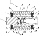
- Fig. 1 shows a bearing 1, comprising a core 2 and a surrounding shell 3 wherein the core 2 via at least one elastomer 4, 5 or more elastomers 4, 5 is supported against the shell 3, wherein between core 2 and shell 3 at least two a working fluid containing functional chambers 6 and 11 are formed and wherein the functional chambers 6 and 11 are at least partially limited by the one or more elastomers 4, 5.
- the at least two functional chambers 6 and 11 are fluid-conductively connected by a connecting channel 14.
- At least one compensating chamber 7 for a compensating fluid is provided, from which the compensating fluid can be introduced into the function chambers 6 and 11, wherein the compensating fluid in the compensating chamber 7 is separated from a gas-filled space 9 by a movable or elastic separating element 8.
- the compensation chamber 7 is fluidly connected by a channel 10 with a connecting channel 14 of the two functional chambers 6, 11. Within the channel 10, a check valve 15 is arranged.
- the flow restrictor 17 could comprise a web or web which is sandwiched between apertured disks.
- the compensation chamber 7 with a very thin channel 16 is fluid-conducting with the channel 10 and / or the connecting channel 14 and / or one or more functional chambers 6, 11, as in FIG Fig. 2 represented, fluidly connected.
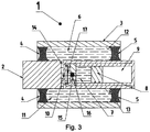
- Fig. 3 shows that the separating element 8 is designed as a movable piston.
- the separating element 8 could also be designed as a rolling diaphragm.
- two functional chambers 6, 11 are provided, which are both filled with working fluid.
- residual amounts of air 12, 13 are received, which arise during filling of the function chambers 6, 11 with working fluid.
- the pressure in the function chamber 6 can theoretically rise arbitrarily high, but in the functional chamber 11, in principle, do not fall below the vapor pressure of the working fluid. Due to high pressures in the storage system, the overall rigidity can be increased.
- a memory 20 is provided, which is tapped and replenished regularly. This could possibly be done by dynamic processes in the storage system itself. It could be a pressure reduction. An overpressure valve could be opened to the reservoir to increase the pressure again. With a pressure increase, a pressure relief valve could be provided to a further memory, in particular to the environment, which discharges pressure.
- a very large memory with a very large volume could provide a nearly constant pressure.
- a pressure reduction can just compensate for the stiffening of the elastomers when the temperature drops.
- a compensation of the modulus decrease of the elastomer at temperature increase is conceivable.
- the bearing could be used as a hydraulic bearing, in particular as a hydraulic armature bearing.
- the bearing could be used in rail vehicles as a hydraulic axle guide bearing.
- a residual amount of air in a functional chamber can be increased dramatically targeted.
- the parasitic effect of the amounts of residual air can be used as a means of characteristic design.
- Fig. 6 shows a bearing 1 in which the gas-filled space 9 is generally demarcated. This can be realized by a bellows, an elastic bladder or the like.
- Fig. 13 shows a bearing 1, comprising a core 2 and a surrounding shell 3 wherein the core 2 via at least one elastomer 4, 5 or more elastomers 4, 5 is supported against the shell 3, wherein between core 2 and shell 3 at least two a working fluid containing functional chambers 6 and 11 are formed and wherein the functional chambers 6 and 11 are at least partially limited by the one or more elastomers 4, 5.
- the at least two functional chambers 6 and 11 are fluid-conductively connected by a connecting channel 14.
- At least one compensating chamber 7 for a compensating fluid is provided, from which the compensating fluid can be introduced into the functional chambers (6, 11), wherein the compensating fluid in the compensating chamber 7 is separated from a plurality of gas-filled compartments by an elastic separating element 21.
- the separating element 21 is designed as a cellular rubber.
- the balance fluid is separated from many closed, gas-filled spaces, namely bubbles or cells, which are embedded in a rubber matrix.
Landscapes
- Engineering & Computer Science (AREA)
- General Engineering & Computer Science (AREA)
- Mechanical Engineering (AREA)
- Magnetic Bearings And Hydrostatic Bearings (AREA)
- Fluid-Damping Devices (AREA)
- Casting Or Compression Moulding Of Plastics Or The Like (AREA)
- Combined Devices Of Dampers And Springs (AREA)
Description
- Die Erfindung betrifft ein Lager nach dem Oberbegriff des Patentanspruchs 1.
- Aus dem Stand der Technik sind bereits Lager bekannt, welche einen Kern und eine diesen umgebende Hülle umfassen, siehe z.B.
WO0017047 DE10329982 ;WO2009046712 undJP2012172816 - Zwischen dem Kern und der Hülle sind eine oder mehrere Funktionskammern angeordnet, in denen Arbeitsfluide aufgenommen sind. Die Funktionskammern sind häufig an ihren axialen Enden durch die Elastomere begrenzt, welche den Kern an die Hülle anbinden.
- Solche Lager werden als hydraulische Lager bezeichnet und weisen üblicherweise zwei abgeschlossene und miteinander verbundene Funktionskammern auf, in denen jeweils ein Arbeitsfluid aufgenommen ist.
- Sobald ein hydraulisches Lager abgekühlt wird, entfalten unterschiedliche Ausdehnungskoeffizienten des Kerns, der Hülle sowie der Elastomere und des Arbeitsfluids ihre Wirkung.
- Das Arbeitsfluid in den Funktionskammern zeigt üblicherweise einen wesentlich höheren Ausdehnungskoeffizienten als die umgebenden, im Wesentlichen harten Begrenzungsmaterialien. Diese Begrenzungsmaterialien sind üblicherweise aus Metall oder Elastomeren gefertigt.
- Durch das Abkühlen des Arbeitsfluids entsteht in den Funktionskammern ein Hohlraum, bzw. ein Hohlvolumen, welches ausgeglichen werden muss. Die Bildung dieses Hohlvolumens führt zu einer Druckabsenkung im gesamten Lagersystem.
- Sofern Restluft in den Funktionskammern nach deren Füllen vorhanden ist, wird diese durch den sinkenden Druck ausgedehnt und sorgt für einen entsprechenden Volumenausgleich.
- Je mehr Restluft in den Funktionskammern aufgenommen ist, desto geringer ist der Druckabfall im Lager. Eine entstehende Luftblase ist aber immer im Wesentlichen so groß, wie der Volumenschwund des Arbeitsfluids.
- Vor diesem Hintergrund sei angemerkt, dass der Druck in den Funktionskammern unter den Dampfdruck des Arbeitsfluids sinkt, sofern keine Restluft in den Funktionskammern enthalten ist. Das Arbeitsfluid verdampft und füllt die entstandene Kavität bzw. das entstandene Hohlvolumen, der Systemdruck entspricht dann dem Dampfdruck des Arbeitsfluids.
- Das zuvor beschriebene Verhalten nimmt an Komplexität zu, wenn sehr unterschiedliche Mengen an Luft in den beiden Funktionskammern aufgenommen sind. Hierdurch ergeben sich asymmetrische Steifigkeitsverläufe.
- In jedem Fall muss bei einer Auslenkung des Kerns relativ zur Hülle, unabhängig von der Frequenz bzw. Geschwindigkeit der Auslenkung, zunächst ein entstandenes Hohlvolumen ausgeglichen werden, bevor ein signifikanter Druckanstieg in der Funktionskammer auftritt. Das Lager hat bis zu diesem Punkt nur die geringe Tragfedersteifigkeit, erst danach beginnt die höhere Blähfedersteifigkeit zu wirken.
- Der Erfindung liegt daher die Aufgabe zugrunde, ein Lager der eingangs genannten Art derart auszugestalten und weiter zu bilden, dass ein Steifigkeitseinbruch des Lagers bei niedrigen Temperaturen möglichst gering ausfällt. Das Dokument
WO 00/17047 - Erfindungsgemäß ist erkannt worden, dass ein Steifigkeitseinbruch bei niedrigen Temperaturen vermieden werden kann, indem das durch unterschiedliche Ausdehnungskoeffizienten auftretende Hohlvolumen durch ein Ausgleichsfluid ersetzt wird.
- Erfindungsgemäß ist konkret erkannt worden, dass dieses Ausgleichsfluid außerhalb der eigentlichen Funktionskammern gelagert werden muss. Durch die Zuführung des Ausgleichsfluids, um Hohlvolumina auszufüllen, kann verhindert werden, dass die Funktion der hydraulischen Versteifung bei hohen Frequenzen und/oder Geschwindigkeiten verloren geht.
- Erfindungsgemäß ist insbesondere erkannt worden, dass fertigungstechnisch stets eine gewisse Restluftmenge in den Funktionskammern verbleibt. Dabei ist erfindungsgemäß sichergestellt, dass der Druck innerhalb des Lagers nur um ein geringes Maß abfällt. Anderenfalls würde eine sich ausdehnende Restluftmenge zu Funktionseinschränkungen führen.
- Erfindungsgemäß wird all diesen Problemen durch eine Ausgleichskammer für ein Ausgleichsfluid begegnet, aus welcher das Ausgleichsfluid in eine Funktionskammer einleitbar ist. Dabei ist das Ausgleichsfluid in der Ausgleichskammer durch ein bewegliches oder elastisches Trennelement von einem gasgefüllten Raum getrennt. Durch das bewegliche oder elastische Trennelement ist die Menge des zugeführten Ausgleichsfluids problemlos dosierbar.
- Insoweit ist ein Lager derart ausgestaltet, dass ein Steifigkeitseinbruch des Lagers bei niedrigen Temperaturen möglichst gering ausfällt.
- Folglich ist die eingangs genannte Aufgabe gelöst.
- Die Ausgleichskammer könnte durch einen Kanal und ein Rückschlagventil mit einem Verbindungskanal der Funktionskammern fluidleitend verbindbar sein. Für die Funktionsfähigkeit des Lagers muss der Druck in der Ausgleichskammer so hoch sein, wie der statische Systemdruck, der sich im Stillstand des Lagers zwischen den Funktionskammern und dem Ausgleichsvolumen einstellt. Aus den Druckverläufen in den Funktionskammern bei dynamischer Belastung des Lagers lässt sich ermitteln, dass sich dieser statische Systemdruck als Minimalwert des Druckverlaufes in der Mitte des Verbindungskanals ergibt. Wird das Ausgleichsvolumen über ein Rückschlagventil derart mit der Mitte des Verbindungskanals verbunden, dass ein evtl. vorhandener Überdruck im Ausgleichsvolumen über dieses Rückschlagventil abgebaut wird, wenn das Druckminimum in der Mitte des Verbindungskanals erreicht wird, stellt sich im Ausgleichsvolumen besagter statischer Systemdruck des dynamisch nicht belasteten Lagers automatisch und ohne äußeren Eingriff ein.
- Die Ausgleichskammer könnte durch einen dünnen Kanal mit dem Verbindungskanal fluidleitend verbindbar sein. Ein steigender statischer Systemdruck in den Funktionskammern, z.B. durch Erwärmung des Lagers, kann über einen zusätzlichen Kanal zwischen dem Ausgleichsvolumen und dem Verbindungskanal oder einer der Funktionskammern ausgeglichen werden. Durch den Kanal, der sehr dünn ausgebildet ist, kann sehr dosiert bei jeder Druckspitze im Kanal oder in einer der Funktionskammern immer nur eine sehr geringe Menge an Fluid dem Ausgleichsvolumen zugeführt werden.
- Das Rückschlagventil könnte einen geringen Rückfluss in die Ausgleichskammer zulassen. Alternativ zu einem zusätzlichen dünnen Kanal kann auch das Rückschlagventil so ausgelegt werden, dass es bei Druckspitzen im Verbindungskanal einen sehr geringen Rückfluss in das Ausgleichsvolumen ermöglicht.
- Innerhalb des Kanals könnte eine Strömungsdrossel oder ein Filter angeordnet sein. Innerhalb des Kanals könnte eine Strömungsdrossel angeordnet sein. Vorzugsweise ist der Kanal so bemessen, dass bei funktionsrelevanten Frequenzen oder Geschwindigkeiten mit den im Lager herrschenden Drücken praktisch kein Volumenstrom zustande kommt und die volle dynamische Steifigkeit des Lagers zur Verfügung steht. Trotzdem soll der Kanal derart dimensioniert sein, dass ein Volumenausgleich bei Temperaturänderungen des gesamten Lagers, welcher sich über Minuten oder Stunden hinziehen kann, gewährleistet ist.
- Vor diesem Hintergrund könnte die Strömungsdrossel ein Vlies oder Gewebe aufweisen, welches zwischen zwei mit Durchgängen versehenen Scheiben sandwichartig aufgenommen ist. Hierdurch kann der Gefahr begegnet werden, dass Partikeln, die im Ausgleichsfluid schweben, den Kanal oder das Rückschlagventil zusetzen. Des Weiteren kann durch ein Gewebe oder Vlies ein Strömungswiderstand innerhalb des Kanals eingestellt werden.
- Der Strömungswiderstand kann durch eine Lage eines festen und dicht gepackten Vlieses oder Gewebes eingestellt werden. Das Vlies oder Gewebe wird gegen auftretende Druckunterschiede durch Scheiben mit Durchgängen gegen ein Verkippen oder gegen eine Auslenkung abgestützt.
- Der gasgefüllte Raum wird vorteilhaft so groß gewählt, dass ein Volumenausgleich ohne wesentlichen Druckabfall erfolgt. Die Größe des gasgefüllten Raums ist abhängig von der Restluftmenge in den Funktionskammern nach deren Befüllung, dem zu erwartenden Temperaturbereich, innerhalb dessen ausgeglichen werden muss, und einer zulässigen Abweichung von einer Kennlinie des Lagers. Vorzugsweise zeigt der gasgefüllte Raum etwa das Ein- bis Dreifache des Volumens, welches beim Abkühlen ausgeglichen werden muss.
- Das Trennelement könnte als beweglicher Kolben ausgestaltet sein. Die Trennung zwischen den Funktionskammern und Teilen der Ausgleichskammer muss gasdicht sein. Anderenfalls könnten unerwünschte Gase in die Funktionskammern gelangen. Vorzugsweise wird daher ein abgedichteter und axial beweglicher Kolben eingesetzt.
- Vor diesem Hintergrund ist auch denkbar, dass das Trennelement als Rollmembran ausgestaltet ist. Eine Rollmembran aus Elastomer, welche vorzugsweise mit einer Gewebeverstärkung versehen ist, zeichnet sich durch eine hohe Elastizität aus. Überdies ist eine Rollmembran aus einem Elastomer sehr leicht derart innerhalb eines Kanals verklemmbar, dass keine undichten Stellen entstehen.
- Das Trennelement könnte als Zellgummi ausgestaltet sein. Hierbei ist das Ausgleichsfluid von vielen abgeschlossenen, gasgefüllten Räumen, nämlich Blasen oder Zellen, abgetrennt, die in einer Gummimatrix eingebettet sind. Das Zellgummi bildet eine Knautschzone für eine bewegliche Ausgleichsfluidsäule.
- Auch Temperaturerhöhungen können erhebliche Auswirkungen auf die Eigenschaften eines Lagers haben. Durch eine Erwärmung des Arbeitsfluids können zusätzliche Volumina auftreten.
- Diese zusätzlichen Volumina führen zu einer Komprimierung der in den Funktionskammern üblicherweise aufgenommenen Restluft und zu einer Ausbeulung der Elastomere, welche den Kern gegen die Hülle abstützen.
- Hierdurch steigt der Druck im Lager bzw. in einem System, welches ein solches Lager aufweist. Durch eine Ausgleichskammer, in welcher ein Ausgleichsfluid vorgesehen ist, wobei das Ausgleichsfluid in der Ausgleichskammer durch ein bewegliches oder elastisches Trennelement von einem gasgefüllten Raum getrennt ist, können zusätzliche, durch Erwärmung entstehende Volumina kompensiert werden.
- Der durch die zusätzlichen Volumina entstehende zusätzliche Druck fördert Arbeitsfluid in die Ausgleichskammer hinein, wobei das Gas im gasgefüllten Raum komprimiert wird. Der Druckanstieg im Lager fällt daher wesentlich geringer aus. Das Arbeitsfluid und das Ausgleichsfluid sind vorzugsweise materialidentisch.
- In der Zeichnung zeigen
- Fig. 1
- ein Lager, welches eine Ausgleichskammer mit einem gasgefüllten Raum aufweist, wobei ein dünner Kanal in einem weiteren Kanal endet,
- Fig. 2
- ein Lager, welches eine Ausgleichskammer mit einem gasgefüllten Raum aufweist, wobei ein dünner Kanal in einer Funktionskammer endet,
- Fig. 3
- ein Lager, welches eine Ausgleichskammer mit einem gasgefüllten Raum aufweist, wobei eine Trennung von Fluid und Gas durch einen Trennkolben erfolgt,
- Fig. 4
- ein Lager, welches eine Ausgleichskammer mit einem gasgefüllten Raum aufweist und welches mit einem Ventil zur Befüllung/Steuerung des Drucks im gasgefüllten Raum der Ausgleichskammer ausgestattet ist,
- Fig. 5
- ein Lager, welches eine Ausgleichskammer mit einem gasgefüllten Raum aufweist und welches mit einem zusätzlichen großen externen Speicher ausgestattet ist, um das Volumen des gasgefüllten Raums zu erhöhen,
- Fig. 6
- ein Lager, in welchem ganz allgemein ein abgegrenzter, gasgefüllter Raum dargestellt ist,
- Fig. 7
- ein Diagramm, welches den Kraft-Weg-Verlauf eines Lagers mit geringen Mengen an Restluft bei Raumtemperatur zeigt,
- Fig. 8
- ein Diagramm, welches den Verlauf der Drücke in den Funktionskammern darstellt, wobei ein Verlauf bei Raumtemperatur, unbelastet 1 bar absolut, bei 2 mm Amplitude dargestellt ist,
- Fig. 9
- ein Diagramm, welches den Kraft-Weg-Verlauf eines Lagers mit geringen Mengen an Restluft in den Funktionskammern bei minus 20 °C zeigt,
- Fig. 10
- ein Diagramm, welches den Verlauf der Drücke in den Funktionskammern bei minus 20 °C, unbelastet 1 bar absolut, bei 2 mm Amplitude zeigt,
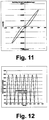
- Fig. 11
- ein Diagramm, welches den Kraft-Weg-Verlauf eines Lagers mit Ausgleichskammer bei minus 20 °C darstellt, wobei das Ausgleichsvolumen etwa den doppelten Temperaturschwund ausgleicht,
- Fig. 12
- ein Diagramm, welches den Verlauf der Drücke in den Funktionskammern bei minus 20 °C darstellt, wobei ein Ausgleichsvolumen der Ausgleichskammer etwa den doppelten Temperaturschwund kompensieren kann, und
- Fig. 13
- ein Lager, bei dem die Ausgleichskammer mit einem Zellgummi ausgestaltet ist.
-
Fig. 1 zeigt ein Lager 1, umfassend einen Kern 2 und eine diesen umgebende Hülle 3 wobei der Kern 2 über mindestens ein Elastomer 4, 5 oder mehrere Elastomere 4, 5 gegen die Hülle 3 abgestützt ist, wobei zwischen Kern 2 und Hülle 3 mindestens zwei ein Arbeitsfluid enthaltende Funktionskammern 6 und 11 ausgebildet sind und wobei die Funktionskammern 6 und 11 zumindest teilweise durch das oder die Elastomere 4, 5 begrenzt sind. Die mindestens zwei Funktionskammern 6 und 11 sind durch einen Verbindungskanal 14 fluidleitend verbunden. - Es ist mindestens eine Ausgleichskammer 7 für ein Ausgleichsfluid vorgesehen, aus welcher das Ausgleichsfluid in die Funktionskammern 6 und 11 einleitbar ist, wobei das Ausgleichsfluid in der Ausgleichskammer 7 durch ein bewegliches oder elastisches Trennelement 8 von einem gasgefüllten Raum 9 getrennt ist.
- Die Ausgleichskammer 7 ist durch einen Kanal 10 mit einem Verbindungskanal 14 der beiden Funktionskammern 6, 11 fluidleitend verbunden. Innerhalb des Kanals 10 ist ein Rückschlagventil 15 angeordnet.
- Innerhalb des Kanals 10 ist eine Strömungsdrossel 17 angeordnet. Die Strömungsdrossel 17 könnte ein Vlies oder Gewebe aufweisen, welches zwischen mit Durchgängen versehenen Scheiben sandwichartig aufgenommen ist.
- Zusätzlich ist die Ausgleichskammer 7 mit einem sehr dünnen Kanal 16 fluidleitend mit dem Kanal 10 und/ oder dem Verbindungskanal 14 und/ oder einer oder mehreren Funktionskammern 6, 11, wie in
Fig. 2 dargestellt, fluidleitend verbunden. -
Fig. 3 zeigt, dass das Trennelement 8 als beweglicher Kolben ausgestaltet ist. Das Trennelement 8 könnte auch als Rollmembran ausgestaltet sein. - In den konkret dargestellten Ausführungsbeispielen des Lagers 1 sind zwei Funktionskammern 6, 11 vorgesehen, welche beide mit Arbeitsfluid befüllt sind. In den Funktionskammern 6, 11 sind Restluftmengen 12, 13 aufgenommen, welche beim Befüllen der Funktionskammern 6, 11 mit Arbeitsfluid entstehen.
- Bei Belastung der Funktionskammern 6, 11 durch eine Bewegung in x-Richtung wird in der Funktionskammer 6 der Druck erhöht, in der Funktionskammer 11 der Druck abgesenkt. Dabei wirken beide Druckänderungen gleichsinnig als Gegenkraft zur Bewegungsrichtung x.
- Der Druck in der Funktionskammer 6 kann theoretisch beliebig hoch ansteigen, in der Funktionskammer 11 jedoch grundsätzlich nicht unter den Dampfdruck des Arbeitsfluides fallen. Durch hohe Vordrücke im Lagersystem kann die Gesamtsteifigkeit angehoben werden.
- Hierdurch ist es möglich, die dynamische Steifigkeit des Lagers 1 aktiv oder passiv durch die Regelung des Drucks über ein in
Fig. 4 gezeigtes Ventil 19 im gasgefüllten Raum 9 zu steuern. - Vor diesem Hintergrund sind viele passive Regelungen für einen Temperaturausgleich denkbar. Es könnte eine Bi-Metall-Feder verwendet werden, die auf einen Druckspeicher wirkt. Es könnten Ausdehnungskörper zur Kompensation von Volumenänderungen verwendet werden. Diese Ausdehnungskörper müssten negative Ausdehnungskoeffizienten zeigen.
- In
Fig. 5 ist ein Speicher 20 vorgesehen, der angezapft und regelmäßig aufgefüllt wird. Dies könnte eventuell durch dynamische Vorgänge im Lagersystem selbst erfolgen. Es könnte eine Drucksenkung erfolgen. Es könnte ein Überdruckventil zum Speicher hin geöffnet werden, um den Druck erneut anzuheben. Bei einer Druckerhöhung könnte ein Überdruckventil zu einem weiteren Speicher, insbesondere zur Umgebung, vorgesehen sein, welches Druck ablässt. - Bei einer rein passiven Ausgestaltung könnte ein sehr großer Speicher mit einem sehr großen Volumen für einen nahezu konstanten Druck sorgen. Bei geeigneter Auslegung des Volumens des großen Speichers relativ zu den Differenzvolumina in den Funktionskammern kann eine Druckabsenkung gerade die Versteifung der Elastomere bei Temperaturabsenkung ausgleichen. Ebenso ist eine Kompensation der Modulabnahme des Elastomers bei Temperaturerhöhung denkbar.
- Das Lager könnte als hydraulisches Lager, insbesondere als hydraulisches Achslenkerlager, verwendet werden. Das Lager könnte in Schienenfahrzeugen als hydraulisches Achslenkerlager verwendet werden.
- Es ist überdies möglich, Hydrolager mit einem bestimmten Vordruck auszustatten, um eine Kennlinie zu beeinflussen, ohne die Temperaturanfälligkeit zu erhöhen.
- Eine Restluftmenge in einer Funktionskammer kann gezielt dramatisch erhöht werden. So kann der parasitäre Effekt der Restluftmengen als Mittel zur Kennliniengestaltung genutzt werden.
-
Fig. 6 zeigt ein Lager 1 bei welchem der gasgefüllte Raum 9 ganz allgemein abgegrenzt ist. Dies kann durch einen Faltenbalg, eine elastische Blase oder ähnliches realisiert sein. -
Fig. 13 zeigt ein Lager 1, umfassend einen Kern 2 und eine diesen umgebende Hülle 3 wobei der Kern 2 über mindestens ein Elastomer 4, 5 oder mehrere Elastomere 4, 5 gegen die Hülle 3 abgestützt ist, wobei zwischen Kern 2 und Hülle 3 mindestens zwei ein Arbeitsfluid enthaltende Funktionskammern 6 und 11 ausgebildet sind und wobei die Funktionskammern 6 und 11 zumindest teilweise durch das oder die Elastomere 4, 5 begrenzt sind. Die mindestens zwei Funktionskammern 6 und 11 sind durch einen Verbindungskanal 14 fluidleitend verbunden. - Es ist mindestens eine Ausgleichskammer 7 für ein Ausgleichsfluid vorgesehen, aus welcher das Ausgleichsfluid in die Funktionskammern (6, 11) einleitbar ist, wobei das Ausgleichsfluid in der Ausgleichskammer 7 durch ein elastisches Trennelement 21 von mehreren gasgefüllten Räumen getrennt ist.
- Konkret ist das Trennelement 21 als Zellgummi ausgestaltet. Hier ist das Ausgleichsfluid von vielen abgeschlossenen, gasgefüllten Räumen, nämlich Blasen oder Zellen, abgetrennt, die in einer Gummimatrix eingebettet sind.
Claims (8)
- Lager (1), umfassend einen Kern (2) und eine diesen umgebende Hülle (3), wobei der Kern (2) über mindestens ein Elastomer (4, 5) oder mehrere Elastomere (4, 5) gegen die Hülle (3) abgestützt ist, wobei zwischen Kern (2) und Hülle (3) mindestens zwei ein Arbeitsfluid enthaltende Funktionskammern (6, 11) ausgebildet sind und wobei die Funktionskammern (6, 11) zumindest teilweise durch das oder die Elastomere (4, 5) begrenzt sind, wobei mindestens eine Ausgleichskammer (7) für ein Ausgleichsfluid vorgesehen ist, aus welcher das Ausgleichsfluid in die Funktionskammern (6, 11) einleitbar ist, wobei das Ausgleichsfluid in der Ausgleichskammer (7) durch ein bewegliches oder elastisches Trennelement (8, 21) von einem gasgefüllten Raum (9) oder mehreren gasgefüllten Räumen getrennt ist, dadurch gekennzeichnet, dass die Ausgleichskammer (7) durch einen Kanal (10) und ein Rückschlagventil (15) mit einem Verbindungskanal (14) der Funktionskammern (6, 11) fluidleitend verbindbar ist.
- Lager nach Anspruch 1, dadurch gekennzeichnet, dass die Ausgleichskammer (7) durch einen dünnen Kanal (16) mit dem Verbindungskanal (14) fluidleitend verbindbar ist.
- Lager nach Anspruch 1 oder 2, dadurch gekennzeichnet, dass das Rückschlagventil (15) einen geringen Rückfluss in die Ausgleichskammer (7) zulässt.
- Lager nach einem der Ansprüche 1 bis 3, dadurch gekennzeichnet, dass innerhalb des Kanals (10) eine Strömungsdrossel (17) oder ein Filter angeordnet ist.
- Lager nach Anspruch 4, dadurch gekennzeichnet, dass die Strömungsdrossel (17) ein Vlies oder Gewebe aufweist, welches zwischen mit Durchgängen versehenen Scheiben sandwichartig aufgenommen ist.
- Lager nach einem der Ansprüche 1 bis 5, dadurch gekennzeichnet, dass das Trennelement (8) als beweglicher Kolben ausgestaltet ist.
- Lager nach einem der Ansprüche 1 bis 5, dadurch gekennzeichnet, dass das Trennelement (8) als Rollmembran ausgestaltet ist.
- Lager nach einem der Ansprüche 1 bis 5, dadurch gekennzeichnet, dass das Trennelement (21) als Zellgummi ausgestaltet ist.
Applications Claiming Priority (3)
| Application Number | Priority Date | Filing Date | Title |
|---|---|---|---|
| DE102013005034 | 2013-03-25 | ||
| DE102013013092.1A DE102013013092A1 (de) | 2013-03-25 | 2013-08-07 | Lager |
| PCT/EP2014/000258 WO2014154315A1 (de) | 2013-03-25 | 2014-01-31 | Lager |
Publications (2)
| Publication Number | Publication Date |
|---|---|
| EP2978993A1 EP2978993A1 (de) | 2016-02-03 |
| EP2978993B1 true EP2978993B1 (de) | 2018-03-07 |
Family
ID=51484521
Family Applications (1)
| Application Number | Title | Priority Date | Filing Date |
|---|---|---|---|
| EP14705474.6A Active EP2978993B1 (de) | 2013-03-25 | 2014-01-31 | Lager |
Country Status (8)
| Country | Link |
|---|---|
| US (1) | US9797445B2 (de) |
| EP (1) | EP2978993B1 (de) |
| JP (1) | JP2016512876A (de) |
| CN (1) | CN105051406B (de) |
| CA (1) | CA2901784C (de) |
| DE (1) | DE102013013092A1 (de) |
| RU (1) | RU2633037C2 (de) |
| WO (1) | WO2014154315A1 (de) |
Cited By (1)
| Publication number | Priority date | Publication date | Assignee | Title |
|---|---|---|---|---|
| DE102020130271A1 (de) | 2020-11-17 | 2022-05-19 | Trelleborg Antivibration Solutions Germany Gmbh | Lager |
Families Citing this family (5)
| Publication number | Priority date | Publication date | Assignee | Title |
|---|---|---|---|---|
| EP3058245B1 (de) * | 2013-10-15 | 2020-05-06 | FM Energie GmbH & Co. KG | Elastische buchse für planetenlager |
| DE102015215426B4 (de) * | 2015-08-13 | 2019-06-19 | Schaeffler Technologies AG & Co. KG | Schaltbare Lagerbuchse für ein Kraftfahrzeug |
| DE102015215423A1 (de) * | 2015-08-13 | 2017-02-16 | Schaeffler Technologies AG & Co. KG | Schaltbare Lagerbuchse für ein Kraftfahrzeug |
| AT525672B1 (de) | 2022-02-02 | 2023-06-15 | Siemens Mobility Austria Gmbh | Fluidische Koppelvorrichtung und Fahrwerk |
| AT526283A1 (de) | 2022-06-28 | 2024-01-15 | Siemens Mobility Austria Gmbh | Fluidische Koppelvorrichtung und Fahrwerk |
Citations (1)
| Publication number | Priority date | Publication date | Assignee | Title |
|---|---|---|---|---|
| JP2012172816A (ja) * | 2011-02-24 | 2012-09-10 | Kyb Co Ltd | 緩衝器 |
Family Cites Families (20)
| Publication number | Priority date | Publication date | Assignee | Title |
|---|---|---|---|---|
| DE3940004A1 (de) | 1989-12-02 | 1991-06-06 | Freudenberg Carl Fa | Motorlager mit hydraulischer daempfung |
| US5374039A (en) * | 1992-08-24 | 1994-12-20 | Lord Corporation | Fluid-and-elastomer support device |
| US5501434A (en) | 1994-05-10 | 1996-03-26 | Lord Corporation | Hybrid fluid and elastomer damper |
| GB2304170A (en) * | 1995-08-08 | 1997-03-12 | Btr Antivibration Syst Inc | Fluid damping mount |
| JP3651144B2 (ja) * | 1996-10-25 | 2005-05-25 | 鹿島建設株式会社 | 制震用オイルダンパ |
| JP2000088036A (ja) | 1998-09-11 | 2000-03-28 | Maruyasu Industries Co Ltd | 防振支持装置 |
| US6045328A (en) * | 1998-09-23 | 2000-04-04 | Lord Corporation | Fluid damper including flexible damping plate |
| FR2806452B1 (fr) * | 2000-03-20 | 2002-05-03 | Hutchinson | Amortisseur de vibrations notamment pour rotor d'helicoptere |
| US6698731B2 (en) * | 2002-04-24 | 2004-03-02 | The Pullman Company | High compliance multiple chamber piston for fluid damped elastomer devices |
| JP2004068938A (ja) | 2002-08-07 | 2004-03-04 | Bridgestone Corp | 防振装置 |
| US20060071379A1 (en) | 2003-04-21 | 2006-04-06 | Akihiko Kato | Liquid-sealed vibration control device |
| DE10329982B4 (de) * | 2003-06-27 | 2005-09-15 | Siemens Ag | Vorrichtung zur Steuerung der Charakteristik eines Lagers mittels einer magnetisierbaren Flüssigkeit |
| DE10330877B4 (de) * | 2003-07-09 | 2019-11-07 | Contitech Vibration Control Gmbh | Fahrwerkslager |
| US20060151929A1 (en) | 2004-12-31 | 2006-07-13 | Randall Franck | Elastomeric/hydraulic vibration isolator with adjustable damping |
| JP2006308015A (ja) * | 2005-04-28 | 2006-11-09 | Fujikura Rubber Ltd | 防振ブッシュ |
| DE102005028563B4 (de) * | 2005-06-21 | 2021-06-10 | Contitech Vibration Control Gmbh | Lager |
| RU2312259C1 (ru) * | 2006-06-09 | 2007-12-10 | Олег Савельевич Кочетов | Гидравлическая виброизолирующая опора силового агрегата |
| DE102007048784B3 (de) | 2007-10-10 | 2009-04-23 | Zf Friedrichshafen Ag | Federbeinlager |
| DE102012001655A1 (de) | 2012-01-27 | 2013-08-01 | Audi Ag | Hydraulisch dämpfendes Lager für ein Fahrwerk eines Fahrzeuges, insbesondere eines Kraftfahrzeugs, sowie Verfahren zur Veränderung der Position eines Fahrwerklagers |
| CN102644693B (zh) * | 2012-05-11 | 2014-10-22 | 株洲时代新材料科技股份有限公司 | 一种带液体阻尼橡胶关节动刚度调节方法及橡胶关节 |
-
2013
- 2013-08-07 DE DE102013013092.1A patent/DE102013013092A1/de not_active Withdrawn
-
2014
- 2014-01-31 EP EP14705474.6A patent/EP2978993B1/de active Active
- 2014-01-31 CN CN201480017893.9A patent/CN105051406B/zh active Active
- 2014-01-31 WO PCT/EP2014/000258 patent/WO2014154315A1/de not_active Ceased
- 2014-01-31 RU RU2015145458A patent/RU2633037C2/ru active
- 2014-01-31 CA CA2901784A patent/CA2901784C/en active Active
- 2014-01-31 JP JP2016504505A patent/JP2016512876A/ja active Pending
- 2014-01-31 US US14/775,723 patent/US9797445B2/en active Active
Patent Citations (1)
| Publication number | Priority date | Publication date | Assignee | Title |
|---|---|---|---|---|
| JP2012172816A (ja) * | 2011-02-24 | 2012-09-10 | Kyb Co Ltd | 緩衝器 |
Cited By (2)
| Publication number | Priority date | Publication date | Assignee | Title |
|---|---|---|---|---|
| DE102020130271A1 (de) | 2020-11-17 | 2022-05-19 | Trelleborg Antivibration Solutions Germany Gmbh | Lager |
| EP4001692A1 (de) | 2020-11-17 | 2022-05-25 | Trelleborg Antivibration Solutions Germany GmbH | Lager |
Also Published As
| Publication number | Publication date |
|---|---|
| RU2633037C2 (ru) | 2017-10-11 |
| RU2015145458A (ru) | 2017-05-10 |
| WO2014154315A1 (de) | 2014-10-02 |
| US20160010686A1 (en) | 2016-01-14 |
| CA2901784C (en) | 2018-08-21 |
| DE102013013092A1 (de) | 2014-09-25 |
| CA2901784A1 (en) | 2014-10-02 |
| JP2016512876A (ja) | 2016-05-09 |
| EP2978993A1 (de) | 2016-02-03 |
| CN105051406A (zh) | 2015-11-11 |
| US9797445B2 (en) | 2017-10-24 |
| CN105051406B (zh) | 2018-01-02 |
Similar Documents
| Publication | Publication Date | Title |
|---|---|---|
| EP2978993B1 (de) | Lager | |
| EP3137320B1 (de) | Schwingungsdämpfer eines fahrzeug-rads | |
| EP2287492A1 (de) | Hydropneumatischer Kolbenspeicher | |
| EP2818751B1 (de) | Hydropneumatische Kolben-Zylinder-Anordnung | |
| DE102014111799B4 (de) | Fahrzeugaufhängungssystem und Fahrzeug mit einem solchen | |
| EP2253862A1 (de) | Dämpfungseinrichtung für Radfahrzeuge | |
| DE102013202802A1 (de) | Hydraulikeinheit | |
| WO2014019786A1 (de) | Hydraulisch dämpfendes buchsenlager | |
| DE10111551A1 (de) | Aktives Fahrwerksystem eines Fahrzeugs | |
| DE4101221A1 (de) | Hydropneumatisches federungssystem insbesondere fuer kfz-fahrerkabinen | |
| EP1709334A1 (de) | Druckspeicher, insbesondere pulsationsdämpfer | |
| EP2411696A1 (de) | Elastomeres buchsenlager mit schaltbarer steifigkeit | |
| DE102016201649B4 (de) | Selbstpumpendes hydropneumatisches Federbein | |
| DE102010012035B4 (de) | Federbein | |
| EP2481945B1 (de) | Federungseinrichtung für Fahrzeuge | |
| DE102017212882A1 (de) | Tragfeder-Dämpfer-System eines Fahrzeug-Rades | |
| EP2620302B1 (de) | Hydraulisch dämpfendes Lager für ein Fahrwerk eines Fahrzeuges, insbesondere eines Kraftfahrzeugs, sowie Verfahren zur Veränderung der Position eines Fahrwerklagers | |
| DE102010021029A1 (de) | Ausgleichselement für ein hydraulisches Wankstabilisatorsystem eines Kraftfahrzeugs | |
| EP2249057A1 (de) | Dämpfungseinrichtung für Radfahrzeuge | |
| DE102014005602A1 (de) | Lagerung eines Dämpfer- und/oder Federbeins an einem Fahrzeug | |
| WO2017050564A1 (de) | Schwingungsdämpfer sowie kraftfahrzeug | |
| WO2016113414A1 (de) | Dichtungssystem mit druckentlastungselementen und verwendung eines dichtungssystems zur einstellung einer zwischenraumdruckkaskade | |
| EP3329142B1 (de) | Hydraulischer einrohr-teleskop-schwingungsdämpfer | |
| DE202004005623U1 (de) | Federungs- und Dämpfungseinrichtung für Kraftfahrzeuge | |
| DE10243332A1 (de) | Stoßdämpfer |
Legal Events
| Date | Code | Title | Description |
|---|---|---|---|
| PUAI | Public reference made under article 153(3) epc to a published international application that has entered the european phase |
Free format text: ORIGINAL CODE: 0009012 |
|
| 17P | Request for examination filed |
Effective date: 20150827 |
|
| AK | Designated contracting states |
Kind code of ref document: A1 Designated state(s): AL AT BE BG CH CY CZ DE DK EE ES FI FR GB GR HR HU IE IS IT LI LT LU LV MC MK MT NL NO PL PT RO RS SE SI SK SM TR |
|
| AX | Request for extension of the european patent |
Extension state: BA ME |
|
| DAX | Request for extension of the european patent (deleted) | ||
| GRAP | Despatch of communication of intention to grant a patent |
Free format text: ORIGINAL CODE: EPIDOSNIGR1 |
|
| STAA | Information on the status of an ep patent application or granted ep patent |
Free format text: STATUS: GRANT OF PATENT IS INTENDED |
|
| INTG | Intention to grant announced |
Effective date: 20171016 |
|
| GRAS | Grant fee paid |
Free format text: ORIGINAL CODE: EPIDOSNIGR3 |
|
| GRAA | (expected) grant |
Free format text: ORIGINAL CODE: 0009210 |
|
| STAA | Information on the status of an ep patent application or granted ep patent |
Free format text: STATUS: THE PATENT HAS BEEN GRANTED |
|
| AK | Designated contracting states |
Kind code of ref document: B1 Designated state(s): AL AT BE BG CH CY CZ DE DK EE ES FI FR GB GR HR HU IE IS IT LI LT LU LV MC MK MT NL NO PL PT RO RS SE SI SK SM TR |
|
| REG | Reference to a national code |
Ref country code: GB Ref legal event code: FG4D Free format text: NOT ENGLISH |
|
| REG | Reference to a national code |
Ref country code: CH Ref legal event code: EP Ref country code: AT Ref legal event code: REF Ref document number: 976902 Country of ref document: AT Kind code of ref document: T Effective date: 20180315 |
|
| REG | Reference to a national code |
Ref country code: DE Ref legal event code: R096 Ref document number: 502014007527 Country of ref document: DE |
|
| REG | Reference to a national code |
Ref country code: IE Ref legal event code: FG4D Free format text: LANGUAGE OF EP DOCUMENT: GERMAN |
|
| REG | Reference to a national code |
Ref country code: SE Ref legal event code: TRGR |
|
| REG | Reference to a national code |
Ref country code: NL Ref legal event code: MP Effective date: 20180307 |
|
| REG | Reference to a national code |
Ref country code: LT Ref legal event code: MG4D |
|
| PG25 | Lapsed in a contracting state [announced via postgrant information from national office to epo] |
Ref country code: LT Free format text: LAPSE BECAUSE OF FAILURE TO SUBMIT A TRANSLATION OF THE DESCRIPTION OR TO PAY THE FEE WITHIN THE PRESCRIBED TIME-LIMIT Effective date: 20180307 Ref country code: HR Free format text: LAPSE BECAUSE OF FAILURE TO SUBMIT A TRANSLATION OF THE DESCRIPTION OR TO PAY THE FEE WITHIN THE PRESCRIBED TIME-LIMIT Effective date: 20180307 Ref country code: ES Free format text: LAPSE BECAUSE OF FAILURE TO SUBMIT A TRANSLATION OF THE DESCRIPTION OR TO PAY THE FEE WITHIN THE PRESCRIBED TIME-LIMIT Effective date: 20180307 Ref country code: CY Free format text: LAPSE BECAUSE OF FAILURE TO SUBMIT A TRANSLATION OF THE DESCRIPTION OR TO PAY THE FEE WITHIN THE PRESCRIBED TIME-LIMIT Effective date: 20180307 |
|
| REG | Reference to a national code |
Ref country code: NO Ref legal event code: T2 Effective date: 20180307 |
|
| PG25 | Lapsed in a contracting state [announced via postgrant information from national office to epo] |
Ref country code: BG Free format text: LAPSE BECAUSE OF FAILURE TO SUBMIT A TRANSLATION OF THE DESCRIPTION OR TO PAY THE FEE WITHIN THE PRESCRIBED TIME-LIMIT Effective date: 20180607 Ref country code: GR Free format text: LAPSE BECAUSE OF FAILURE TO SUBMIT A TRANSLATION OF THE DESCRIPTION OR TO PAY THE FEE WITHIN THE PRESCRIBED TIME-LIMIT Effective date: 20180608 Ref country code: LV Free format text: LAPSE BECAUSE OF FAILURE TO SUBMIT A TRANSLATION OF THE DESCRIPTION OR TO PAY THE FEE WITHIN THE PRESCRIBED TIME-LIMIT Effective date: 20180307 Ref country code: RS Free format text: LAPSE BECAUSE OF FAILURE TO SUBMIT A TRANSLATION OF THE DESCRIPTION OR TO PAY THE FEE WITHIN THE PRESCRIBED TIME-LIMIT Effective date: 20180307 |
|
| PG25 | Lapsed in a contracting state [announced via postgrant information from national office to epo] |
Ref country code: MT Free format text: LAPSE BECAUSE OF FAILURE TO SUBMIT A TRANSLATION OF THE DESCRIPTION OR TO PAY THE FEE WITHIN THE PRESCRIBED TIME-LIMIT Effective date: 20180307 |
|
| PG25 | Lapsed in a contracting state [announced via postgrant information from national office to epo] |
Ref country code: EE Free format text: LAPSE BECAUSE OF FAILURE TO SUBMIT A TRANSLATION OF THE DESCRIPTION OR TO PAY THE FEE WITHIN THE PRESCRIBED TIME-LIMIT Effective date: 20180307 Ref country code: AL Free format text: LAPSE BECAUSE OF FAILURE TO SUBMIT A TRANSLATION OF THE DESCRIPTION OR TO PAY THE FEE WITHIN THE PRESCRIBED TIME-LIMIT Effective date: 20180307 Ref country code: NL Free format text: LAPSE BECAUSE OF FAILURE TO SUBMIT A TRANSLATION OF THE DESCRIPTION OR TO PAY THE FEE WITHIN THE PRESCRIBED TIME-LIMIT Effective date: 20180307 Ref country code: RO Free format text: LAPSE BECAUSE OF FAILURE TO SUBMIT A TRANSLATION OF THE DESCRIPTION OR TO PAY THE FEE WITHIN THE PRESCRIBED TIME-LIMIT Effective date: 20180307 Ref country code: PL Free format text: LAPSE BECAUSE OF FAILURE TO SUBMIT A TRANSLATION OF THE DESCRIPTION OR TO PAY THE FEE WITHIN THE PRESCRIBED TIME-LIMIT Effective date: 20180307 |
|
| PG25 | Lapsed in a contracting state [announced via postgrant information from national office to epo] |
Ref country code: CZ Free format text: LAPSE BECAUSE OF FAILURE TO SUBMIT A TRANSLATION OF THE DESCRIPTION OR TO PAY THE FEE WITHIN THE PRESCRIBED TIME-LIMIT Effective date: 20180307 Ref country code: SK Free format text: LAPSE BECAUSE OF FAILURE TO SUBMIT A TRANSLATION OF THE DESCRIPTION OR TO PAY THE FEE WITHIN THE PRESCRIBED TIME-LIMIT Effective date: 20180307 Ref country code: SM Free format text: LAPSE BECAUSE OF FAILURE TO SUBMIT A TRANSLATION OF THE DESCRIPTION OR TO PAY THE FEE WITHIN THE PRESCRIBED TIME-LIMIT Effective date: 20180307 |
|
| REG | Reference to a national code |
Ref country code: DE Ref legal event code: R097 Ref document number: 502014007527 Country of ref document: DE |
|
| PG25 | Lapsed in a contracting state [announced via postgrant information from national office to epo] |
Ref country code: PT Free format text: LAPSE BECAUSE OF FAILURE TO SUBMIT A TRANSLATION OF THE DESCRIPTION OR TO PAY THE FEE WITHIN THE PRESCRIBED TIME-LIMIT Effective date: 20180709 |
|
| PLBE | No opposition filed within time limit |
Free format text: ORIGINAL CODE: 0009261 |
|
| STAA | Information on the status of an ep patent application or granted ep patent |
Free format text: STATUS: NO OPPOSITION FILED WITHIN TIME LIMIT |
|
| PG25 | Lapsed in a contracting state [announced via postgrant information from national office to epo] |
Ref country code: DK Free format text: LAPSE BECAUSE OF FAILURE TO SUBMIT A TRANSLATION OF THE DESCRIPTION OR TO PAY THE FEE WITHIN THE PRESCRIBED TIME-LIMIT Effective date: 20180307 |
|
| 26N | No opposition filed |
Effective date: 20181210 |
|
| PG25 | Lapsed in a contracting state [announced via postgrant information from national office to epo] |
Ref country code: IT Free format text: LAPSE BECAUSE OF FAILURE TO SUBMIT A TRANSLATION OF THE DESCRIPTION OR TO PAY THE FEE WITHIN THE PRESCRIBED TIME-LIMIT Effective date: 20180307 Ref country code: SI Free format text: LAPSE BECAUSE OF FAILURE TO SUBMIT A TRANSLATION OF THE DESCRIPTION OR TO PAY THE FEE WITHIN THE PRESCRIBED TIME-LIMIT Effective date: 20180307 |
|
| PG25 | Lapsed in a contracting state [announced via postgrant information from national office to epo] |
Ref country code: MC Free format text: LAPSE BECAUSE OF FAILURE TO SUBMIT A TRANSLATION OF THE DESCRIPTION OR TO PAY THE FEE WITHIN THE PRESCRIBED TIME-LIMIT Effective date: 20180307 |
|
| PG25 | Lapsed in a contracting state [announced via postgrant information from national office to epo] |
Ref country code: LU Free format text: LAPSE BECAUSE OF NON-PAYMENT OF DUE FEES Effective date: 20190131 |
|
| REG | Reference to a national code |
Ref country code: BE Ref legal event code: MM Effective date: 20190131 |
|
| REG | Reference to a national code |
Ref country code: IE Ref legal event code: MM4A |
|
| REG | Reference to a national code |
Ref country code: DE Ref legal event code: R082 Ref document number: 502014007527 Country of ref document: DE Representative=s name: REISER & PARTNER PATENTANWAELTE MBB, DE Ref country code: DE Ref legal event code: R081 Ref document number: 502014007527 Country of ref document: DE Owner name: TRELLEBORG ANTIVIBRATION SOLUTIONS GERMANY GMB, DE Free format text: FORMER OWNER: CARL FREUDENBERG KG, 69469 WEINHEIM, DE |
|
| PG25 | Lapsed in a contracting state [announced via postgrant information from national office to epo] |
Ref country code: BE Free format text: LAPSE BECAUSE OF NON-PAYMENT OF DUE FEES Effective date: 20190131 |
|
| PG25 | Lapsed in a contracting state [announced via postgrant information from national office to epo] |
Ref country code: IE Free format text: LAPSE BECAUSE OF NON-PAYMENT OF DUE FEES Effective date: 20190131 |
|
| PG25 | Lapsed in a contracting state [announced via postgrant information from national office to epo] |
Ref country code: TR Free format text: LAPSE BECAUSE OF FAILURE TO SUBMIT A TRANSLATION OF THE DESCRIPTION OR TO PAY THE FEE WITHIN THE PRESCRIBED TIME-LIMIT Effective date: 20180307 |
|
| REG | Reference to a national code |
Ref country code: NO Ref legal event code: CHAD Owner name: TRELLEBORG ANTIVIBRATION SOLUTIONS GERMANY G, DE |
|
| REG | Reference to a national code |
Ref country code: GB Ref legal event code: 732E Free format text: REGISTERED BETWEEN 20200723 AND 20200729 Ref country code: FI Ref legal event code: PCE Owner name: TRELLEBORG ANTIVIBRATION SOLUTIONS GERMANY GMBH |
|
| PG25 | Lapsed in a contracting state [announced via postgrant information from national office to epo] |
Ref country code: IS Free format text: LAPSE BECAUSE OF FAILURE TO SUBMIT A TRANSLATION OF THE DESCRIPTION OR TO PAY THE FEE WITHIN THE PRESCRIBED TIME-LIMIT Effective date: 20180707 |
|
| PG25 | Lapsed in a contracting state [announced via postgrant information from national office to epo] |
Ref country code: HU Free format text: LAPSE BECAUSE OF FAILURE TO SUBMIT A TRANSLATION OF THE DESCRIPTION OR TO PAY THE FEE WITHIN THE PRESCRIBED TIME-LIMIT; INVALID AB INITIO Effective date: 20140131 |
|
| REG | Reference to a national code |
Ref country code: AT Ref legal event code: PC Ref document number: 976902 Country of ref document: AT Kind code of ref document: T Owner name: TRELLEBORG ANTIVIBRATION SOLUTIONS GERMANY GMB, DE Effective date: 20220421 |
|
| PG25 | Lapsed in a contracting state [announced via postgrant information from national office to epo] |
Ref country code: MK Free format text: LAPSE BECAUSE OF FAILURE TO SUBMIT A TRANSLATION OF THE DESCRIPTION OR TO PAY THE FEE WITHIN THE PRESCRIBED TIME-LIMIT Effective date: 20180307 |
|
| REG | Reference to a national code |
Ref country code: CH Ref legal event code: U11 Free format text: ST27 STATUS EVENT CODE: U-0-0-U10-U11 (AS PROVIDED BY THE NATIONAL OFFICE) Effective date: 20260201 |
|
| PGFP | Annual fee paid to national office [announced via postgrant information from national office to epo] |
Ref country code: SE Payment date: 20260121 Year of fee payment: 13 |
|
| PGFP | Annual fee paid to national office [announced via postgrant information from national office to epo] |
Ref country code: GB Payment date: 20260122 Year of fee payment: 13 |
|
| PGFP | Annual fee paid to national office [announced via postgrant information from national office to epo] |
Ref country code: NO Payment date: 20260120 Year of fee payment: 13 Ref country code: DE Payment date: 20260120 Year of fee payment: 13 |
|
| PGFP | Annual fee paid to national office [announced via postgrant information from national office to epo] |
Ref country code: AT Payment date: 20260119 Year of fee payment: 13 |
|
| PGFP | Annual fee paid to national office [announced via postgrant information from national office to epo] |
Ref country code: FI Payment date: 20260120 Year of fee payment: 13 |
|
| PGFP | Annual fee paid to national office [announced via postgrant information from national office to epo] |
Ref country code: FR Payment date: 20260128 Year of fee payment: 13 |
|
| PGFP | Annual fee paid to national office [announced via postgrant information from national office to epo] |
Ref country code: CH Payment date: 20260201 Year of fee payment: 13 |