EP2979929A1 - An adjustable multi-use windshield bracket - Google Patents
An adjustable multi-use windshield bracket Download PDFInfo
- Publication number
- EP2979929A1 EP2979929A1 EP14465517.2A EP14465517A EP2979929A1 EP 2979929 A1 EP2979929 A1 EP 2979929A1 EP 14465517 A EP14465517 A EP 14465517A EP 2979929 A1 EP2979929 A1 EP 2979929A1
- Authority
- EP
- European Patent Office
- Prior art keywords
- bracket
- windshield
- bracket component
- inclination angle
- components
- Prior art date
- Legal status (The legal status is an assumption and is not a legal conclusion. Google has not performed a legal analysis and makes no representation as to the accuracy of the status listed.)
- Granted
Links
Images


Classifications
-
- B—PERFORMING OPERATIONS; TRANSPORTING
- B60—VEHICLES IN GENERAL
- B60R—VEHICLES, VEHICLE FITTINGS, OR VEHICLE PARTS, NOT OTHERWISE PROVIDED FOR
- B60R11/00—Arrangements for holding or mounting articles, not otherwise provided for
-
- B—PERFORMING OPERATIONS; TRANSPORTING
- B60—VEHICLES IN GENERAL
- B60R—VEHICLES, VEHICLE FITTINGS, OR VEHICLE PARTS, NOT OTHERWISE PROVIDED FOR
- B60R11/00—Arrangements for holding or mounting articles, not otherwise provided for
- B60R2011/0001—Arrangements for holding or mounting articles, not otherwise provided for characterised by position
- B60R2011/0003—Arrangements for holding or mounting articles, not otherwise provided for characterised by position inside the vehicle
- B60R2011/0026—Windows, e.g. windscreen
-
- G—PHYSICS
- G01—MEASURING; TESTING
- G01S—RADIO DIRECTION-FINDING; RADIO NAVIGATION; DETERMINING DISTANCE OR VELOCITY BY USE OF RADIO WAVES; LOCATING OR PRESENCE-DETECTING BY USE OF THE REFLECTION OR RERADIATION OF RADIO WAVES; ANALOGOUS ARRANGEMENTS USING OTHER WAVES
- G01S13/00—Systems using the reflection or reradiation of radio waves, e.g. radar systems; Analogous systems using reflection or reradiation of waves whose nature or wavelength is irrelevant or unspecified
- G01S13/88—Radar or analogous systems specially adapted for specific applications
- G01S13/93—Radar or analogous systems specially adapted for specific applications for anti-collision purposes
- G01S13/931—Radar or analogous systems specially adapted for specific applications for anti-collision purposes of land vehicles
- G01S2013/9327—Sensor installation details
- G01S2013/93276—Sensor installation details in the windshield area
Definitions
- the invention relates to an adjustable multi-use windshield bracket for mounting electronic and/or mechanical components onto a windshield of a vehicle.
- Windshield brackets are mechanical interfacing components used in the automotive industry to mount different electronic and/or mechanical components such as sensor devices on the windshield of a vehicle.
- the design of the windshield brackets is dictated by the shape, position and orientation of the windshield they are mounted on, as well as the particular requirements of the components received by the windshield brackets. These design requirements are often in conflict with each other. Accordingly, it has been necessary to provide a bracket with different design for each carline. The reason for this is that the different windshield orientation with respect to the average ground plane requires a different mounting angle of the sensor device received by the bracket with respect to the windshield of the vehicle, in particular if the sensor device does not have any software angle adjustment options. Even if such a software angle correction is available, some extreme windshield angles can still cause performance degradation of the sensor device.
- an adjustable multi-use windshield bracket comprising the features of claim 1.
- an adjustable multi-use windshield bracket for mounting electronic and/or mechanical components onto a windshield of a vehicle, said adjustable multi-use windshield bracket comprising:
- the first bracket component is a fixed bracket component placed on a flat surface for adjusting the inclination angle between the fixed bracket component and the rotating mobile second bracket component to a predetermined set inclination angle corresponding to the inclination angle of the windshield.
- the inclination angle between the fixed bracket component and the rotating mobile second bracket component is adjustable by means of an inserted rectified stand limiting the rotation of the mobile second bracket component towards the flat surface.
- the rectified stand is inserted between the mobile second bracket component and the flat surface and comprises a height defining the desired set inclination angle.
- the snap-in rotational coupling between the first fixed bracket component and the second mobile bracket component comprises at the fixed bracket component a half cylindrical support surface with a predetermined radius and a snapper having a half cylindrical retaining surface and comprises at the mobile bracket component a complimentary half cylindrical support surface with the same predetermined radius and a half cylindrical pocket adapted to receive the snapper of the fixed bracket component.
- the snapper of the fixed bracket component has a half cylindrical retaining surface which is marginally smaller than the radius of the half cylindrical pocket of the second mobile bracket component to allow a preassembly of both bracket components.
- both bracket components are joined permanently with the set inclination angle by welding, gluing or bonding both bracket components together.
- the rectified stand with its predetermined height is selected from a group of available rectified stands corresponding to windshields with different inclination angles of the same or different carlines.
- the invention further provides according to a second aspect a method for manufacturing a multi-use windshield bracket of a vehicle comprising the features of claim 9.
- the invention provides according to the second aspect of the present invention a method for manufacturing a multi-use windshield bracket of a vehicle comprising the steps of: preassembling the multi-use windshield bracket by snapping a first bracket component into a second bracket component by means of a mechanical snap-in rotational coupling; placing the first bracket component of the preassembled multi-use windshield bracket on a flat surface and rotating the mobile second bracket component around a rotational axis of said snap-in rotating coupling until it abuts on an inserted rectified stand of predetermined height defining a desired set inclination angle; and joining both bracket components together with the set inclination angle.
- both bracket components are joined permanently together after having set the inclination angle by welding, gluing or bonding both bracket components together.
- the inserted rectified stand comprises a height defining a desired set inclination angle and is selected from a group of available rectified stands corresponding to windshields of different types used in the same or different carlines.
- the invention further provides a vehicle comprising a driver assistance system with electronic sensor devices mounted to a windshield of said vehicle by a multi-use bracket having the features of claim 12.
- the invention provides according to a third aspect of the present invention a vehicle comprising a driver assistance system with electronic sensor devices mounted to a windshield of said vehicle by a multi-use bracket, wherein the adjustable multi-use windshield bracket comprises a first bracket component connected to a second bracket component by a snap-in rotational coupling allowing a relative rotation between both bracket components around a rotation axis to set an inclination angle fixed by joining both bracket components with the set inclination angle.
- the multi-use bracket comprises a set inclination angle corresponding to the inclination angle of the windshield of said vehicle.
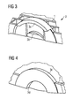
- Figures 3, 4 , 5, 6 illustrate a possible exemplary embodiment of a snap-in rotational coupling 3 used for connecting the fixed and mobile bracket components 1, 2 of the adjustable multi-use windshield bracket.
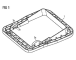
- Figure 3 shows the snap-in rotational coupling 3 provided at the fixed bracket component 1 illustrated in Figure 1 .
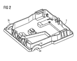
- Figure 4 shows the snap-in rotational coupling 3 at the mobile bracket component 2 illustrated in Figure 2 .
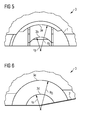
- the snap-in rotational coupling 3 between the first fixed bracket component 1 and the second mobile bracket component 2 comprises at the fixed bracket component 1 a half cylindrical support surface 3a with a predetermined radius R s and a snapper 3b having a half cylindrical retaining surface with a radius r R as also illustrated in the diagram of Figure 5 .
- the snap-in rotational coupling 3 comprises at the mobile bracket component 2 as illustrated in Figure 2 a complementary half cylindrical support surface 3c with the same predetermined radius R s as the half cylindrical support surface 3a and a half cylindrical pocket 3d adapted to receive the snapper 3b at the fixed bracket component 1.
- the snapper 3b of the fixed bracket component 1 has a half cylindrical retaining surface which is marginally smaller than the radius of the half cylindrical pocket 3d of the second mobile bracket component 2 to allow a preassembly of both bracket components 1, 2.
- the mobile bracket component 2 shown in Figure 2 can be inserted into the fixed bracket component 1 illustrated in Figure 1 from below.
- FIGs of Figures 8, 9 illustrate connecting the rotational coupling between the two bracket components 1, 2 for preassembling the multi-use windshield bracket.
- the inside support surface 3a of the fixed bracket component 1 with the outside support surface 3c of the mobile bracket component 2 are complementary constituting a sliding contact surface between the two bracket components 1, 2.
- the retaining surface of the snapper 3b of the fixed bracket component 1 with the surface 3d of the pocket of the mobile bracket component 2 are also complementary holding both bracket components 1, 2 in place.
- the snapper 3b from the fixed bracket component 1 bends and allows the mobile bracket component 2 to snap into the final position as shown in Figure 9 .
- the two bracket components are preassembled, i.e. the bracket components 1, 2 are held together, but there is still a rotation around a rotation axis possible.
- the snap-in rotational coupling 3 takes away five degrees of freedom from the assembly leaving one degree of motion freedom, i.e. rotation around the rotation axis of the snap-in rotational coupling 3.
- the inclination angle can be set between the two bracket components 1, 2 eliminating the last degree of motion freedom.
- this is done by placing the preassembled multi-use windshield bracket as illustrated in Figure 10 on a rectified plate 4, having a flat surface.
- the fixed bracket component 1 is in contact with the flat surface.
- the mobile bracket component 2 is still able to rotate freely around the rotation axis of the snap-in rotational coupling 3.
- a rectified stand 5 of a predetermined height is inserted to define a desired set inclination angle.
- the mobile second bracket component 2 is rotated around the rotation axis of the snap-in rotational coupling 3 until it abuts on the inserted rectified stand 5 to define the desired set inclination angle.
- the rectified stand 5 limits the rotation in the downward direction as illustrated in Figure 11 .
- the rectified stand 5 has the precise height that limits the rotation of the mobile bracket component 2 so that in the contact position between this rectified stand 5 and the mobile bracket component 2 the angle between the two bracket component halves is at precisely the desired angle value.
- the next step of the assembly process is fixing the set angle. This is illustrated in Figure 12 .
- both bracket components 1, 2 can be joined together with the set inclination angle.
- both bracket components 1, 2 are joined permanently together after having set the inclination angle by welding, gluing or bonding both bracket components 1, 2 together.
- a permanent fixing PF is illustrated in Figure 12 as a dashed line.
- the permanent fixing PF is performed between the fixed and mobile bracket components in the back side area of the bracket for a better stability and resistance.
- the options include but are not limited to laser welding, ultrasonic welding, gluing or electromagnetic resin bonding.
- the adjustable multi-use windshield brackets can then be fixed or attached to the windshield of the vehicle.
- the adjustable multi-use windshield bracket with the set inclination angle is connected to a flexible supporting bracket of a modular bracket assembly before being attached to the curved windshield of the vehicle.
- the inserted rectified stand 5 as illustrated in Figure 11 is selected from a group of available rectified stands corresponding to windshields of different types used in the same or different carlines.
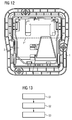
- Figure 13 shows a flow chart for illustrating an exemplary embodiment of a method for manufacturing a multi-use windshield bracket of a vehicle according to the second aspect of the present invention.
- a first step S1 the multi-use windshield bracket is preassembled by snapping a first bracket component 1 into a second bracket component 2 by means of a mechanical snap-in rotational coupling 3.
- a second step S2 the first bracket component 1 of the preassembled multi-use windshield bracket is placed on a flat surface and the mobile second bracket component 2 is rotated around a rotational axis of the snap-in rotating coupling 3 until it abuts on an inserted rectified stand 5 of a predetermined height defining a desired set inclination angle.
- both bracket components 1, 2 are joined together with the set inclination angle.
- the multi-use windshield bracket can be connected by a connecting plate of a multi-bracket assembly with other brackets.
- the connecting plate of this multi-bracket assembly can be made of a flexible material to allow mounting of the different brackets including the adjustable multi-use windshield bracket according to the present invention to a curved surface, in particular to a curved windshield.
- the complete assembly can be fixed or attached to the windshield or another curved surface of the vehicle, for instance by gluing.
- the manufactured multi-use windshield bracket according to the present invention as illustrated in Figure 12 can be used to receive mechanical, electronic or electromechanical components, in particular sensor devices of a driver assistance system of a vehicle.
- the adjustable multi-use windshield bracket can be used to receive an optical sensor device mounted on a windshield of the vehicle.
- An advantage of the adjustable multi-use windshield bracket according to the present invention is that it does not require additional mechanical components like nuts and bolts.
- the snap-in rotational coupling 3 is used both to provide the relative rotation support and to fix the relative position of the two bracket halves.
- the final step of fixing the angle is comparatively fast and simple, unlike using nuts and bolts or screws, as no extra components are required and one does not need a precise control of the torque of the nut, bolt or screw to prevent part damaging or having insufficient mechanical force available.
- the adjustable multi-use windshield bracket can be used for any sensor devices and sensor angle requirements on all carlines. With the method according to the present invention, only one assembly jig including the rectified surface and the rectified stand 5 is needed per carline, and all brackets can be made and assembled very fast with minimal risks.
Landscapes
- Engineering & Computer Science (AREA)
- Mechanical Engineering (AREA)
- Fittings On The Vehicle Exterior For Carrying Loads, And Devices For Holding Or Mounting Articles (AREA)
Abstract
Description
- The invention relates to an adjustable multi-use windshield bracket for mounting electronic and/or mechanical components onto a windshield of a vehicle.
- Windshield brackets are mechanical interfacing components used in the automotive industry to mount different electronic and/or mechanical components such as sensor devices on the windshield of a vehicle. The design of the windshield brackets is dictated by the shape, position and orientation of the windshield they are mounted on, as well as the particular requirements of the components received by the windshield brackets. These design requirements are often in conflict with each other. Accordingly, it has been necessary to provide a bracket with different design for each carline. The reason for this is that the different windshield orientation with respect to the average ground plane requires a different mounting angle of the sensor device received by the bracket with respect to the windshield of the vehicle, in particular if the sensor device does not have any software angle adjustment options. Even if such a software angle correction is available, some extreme windshield angles can still cause performance degradation of the sensor device. An additional issue is the unpredictability of the production process for producing windshields. From the nominal design of the windshield, it is not possible to accurately predict the final real shape of the windshield. A consequence of this is that in the area where the sensor devices are mounted, it is impossible to predict the pitch angle deviations that can affect the performance of the sensor devices negatively. The most common way of dealing with these different requirements from carline to carline is to just have a different bracket interface built for each carline. To avoid the production of a different part every time, another option is to have a single adjustable bracket interface. However, solutions up until now are formed by relatively complicated mechanical systems using pairs of nuts and bolts to provide a hinge and an angle fixing solution or a flexible beam system that can change shape to reorient the sensor device to the windshield.
- Accordingly, it is an object of the present invention to provide a method and apparatus to mount electronic and/or mechanical components onto a windshield of a vehicle which can be used for windshields with different inclination angles used in different carlines.
- This object is achieved by an adjustable multi-use windshield bracket comprising the features of
claim 1. - Accordingly, the invention provides according to a first aspect an adjustable multi-use windshield bracket for mounting electronic and/or mechanical components onto a windshield of a vehicle,
said adjustable multi-use windshield bracket comprising: - a first bracket component connected to a second bracket component by a snap-in rotational coupling allowing a relative rotation between both bracket components around a rotation axis to set an inclination angle fixed by joining both bracket components with the set inclination angle.
- According to a possible embodiment of the adjustable multi-use windshield bracket according to the first aspect of the present invention, the first bracket component is a fixed bracket component placed on a flat surface for adjusting the inclination angle between the fixed bracket component and the rotating mobile second bracket component to a predetermined set inclination angle corresponding to the inclination angle of the windshield.
- In a further possible embodiment of the adjustable multi-use windshield bracket according to the first aspect of the present invention, the inclination angle between the fixed bracket component and the rotating mobile second bracket component is adjustable by means of an inserted rectified stand limiting the rotation of the mobile second bracket component towards the flat surface.
- In a still further possible embodiment of the adjustable multi-use windshield bracket according to the first aspect of the present invention, the rectified stand is inserted between the mobile second bracket component and the flat surface and comprises a height defining the desired set inclination angle.
- In a still further possible embodiment of the adjustable multi-use windshield bracket according to the first aspect of the present invention, the snap-in rotational coupling between the first fixed bracket component and the second mobile bracket component comprises at the fixed bracket component a half cylindrical support surface with a predetermined radius and a snapper having a half cylindrical retaining surface and comprises at the mobile bracket component a complimentary half cylindrical support surface with the same predetermined radius and a half cylindrical pocket adapted to receive the snapper of the fixed bracket component.
- In a still further possible embodiment of the adjustable multi-use windshield bracket according to the first aspect of the present invention, the snapper of the fixed bracket component has a half cylindrical retaining surface which is marginally smaller than the radius of the half cylindrical pocket of the second mobile bracket component to allow a preassembly of both bracket components.
- In a still further possible embodiment of the adjustable multi-use windshield bracket according to the first aspect of the present invention, both bracket components are joined permanently with the set inclination angle by welding, gluing or bonding both bracket components together.
- In a still further possible embodiment of the adjustable multi-use windshield bracket according to the first aspect of the present invention, the rectified stand with its predetermined height is selected from a group of available rectified stands corresponding to windshields with different inclination angles of the same or different carlines.
- The invention further provides according to a second aspect a method for manufacturing a multi-use windshield bracket of a vehicle comprising the features of claim 9.
- The invention provides according to the second aspect of the present invention a method for manufacturing a multi-use windshield bracket of a vehicle comprising the steps of: preassembling the multi-use windshield bracket by snapping a first bracket component into a second bracket component by means of a mechanical snap-in rotational coupling; placing the first bracket component of the preassembled multi-use windshield bracket on a flat surface and rotating the mobile second bracket component around a rotational axis of said snap-in rotating coupling until it abuts on an inserted rectified stand of predetermined height defining a desired set inclination angle; and
joining both bracket components together with the set inclination angle. - In a possible embodiment of the method according to the second aspect of the present invention, both bracket components are joined permanently together after having set the inclination angle by welding, gluing or bonding both bracket components together.
- In a further possible embodiment of the method according to the second aspect of the present invention, the inserted rectified stand comprises a height defining a desired set inclination angle and is selected from a group of available rectified stands corresponding to windshields of different types used in the same or different carlines.
- The invention further provides a vehicle comprising a driver assistance system with electronic sensor devices mounted to a windshield of said vehicle by a multi-use bracket having the features of claim 12.
- The invention provides according to a third aspect of the present invention a vehicle comprising a driver assistance system with electronic sensor devices mounted to a windshield of said vehicle by a multi-use bracket, wherein the adjustable multi-use windshield bracket comprises a first bracket component connected to a second bracket component by a snap-in rotational coupling allowing a relative rotation between both bracket components around a rotation axis to set an inclination angle fixed by joining both bracket components with the set inclination angle.
- In a possible embodiment of the vehicle according to the third aspect of the present invention, the multi-use bracket comprises a set inclination angle corresponding to the inclination angle of the windshield of said vehicle.
- In the following, possible embodiments of the different aspects of the present invention are described with reference to the enclosed figures in more detail.
- Figure 1
- shows a perspective view on an exemplary embodiment of a fixed bracket component used in an adjustable multi-use windshield bracket according to the first aspect of the present invention;
- Figure 2
- shows a perspective view on a mobile bracket component as used in an adjustable multi-use windshield bracket according to the first aspect of the present invention;
- Figure 3
- shows an exemplary snap-in rotational coupling at the fixed bracket component;
- Figure 4
- shows a snap-in rotational coupling at the mobile bracket component;
- Figure 5
- shows a diagram for illustrating the dimensions of the snap-in rotational coupling at the fixed bracket component as illustrated in
Figure 3 ; - Figure 6
- shows a diagram for illustrating the dimensions of the snap-in rotational coupling at the mobile side bracket component as illustrated in
Figure 4 ; - Figure 7
- shows a perspective view of the fixed and mobile bracket components before assembly by means of the snap-in rotational coupling;
- Figure 8
- shows a diagram for illustrating an assembly process of a snap-in rotational coupling as used in an adjustable multi-use windshield bracket according to the first aspect of the present invention;
- Figure 9
- shows a diagram for illustrating the assembled snap-in rotational coupling of
Figure 8 ; - Figure 10
- shows a perspective view of the preassembled fixed and mobile bracket components as used in an adjustable multi-use windshield bracket according to the first aspect of the present invention;
- Figure 11
- illustrates the setting of an inclination angle between the fixed and mobile bracket components of an adjustable multi-use windshield bracket according to the first aspect of the present invention;
- Figure 12
- shows a top view on a fixed and mobile bracket component assembled together by a snap-in rotational coupling;
- Figure 13
- shows a flow chart illustrating a possible exemplary embodiment of a method for manufacturing a multi-use windshield bracket of a vehicle according to the second aspect of the present invention.
-
Figures 3, 4 ,5, 6 illustrate a possible exemplary embodiment of a snap-in rotational coupling 3 used for connecting the fixed andmobile bracket components Figure 3 shows the snap-in rotational coupling 3 provided at the fixedbracket component 1 illustrated inFigure 1 .Figure 4 shows the snap-in rotational coupling 3 at themobile bracket component 2 illustrated inFigure 2 . The snap-in rotational coupling 3 between the first fixedbracket component 1 and the secondmobile bracket component 2 comprises at the fixed bracket component 1 a halfcylindrical support surface 3a with a predetermined radius Rs and asnapper 3b having a half cylindrical retaining surface with a radius rR as also illustrated in the diagram ofFigure 5 . Further, the snap-in rotational coupling 3 comprises at themobile bracket component 2 as illustrated inFigure 2 a complementary halfcylindrical support surface 3c with the same predetermined radius Rs as the halfcylindrical support surface 3a and a halfcylindrical pocket 3d adapted to receive thesnapper 3b at the fixedbracket component 1. Thesnapper 3b of the fixedbracket component 1 has a half cylindrical retaining surface which is marginally smaller than the radius of the halfcylindrical pocket 3d of the secondmobile bracket component 2 to allow a preassembly of bothbracket components Figure 7 , themobile bracket component 2 shown inFigure 2 can be inserted into the fixedbracket component 1 illustrated inFigure 1 from below. - The diagrams of
Figures 8, 9 illustrate connecting the rotational coupling between the twobracket components Figure 8 that theinside support surface 3a of the fixedbracket component 1 with theoutside support surface 3c of themobile bracket component 2 are complementary constituting a sliding contact surface between the twobracket components snapper 3b of the fixedbracket component 1 with thesurface 3d of the pocket of themobile bracket component 2 are also complementary holding bothbracket components mobile bracket component 2 is pushed against the fixedbracket component 1 from the bottom side, thesnapper 3b from the fixedbracket component 1 bends and allows themobile bracket component 2 to snap into the final position as shown inFigure 9 . At this stage, the two bracket components are preassembled, i.e. thebracket components first bracket component 1 into thesecond bracket component 2 by means of the mechanical snap-in rotational coupling 3, the inclination angle can be set between the twobracket components Figure 10 on a rectifiedplate 4, having a flat surface. As illustrated inFigure 11 , the fixedbracket component 1 is in contact with the flat surface. Themobile bracket component 2 is still able to rotate freely around the rotation axis of the snap-in rotational coupling 3. At this stage, a rectifiedstand 5 of a predetermined height is inserted to define a desired set inclination angle. The mobilesecond bracket component 2 is rotated around the rotation axis of the snap-in rotational coupling 3 until it abuts on the inserted rectifiedstand 5 to define the desired set inclination angle. The rectifiedstand 5 limits the rotation in the downward direction as illustrated inFigure 11 . The rectifiedstand 5 has the precise height that limits the rotation of themobile bracket component 2 so that in the contact position between this rectifiedstand 5 and themobile bracket component 2 the angle between the two bracket component halves is at precisely the desired angle value. The next step of the assembly process is fixing the set angle. This is illustrated inFigure 12 . In this step, bothbracket components bracket components bracket components Figure 12 as a dashed line. With the preassembled complete bracket on the jig that is used to set the angle, the permanent fixing PF is performed between the fixed and mobile bracket components in the back side area of the bracket for a better stability and resistance. The options include but are not limited to laser welding, ultrasonic welding, gluing or electromagnetic resin bonding. The adjustable multi-use windshield brackets can then be fixed or attached to the windshield of the vehicle. In a further possible embodiment, the adjustable multi-use windshield bracket with the set inclination angle is connected to a flexible supporting bracket of a modular bracket assembly before being attached to the curved windshield of the vehicle. In a possible embodiment, the inserted rectifiedstand 5 as illustrated inFigure 11 is selected from a group of available rectified stands corresponding to windshields of different types used in the same or different carlines. -
Figure 13 shows a flow chart for illustrating an exemplary embodiment of a method for manufacturing a multi-use windshield bracket of a vehicle according to the second aspect of the present invention. - In a first step S1, the multi-use windshield bracket is preassembled by snapping a
first bracket component 1 into asecond bracket component 2 by means of a mechanical snap-in rotational coupling 3. - In a second step S2, the
first bracket component 1 of the preassembled multi-use windshield bracket is placed on a flat surface and the mobilesecond bracket component 2 is rotated around a rotational axis of the snap-in rotating coupling 3 until it abuts on an inserted rectifiedstand 5 of a predetermined height defining a desired set inclination angle. - In a further step S3 of the manufacturing method, both
bracket components - After having manufactured the multi-use windshield bracket of the vehicle as illustrated in
Figure 13 , the multi-use windshield bracket can be connected by a connecting plate of a multi-bracket assembly with other brackets. The connecting plate of this multi-bracket assembly can be made of a flexible material to allow mounting of the different brackets including the adjustable multi-use windshield bracket according to the present invention to a curved surface, in particular to a curved windshield. After having connected the manufactured multi-use windshield brackets according to the present invention with other windshield brackets, the complete assembly can be fixed or attached to the windshield or another curved surface of the vehicle, for instance by gluing. - The manufactured multi-use windshield bracket according to the present invention as illustrated in
Figure 12 can be used to receive mechanical, electronic or electromechanical components, in particular sensor devices of a driver assistance system of a vehicle. The adjustable multi-use windshield bracket can be used to receive an optical sensor device mounted on a windshield of the vehicle. An advantage of the adjustable multi-use windshield bracket according to the present invention is that it does not require additional mechanical components like nuts and bolts. The snap-in rotational coupling 3 is used both to provide the relative rotation support and to fix the relative position of the two bracket halves. The final step of fixing the angle is comparatively fast and simple, unlike using nuts and bolts or screws, as no extra components are required and one does not need a precise control of the torque of the nut, bolt or screw to prevent part damaging or having insufficient mechanical force available. - Another advantage of the adjustable multi-use windshield bracket is that the angle setting can be performed very precisely. The height of the rectified
stand 5 is very easy to control and because of the relatively large distance between the rectifiedstand 5 to the rotation axis of the snap-inrotational coupling 3 a very fine angle adjustment is possible, because a relatively large change in the height of the rectifiedstand 5 results in a small change in the set angle. Moreover, the height of the rectifiedstand 5 can be changed at any time to adapt to external factors that can influence the functionality of the sensor devices like a deviation of the windshield that changes the pitch angle in the area where the bracket is mounted. Finally, the adjustable multi-use windshield bracket according to the present invention can be used for any sensor devices and sensor angle requirements on all carlines. With the method according to the present invention, only one assembly jig including the rectified surface and the rectifiedstand 5 is needed per carline, and all brackets can be made and assembled very fast with minimal risks.
Claims (13)
- An adjustable multi-use windshield bracket for mounting electronic and/or mechanical components onto a windshield of a vehicle,
said adjustable multi-use windshield bracket comprising:a first bracket component (1) connected to a second bracket component (2) by a snap-in rotational coupling (3) allowing a relative rotation between both bracket components (1, 2) around a rotation axis to set an inclination angle fixed by joining both bracket components (1, 2) with the set inclination angle. - The adjustable multi-use windshield bracket according to claim 1, wherein the first bracket component (1) is a fixed bracket component placed on a flat surface for adjusting the inclination angle between the fixed bracket component (1) and the rotating mobile second bracket component (2) to a predetermined set inclination angle corresponding to the inclination angle of the windshield.
- The adjustable multi-use windshield bracket according to claim 1 or 2, wherein the inclination angle between the fixed bracket component (1) and the rotating mobile second bracket component (2) is adjustable by means of an inserted rectified stand (5) limiting the rotation of the mobile second bracket component (2) towards the flat surface.
- The adjustable multi-use windshield bracket according to claim 3, wherein the rectified stand (5) is inserted between the mobile second bracket component (2) and the flat surface and comprises a height defining the desired set inclination angle.
- The adjustable multi-use windshield bracket according to one of the preceding claims 1 - 4, wherein the snap-in rotational coupling (3) between the first fixed bracket component (1) and the second mobile bracket component (2) comprises at the fixed bracket component (1) a half cylindrical support surface (3a) with a predetermined radius (Rs) and a snapper (3b) having a half cylindrical retaining surface and comprises at the mobile bracket component (2) a complementary half cylindrical support surface (3c) with the same predetermined radius and a half cylindrical pocket (3d) adapted to receive the snapper (3b) of the fixed bracket component (1).
- The adjustable multi-use windshield bracket according to claim 5, wherein the snapper (3b) of the fixed bracket component (1) has a half cylindrical retaining surface which is marginally smaller than the radius of the half cylindrical pocket (3d) of the second mobile bracket component (2) to allow a preassembly of both bracket components (1, 2).
- The adjustable multi-use windshield bracket according to one of the preceding claims 1 - 6, wherein both bracket components (1, 2) are joined permanently together with the set inclination angle by welding, gluing or bonding both bracket components together.
- The adjustable multi-use windshield bracket according to one of the preceding claims 3 - 7, wherein the rectified stand with its predetermined height is selected from a group of available rectified stands (5) corresponding to windshields with different inclination angles of the same or different carlines.
- A method for manufacturing a multi-use windshield bracket of a vehicle comprising the steps of:(a) preassembling (S1) the multi-use windshield bracket by snapping a first bracket component (1) into a second bracket component (2) by means of a mechanical snap-in rotational coupling (3);(b) placing (S2) the first bracket component (1) of the preassembled multi-use windshield bracket on a flat surface and rotating the mobile second bracket component (2) around a rotational axis of said snap-in rotating coupling (3) until it abuts on an inserted rectified stand (5) of predetermined height defining a desired set inclination angle; and(c) joining (S3) both bracket components (1, 2) together with the set inclination angle.
- The method according to claim 9, wherein both bracket components (1, 2) are joined permanently together after having set the inclination angle by welding, gluing or bonding both bracket components together.
- The method according to claim 9 or 10, wherein the inserted rectified stand (5) comprises a height defining a desired set inclination angle and is selected from a group of available rectified stands corresponding to windshields of different types used in the same or different carlines.
- A vehicle comprising a driver assistance system with electronic sensor devices mounted to a windshield of said vehicle by a multi-use bracket according to one of the preceding claims 1 to 8.
- The vehicle according to claim 12, wherein the multi-use bracket comprises a set inclination angle corresponding to the inclination angle of the windshield of said vehicle.
Priority Applications (1)
| Application Number | Priority Date | Filing Date | Title |
|---|---|---|---|
| EP14465517.2A EP2979929B1 (en) | 2014-07-30 | 2014-07-30 | An adjustable multi-use windshield bracket |
Applications Claiming Priority (1)
| Application Number | Priority Date | Filing Date | Title |
|---|---|---|---|
| EP14465517.2A EP2979929B1 (en) | 2014-07-30 | 2014-07-30 | An adjustable multi-use windshield bracket |
Publications (2)
| Publication Number | Publication Date |
|---|---|
| EP2979929A1 true EP2979929A1 (en) | 2016-02-03 |
| EP2979929B1 EP2979929B1 (en) | 2017-09-06 |
Family
ID=51542316
Family Applications (1)
| Application Number | Title | Priority Date | Filing Date |
|---|---|---|---|
| EP14465517.2A Active EP2979929B1 (en) | 2014-07-30 | 2014-07-30 | An adjustable multi-use windshield bracket |
Country Status (1)
| Country | Link |
|---|---|
| EP (1) | EP2979929B1 (en) |
Cited By (1)
| Publication number | Priority date | Publication date | Assignee | Title |
|---|---|---|---|---|
| WO2022258776A1 (en) | 2021-06-11 | 2022-12-15 | Saint-Gobain Glass France | Adjustable bracket for attaching electronic and/or mechanical components to a vehicle windscreen |
Citations (3)
| Publication number | Priority date | Publication date | Assignee | Title |
|---|---|---|---|---|
| EP1625976A1 (en) * | 2004-08-14 | 2006-02-15 | Robert Bosch GmbH | Image pickup system |
| DE102010008215A1 (en) * | 2010-02-17 | 2010-09-16 | Daimler Ag | Holding device for holding camera at disk of vehicle, has camera housing rotatably mounted at carrier plate, and inclination adjusting device provided for adjusting inclination of camera housing with respect to carrier plate |
| WO2013070158A1 (en) * | 2011-11-09 | 2013-05-16 | Scania Cv Ab | Fastening device for detector means |
-
2014
- 2014-07-30 EP EP14465517.2A patent/EP2979929B1/en active Active
Patent Citations (3)
| Publication number | Priority date | Publication date | Assignee | Title |
|---|---|---|---|---|
| EP1625976A1 (en) * | 2004-08-14 | 2006-02-15 | Robert Bosch GmbH | Image pickup system |
| DE102010008215A1 (en) * | 2010-02-17 | 2010-09-16 | Daimler Ag | Holding device for holding camera at disk of vehicle, has camera housing rotatably mounted at carrier plate, and inclination adjusting device provided for adjusting inclination of camera housing with respect to carrier plate |
| WO2013070158A1 (en) * | 2011-11-09 | 2013-05-16 | Scania Cv Ab | Fastening device for detector means |
Cited By (4)
| Publication number | Priority date | Publication date | Assignee | Title |
|---|---|---|---|---|
| WO2022258776A1 (en) | 2021-06-11 | 2022-12-15 | Saint-Gobain Glass France | Adjustable bracket for attaching electronic and/or mechanical components to a vehicle windscreen |
| FR3123844A1 (en) | 2021-06-11 | 2022-12-16 | Saint-Gobain Glass France | Adjustable support for fixing electronic and/or mechanical components to a windshield of a vehicle |
| CN115916596A (en) * | 2021-06-11 | 2023-04-04 | 法国圣戈班玻璃厂 | adjustable support for securing electrical and/or mechanical components to the windshield of a vehicle |
| US12472880B2 (en) | 2021-06-11 | 2025-11-18 | Saint-Gobain Sekurit France | Adjustable support for attaching electronic and/or mechanical components to a windshield of a vehicle |
Also Published As
| Publication number | Publication date |
|---|---|
| EP2979929B1 (en) | 2017-09-06 |
Similar Documents
| Publication | Publication Date | Title |
|---|---|---|
| CN107076351B (en) | Mounting member | |
| US10239468B2 (en) | Method of attaching vehicle-mounted camera | |
| US20170064165A1 (en) | Vehicle-mounted camera and method of manufacturing vehicle-mounted camera | |
| EP2952388B1 (en) | A mounting apparatus for mounting an automotive sensor | |
| CN108188708B (en) | A camera module assembly mechanism | |
| US20120213574A1 (en) | Method of fastening arrangement for the positionally correct fastening of a device to a structural part of a motor vehicle | |
| US20150241554A1 (en) | Vertical alignment device and method for vehicle radar | |
| EP2979929B1 (en) | An adjustable multi-use windshield bracket | |
| US9906695B2 (en) | Manufacturing method of imaging module and imaging module manufacturing apparatus | |
| KR20160092819A (en) | Camera Apparatus of Advanced Driver Assist System for Vehicles | |
| EP2860064A1 (en) | A clamp | |
| CN106467086B (en) | Wiper device | |
| CN103052543B (en) | Windshield wiper system | |
| EP2980777B1 (en) | A modular bracket assembly | |
| CN113238336A (en) | Optical adjusting device and adjusting method thereof | |
| US20240103348A1 (en) | Device for securing an optical device | |
| JP2005039999A (en) | Encoder system and method for assembling the same | |
| CN204479825U (en) | Image capturing device | |
| CN215181128U (en) | Optical adjusting device | |
| KR20160018584A (en) | Worm shaft | |
| US11142094B2 (en) | Adapter arrangement, method for the production thereof, modular system for an adapter arrangement, drive arrangement and method for the production thereof, and vehicle seat | |
| US11440496B2 (en) | Bearing unit, steering-wheel subassembly and method for producing a vehicle subassembly | |
| CN211061070U (en) | Adjusting device of laser indicator | |
| EP2977270A1 (en) | Multi-use bracket for mounting components onto a windshield of a vehicle | |
| CN109425997B (en) | Projection lens assembling equipment |
Legal Events
| Date | Code | Title | Description |
|---|---|---|---|
| PUAI | Public reference made under article 153(3) epc to a published international application that has entered the european phase |
Free format text: ORIGINAL CODE: 0009012 |
|
| AK | Designated contracting states |
Kind code of ref document: A1 Designated state(s): AL AT BE BG CH CY CZ DE DK EE ES FI FR GB GR HR HU IE IS IT LI LT LU LV MC MK MT NL NO PL PT RO RS SE SI SK SM TR |
|
| AX | Request for extension of the european patent |
Extension state: BA ME |
|
| 17P | Request for examination filed |
Effective date: 20160803 |
|
| RBV | Designated contracting states (corrected) |
Designated state(s): AL AT BE BG CH CY CZ DE DK EE ES FI FR GB GR HR HU IE IS IT LI LT LU LV MC MK MT NL NO PL PT RO RS SE SI SK SM TR |
|
| R17P | Request for examination filed (corrected) |
Effective date: 20160803 |
|
| GRAP | Despatch of communication of intention to grant a patent |
Free format text: ORIGINAL CODE: EPIDOSNIGR1 |
|
| INTG | Intention to grant announced |
Effective date: 20170410 |
|
| RIN1 | Information on inventor provided before grant (corrected) |
Inventor name: LAPUGEAN, ALEXANDRU Inventor name: VULETICI, GORAN |
|
| GRAS | Grant fee paid |
Free format text: ORIGINAL CODE: EPIDOSNIGR3 |
|
| GRAA | (expected) grant |
Free format text: ORIGINAL CODE: 0009210 |
|
| AK | Designated contracting states |
Kind code of ref document: B1 Designated state(s): AL AT BE BG CH CY CZ DE DK EE ES FI FR GB GR HR HU IE IS IT LI LT LU LV MC MK MT NL NO PL PT RO RS SE SI SK SM TR |
|
| REG | Reference to a national code |
Ref country code: GB Ref legal event code: FG4D |
|
| REG | Reference to a national code |
Ref country code: CH Ref legal event code: EP Ref country code: AT Ref legal event code: REF Ref document number: 925487 Country of ref document: AT Kind code of ref document: T Effective date: 20170915 |
|
| REG | Reference to a national code |
Ref country code: IE Ref legal event code: FG4D |
|
| REG | Reference to a national code |
Ref country code: DE Ref legal event code: R096 Ref document number: 602014014127 Country of ref document: DE |
|
| REG | Reference to a national code |
Ref country code: NL Ref legal event code: MP Effective date: 20170906 |
|
| REG | Reference to a national code |
Ref country code: LT Ref legal event code: MG4D |
|
| PG25 | Lapsed in a contracting state [announced via postgrant information from national office to epo] |
Ref country code: HR Free format text: LAPSE BECAUSE OF FAILURE TO SUBMIT A TRANSLATION OF THE DESCRIPTION OR TO PAY THE FEE WITHIN THE PRESCRIBED TIME-LIMIT Effective date: 20170906 Ref country code: LT Free format text: LAPSE BECAUSE OF FAILURE TO SUBMIT A TRANSLATION OF THE DESCRIPTION OR TO PAY THE FEE WITHIN THE PRESCRIBED TIME-LIMIT Effective date: 20170906 Ref country code: FI Free format text: LAPSE BECAUSE OF FAILURE TO SUBMIT A TRANSLATION OF THE DESCRIPTION OR TO PAY THE FEE WITHIN THE PRESCRIBED TIME-LIMIT Effective date: 20170906 Ref country code: SE Free format text: LAPSE BECAUSE OF FAILURE TO SUBMIT A TRANSLATION OF THE DESCRIPTION OR TO PAY THE FEE WITHIN THE PRESCRIBED TIME-LIMIT Effective date: 20170906 Ref country code: NO Free format text: LAPSE BECAUSE OF FAILURE TO SUBMIT A TRANSLATION OF THE DESCRIPTION OR TO PAY THE FEE WITHIN THE PRESCRIBED TIME-LIMIT Effective date: 20171206 |
|
| REG | Reference to a national code |
Ref country code: AT Ref legal event code: MK05 Ref document number: 925487 Country of ref document: AT Kind code of ref document: T Effective date: 20170906 |
|
| PG25 | Lapsed in a contracting state [announced via postgrant information from national office to epo] |
Ref country code: BG Free format text: LAPSE BECAUSE OF FAILURE TO SUBMIT A TRANSLATION OF THE DESCRIPTION OR TO PAY THE FEE WITHIN THE PRESCRIBED TIME-LIMIT Effective date: 20171206 Ref country code: GR Free format text: LAPSE BECAUSE OF FAILURE TO SUBMIT A TRANSLATION OF THE DESCRIPTION OR TO PAY THE FEE WITHIN THE PRESCRIBED TIME-LIMIT Effective date: 20171207 Ref country code: ES Free format text: LAPSE BECAUSE OF FAILURE TO SUBMIT A TRANSLATION OF THE DESCRIPTION OR TO PAY THE FEE WITHIN THE PRESCRIBED TIME-LIMIT Effective date: 20170906 Ref country code: RS Free format text: LAPSE BECAUSE OF FAILURE TO SUBMIT A TRANSLATION OF THE DESCRIPTION OR TO PAY THE FEE WITHIN THE PRESCRIBED TIME-LIMIT Effective date: 20170906 Ref country code: LV Free format text: LAPSE BECAUSE OF FAILURE TO SUBMIT A TRANSLATION OF THE DESCRIPTION OR TO PAY THE FEE WITHIN THE PRESCRIBED TIME-LIMIT Effective date: 20170906 |
|
| PG25 | Lapsed in a contracting state [announced via postgrant information from national office to epo] |
Ref country code: NL Free format text: LAPSE BECAUSE OF FAILURE TO SUBMIT A TRANSLATION OF THE DESCRIPTION OR TO PAY THE FEE WITHIN THE PRESCRIBED TIME-LIMIT Effective date: 20170906 |
|
| PG25 | Lapsed in a contracting state [announced via postgrant information from national office to epo] |
Ref country code: CZ Free format text: LAPSE BECAUSE OF FAILURE TO SUBMIT A TRANSLATION OF THE DESCRIPTION OR TO PAY THE FEE WITHIN THE PRESCRIBED TIME-LIMIT Effective date: 20170906 Ref country code: PL Free format text: LAPSE BECAUSE OF FAILURE TO SUBMIT A TRANSLATION OF THE DESCRIPTION OR TO PAY THE FEE WITHIN THE PRESCRIBED TIME-LIMIT Effective date: 20170906 Ref country code: RO Free format text: LAPSE BECAUSE OF FAILURE TO SUBMIT A TRANSLATION OF THE DESCRIPTION OR TO PAY THE FEE WITHIN THE PRESCRIBED TIME-LIMIT Effective date: 20170906 |
|
| PG25 | Lapsed in a contracting state [announced via postgrant information from national office to epo] |
Ref country code: SK Free format text: LAPSE BECAUSE OF FAILURE TO SUBMIT A TRANSLATION OF THE DESCRIPTION OR TO PAY THE FEE WITHIN THE PRESCRIBED TIME-LIMIT Effective date: 20170906 Ref country code: SM Free format text: LAPSE BECAUSE OF FAILURE TO SUBMIT A TRANSLATION OF THE DESCRIPTION OR TO PAY THE FEE WITHIN THE PRESCRIBED TIME-LIMIT Effective date: 20170906 Ref country code: AT Free format text: LAPSE BECAUSE OF FAILURE TO SUBMIT A TRANSLATION OF THE DESCRIPTION OR TO PAY THE FEE WITHIN THE PRESCRIBED TIME-LIMIT Effective date: 20170906 Ref country code: EE Free format text: LAPSE BECAUSE OF FAILURE TO SUBMIT A TRANSLATION OF THE DESCRIPTION OR TO PAY THE FEE WITHIN THE PRESCRIBED TIME-LIMIT Effective date: 20170906 Ref country code: IS Free format text: LAPSE BECAUSE OF FAILURE TO SUBMIT A TRANSLATION OF THE DESCRIPTION OR TO PAY THE FEE WITHIN THE PRESCRIBED TIME-LIMIT Effective date: 20180106 Ref country code: IT Free format text: LAPSE BECAUSE OF FAILURE TO SUBMIT A TRANSLATION OF THE DESCRIPTION OR TO PAY THE FEE WITHIN THE PRESCRIBED TIME-LIMIT Effective date: 20170906 |
|
| REG | Reference to a national code |
Ref country code: DE Ref legal event code: R097 Ref document number: 602014014127 Country of ref document: DE |
|
| PLBE | No opposition filed within time limit |
Free format text: ORIGINAL CODE: 0009261 |
|
| STAA | Information on the status of an ep patent application or granted ep patent |
Free format text: STATUS: NO OPPOSITION FILED WITHIN TIME LIMIT |
|
| PG25 | Lapsed in a contracting state [announced via postgrant information from national office to epo] |
Ref country code: DK Free format text: LAPSE BECAUSE OF FAILURE TO SUBMIT A TRANSLATION OF THE DESCRIPTION OR TO PAY THE FEE WITHIN THE PRESCRIBED TIME-LIMIT Effective date: 20170906 |
|
| 26N | No opposition filed |
Effective date: 20180607 |
|
| PG25 | Lapsed in a contracting state [announced via postgrant information from national office to epo] |
Ref country code: SI Free format text: LAPSE BECAUSE OF FAILURE TO SUBMIT A TRANSLATION OF THE DESCRIPTION OR TO PAY THE FEE WITHIN THE PRESCRIBED TIME-LIMIT Effective date: 20170906 |
|
| REG | Reference to a national code |
Ref country code: CH Ref legal event code: PL |
|
| GBPC | Gb: european patent ceased through non-payment of renewal fee |
Effective date: 20180730 |
|
| PG25 | Lapsed in a contracting state [announced via postgrant information from national office to epo] |
Ref country code: LU Free format text: LAPSE BECAUSE OF NON-PAYMENT OF DUE FEES Effective date: 20180730 Ref country code: MC Free format text: LAPSE BECAUSE OF FAILURE TO SUBMIT A TRANSLATION OF THE DESCRIPTION OR TO PAY THE FEE WITHIN THE PRESCRIBED TIME-LIMIT Effective date: 20170906 |
|
| REG | Reference to a national code |
Ref country code: BE Ref legal event code: MM Effective date: 20180731 |
|
| PG25 | Lapsed in a contracting state [announced via postgrant information from national office to epo] |
Ref country code: GB Free format text: LAPSE BECAUSE OF NON-PAYMENT OF DUE FEES Effective date: 20180730 Ref country code: FR Free format text: LAPSE BECAUSE OF NON-PAYMENT OF DUE FEES Effective date: 20180731 Ref country code: LI Free format text: LAPSE BECAUSE OF NON-PAYMENT OF DUE FEES Effective date: 20180731 Ref country code: CH Free format text: LAPSE BECAUSE OF NON-PAYMENT OF DUE FEES Effective date: 20180731 |
|
| REG | Reference to a national code |
Ref country code: IE Ref legal event code: MM4A |
|
| PG25 | Lapsed in a contracting state [announced via postgrant information from national office to epo] |
Ref country code: BE Free format text: LAPSE BECAUSE OF NON-PAYMENT OF DUE FEES Effective date: 20180731 |
|
| PG25 | Lapsed in a contracting state [announced via postgrant information from national office to epo] |
Ref country code: IE Free format text: LAPSE BECAUSE OF NON-PAYMENT OF DUE FEES Effective date: 20180730 |
|
| PG25 | Lapsed in a contracting state [announced via postgrant information from national office to epo] |
Ref country code: MT Free format text: LAPSE BECAUSE OF NON-PAYMENT OF DUE FEES Effective date: 20180730 |
|
| PG25 | Lapsed in a contracting state [announced via postgrant information from national office to epo] |
Ref country code: TR Free format text: LAPSE BECAUSE OF FAILURE TO SUBMIT A TRANSLATION OF THE DESCRIPTION OR TO PAY THE FEE WITHIN THE PRESCRIBED TIME-LIMIT Effective date: 20170906 |
|
| PG25 | Lapsed in a contracting state [announced via postgrant information from national office to epo] |
Ref country code: PT Free format text: LAPSE BECAUSE OF FAILURE TO SUBMIT A TRANSLATION OF THE DESCRIPTION OR TO PAY THE FEE WITHIN THE PRESCRIBED TIME-LIMIT Effective date: 20170906 |
|
| PG25 | Lapsed in a contracting state [announced via postgrant information from national office to epo] |
Ref country code: HU Free format text: LAPSE BECAUSE OF FAILURE TO SUBMIT A TRANSLATION OF THE DESCRIPTION OR TO PAY THE FEE WITHIN THE PRESCRIBED TIME-LIMIT; INVALID AB INITIO Effective date: 20140730 Ref country code: CY Free format text: LAPSE BECAUSE OF FAILURE TO SUBMIT A TRANSLATION OF THE DESCRIPTION OR TO PAY THE FEE WITHIN THE PRESCRIBED TIME-LIMIT Effective date: 20170906 Ref country code: MK Free format text: LAPSE BECAUSE OF NON-PAYMENT OF DUE FEES Effective date: 20170906 |
|
| PG25 | Lapsed in a contracting state [announced via postgrant information from national office to epo] |
Ref country code: AL Free format text: LAPSE BECAUSE OF FAILURE TO SUBMIT A TRANSLATION OF THE DESCRIPTION OR TO PAY THE FEE WITHIN THE PRESCRIBED TIME-LIMIT Effective date: 20170906 |
|
| REG | Reference to a national code |
Ref country code: DE Ref legal event code: R081 Ref document number: 602014014127 Country of ref document: DE Owner name: CONTINENTAL AUTONOMOUS MOBILITY GERMANY GMBH, DE Free format text: FORMER OWNER: CONTINENTAL AUTOMOTIVE GMBH, 30165 HANNOVER, DE Ref country code: DE Ref legal event code: R081 Ref document number: 602014014127 Country of ref document: DE Owner name: AUMOVIO AUTONOMOUS MOBILITY GERMANY GMBH, DE Free format text: FORMER OWNER: CONTINENTAL AUTOMOTIVE GMBH, 30165 HANNOVER, DE |
|
| REG | Reference to a national code |
Ref country code: DE Ref legal event code: R081 Ref document number: 602014014127 Country of ref document: DE Owner name: AUMOVIO AUTONOMOUS MOBILITY GERMANY GMBH, DE Free format text: FORMER OWNER: CONTINENTAL AUTONOMOUS MOBILITY GERMANY GMBH, 85057 INGOLSTADT, DE |
|
| PGFP | Annual fee paid to national office [announced via postgrant information from national office to epo] |
Ref country code: DE Payment date: 20250731 Year of fee payment: 12 |