EP2998247B1 - Installation et procédé destinés à traiter des lentilles optiques - Google Patents
Installation et procédé destinés à traiter des lentilles optiques Download PDFInfo
- Publication number
- EP2998247B1 EP2998247B1 EP15020175.4A EP15020175A EP2998247B1 EP 2998247 B1 EP2998247 B1 EP 2998247B1 EP 15020175 A EP15020175 A EP 15020175A EP 2998247 B1 EP2998247 B1 EP 2998247B1
- Authority
- EP
- European Patent Office
- Prior art keywords
- processing
- lenses
- devices
- transport track
- conveying
- Prior art date
- Legal status (The legal status is an assumption and is not a legal conclusion. Google has not performed a legal analysis and makes no representation as to the accuracy of the status listed.)
- Active
Links
Images


Classifications
-
- B—PERFORMING OPERATIONS; TRANSPORTING
- B24—GRINDING; POLISHING
- B24B—MACHINES, DEVICES, OR PROCESSES FOR GRINDING OR POLISHING; DRESSING OR CONDITIONING OF ABRADING SURFACES; FEEDING OF GRINDING, POLISHING, OR LAPPING AGENTS
- B24B13/00—Machines or devices designed for grinding or polishing optical surfaces on lenses or surfaces of similar shape on other work; Accessories therefor
- B24B13/0031—Machines having several working posts; Feeding and manipulating devices
- B24B13/0037—Machines having several working posts; Feeding and manipulating devices the lenses being worked by different tools, e.g. for rough-grinding, fine-grinding, polishing
-
- B—PERFORMING OPERATIONS; TRANSPORTING
- B24—GRINDING; POLISHING
- B24B—MACHINES, DEVICES, OR PROCESSES FOR GRINDING OR POLISHING; DRESSING OR CONDITIONING OF ABRADING SURFACES; FEEDING OF GRINDING, POLISHING, OR LAPPING AGENTS
- B24B27/00—Other grinding machines or devices
- B24B27/0023—Other grinding machines or devices grinding machines with a plurality of working posts
-
- B—PERFORMING OPERATIONS; TRANSPORTING
- B24—GRINDING; POLISHING
- B24B—MACHINES, DEVICES, OR PROCESSES FOR GRINDING OR POLISHING; DRESSING OR CONDITIONING OF ABRADING SURFACES; FEEDING OF GRINDING, POLISHING, OR LAPPING AGENTS
- B24B27/00—Other grinding machines or devices
- B24B27/0069—Other grinding machines or devices with means for feeding the work-pieces to the grinding tool, e.g. turntables, transfer means
-
- B—PERFORMING OPERATIONS; TRANSPORTING
- B29—WORKING OF PLASTICS; WORKING OF SUBSTANCES IN A PLASTIC STATE IN GENERAL
- B29D—PRODUCING PARTICULAR ARTICLES FROM PLASTICS OR FROM SUBSTANCES IN A PLASTIC STATE
- B29D11/00—Producing optical elements, e.g. lenses or prisms
- B29D11/00009—Production of simple or compound lenses
- B29D11/00038—Production of contact lenses
- B29D11/00125—Auxiliary operations, e.g. removing oxygen from the mould, conveying moulds from a storage to the production line in an inert atmosphere
- B29D11/0023—Transferring contact lenses
-
- B—PERFORMING OPERATIONS; TRANSPORTING
- B29—WORKING OF PLASTICS; WORKING OF SUBSTANCES IN A PLASTIC STATE IN GENERAL
- B29D—PRODUCING PARTICULAR ARTICLES FROM PLASTICS OR FROM SUBSTANCES IN A PLASTIC STATE
- B29D11/00—Producing optical elements, e.g. lenses or prisms
- B29D11/00009—Production of simple or compound lenses
- B29D11/00423—Plants for the production of simple or compound lenses
-
- B—PERFORMING OPERATIONS; TRANSPORTING
- B29—WORKING OF PLASTICS; WORKING OF SUBSTANCES IN A PLASTIC STATE IN GENERAL
- B29D—PRODUCING PARTICULAR ARTICLES FROM PLASTICS OR FROM SUBSTANCES IN A PLASTIC STATE
- B29D11/00—Producing optical elements, e.g. lenses or prisms
- B29D11/00009—Production of simple or compound lenses
- B29D11/00432—Auxiliary operations, e.g. machines for filling the moulds
-
- B—PERFORMING OPERATIONS; TRANSPORTING
- B65—CONVEYING; PACKING; STORING; HANDLING THIN OR FILAMENTARY MATERIAL
- B65G—TRANSPORT OR STORAGE DEVICES, e.g. CONVEYORS FOR LOADING OR TIPPING, SHOP CONVEYOR SYSTEMS OR PNEUMATIC TUBE CONVEYORS
- B65G37/00—Combinations of mechanical conveyors of the same kind, or of different kinds, of interest apart from their application in particular machines or use in particular manufacturing processes
- B65G37/02—Flow-sheets for conveyor combinations in warehouses, magazines or workshops
-
- B—PERFORMING OPERATIONS; TRANSPORTING
- B65—CONVEYING; PACKING; STORING; HANDLING THIN OR FILAMENTARY MATERIAL
- B65G—TRANSPORT OR STORAGE DEVICES, e.g. CONVEYORS FOR LOADING OR TIPPING, SHOP CONVEYOR SYSTEMS OR PNEUMATIC TUBE CONVEYORS
- B65G43/00—Control devices, e.g. for safety, warning or fault-correcting
- B65G43/10—Sequence control of conveyors operating in combination
Definitions
- the present invention relates to a system for processing optical lenses and a method for processing optical lenses.
- the processing of optical lenses takes place in several steps or in several separate processing facilities.
- the machining may in particular comprise shaping or machining, polishing, coating, testing, marking, coating and / or cleaning.
- the WO 2008/042277 A1 discloses an apparatus for processing optical lenses, the apparatus comprising various processing means and a transfer system between the processing means. A processing line for serial processing is formed. The lenses are thus conveyed from one processing device to the next processing device until the lenses have passed through all the processing devices.
- the processing equipment and transfer system with conveyors are controlled by a central computer or controller.
- the DE 41 07 084 A1 discloses an automatic conveyor system for transporting objects between production areas, each consisting of one or more manufacturing stations of the same type and arranged at predetermined intervals in two parallel rows. Between two adjacent production areas a conveyor is arranged. Further, a further conveyor for transporting the objects between each other remote production areas is arranged between the two parallel rows. In addition, a further conveyor with a driverless Rangierwagen with an associated loading robot is provided between the individual production stations. The transfer system and conveyors are controlled by a central control computer.
- the GB 1 567 587 A discloses a work transfer system for selectively conveying two independently operating processing means by means of endless conveyors.
- the US 6,039,899 A and the US 6,071,440 A disclose a facility for casting and curing contact lenses. Pallets with front mold halves and pallets with back mold halves are fed by separate belt conveyors to a transfer device which alternately transfers the pallets in the desired order to another belt conveyor.
- the WO 2010/012364 A1 discloses a system for sorting goods to load the goods in an orderly order in a transport vehicle.
- the DE 10 2007 059 303 A1 discloses a system with a main conveyor belt having at least two tracks running in the same direction.
- An outer lane serves as a passing lane on which workpieces or workpiece carriers which are not to be fed for processing are transported further.
- a change from one transport lane to another transport lane is effected by slides and associated stamps.
- transverse conveyors with conveyor belts running in the opposite direction are assigned to each processing station, wherein workpieces or workpiece carriers to be processed are discharged via corresponding switches from the main conveyor belt to the transverse conveyors for processing in the respective processing station.
- the known system has a relatively large footprint and requires in addition to the main conveyor belt for each processing station two cross conveyor belts. This does not allow an optimal workflow.
- the DE 30 28 283 A1 discloses a similar manufacturing system.
- the US 4,727,684 A relates to a system for surface treatment, for example, for deburring, workpieces.
- the workpieces are placed together with abrasives in barrels, which are transported through the plant.
- a surface treatment of the workpieces is carried out by rotating the barrels so that the surface treatment of the workpieces by the abrasive material takes place in the barrels.
- the barrels can optionally be conveyed to one of several surface treatment devices and conveyed away again.
- the DE 10 2004 021 696 A1 relates to a device for processing optical lenses.
- a processing line formed of a blocking station, a processing station thereafter for machining the lenses, and a polishing station further thereafter for polishing the lenses.
- the three stations are each connected to each other via a conveyor belt, so that the transport of the lenses according to their processing only takes place from one station to the next and these are automatically transferred between the stations.
- the DE 198 15 728 A1 relates to a system for shaping the edges of spectacle lenses with a plurality of similar processing machines between a common conveyor belt for feeding and a common conveyor belt for conveying away spectacle lenses, so that the spectacle lenses are optionally only one of the processing machines zu commentbar.
- the present invention has for its object to provide a system for processing optical lenses and a method for processing optical lenses, wherein an optimized processing and handling with high flexibility and / or small footprint, especially taking into account different processing speeds or capacities of different processing facilities is possible or be, in particular wherein an extension of the system is very easy.
- a transfer system of the system preferably has a return connection for the return or circulation of lenses or lens carriers.
- the return conveyor connection in particular connects a first or second transport track, particularly preferably in the region of the beginning and end and / or to form a circuit or the possibility for circulation or circulation.
- each processing device is assigned its own conveying device. Between the various processing devices with the associated conveyors each transfer devices are arranged.
- the transfer devices and the conveying devices of the processing devices form a first, in particular at least substantially rectilinear, transport track.
- the transfer devices are designed for receiving and temporary buffering and for further conveying on demand of at least one lens or lens carrier optionally to a subsequent processing device or conveying device or to a second transport track. This enables a compact design and flexible processing.
- the conveying device assigned to a processing device is in the respective processing device integrated and / or attached to these (fixed).
- the respective conveyor ends at least substantially in the alignment or extension of one side of the processing device.
- the length of the conveyor preferably corresponds at least substantially to the width of the respective processing device. This is conducive to a compact design, in particular a system with multiple processing facilities.
- the transfer devices between the processing devices make it possible, once a lens or a pair of lenses has been processed, to move a processing device or the conveying device associated with the processing device freely again.
- a processed lens or a lens carrier with at least one processed lens can namely be further conveyed to the downstream transfer device. This takes up the processed lens or the lens carrier, so that now the processing device and its conveyor are free to receive the next lens or the next lens carrier of a transfer system, in particular a upstream transfer device.
- idle times can be minimized and thus optimized utilization or optimized throughput can be achieved.
- the transfer devices and the conveying devices of the processing devices for independently conveying the lenses or lens carriers are independently controllable or drivable.
- the conveyors can, for example, stop the respective lens or the respective lens carrier, move it forward or, if necessary, even move it backwards.
- a rectilinear and / or continuous (first) transport track for the lenses or lens carriers is formed from the conveyors of the processing devices and the transfer devices according to the present invention. This allows a compact construction.
- the transfer devices are preferably designed for selective further conveyance to a subsequent conveying device or processing device or to the second transport track, thus in each case preferably form a switch.
- the transfer devices thus preferably allow a change from the first transport track to the second transport track.
- the transfer devices also allow a reverse change from the second transport track to the first transport track. This allows a simple structure and a very flexible process, since lenses or lens wearer can switch between the transport tracks as needed.
- the second transport track can in particular be used as a bypass track to handle individual processing facilities.
- the second transport track preferably runs parallel to the first transport track and / or at least substantially rectilinearly.
- the second transport track is preferably controllable independently of the first transport track.
- the second transport track is preferably constructed of a plurality of conveyors which can be controlled or driven independently of one another and which form the second transport track one behind the other with transfer devices or changing devices arranged therebetween. This allows optimized delivery, wherein in particular lenses or lens carriers can be conveyed or transported on a conveying device of the second transport track independently of the conveyance of other lenses or lens carriers on another conveying device of the second transport track.
- the transfer devices each have a receiving area for the temporary buffering of at least one lens or at least one lens carrier.
- a recording and intermediate storage of a lens or a lens carrier after prior processing in a processing device can be forwarded or forwarded in due course to another processing device or to another transport track or conveying device of the transfer system.
- this recording or temporary storage can also serve to additionally receive a different lens or another lens carrier from the transfer device by appropriate transverse conveyance and forward it (first) to a downstream processing device or its delivery device. Subsequently, the lens or the lens carrier from the receiving area can then either be forwarded to the downstream processing device or to another conveyor or transport track or further promoted. Accordingly, a very flexible and needs-based processing is possible.
- the transfer devices or their receiving area particularly preferably form corresponding receiving buffers for lenses or lens carriers. This makes it possible, for example, that other conveying devices or a second transport track or further transport tracks of the transfer system, at least substantially can continuously promote. This allows a substantial simplification of the control.
- the second transport track and corresponding connections or cross-conveyor devices between the first and second transport track, particularly preferably between each processing device, allow overtaking of lenses or lens carriers, for example, for processing lenses with special priority, and / or bypassing or selecting particular Machining or processing facilities.
- a lens made of polycarbonate can be conveyed to a processing device which is particularly suitable or set up for this purpose, while a lens made of another material, for example CR 39, can be conveyed to another processing device which is suitable or equipped for this purpose.
- the conveying direction of the second transport track and / or the transfer devices and / or the conveying devices of the processing devices is reversible. This allows a compact design and high flexibility in the processing.
- the transfer system preferably additionally has a third transport track for the parallel conveyance, in particular return conveyance, of lenses or lens carriers.
- the second and third transport tracks have opposite conveying directions to one another.
- the third transport track also preferably runs at least substantially rectilinearly and / or parallel to the other transport tracks. This allows a compact design and optimized delivery and thus optimized processing and utilization of processing machines.
- the third transport track is preferably similar or constructed as the second transport track.
- the third transport track of a plurality of successively arranged or in series conveyors is constructed with, if necessary, arranged therebetween transfer or change devices.
- the conveyors are preferably again independently for the independent promotion of lenses or lens carriers controllable.
- changing devices are provided for changing between the second and third transport track or the transport tracks.
- the changing devices may be formed by, or separate from, the transfer devices.
- the changing devices preferably have conveying devices for transversely conveying at least one lens or lens carrier for changing between the second and the third transport track or the transport tracks.
- the lenses or lens carriers are circulated or conveyed in a cycle, in particular in order to temporarily store them and / or to avoid stagnation in front of processing devices.
- This is preferably done in the second transport track in one direction and in the third transport track in the opposite direction, with corresponding cross conveyors or cross connections between these two transport tracks are used to allow the desired circulation or circulation promotion. So these transport tracks for storage or Caching the lenses or lens wearer can be used. Alternatively or additionally, unwanted congestion can thereby be avoided.
- lenses or lens carriers are removed from the circulation or from the circulation if a desired processing device is available. The discharging takes place, in particular, via a corresponding transverse conveying and / or by a change in the first transport track or by a change to a transfer device assigned or arranged upstream of the desired processing device.
- the transfer devices preferably each have a conveying device for the longitudinal conveying of at least one lens or lens carrier parallel to one of the transport tracks and additionally a conveying device for the transverse conveying of at least one lens or a lens carrier for changing the transport track.
- These conveyors are preferably independently controllable. This allows optimal promotion, wherein in particular the preferred temporary recording or intermediate storage of at least one lens or lens carrier, in particular on the conveyor for longitudinal conveying - particularly preferably in a receiving area before or upstream of the associated conveyor for transverse conveying - takes place, wherein the conveyor for longitudinal promotion then is formed sufficiently long.
- the conveying devices for the transverse conveying of the transfer devices or exchangeable devices or parts or sections thereof are preferably selectively raised and lowered by means of associated lifting devices.
- the cross-promotion can be used as needed, if this is actually needed. This is especially true if the conveyors are designed as belt or belt conveyor.
- individual or all conveyors are designed as belt or belt conveyor. This allows a simple and inexpensive construction and secure delivery of the lenses or lens carriers.
- the lenses are transported between the processing devices or from the transfer systems only by means of lens carriers or in lens carriers.
- lens carrier transport crates are particularly preferably used.
- the lens carriers preferably each receive at least one lens, in particular two lenses or a pair of lenses, in particular two associated spectacle lenses for spectacles.
- the plant or the transfer system preferably has a preferably common or central control device for controlling the transfer devices, wherein the conveyors of the processing devices of the respective processing device or their machine control and in particular independently and / or independently of the transfer system or the transfer devices are controllable or can be driven.
- This allows an optimized, in particular partially decentralized control. In this way it can be achieved, in particular, that the individual processing operations in the individual processing devices have priority and the transfer devices and further conveying devices of the transfer system convey the lenses or lens carriers only to the processing devices and away from them as required.
- one or more processing devices can automatically request or select lenses or lens carriers for processing or can be conveyed, more preferably independent of other processing facilities and / or a central system control and / or control device, where required for the processing production or processing data, in particular Processing plans andreachessstati, lens data o.
- the like As needed, from a particular central server, database system o. The like. Can be accessed or taken into account when needed. This allows an optimization of the machining process and is the flexible processing beneficial. Furthermore, this facilitates a simple and modular structure and an extension of the system.
- the transfer system or its components such as the transfer devices, the optional change devices and / or the other conveyors (not the conveyors of the processing facilities) are preferably connected via a Bussytem to a control device of the transfer system, such as a programmable logic controller, connected and controllable ,
- a control device of the transfer system such as a programmable logic controller, connected and controllable
- a cable with supply lines and control lines is used, to which the conveyors or other components of the Transfer system or the transfer devices and / or the processing facilities are connected. This facilitates a simple and modular construction or a simple connection and / or an extension of the system.
- a proposed method of processing is characterized in particular by the fact that the lenses or lens carriers with the lenses are optionally conveyed to different processing devices for independent processing of the lenses, the lenses or lens carriers being conveyed independently by conveyors in the processing devices, the lenses or lens carriers of Transfer devices between the processing facilities temporarily added and optionally further promoted to the next processing facility or a parallel transport track.
- the transfer devices are controlled by a preferably central or common control device, wherein the conveyors of the processing devices, however, are preferably controlled by the respective processing device or its machine control. This simplifies the control and in particular allows optimized processing in the individual processing devices. Further, an extension of the system and a connection of other processing facilities are thereby substantially facilitated.
- the required processing steps and their sequence for producing a finished lens from a lens or lens blank are defined in a so-called processing plan, but that in the case of several processing devices for the same processing, for example for polishing , the respective device and thus the concrete facilities to be used can be selected.
- the independent processing by the processing means is preferably to be understood that the processing in the respective device is independent of other processing and independent of the transfer system, but the order of the processing steps is given or maintained.
- the actual processing state is reflected in the processing status, which indicates in particular which processing has already taken place or is to take place next, with particular preference taking place with reference to the corresponding processing plan for the respective lens.
- the independent processing by the processing device is preferably to be understood that the processing means automatically or independently of a central control to be processed lenses or lens carrier with lenses to be processed - particularly preferably in consideration the required processing - to select or request and / or to be assisted.
- This selection can be done either at a logical level or at the physical level.
- the respective processing device for example, a job or a record with information about a lens to be processed from a data store, database server, a system control or the like. Select and then promote this lens or the corresponding lens carrier with this lens (leave).
- a processing device When selected in the physical plane, a processing device can, for example, detect or identify lenses or lens carriers to be processed with lenses-in particular by means of a sensor or the like-and, taking into account the respective job or data record with information about the required processing, a suitable lens or select an appropriate lens wearer and get promoted for editing.
- a processing device can, for example, detect or identify lenses or lens carriers to be processed with lenses-in particular by means of a sensor or the like-and, taking into account the respective job or data record with information about the required processing, a suitable lens or select an appropriate lens wearer and get promoted for editing.
- One aspect of the present invention therefore lies in particular in that the processing devices work at least as far as possible automatically or independently, so that particularly preferably the processing devices individually retrieve or request lenses or lens carriers from the transfer system to perform a required processing, and then the processed (n) return the lens (s) back to the transfer system, ie return it to the delivery or the delivery cycle.
- This independence or independence of the processing facilities simplifies the integration of additional or new processing facilities in the system essential.
- the transfer system preferably has at least one sensor, for example a barcode reading station or the like, for lenses or lens carriers and notifies an assigned processing device after appropriate detection and possibly evaluation of an identification or directly the processing status of a detected lens or a detected lens wearer with.
- the processing status can optionally be set by means of a central data memory, a central database, a central system control or the like queried or adjusted or found.
- the processing device can then autonomously request the detected lens or the detected lens carrier, if the processing device can perform the (next) required processing. In this type of request for lenses to be processed already existing processing facilities must not be updated or receive any special notice when new or additional processing facilities involved in the system and / or additional processing operations are scheduled.
- the transfer system - ie the belt or conveyor system - and / or controlled by a system control of the system, in particular because thereby the Promotion of the lenses or lens carrier along the processing facilities is controlled or influenced.
- the processing device may have its own sensor, in particular a barcode reading station or the like, for detecting and optionally identifying lenses or lens carriers.
- the processing device can pick up or request a detected lens or a detected lens carrier, in particular by direct control of a corresponding conveying device, transfer device, changing device or the like, if the respective processing device can perform the required processing.
- the processing device changes the processing status of the lens or the lens wearer - especially in a central database, system control or the like - and returns the processed lens or the lens wearer to the transfer system.
- the processing devices can be so independent and self-sufficient that they control the production flow or the delivery of the lenses or lens carriers.
- the respective conveyor must know the other conveyors on the transfer system or the system and her also the machining plan - ie the machining sequence - be known. If new processing facilities are added and / or if the processing plan changes, this must be communicated to each processing facility or filed or made accessible in a corresponding central database, system control or the like.
- Fig. 1 shows a schematic representation of a proposed device or system 1 for processing of optical lenses 2, so a lens processing system.
- the processing of lenses for spectacles or spectacle lenses will be discussed in more detail.
- these embodiments also apply correspondingly to the processing of other lenses 2 or generally optical workpieces.
- the system 1 has a plurality of separate processing devices 3 for the independent processing of the lenses 2.
- the installation 1 may in particular comprise at least one processing device 3A for blocking (temporarily connecting to a holder) lenses 2, a processing device 3B for temporarily storing lenses 2 (preferably for cooling after blocking), a processing device 3C for shaping, in particular cutting or milling Processing of lenses 2, a processing device 3D for polishing lenses 2, a processing device 3E for testing or measuring lenses 2, a processing device 3F for marking lenses 2 and / or a processing device 3G for coating lenses 2 (in FIG Fig. 5 indicated).
- a plurality of similar processing devices 3, for example two or more processing devices 3 for the same processing may be present or integrated into the plant 1.
- a plurality of processing devices 3C for shaping processing, a plurality of processing devices 3D for polishing, etc. may be provided. This depends in particular on the throughput of the various processing devices 3 and / or the desired processing. Namely, a particular advantage of the proposed plant 1 is that additional processing devices 3 can also be integrated or integrated into the plant 1 very easily later as required, ie extensions can be made very simply.
- the system 1 has a transfer system 4 for transporting the lenses 2 or lens carriers 5 with the lenses 2 to and from the processing devices 3.
- the transfer system 4 feeds the lenses 2 or lens carriers 5 in particular to the processing devices 3 and / or transports or conveys the lenses 2 or lens carriers 5 after processing has been carried out in a processing device 3 to another processing device 3 or to a dispensing station 6.
- the dispensing station 6 may be formed, for example, as a transfer device, rolling table or other storage device.
- the system 1 preferably also has a receiving station 7, which serves for receiving lenses 2 to be processed or lens carriers 5 carrying the lenses 2 to be processed.
- the dispensing station 6 is preferably arranged separately from the receiving station 7, for example on an opposite side in the illustrated example.
- the receiving station 7 and the dispensing station 6 may, if necessary, also be arranged side by side or adjacent, as in FIG Fig. 1 indicated by the additionally shown as an alternative next to the receiving station 7 dispensing station 6 ', and / or be formed by a common device or the like. And / or be arranged at any point of the transfer system 4.
- Each processing device 3 is assigned its own conveying device 8 for, in particular, linear conveying of at least one lens 2 or a lens carrier 5.
- the associated conveyor 8 is integrated in the respective processing device 3 or installed or attached to this.
- the conveyor 8 is preferably designed as a conveyor belt.
- the conveying devices 8 of the processing devices 3 are preferably each of the respective processing device 3 and the machine control (in Fig. 1 not shown) controlled.
- the processing means 3 are as compact as possible or at least substantially formed like a quarry or with a rectangular base, the conveyor means 8 each preferably behind, so on a control or operating panel 17 of the processing device 3 opposite side, or on a narrow side of the respective processing device 3 are arranged. In principle, however, a different arrangement, in particular on a longitudinal side of the respective processing device 3 is possible.
- the conveying devices 8 do not protrude laterally beyond the respective processing device 3, or only slightly and / or by a uniform amount.
- the length of the conveyor 8 corresponds at least substantially to the width of the respective processing device 3.
- the passage width between adjacent processing devices 3 is preferably determined by a transfer device 9 arranged therebetween, which will be discussed later.
- the aisle width is for example about 60 cm.
- a passage between adjacent processing devices 3 is required or desirable in particular for maintenance or repair purposes and / or also for refilling resources or the like.
- the processing devices 3 are preferably arranged or placed next to each other so that the conveyors 8 extend at least substantially in a line or lie one behind the other and / or a preferably at least substantially rectilinear first transport track T1 (dash-dotted lines in FIG Fig. 1 indicated).
- first transport track T1 and / or a second transport track T2 also correspond to a polygonal course, that is to say that they can be constructed from different rectilinear sections or sections and run, for example, over a corner or in a U-shape.
- a plurality of processing devices 3 are preferably arranged in a row such that these processing devices 3 are arranged with their conveying devices 8 along this path or section.
- the transfer system 4 preferably has transfer devices 9, which are each arranged between two adjacent processing devices 3 (one row). Preferably, transfer devices 9 are arranged between some or all (immediately) adjacent processing devices 3.
- the transfer devices 9 are preferably each for receiving and temporarily temporarily storing at least one lens 2 or a lens carrier 5 and also for further conveying this lens 2 or this lens carrier 5 optionally to the conveyor 8 of a subsequent processing device 3 or to a second transport track T2 of the system or the transfer system 4 is formed.
- the second transport track T2 preferably likewise runs like the first transport track T1 at least substantially rectilinearly or polygon-like and / or parallel to the first transport track T1.
- the receiving station 7 is preferably designed to receive lenses 2 to be processed or lens carriers 5 with the lenses 2 to be processed.
- the receiving station 7 may in particular be designed in such a way that it outputs the lenses 2 to be processed or the lens carriers 5 optionally to the transport track T1 or T2.
- the transfer system 4 preferably has a plurality of conveyors 10, which are arranged in particular in series or behind one another, to form the second transport track T2.
- the lenses 2 or lens carriers 5 can therefore be transported or conveyed along this second transport track T2 by means of one or more conveyors 10.
- the conveying devices 10 of the second transport track T2 are preferably controllable independently of one another in order to be able to convey lenses 2 or lens carriers 5 independently of one another or in sections along the second transport track T2.
- a lens 2 or a lens carrier 5 can be stopped on a conveyor 10, while another lens 2 or another lens carrier 5 is further conveyed on another conveyor 10 of the second transport track T2.
- stopping of individual lenses 2 or lens carriers 5 can also be achieved by means of corresponding stop devices or the like (see, for example, stop devices 18 in the transport track T2 in FIG Fig. 3 ) can be realized, so that in this case, the conveyor (s) 10 can be operated on or continuously. This is preferably true for some or all, transport tracks or conveyors.
- the transfer devices 9 can be arranged between the conveyors 10 of the second transport track T2. Alternatively, however, the transfer devices 9 may alternatively convey directly to an associated conveyor 10 of the second transport track T2. In this case, the conveyors 10 can be arranged one behind the other without the interposition of transfer means 9, as in FIG Fig. 1 and 3 indicated.
- the conveying direction of the first transport track T1 is in Fig. 1 indicated by an arrow F1.
- the second transport track T2 preferably conveys in the same direction, as indicated by arrow F2.
- the second transport track T2 serves in particular to allow lenses 2 or lens carriers 5 to be conveyed past individual processing devices 3.
- a forwarding for better utilization of processing equipment 3, for promotion to a specific processing device 3 for a special processing, due to a failure or utilization of a processing device 3 or due to unnecessary processing by a processing device 3, may be desired or required.
- the forwarding can also serve to overtake other lenses 2 or lens carriers 5, for example, if priority processing of a specific lens 2 or several specific lenses 2 is to take place.
- the lenses 2 or lens carriers 5 can change between the first and second transport tracks T1, T2 by means of the transfer devices 9.
- such a change is possible between each of the processing devices 3 and / or by means of each transfer device 9 and / or in each direction, ie from the first to the second transport track T1, T2 and vice versa.
- the system 1 or the transfer system 4 preferably has a third transport track T3, which preferably runs at least substantially rectilinearly and / or parallel to the other transport tracks T1 and T2.
- the conveying direction F3 of the third transport track T3 is preferably directed counter to the conveying directions F1 and F2 of the other transport tracks T1 and T2, or preferably runs backwards.
- the transport track T3 thus serves in particular for a return conveyance or opposite conveyance of lenses 2 or lens carriers 5, for example for reinsertion (via corresponding change possibilities) into the first or second transport track T1, T2 for further processing or for return conveyance, for example to the dispensing station 6 '.
- the third transport track T3 is preferably constructed in accordance with or similar to the second transport track T2, particularly preferably from a plurality of conveyors 10 arranged in a line or one behind the other, as in FIG Fig. 1 indicated.
- the conveying devices 10 of the third transport track T3 are preferably independently controllable or drivable again, so that an independent conveying of lenses 2 or lens carriers 5 along the third transport track T3 is possible, as has already been described in principle for the second transport track T2 above , so that the relevant statements apply in particular corresponding or supplementary.
- stopping individual lenses 2 or lens carriers 5 can also be realized by corresponding stop devices or the like (not shown), so that in this case the conveyor (s) 10 can be operated further or continuously.
- the system 1 or the transfer system 4 preferably has changing devices 11 for changing between transport tracks T, in particular between the second transport track T2 and third transport track T3, ie optionally from the second transport track T2 to the third transport track T3 and vice versa.
- the changing devices 11 can be arranged in each case between the conveying devices 10 in the two transport tracks T2 and T3. In this case, the changing devices 11 also serve a certain further promotion in the direction of the respective conveying direction F2 or F3, ie the longitudinal conveying. Alternatively, however, the changing devices 11 can also be integrated in associated conveying devices 10 or interact with them in such a way that the alternating directions 11 only serve for transverse conveying, that is to say merely for conveying between the respective transport tracks T2 and T3. This type of integration is preferred and shown in the illustrated example.
- the transfer devices 9 are preferably correspondingly integrated in the second transport track T2 or in the associated transport device 10 of the second transport track T2.
- the transfer means 9 in the illustrated embodiment preferably do not effect longitudinal conveyance or further conveyance in the second transport track T2 in the conveying direction F2.
- the changing devices 11 and the transfer devices 9 can also be combined or arranged in extension or form a structural unit, as in FIG Fig. 1 indicated in the area of the dispensing station 6 by way of example.
- all or individual transfer devices 9 or exchangeable devices 11 can also be designed such that they additionally allow an optional transverse conveyance up to the optional transport track T3 and / or a change of demand between all transport tracks T1 to T3 or between the transport tracks T1 and T3.
- the system 1 in the region of an end or the dispensing station 6, in particular if it is spatially separated from the feeding station 7, an associated transfer device 9 and / or changing device 11, as in Fig. 1 indicated.
- changing means 11 are arranged in the region of the beginning and the end of the third transport track T3 and / or between one or more, in particular to allow a circulation or circulation or circulation K of lenses 2 or lens carriers 5, as in Fig. 5 . 6 and 7 indicated.
- the system 1 or the transfer system 4 preferably has a transfer control or control device 12 - in particular a programmable logic controller - for controlling the transfer devices 9 and / or conveyors 10 and, if present, the changing devices 11 and optionally the receiving station 7 and / or dispensing station 6 on, like in Fig. 1 indicated.
- the connection is particularly preferably via a bus system 13, which in Fig. 1 indicated by dashed lines.
- the bus system 13 has a bus cable containing all supply lines and / or control lines.
- 8 preferably form no part of the transfer system 4 or the transfer control.
- the conveying devices 8 of the processing devices 3 are preferably conveyed by the processing devices 3 themselves or directly or by their machine controls (see machine controls 20 in FIG Fig. 6 and 7 ) controlled.
- the conveyors 8 are accordingly preferably respectively connected to the associated processing device 3 and the machine controller 20 for controlling the respective conveyor 8.
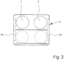
- Fig. 2 shows a schematic plan view of a preferred embodiment of a lens carrier 5 for receiving at least one, in the illustrated example, in particular two or more to be processed lenses 2.
- a lens carrier 5 for receiving at least one, in the illustrated example, in particular two or more to be processed lenses 2.
- lens processing or spectacle lens processing usually two lenses to be processed 2 and a pair of lenses are received by a lens carrier 5 , This is also preferred here.
- the lens carrier 5 preferably has a coding 5A, for example a barcode or the like, with important processing data, data for identification and / or other information for both lenses 2 or for each lens 2 a separate coding 5A, as in FIG Fig. 2 hinted at.
- the coding 5A particularly preferably contains an identification or order number or the like for the respective lens (s) 2, so that by means of the identification or order number a processing plan and / or processing status or required processing steps, processing sequences, processing data and / or other information, for example via a corresponding server system, database system or the like, in particular a system controller 21, as in Fig. 6 indicated, determinable or retrievable.
- the distance between the lenses 2 in a lens carrier 5 is the same as the distance between a lens 2 in a lens carrier 5 to the adjacent lens 2 in an immediately adjacent lens carrier 5. This simplifies the handling or positioning, especially in the processing facilities 3.
- This Distance is preferably 130 mm in the illustrated embodiment.
- the length of the lens carrier 5 is preferably twice, so here 260 mm.
- the lens carrier 5 is preferably box-like in the illustrated embodiment and / or at least substantially square in plan view.
- the lens carrier 5 has in the illustrated embodiment preferably additional storage or recording places, for example, for tools, in particular polishing tools on, as in Fig. 2 indicated by dashed lines.
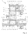
- Fig. 3 shows in a schematic representation or enlargement of Fig.1 a preferred construction of a proposed transfer device 9.
- the transfer device 9 preferably has a (first) conveyor 14 for longitudinal conveying (conveying in the direction F one of the transport tracks T, in particular the first transport track T1) and a (second) conveyor 15 for transverse conveying (conveying transversely or perpendicular to the conveying directions F or transport tracks T or to the transport track change).
- the conveyors 14 and 15 are preferably as well as the conveyors 8 and / or 10 designed as a belt or belt conveyor.
- the conveyors 10 preferably include belts or straps 10A and associated actuators 10B.
- the conveyors 14 preferably each have bands or straps 14A and associated drives 14B.
- the conveyors 15 preferably comprise belts or belts 15A and associated drives 15B.
- the transfer device 9 is preferably designed for receiving and temporarily storing or storing at least one lens 2 or a lens carrier 5 and, for this purpose, has in particular a bearing or receiving region 19, as in FIG Fig. 3 indicated by dashed lines.
- This or this is preferably formed in the illustrated embodiment by the conveyor 14, which has a sufficient length for this purpose.
- the length of the conveyor 14 is at least the simple length of a lens carrier 5, in the illustrated embodiment even at least twice the length of the lens carrier 5 to this preferably next to or in the conveying direction F1 before or upstream of the conveyor 15 for cross-promotion or record their lift table 15C or to be able to temporarily store.
- the receiving area 19 is preferably assigned a suitable stop device 18 (for example with a stop that can be moved or folded into the movement path or a singler) for stopping the or a lens carrier 5 in the receiving area 19 as required.
- the stop device 18 may stop or stop a lens carrier 5 - here in the receiving area 19 - in particular also when the conveyor 14 continues to run.
- suitable sensors 16 such as photoelectric sensors , Barcode reader or the like
- the length of the conveyor 14 or the transfer device 9 in the conveying direction F1 at least substantially equal to the distance between adjacent processing devices 3 and adjacent conveyors 8 and the aisle width between adjacent processing devices 3, as already mentioned, or at least the length of two lens carriers 5th
- processing devices 3 are preferably set up generally at least at substantially the same intermediate distance. Accordingly, preferably identical transfer devices 9 can be inserted or arranged therebetween.
- the conveying device 15 for transverse conveying has, as in Fig. 3 indicated in the transfer device 9 according to the illustrated embodiment, preferably an intermediate conveyor with belts or straps 15D between the two transport tracks T1 and T2 and between the conveyor 14 and the adjacent conveyor 10 on.
- the conveyor 15 preferably has a common drive 15B for driving the belts 15A and, if present, 15D.
- the bands or straps 15A are preferably arranged in pairs between the straps 14A of the conveyor 14 and the straps 10A of the conveyor 10 and are each preferably supported by a lifting element, in particular a lifting table 15C.
- the lifting element or the lifting table 15C or the lifting elements / lifting tables 15C and thus the associated bands or straps 15A are preferably (not shown) by means of an associated lifting device can be raised and lowered as needed.
- the conveyor 14 can receive and temporarily store or store a lens carrier 5 from an upstream processing device 3, in particular in the receiving region 19 and / or above the lifting table 15C or over the belts or straps 15A. If necessary, the transfer device 9 or its conveying device 14 can further convey the lens carrier 5 to the downstream processing device 3 or release it again. Alternatively, the transfer device 9 or its conveying device 15 can change the lens carrier 5 to the transport track T2, ie convey it crosswise. In this case, the lift table 15C is raised until the lens carrier 5 (in FIG Fig. 3 not shown) lifted and lifted off the belts or straps 14 A of the conveyor 14.
- the lens carrier 5 is conveyed by means of the bands or straps 15A - in the illustrated example via the optional intermediate conveyor or the straps or belts 15D - to the second transport track T2 or to the belts or straps 15A there.
- the transverse conveying and the lifting table 15C in the transport track T2 and in the conveyor 10 with or similar raised.
- a preferred lateral stop 15E which protrudes laterally upwards beyond the conveyor 10 or its bands or belts 10A, prevents the lens carrier 5 from being conveyed too far in the transverse direction or from the lens carrier 5 being conveyed laterally beyond the conveyor 10 ,
- the conveyor 15 or its lifting tables 15C are lowered again and thus the lens carrier 5 is transferred to the conveyor 10 or placed on the belts or straps 10A, so that now a promotion along the second transport track T2 by means of the conveyor 10 can take place ,
- the conveyor 15 is integrated for transverse conveying in the conveyor 10 for longitudinal conveying, since no separate conveyor for longitudinal conveying the transfer device 9 is provided in the second transport track 10, in contrast to the conveyor 14 for longitudinal conveying the transfer device 9 in the first transport track T1 , However, basically Such an additional conveyor 14 of the transfer device 9 may be provided in the second transport track T2.
- the transfer device 9 can not only for a change of the lens carrier 5 from the first transport track T1 to the second transport track T2, but of course for the reverse change, in particular for introducing a lens 2 or a lens carrier 5 in the transport track T1 for processing in one subsequent processing device 3, are used.
- the lens carrier 5 is positioned by the second transport track T2 or the associated conveyor 10 above the conveying device 15 for transverse conveying or its lifting table 15C in the second transport track T2.
- the positioning is preferably carried out by means of a stop device 18, for example by means of the stopping device 18 shown in dashed lines, which is arranged in particular in the second transport track T2 or after the lifting table 15C.
- the positioning of the transversely conveyed lens carrier 5 in the transport track T1 can in turn be facilitated or fixed by an optional lateral stop 15E.
- the transfer device 9 preferably serves both to introduce lenses 2 or lens carriers 5 into the first transport track T1 and to remove lenses 2 or lens carriers 5 from the transport track T2 to another transport track, here the second transport track T2.
- the transfer device 9 is in particular designed such that a lens 2 or a lens carrier 5 can be transversely conveyed or introduced into the first transport track T1, while another lens 2 or another lens carrier 5 is located in the receiving region 19 or temporarily stored there is cached.
- lenses 2 or lens carriers 5 can also be introduced between other lenses 2 or lens carriers 5 in the first transport track T1.
- the transfer device 9 allows a selective advancement of a lens 2 or a lens carrier 5 from the previous processing device 3 (in the first transport track T1) or from the receiving area 19 to the next processing device 3 as well as a discharging or Quer dealtn from the first transport track T1 to another transport track T, here the second transport track T2.
- the transfer device 9 thus forms a switch, with in particular upstream receiving area 19 for temporary storage.
- the transfer device 9 Since the transfer device 9 is preferably also designed for the already mentioned introduction of lenses 2 or lens carriers 5 into the first transport track T1, the transfer device 9 forms in particular a universally applicable switch, which, starting from the first conveying direction F1, branches off for transverse conveyance to the discharge as well slipping in particular over the same transverse conveying in the opposite direction and for further promotion in the first conveying direction F1 allows. This enables a very compact design with universal applicability.
- the transfer system 4 or the second transport track T2 preferably stops lenses 2 or lens carriers 5 before the transverse conveyance of the transfer device 9, in particular for introduction into the second transport track T2, for example in an upstream stop area 24, as dashed lines in Fig. 3 indicated, in particular by means of an associated stop device 18 o.
- the transfer system 4 or the second transport track T2 preferably stops lenses 2 or lens carriers 5 before the transverse conveyance of the transfer device 9, in particular for introduction into the second transport track T2, for example in an upstream stop area 24, as dashed lines in Fig. 3 indicated, in particular by means of an associated stop device 18 o.
- the like. Enables, so that an undisturbed slipping of lenses 2 and lens carriers 5 can be carried out in the second transport track T2.
- the stop region 24 is assigned a sensor 16 for detecting or identifying lenses 2 or lens carriers 5 in the stop region 24.
- sensors 16 are also associated with the lifting tables 15C or arranged in the region of the conveying devices 15 of the first and / or second transport track T1 or T2, respectively, in order to be able to detect or identify lenses 2 or lens carriers 5 there.
- At least one sensor 16 which is assigned to a transfer device 9 and / or the receiving region 19 and / or the stop region 24, is assigned to the downstream processing device 3, so that lenses 2 or lens carriers 5 arriving via this sensor 16 or these sensors 16 can be detected and preferably identifiable to the processing in the associated processing device 3 suitable lenses 2 - in particular under Recourse to or consideration of the processing plan and processing status of the respective lens 2 - recognize and be able to request as needed.
- Fig. 4 shows in a schematic, enlarged view of Fig. 1 a preferred construction of a changing device 11.
- the changing device 11 preferably has a conveyor 15 for transverse conveying similar to the conveyor 15 of the transfer device 9, so that reference is made to the relevant embodiments.
- the conveying device 15 of the reversing device 11 preferably has no or a very small intermediate conveyor, in particular since the two transport tracks T2 and T3 are preferably very narrow or (much) narrower than the transport tracks T1 and T2 next to each other , that is, the intermediate spacing is preferably smaller.
- the drive 15B of the conveyor 15 is preferably not arranged between the assigned transport tracks T2 and T3, but preferably laterally, in particular on the transport track T2 to the transport track T1.
- the lifting devices for the lifting tables 15C not shown.
- the lifting elements or lifting tables 15C and thus the belts or straps 15A of the conveyor 15 in the changing device 11 are preferably raised and lowered in a corresponding manner, as is the case with the transfer device 9, so that reference is made to the relevant description.
- the conveying direction of the transverse conveying by the conveying device 15 can preferably be changed in the changing device 11 as well as in the transfer device 9, the drive 15B thus operate in different directions to selectively or, if necessary, from the second transport track T2 to the third transport track T3 or Lensenarme 5 to be able to change or promote conversely.
- a changing device 11 and a transfer device 9 or their conveying devices 15 for transverse conveying can also be combined with one another or form a structural unit or be arranged in extension to one another.
- a lift table 15C can be omitted.
- the transfer device 9 can then permit a change over the second or middle transport track T2 into the third transport track T3 or form an exchange device.
- the distance between the first and second transport tracks T1 and T2 is preferably greater than the distance between the second and third transport tracks T2 and T3.
- the space requirement of the processing devices 3 for the reception and storage of lenses 2 on the respective conveyor 8 or a lens carrier 5 arranged thereon can be taken into account.
- storage devices or tanks or the like for the processing devices 3 can also be arranged under the transport tracks T or conveyors 10 and / or transfer devices 9.
- Fig. 5 shows a schematic representation of another embodiment of the proposed Appendix 1.
- Fig. 5 illustrates that the proposed Appendix 1 can be very easily expanded by integration or integration of other processing equipment 3 - that can be extended.
- further processing devices here at a processing or production line ending with the output station 6 were retrofitted (in Fig. 5 to the left thereof) further processing devices 3, here by way of example a further processing device 3D for polishing and an additional processing device 3G for coating, are integrated.
- the transfer system 4 has been extended accordingly. If necessary, the dispensing station 6 can then also be rebuilt and arranged, for example, at the end, as indicated by dashed lines by position 6 '.
- the proposed Appendix 1 allows optimized processing and utilization of the often different processing capacities of the various processing facilities 3.
- lenses 2 and lens carrier 5 with lenses 2 optionally to the original processing device 3D on the right side or to the further processing device 3D on the left side be promoted, with a forward funding on the second transport track T2 and, if necessary, a return promotion in particular on the third transport track T3, for example for subsequent processing in the right-hand processing device 3F can take place.
- circulation or circulation K of the lenses 2 or lens carriers 5 can take place via the second transport track T2 in one direction and the third transport track T3 in the opposite direction.
- a circulation or circulation K of the lenses 2 or lens carrier 5 is made possible or formed by corresponding transverse connections or cross-conveyances between the two transport tracks T2 and T3. This can in particular enable a storage of lenses 2 or lens carriers 5 and / or prevent or minimize the formation of undesirable congestion.
- the lenses 2 or lens carriers 5 are discharged or conveyed to desired processing devices 3 as required and / or available. This takes place, in particular, by corresponding transverse conveying and / or a change to the first transport track T1 or to a transfer device 9 assigned or arranged upstream of the desired processing device 3.
- a corresponding circulation or circulation K of lenses 2 or lens carriers 5 is in the proposed Appendix 1 according to the in Fig. 6 shown, another embodiment or according to the proposed method preferably also possible or provided.
- Fig. 6 is schematically indicated that circulate in the circulation or circle promotion K several lens carrier 5 or conveyed in a cycle, for example, until the next or a desired processing device 3 for receiving or Zuföd réelle for the appropriate processing is already.
- the extension section is preferably angled.
- the system 1 and the transport lanes T have here therefore in particular an L-shape.
- other particularly polygonal arrangements or even an at least substantially rectilinear arrangement or other arrangements, in particular depending on the structural conditions, are possible.
- the original Appendix 1 with the original processing devices 3A, 3B, 3C, 3D, 3F and 3G (in FIG Fig. 6 above), for example, to additional processing devices 3C, 3D and 3E (in Fig. 6 on the left) added or expanded.
- the extension of the transfer system 4 takes place in the illustrated embodiment, preferably via connecting devices 22, in particular corresponding extensions, deflections, corner connectors and / or the like., Particularly preferably to further conveyors 10 and / or transfer devices 9 o. The like.
- To connect, and / or the first extend second and / or third transport track T.
- the transport lanes T2 and T3 or the possible or preferred circular conveying K are extended accordingly.
- the illustrated example originally ended the circle promotion K and the transport lanes T in the area of the delivery station 6. Only the extension has led here to the exemplary illustrated L-shaped structure.
- the required additional transfer devices 9 or conveyors 10 and / or changing devices 11 when supplementing the transfer system 4 are preferably connected directly to the bus system 13. Accordingly, the effort for the expansion can be minimized, so an extension is very easy.
- the transfer devices 9, conveying devices 10 and / or changing devices 11 are controlled by the preferably central transfer control device 12, in particular a programmable logic controller, and / or via the bus system 13 and that the conveying devices 8 of the processing devices 3 from the respective processing device. 3 or whose machine control 20 are controlled.
- the transfer system 4 is controlled in total by the control device 12. This allows an optimal sequence and / or a very robust, less prone to interference control. Furthermore, this facilitates an extension of the system 1.
- individual, multiple or all processing devices 3 or their machine controls 20 are preferably connected to the central system or system controller 21, for example via a data network, a (further) bus system 25, an Ethernet cabling o.
- the system controller 21 can be a server, a database system or the like.
- the system controller 21 manages the jobs to be executed by the installation 1 or the lenses 2 to be processed by the installation 1 or the information required for the machining, for example, machining data, machining plans or machining sequences, machining stations, planned or required processing steps, optical and / or geometric information or data of the lenses 2 and / or other information, for example on tools to be used or available o.
- the system controller 21 manages the jobs to be executed by the installation 1 or the lenses 2 to be processed by the installation 1 or the information required for the machining, for example, machining data, machining plans or machining sequences, machining stations, planned or required processing steps, optical and / or geometric information or data of the lenses 2 and / or other information, for example on tools to be
- the transfer controller or control device 12 on the one hand and the system controller 21 on the other hand are coupled to each other for information or data exchange, as in Fig. 6 indicated schematically.
- the system controller 21 can control the transfer system 4 or the transfer devices 9, conveyors 10 and / or changing devices 11 in particular via the control device 12 such that desired lenses 2 or lens carriers 5 to the respective processing devices 3, if necessary only on appropriate request of the respective Processing device 3 out to be promoted.
- different or all processing machines 3 can individually request or pick up workpieces or lenses 2 or lens carriers 5 to be processed with lenses 2 from the transfer system 4, perform the respective required processing, and return the lens 2 to the transfer system 4 after processing pass or passed to this.
- a processing device 3 can autonomously determine, in particular taking into account a processing plan and processing status (this processing data or information is queried or provided in particular by the system controller 21 or a database, a data memory or the like) whether one (in particular near or short Lens 2 located in front of the processing device 3 is suitable for processing in the respective processing device 3 in order to request this or the corresponding lens carrier 5 with appropriate capacity of the processing device 3 or to allow it to be conveyed.
- a plurality of processing devices 3 for the same processing can independently select and / or request a lens 2 for the next processing.
- the request is made by a processing device 3 in particular when it has been cleared.
- the request can also be made beforehand to minimize waiting times.
- the respective processing device 3 outputs a corresponding information or a corresponding signal to the control device 12 when a lens 2 or a lens carrier 5 is to be dispensed after the processing to the downstream transfer device 9 or to the transfer system 4 or has already been dispensed.
- the respective lens 2 or the respective lens carrier 5 is then received by the transfer system 4 or the transfer device 9 downstream of the respective processing device 3, for example into the receiving region 19, and / or further conveyed, for example to a downstream processing device 3 and /. or in the second transport track T2 or the circuit promotion K introduced again. This can be done either by the transfer system 4 or its control device 12 independently and / or in coordination and / or in dependence on the system controller 21.
- the processing device 3 ready for receiving a lens 2 or a lens carrier 5 is then conveyed back to a lens 2 or a lens carrier 5, the selection - as already mentioned - being particularly preferred by the respective processing device 3 or its machine control 20 and / or by the system controller 21, particularly preferably taking into account data relevant for the processing, such as the processing plan and the processing state, in particular from the system controller 21.
- the control of the feed is then preferably via the control device 12, but if necessary, can also be controlled by the respective processing device 3 and the machine controller 20, as later with reference to another embodiment according to Fig. 7 explained in more detail.
- a processing device 3 or its conveying device 8 preferably transfers a lens 2 or a lens carrier 5 to the transfer system 4 or to a transfer device 9, preferably downstream of the transfer device F1, if or when there is space to receive it when the respective or associated receiving area 19 is free.
- the processing device 3 or its machine control 20 preferably communicates via the system controller 21 or directly with the transfer control or control device 12 or the transfer system 4 or the respective transfer device 9.
- the delivery takes place, in particular, via the transfer system 4 or the upstream transfer device 9.
- the delivery is preferably triggered by a request from the respective processing device 3 or from the system controller 21, if this has been recognized or communicated that the processing device 3 or its Conveyor 8 has been cleared.
- the conveying devices 8 of the processing devices 3 can in particular also accommodate a plurality of lenses 2 or lens carriers 5 with lenses 2 as required (simultaneously).
- the term “retracting” is accordingly to be understood as meaning that the respective processing device 3 or its delivery device 8 is ready for receiving a lens 2 or a lens carrier 5, even if one or more lenses 2 or lens carrier 5 in the Processing device 3 and its conveyor 8 are located.
- the feed can in particular be effected selectively from the receiving area 19 of an upstream transfer device 9 or through transverse conveyance via the conveyor 15 and subsequent longitudinal conveyance via the conveyor 14 of the upstream transfer device 9, ie by conveyance from the second transport track T2.
- the control device 12 and / or the request of the respective processing device 3 and / or a prioritization of processing or lenses 2 by the system controller 21 controls the process.
- the lens 2, which previously processed the processing device 3, or the lens carrier 5 carrying it, may be produced by the downstream transfer device 9 be recorded and cached if necessary in the receiving area 19. However, if necessary, a further promotion can take place directly without stopping.
- the further promotion may consist in that the lens 2 or the lens carrier 5 is further conveyed to the next processing device 3, ie in the conveying direction F1 further along the first transport track T1, ie the next processing device 3 or its conveyor 8 is conveyed.
- a transverse conveying by means of the conveyor 15 and a change in the second transport track T2 and possibly further in the third transport track T3 done.
- a further promotion to another processing device 3 or possibly to the dispensing station 6 can take place.
- Fig. 7 shows a schematic representation of yet another embodiment of the proposed plant 1.
- Both conveyors 15 and 15 'of a transfer device 9 are preferably operable independently of each other. This makes it possible for the respective processing device 3 to control the upstream transverse conveying via the upstream conveying device 15 and the downstream transverse conveying via the downstream conveying device 15 'directly or independently, in particular independently of the in Fig.
- the associated or arranged therebetween conveyor 14 is optionally provided, so may also be omitted, and is preferably controlled by the upstream or downstream processing device 3 and the machine controller 20.
- a detection of lenses 2 or lens carriers 5 is particularly preferably made possible by sensors 16 which are also connected in particular to the machine control 20.
- sensors 16 it is possible, for example, to identify lenses 2 or lens carriers 5 located in the transport track T2 or circulation or circulation conveyor K and to dispose of suitable lenses 2 or lens carriers 5 for processing in the respective processing device 3 or into the first Leave transport track T2 change, in particular independently of other processing devices 3 and their machine control 20 and / or independent of the transfer control or control device 12 and / or independent of the system controller 21st
- the machine controller 20 are preferably associated with the respective processing device 3 or arranged in this, but can also be separated therefrom or arranged centrally.
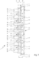
- Fig. 8 shows a schematic representation of another embodiment of the proposed plant 1.
- this embodiment preferably at least a substantially U-shaped arrangement, in particular the first or second transport track T1 or T2 is formed.
- two groups or rows of processing devices here for example a first group of processing devices 3A, 3B and 3C and a second group of processing devices 3D, 3E and 3F, are formed or arranged opposite one another and / or with conveying devices 8 arranged on mutually facing sides and / or arranged such that the associated transport tracks T1 and / or T2 of the two groups are preferably parallel to each other.
- the system 1 or the transfer system 4 has a transverse connection of the two groups of processing devices 3 via a conveyor 10 'and / or 10 "transversely or interconnected.
- the conveyor 10 forms a leg or portion of the preferably at least substantially U-shaped arrangement or a part the preferably substantially U-shaped course of the first or second transport track T1 or T2, here the second transport track T2.
- one or more processing devices 3 can be arranged at this section.
- the system 1 or the transfer system 4 has a return line R on.
- the return conveyor R preferably has the (second) conveyor 10 "or is formed thereby.
- a circle promotion or circulation particularly preferably via the first or second transport track T1 or T2 possible.
- this is the return line R for the first or second transport track T1 or T2 (in the illustrated embodiment, only for the second transport track T2) provided.
- the return conveyor R allows a return conveyance in the return direction FR, so that a circulation or circulation of the lenses 2 or lens carrier 5 is made possible via the second transport track T2 without reversing the conveying direction F2 and without change in the opposite direction F3.
- the system 1 or the transfer system 4 preferably has a receiving station 7 and / or delivery station 6 or corresponding conveyor devices 10 (in Fig. 8 dashed lines indicated on the left side) as an inlet and / or outlet for lenses 2 and 5 lens carrier.
- the return conveyor R or conveyor 10 is particularly preferably arranged in the region of the beginning and / or end of the transport track T1 or T2 and / or the usual processing and / or in the region of the receiving station 7 or discharge station 6.
- Particularly preferred is the return line R or conveyor 10 "connected via appropriate switches.
- other constructive solutions and / or arrangements are possible, in particular depending on the location and training or arrangement of the receiving station 7 and / or dispensing station. 6
- Fig. 8 allows the return line R a circle promotion or circulation of the lenses 2 and Linsenvic 5. Accordingly, a third transport track T3 for return promotion or circulation is not required. However, the return link R and the third transport lane If necessary, T3 can also be combined or used in addition, in particular depending on the structural conditions and / or existing processing facilities 3.
- the return conveyor connection R can also be arranged at a different location or form only one circuit for some of the processing devices 3, for example connected between the processing device 3B and 3C on the one hand and between the processing device 3D and 3E on the other hand form or enable shorter or smaller circulation.
- the system 1 or the transfer system 4 conveyors 23 for curve promotion in particular to straight sections of the respective transport track, here T2, and / or various conveyors 10, 10 'and / or 10 "and / or the return line R with the transport track
- the curve promotion can be achieved that the alignment of the lenses 2 and lens carrier 5 with respect to the respective conveying direction F remains the same so for example in a lens carrier 5 with two lenses 2 always the same lens 2 front.
- the two groups of processing devices 3 and the two legs of the particularly preferred U-shaped arrangement are preferably arranged relatively close to each other in the illustrated embodiment and / or spaced so that the gap forms an access option for an operator, not shown.
- the cross connections or conveying devices 10 'and / or 10 are designed such that they can be loosened or opened or folded away as needed Alternatively or additionally, these can also be raised or lowered and connected, for example, via corresponding vertical conveyors or downgrades that a preferably free access to the gap is made possible.
- the intermediate space can also be used for resource containers for processing devices 3, for example for a coolant container, a container for chips, a container for cooling liquid or the like.
- the containers can in particular in the space and / or below the transfer system, particularly preferably be arranged below the second transport track T2.
- Fig. 9 shows in a very schematic representation of a block diagram of a preferred control structure of a proposed Appendix 1.
- the system 1 or the transfer system 4 preferably has an in particular central transfer or control device 12.
- This is in particular a so-called band master computer. If necessary, it can also be a program and / or multiple networked computers, computers, controllers o. The like. Act.
- the transfer or control device 12 serves, in particular, for controlling the production flow or the conveyance of the lenses 2 or lens carriers 5, such as circulation or circulation and / or delivery of lenses 2 or lens carriers 5 to processing devices 3 and away from them.
- the control device 12 particularly preferably controls the transfer devices 9, conveying devices 10 and / or changing devices 11, conveying devices 14 for longitudinal conveying, conveying devices 15 for transverse conveying and / or stopping devices 18, the transfer devices 9 preferably additionally or alternatively also by the processing devices 3 or their machine control 20 - in particular when connected to the bus system 13 - (direct) can be controlled.
- the system or system controller 21 is preferably coupled or connected via a (further) bus system 25 to the processing devices 3 or their machine controllers 20.
- a (further) bus system 25 to the processing devices 3 or their machine controllers 20.
- other types of connection are possible here as well.
- the controller 12 may also be connected to the system controller 21 via the bus system 25 or a separate connection for data exchange.
- the system controller 21 preferably forms a lens management system.
- the system controller 21 serves, in particular, for the acceptance or recording of orders O and / or the administration of orders, production data and / or lens blanks and / or the provision of interfaces to other systems, For example, to systems or modules for the lens design that determine the desired geometric shape of lenses 2 and / or the required processing or processing steps, in particular depending on desired optical properties.
- production data P which in particular provide, manage and / or maintain processing plans (processing steps and / or orders or sequences) and processing statuses (processing conditions or information on processes to be executed next), and / or generate.
- the production data P are made available in particular by the system controller 21 to the processing devices 3 or their machine controls 20 and / or can be queried by them, as indicated by a corresponding arrow in FIG Fig. 9 indicated schematically.
- the system 26 serves, in particular, for the visualization and / or management of machine states, that is to say states of the processing devices 3, production data, process data and / or other information.
- system 26 preferably serves the management of macros and / or reporting.
- the system 26 may be appropriate programs, applications o. The like. And / or one or more computers, such as a server o. The like., Act. The same applies to the system controller 21 and / or control device 12.
- the processing devices 3 or their machine controllers 20 may preferably further information I, such as process data u. Like. Communicate to the system 26, as indicated by a corresponding arrow in Fig. 9 indicated.
- system 26 may also be connected to the bus system 25.
- data exchange can also take place via the system controller 21.
- the system controller 21 and the system 26 may have production data P and / or data status information S, such as order status, as indicated by arrow P / S in FIG Fig. 9 indicated, exchange.
- production data P and / or data status information S such as order status, as indicated by arrow P / S in FIG Fig. 9 indicated, exchange.
- the system controller 21 and the controller 12 may have production data P as indicated by a corresponding arrow in FIG Fig. 9 indicated, and / or status information S, in particular data on the order status, as indicated by a corresponding arrow A in Fig. 9 indicated, exchange and / or adjust.
- control device 12 is preferably also connected to the further bus system 25 and / or in any other way or connected to the data exchange or connectable.
- the processing devices 3 or their machine controllers 20 may preferably have order information A, such as information on the status, in particular order status, requests and / or requests, as indicated by a corresponding arrow in FIG Fig. 9 indicated, exchange.
- order information A can be transmitted to the control device 12 or communicated to the control device 12 and / or a request for a lens 2 or a lens carrier 5 can be transmitted to the control device 12.
- information about lenses 2 or lens carriers 5 which are preferably detected or identified by the sensors 16 can be transmitted from the sensors 16 directly or via the control device 12 to individual or multiple or all processing devices 3 or their machine control 20.
- This information exchange takes place, in particular, in the context of the requirement of new lenses 2 or lens carriers 5 by the processing devices 3, as indicated by the double arrow A in FIG Fig. 9 indicated.
- This information exchange can also take place taking into account further data or information, in particular of process data P, particularly preferably processing plans and processing stations, which are preferably provided by the system controller 21.
- the processing devices 3 can preferably independently select and / or request new orders or lenses 2 for processing. This allows, according to a particularly preferred aspect, a quasi-arbitrary or independent latching or insertion of processing equipment 3 in the Appendix 1.
- the proposed Appendix 1 and the proposed method for processing optical lenses 2 is very flexible. In particular, an improved or optimized utilization of processing capacities can be achieved. Furthermore, a very flexible processing and adaptation to different circumstances is possible. For example, downtimes or failures of individual processing devices 3 can be compensated very easily and / or optimally, in particular if other or alternative processing devices 3 are available. Alternatively or additionally, an intelligent center of gravity control can take place, for example in such a way that a processing device 3 which is particularly suitable for a particular processing is used primarily for this processing, that is, for example, a lathe with a particularly large chip space for processing particularly long or bulky chips during machining Lenses 2.
- the proposed Appendix 1 and the proposed method allow in particular a very large flexibility also in the processing of lenses 2 with different shapes and / or different materials.
- the usual processing or production lines can be avoided, which are primarily aligned to the processing of lenses 2 made of a particular material or lenses 2 of a particular shape.
Landscapes
- Engineering & Computer Science (AREA)
- Mechanical Engineering (AREA)
- Health & Medical Sciences (AREA)
- Manufacturing & Machinery (AREA)
- Ophthalmology & Optometry (AREA)
- Multi-Process Working Machines And Systems (AREA)
- General Factory Administration (AREA)
- Automatic Assembly (AREA)
- Eyeglasses (AREA)
- Branching, Merging, And Special Transfer Between Conveyors (AREA)
- Control Of Conveyors (AREA)
- Container, Conveyance, Adherence, Positioning, Of Wafer (AREA)
- Grinding And Polishing Of Tertiary Curved Surfaces And Surfaces With Complex Shapes (AREA)
Claims (8)
- Installation (1) destinée à traiter des lentilles optiques (2) pour des lunettes,
comprenant plusieurs dispositifs de traitement distincts (3C, 3D) pour le traitement de mise en forme et/ou le polissage indépendants des lentilles (2), et
comprenant un système de transfert (4) servant au transport des lentilles (2) vers les dispositifs de traitement et en provenance de ces derniers (3),
dans laquelle à chaque dispositif de traitement (3) est associé son propre dispositif de transport (8) pour le transport des lentilles (2),
le système de transfert (4) comprenant une première piste de transport (T1) pour le transport de lentilles (2) d'un dispositif de traitement (3) vers le suivant et une seconde piste de transport (T2) parallèle pour le transport parallèle de lentilles (2),
deux groupes de dispositifs de traitement (3) étant disposés l'un en face de l'autre et/ou formés par des dispositifs de transport (8) disposés sur des côtés en regard l'un de l'autre et/ou étant disposés de telle sorte que les pistes de transport associées (T1, T2) des deux groupes soient parallèles l'une à l'autre, les deux groupes étant reliés l'un à l'autre par un dispositif de transport (10', 10"), le système de transfert (4) présentant une liaison de retour (R) pour la circulation des lentilles (2), de telle sorte que les lentilles (2) puissent être acheminées vers tous les dispositifs de traitement (3) ou certains d'entre eux dans un ordre quelconque et/ou plusieurs fois, la liaison de retour (R) présentant le dispositif de transport (10") ou étant formé à partir de celui-ci. - Installation selon la revendication 1, caractérisée en ce que la liaison de retour (R) est prévue pour la première ou la seconde piste de transport (T1, T2), de telle sorte qu'un transport circulaire ou une circulation soit possible par la première ou la seconde piste de transport (T1, T2).
- Installation selon la revendication 1 ou 2, caractérisée en ce que le dispositif de transport (10') forme une branche ou une partie d'un agencement sensiblement en forme de U ou une partie d'un tracé de préférence sensiblement en forme de U de la première ou la seconde piste de transport (T1, T2).
- Installation selon l'une quelconque des revendications précédentes, caractérisée en ce que la liaison de retour (R) relie la première ou la seconde piste de transport (T1, T2), de préférence dans la zone du début et de l'extrémité de la première ou la seconde piste de transport (T1, T2), et/ou en ce que la liaison de retour (R) est disposée dans la zone du début et/ou de l'extrémité de la piste de transport (T1, T2) et/ou du traitement normal et/ou dans la zone d'une station de réception (7) ou d'une station d'enlèvement (6).
- Installation selon l'une quelconque des revendications précédentes, caractérisée en ce que la liaison de retour (R) est reliée par des aiguillages correspondants.
- Installation selon l'une quelconque des revendications précédentes, caractérisée en ce qu'il est prévu plusieurs liaisons de retour (R).
- Procédé de traitement de lentilles optiques (2) pour des lunettes comprenant une installation (1) selon l'une quelconque des revendications précédentes,
les lentilles (2) étant transportées par le système de transfert (4) vers les différents dispositifs de traitement (3) sélectivement pour le traitement de mise en forme et/ou le polissage indépendants des lentilles (2),
les lentilles (2) étant transportées par des dispositifs de transport (9) du système de transfert (4) entre les dispositifs de traitement (3) sélectivement vers le dispositif de traitement suivant (3) ou vers une piste de transport (T2) parallèle,
les dispositifs de transfert (9) formant, avec les dispositifs de transport (8) des dispositifs de traitement (3), une première piste de transport (T1) et les lentilles (2) étant transportées sur une seconde piste de transport (T2), parallèle à la première piste de transport (T1) et passant au moyen des dispositifs de transfert (9) de la première à la seconde piste de transport (T1, T2) et inversement,
deux groupes de dispositifs de traitement (3) étant disposés l'un en face de l'autre et/ou formés par des dispositifs de transport (8) disposés sur des côtés en regard l'un de l'autre et/ou étant disposés de telle sorte que les pistes de transport associées (T1, T2) des deux groupes soient parallèles l'une à l'autre, une circulation des lentilles (2) s'effectuant par la première ou la seconde piste de transport (T1, T2) et la liaison de retour (R). - Procédé selon la revendication 7, caractérisé en ce que les lentilles (2) sont mises en circulation, jusqu'à ce qu'une sortie ou un transport transversal s'effectue vers la première piste de transport (T1) contenant le dispositif de traitement (3) ou vers un dispositif de traitement (3) souhaité.
Priority Applications (1)
| Application Number | Priority Date | Filing Date | Title |
|---|---|---|---|
| EP18177282.3A EP3415447B1 (fr) | 2012-03-09 | 2013-03-08 | Installation et procede destines a traiter des lentilles optiques |
Applications Claiming Priority (6)
| Application Number | Priority Date | Filing Date | Title |
|---|---|---|---|
| EP12001640 | 2012-03-09 | ||
| EP12003626 | 2012-05-09 | ||
| EP12003858 | 2012-05-16 | ||
| DE202012011690U DE202012011690U1 (de) | 2012-03-09 | 2012-12-06 | Anlage zum Bearbeiten optischer Linsen |
| EP13720773.4A EP2822883B1 (fr) | 2012-03-09 | 2013-03-08 | Installation et procédé permettant d'usiner des lentilles optiques |
| PCT/EP2013/000693 WO2013131656A2 (fr) | 2012-03-09 | 2013-03-08 | Installation et procédé permettant d'usiner des lentilles optiques |
Related Parent Applications (2)
| Application Number | Title | Priority Date | Filing Date |
|---|---|---|---|
| EP13720773.4A Division EP2822883B1 (fr) | 2012-03-09 | 2013-03-08 | Installation et procédé permettant d'usiner des lentilles optiques |
| EP13720773.4A Division-Into EP2822883B1 (fr) | 2012-03-09 | 2013-03-08 | Installation et procédé permettant d'usiner des lentilles optiques |
Related Child Applications (2)
| Application Number | Title | Priority Date | Filing Date |
|---|---|---|---|
| EP18177282.3A Division-Into EP3415447B1 (fr) | 2012-03-09 | 2013-03-08 | Installation et procede destines a traiter des lentilles optiques |
| EP18177282.3A Division EP3415447B1 (fr) | 2012-03-09 | 2013-03-08 | Installation et procede destines a traiter des lentilles optiques |
Publications (2)
| Publication Number | Publication Date |
|---|---|
| EP2998247A1 EP2998247A1 (fr) | 2016-03-23 |
| EP2998247B1 true EP2998247B1 (fr) | 2019-09-11 |
Family
ID=48084716
Family Applications (4)
| Application Number | Title | Priority Date | Filing Date |
|---|---|---|---|
| EP13720773.4A Active EP2822883B1 (fr) | 2012-03-09 | 2013-03-08 | Installation et procédé permettant d'usiner des lentilles optiques |
| EP16020045.7A Active EP3059189B1 (fr) | 2012-03-09 | 2013-03-08 | Installation et procédé permettant de préparer des lentilles optiques |
| EP15020175.4A Active EP2998247B1 (fr) | 2012-03-09 | 2013-03-08 | Installation et procédé destinés à traiter des lentilles optiques |
| EP18177282.3A Active EP3415447B1 (fr) | 2012-03-09 | 2013-03-08 | Installation et procede destines a traiter des lentilles optiques |
Family Applications Before (2)
| Application Number | Title | Priority Date | Filing Date |
|---|---|---|---|
| EP13720773.4A Active EP2822883B1 (fr) | 2012-03-09 | 2013-03-08 | Installation et procédé permettant d'usiner des lentilles optiques |
| EP16020045.7A Active EP3059189B1 (fr) | 2012-03-09 | 2013-03-08 | Installation et procédé permettant de préparer des lentilles optiques |
Family Applications After (1)
| Application Number | Title | Priority Date | Filing Date |
|---|---|---|---|
| EP18177282.3A Active EP3415447B1 (fr) | 2012-03-09 | 2013-03-08 | Installation et procede destines a traiter des lentilles optiques |
Country Status (5)
| Country | Link |
|---|---|
| US (3) | US9908714B2 (fr) |
| EP (4) | EP2822883B1 (fr) |
| CN (2) | CN107775486B (fr) |
| DE (2) | DE202012011690U1 (fr) |
| WO (1) | WO2013131656A2 (fr) |
Families Citing this family (41)
| Publication number | Priority date | Publication date | Assignee | Title |
|---|---|---|---|---|
| MY160654A (en) * | 2010-12-16 | 2017-03-15 | Novartis Ag | Method and apparatus for transferring objects between two consecutive processing stations being operated with different cycle speeds |
| DE202012011690U1 (de) | 2012-03-09 | 2013-03-13 | Schneider Gmbh & Co. Kg | Anlage zum Bearbeiten optischer Linsen |
| EP2992393B1 (fr) * | 2013-04-29 | 2019-09-11 | Essilor International | Système de calcul pour fabriquer une lentille ophtalmique |
| DE102014117291B4 (de) * | 2014-11-26 | 2017-08-31 | Holger Thomas Wallat | Lagersystem für Brillengläser |
| US10549400B2 (en) * | 2014-12-19 | 2020-02-04 | Schneider Gmbh & Co. Kg | Device and method for processing an optical lens |
| DE102015015040A1 (de) * | 2015-11-12 | 2017-05-18 | Schneider Gmbh & Co. Kg | Verfahren, Anlage und System zur Bearbeitung optischer Linsen |
| CN105382650B (zh) * | 2015-12-19 | 2018-02-09 | 湖南宇环智能装备有限公司 | 全自动双端面磨削生产线 |
| EP3214024B1 (fr) * | 2016-03-01 | 2018-06-27 | EWAB Engineering AB | Système de transporteur autonome |
| DE102016007837A1 (de) * | 2016-05-25 | 2017-11-30 | Schneider Gmbh & Co. Kg | Verfahren und System zur Bearbeitung optischer Linsen |
| CN106041697B (zh) * | 2016-05-28 | 2018-06-22 | 泉州泉港佳诚信息科技有限公司 | 一种自动转角度打蜡机 |
| IT201600107761A1 (it) * | 2016-10-26 | 2018-04-26 | Apes Srl | Impianto automatico di pulitura/lucidatura di oggetti in metallo |
| DE102016125278A1 (de) | 2016-12-14 | 2018-06-14 | Schneider Gmbh & Co. Kg | Vorrichtung, Verfahren und Verwendung zur Beschichtung von Linsen |
| US9988216B1 (en) | 2016-12-16 | 2018-06-05 | Amazon Technologies, Inc. | Parallel vertical recirculating gantry system |
| US10029865B1 (en) * | 2016-12-16 | 2018-07-24 | Amazon Technologies, Inc. | Parallel recirculating gantry system on a rollercoaster-style track |
| EP3336022A1 (fr) | 2016-12-19 | 2018-06-20 | Carl Zeiss Vision International GmbH | Système de fabrication de verres de lunettes |
| HUE051238T2 (hu) * | 2016-12-19 | 2021-03-01 | Zeiss Carl Vision Int Gmbh | Továbbító berendezés egy szállítótartály számára |
| DE102017001680A1 (de) | 2017-02-22 | 2018-08-23 | Schneider Gmbh & Co. Kg | Anlage und Verfahren zur Bearbeitung optischer Linsen |
| EP3479954A1 (fr) | 2017-11-07 | 2019-05-08 | Satisloh AG | Station de surfaçage pour la fabrication d'éléments optiques et installation de fabrication associée |
| DE102018007463B4 (de) * | 2018-09-04 | 2022-01-05 | Schneider Gmbh & Co. Kg | Vorrichtung und Verfahren zur Linsenbearbeitung sowie Bearbeitungseinrichtung für Linsen |
| US11067476B2 (en) | 2018-02-21 | 2021-07-20 | Schneider Gmbh & Co. Kg | Apparatus and method for measuring at least one optically effective object |
| US11498757B2 (en) * | 2018-06-12 | 2022-11-15 | Autostore Technology AS | Storage system |
| KR101971859B1 (ko) * | 2018-07-02 | 2019-04-24 | (주)대호테크 | 볼렌즈용 이재장치 |
| JP7052611B2 (ja) | 2018-07-13 | 2022-04-12 | 株式会社ダイフク | 物品仕分け設備 |
| SMP201900014B1 (it) | 2018-09-04 | 2021-05-07 | Schneider Gmbh & Co Kg | Dispositivo e procedimento per la lavorazione di lenti nonche' apparecchiatura di lavorazione per lenti |
| DE102018007494A1 (de) * | 2018-09-04 | 2020-03-05 | Schneider Gmbh & Co. Kg | Bearbeitungssystem zur Bearbeitung von Brillengläsern |
| EP3747641A3 (fr) * | 2019-06-07 | 2021-03-10 | Schneider GmbH & Co. KG | Procédé et appareil de fabrication de lentilles optiques |
| DE102019004489A1 (de) * | 2019-06-07 | 2020-12-10 | Schneider Gmbh & Co. Kg | Verfahren und Vorrichtung zum Herstellen von optischen Linsen |
| DE102020003578A1 (de) | 2020-05-20 | 2021-11-25 | Schneider Gmbh & Co. Kg | Beschichtungsanlage, Spannring und Magazin für Brillengläser und Verfahren zum Beschichten von Brillengläsern |
| DE102020005090A1 (de) | 2020-08-07 | 2022-02-10 | Schneider Gmbh & Co. Kg | Vorrichtung und Verfahren zum Bearbeiten optischer Werkstücke |
| EP3950223B1 (fr) | 2020-08-07 | 2024-10-02 | Schneider GmbH & Co. KG | Appareil et procédé de traitement de pièces optiques |
| US12370644B2 (en) | 2020-11-10 | 2025-07-29 | Schneider Gmbh & Co. Kg | Installation and method for processing ophthalmic lenses |
| DE102020006895A1 (de) | 2020-11-10 | 2022-05-12 | Schneider Gmbh & Co. Kg | Anlage zum Bearbeiten ophthalmischer Linsen |
| EP4275874B1 (fr) | 2022-05-10 | 2026-04-29 | Schneider GmbH & Co. KG | Installation et procédé permettant de traiter des lentilles ophtalmiques, ainsi qu'utilisation d'un dispositif de poussée |
| DE102021001248A1 (de) | 2021-03-08 | 2022-09-08 | Schneider Gmbh & Co. Kg | System zum Transport und zur Lagerung von Gegenständen sowie Verfahren zur Ausgabe von gelagerten Gegenständen |
| US20240150124A1 (en) | 2021-03-08 | 2024-05-09 | Schneider Gmbh & Co. Kg | System, method and use for picking objects for eyeglass manufacturing |
| DE102023110601B3 (de) * | 2023-04-25 | 2024-05-02 | Optotech Optikmaschinen Gmbh | Bearbeitungsvorrichtung und Verfahren zur formgebenden Bearbeitung von optischen Linsen durch Materialabtrag mit einer Vorbearbeitungsmaschine und einer Feinbearbeitungsmaschine |
| DE102023127476A1 (de) | 2023-10-09 | 2025-04-10 | Fraunhofer-Gesellschaft zur Förderung der angewandten Forschung eingetragener Verein | Fertigungslinie und Verfahren zum computergestützten Ermitteln bauteilbezogener Daten |
| EP4552794B1 (fr) * | 2023-11-07 | 2025-10-15 | Carl Zeiss Vision International GmbH | Procédé mis en oeuvre par ordinateur pour fournir un ordre d'occupation pour transférer des ébauches de lentille d'un premier support à un second support |
| CN117945091A (zh) * | 2024-02-06 | 2024-04-30 | 武汉帝尔激光科技股份有限公司 | 一种连续上下料机构、激光加工设备及其控制方法 |
| CN120081144B (zh) * | 2024-12-02 | 2025-12-05 | 无锡江岚智能装备有限公司 | 一种空压杆工装输送设备以及上下料方法 |
| KR102940981B1 (ko) * | 2025-09-11 | 2026-03-19 | (주)엠엑스앤 | 고정밀 및 저비용의 모듈형 공정 수행 컨베이어 시스템 |
Citations (3)
| Publication number | Priority date | Publication date | Assignee | Title |
|---|---|---|---|---|
| US4727684A (en) * | 1986-01-16 | 1988-03-01 | Tipton Manufacturing Corporation | Full-automatic work finishing machine with high-speed rotating barrel containers |
| DE19815728A1 (de) * | 1998-04-08 | 1999-10-14 | Wernicke & Co Gmbh | Anlage zum Formbearbeiten der Ränder von Brillengläsern |
| DE102004021696A1 (de) * | 2004-04-30 | 2005-11-24 | Schneider Gmbh + Co. Kg | Aufblockstation |
Family Cites Families (44)
| Publication number | Priority date | Publication date | Assignee | Title |
|---|---|---|---|---|
| FR2288588A1 (fr) * | 1974-07-12 | 1976-05-21 | Essilor Int | Machine pour l'usinage en serie des deux faces d'une lentille ophtalmique |
| CH597059A5 (fr) | 1976-12-15 | 1978-03-31 | Micafil Ag | |
| JPS5619635A (en) | 1979-07-27 | 1981-02-24 | Hitachi Ltd | Manufacturing apparatus |
| JPS60146646A (ja) | 1983-12-30 | 1985-08-02 | Hitachi Ltd | パレツト移載装置 |
| US5024315A (en) * | 1985-08-19 | 1991-06-18 | O-I Neg Tv Products, Inc. | Method of distributing workpieces between a conveyor and workstations |
| DE3614165A1 (de) | 1986-04-26 | 1987-10-29 | Kloeckner Humboldt Deutz Ag | Transportsystem fuer serienfertigungen |
| JP2565786B2 (ja) | 1990-03-09 | 1996-12-18 | 三菱電機株式会社 | 自動搬送装置及び方法 |
| JPH05181527A (ja) | 1991-12-27 | 1993-07-23 | Mitsubishi Electric Corp | 自動搬送装置 |
| US5555504A (en) | 1994-06-10 | 1996-09-10 | Johnson & Johnson Vision Products, Inc. | Production line tracking and quality control system |
| US5804107A (en) | 1994-06-10 | 1998-09-08 | Johnson & Johnson Vision Products, Inc. | Consolidated contact lens molding |
| IL113693A0 (en) * | 1994-06-10 | 1995-08-31 | Johnson & Johnson Vision Prod | Contact lens production line pallet system |
| DE19504457A1 (de) * | 1995-02-10 | 1996-08-14 | Bosch Gmbh Robert | Modulare Fließfertigungsanlage |
| DE19609201A1 (de) * | 1996-03-09 | 1997-09-11 | Bosch Gmbh Robert | Fördereinrichtung zum Transport von Werkstücken, insbesondere von Werkstückträgern |
| FI108715B (fi) * | 1998-03-09 | 2002-03-15 | Pmj Automec Oyj | Kokoonpanolinja |
| DE29823464U1 (de) * | 1998-04-08 | 1999-06-10 | Wernicke & Co GmbH, 40231 Düsseldorf | Anlage zum Formbearbeiten der Ränder von Brillengläsern |
| ES2186349T3 (es) | 1998-04-17 | 2003-05-01 | Barberini S P A | Sistema y procedimiento de encolado automatico de lentes de polarizacion. |
| US6914893B2 (en) | 1998-06-22 | 2005-07-05 | Statsignal Ipc, Llc | System and method for monitoring and controlling remote devices |
| DE19900804C2 (de) * | 1999-01-12 | 2000-10-19 | Siemens Ag | Fördersystem |
| US6390887B1 (en) * | 1999-12-21 | 2002-05-21 | Johnson & Johnson Vision Products, Inc. | Pre-cutter and edger machine |
| US6439870B1 (en) * | 2000-05-26 | 2002-08-27 | Johnson & Johnson Vision Care, Inc. | Apparatus for automated ophthalmic lens fabrication |
| US6854583B1 (en) * | 2001-02-06 | 2005-02-15 | Middlesex General Industries, Inc. | Conveyorized storage and transportation system |
| WO2002087860A1 (fr) | 2001-05-02 | 2002-11-07 | Concepcionlicence Ag | Chaine de production de lentilles |
| MY126192A (en) | 2001-07-03 | 2006-09-29 | Canon Kk | Lens processing management system |
| US6836692B2 (en) * | 2001-08-09 | 2004-12-28 | Johnson & Johnson Vision Care, Inc. | System and method for intelligent lens transfer |
| US6738682B1 (en) | 2001-09-13 | 2004-05-18 | Advances Micro Devices, Inc. | Method and apparatus for scheduling based on state estimation uncertainties |
| JP2003300140A (ja) * | 2002-04-08 | 2003-10-21 | Hoya Corp | レンズ加工装置 |
| DE10353553A1 (de) | 2003-11-14 | 2005-06-23 | Stockmar, Günter | Verfahren zum thermischen Abblocken bzw. Abtauen des Alloys sowie ein mit Alloy an einem Werkstück festgelegtes Blockstück |
| US7090559B2 (en) * | 2003-11-19 | 2006-08-15 | Ait Industries Co. | Ophthalmic lens manufacturing system |
| WO2005058717A1 (fr) | 2003-12-19 | 2005-06-30 | Chep Australia Limited | Logiciel et procedes pour l'inspection et la reparation automatisees de palettes |
| EP1738869A4 (fr) | 2004-03-09 | 2010-10-27 | Hoya Corp | Procede de fabrication de verres de lunette et systeme de fabrication de verre de lunette |
| DE102005063312B4 (de) * | 2005-01-27 | 2007-08-23 | Carl Zeiss Vision Gmbh | Transportvorrichtung zum Handhaben von Linsen und Haltevorrichtung für diese |
| JP4933055B2 (ja) * | 2005-05-06 | 2012-05-16 | 国立大学法人 熊本大学 | ワーク搬送システム、経路設定方法及び経路設定プログラム |
| WO2007034926A1 (fr) | 2005-09-22 | 2007-03-29 | Sumitomo Heavy Industries, Ltd. | Affichage d’état de production et procédé d’affichage d’état de production de machine de moulage |
| CN101069953A (zh) * | 2006-05-08 | 2007-11-14 | 上海伟钊光学科技有限公司 | 光学镜片超声波加工装置 |
| TWI410317B (zh) | 2006-09-29 | 2013-10-01 | Johnson & Johnson Vision Care | 於眼科鏡片製造期間之靜電電荷 |
| DE102007059303A1 (de) | 2007-12-07 | 2009-06-10 | Ief Werner Gmbh | Verarbeitungsanlage |
| DE102008023093A1 (de) * | 2008-05-09 | 2009-11-12 | Satisloh Ag | Vorrichtung zum Blocken von Werkstücken, insbesondere Brillengläsern, für deren Bearbeitung und/oder Beschichtung |
| DE102008036564B4 (de) | 2008-07-30 | 2010-09-30 | SSI Schäfer PEEM GmbH | Skalierbarer Versandpuffer mit integrierter Sortierfunktion und Verfahren dazu |
| CN102575061B (zh) | 2009-08-14 | 2014-06-25 | 施奈特有限公司 | 组合物、特别是用于眼科透镜或者光学透镜的毛坯固定的支撑剂组合物 |
| JP5402464B2 (ja) * | 2009-09-25 | 2014-01-29 | デクセリアルズ株式会社 | 光学シートの製造装置及びその製造方法 |
| DE102011011418A1 (de) | 2011-02-16 | 2012-08-16 | Schneider Gmbh & Co. Kg | Blockstückmagazin |
| JP5987338B2 (ja) | 2011-02-16 | 2016-09-07 | 株式会社ニデック | 眼鏡レンズ供給システム |
| DE202012011690U1 (de) | 2012-03-09 | 2013-03-13 | Schneider Gmbh & Co. Kg | Anlage zum Bearbeiten optischer Linsen |
| JP6005498B2 (ja) | 2012-12-12 | 2016-10-12 | Hoya株式会社 | レンズ加工システム、工具交換時期検出方法および眼鏡レンズの製造方法 |
-
2012
- 2012-12-06 DE DE202012011690U patent/DE202012011690U1/de not_active Expired - Lifetime
-
2013
- 2013-03-08 EP EP13720773.4A patent/EP2822883B1/fr active Active
- 2013-03-08 EP EP16020045.7A patent/EP3059189B1/fr active Active
- 2013-03-08 DE DE112013001346.0T patent/DE112013001346A5/de not_active Withdrawn
- 2013-03-08 US US14/383,987 patent/US9908714B2/en active Active
- 2013-03-08 CN CN201710748864.5A patent/CN107775486B/zh active Active
- 2013-03-08 EP EP15020175.4A patent/EP2998247B1/fr active Active
- 2013-03-08 EP EP18177282.3A patent/EP3415447B1/fr active Active
- 2013-03-08 CN CN201380023274.6A patent/CN104271475B/zh active Active
- 2013-03-08 WO PCT/EP2013/000693 patent/WO2013131656A2/fr not_active Ceased
-
2016
- 2016-06-22 US US15/189,310 patent/US9840373B2/en active Active
-
2018
- 2018-03-05 US US15/911,552 patent/US10781050B2/en active Active
Patent Citations (3)
| Publication number | Priority date | Publication date | Assignee | Title |
|---|---|---|---|---|
| US4727684A (en) * | 1986-01-16 | 1988-03-01 | Tipton Manufacturing Corporation | Full-automatic work finishing machine with high-speed rotating barrel containers |
| DE19815728A1 (de) * | 1998-04-08 | 1999-10-14 | Wernicke & Co Gmbh | Anlage zum Formbearbeiten der Ränder von Brillengläsern |
| DE102004021696A1 (de) * | 2004-04-30 | 2005-11-24 | Schneider Gmbh + Co. Kg | Aufblockstation |
Also Published As
| Publication number | Publication date |
|---|---|
| US20160304288A1 (en) | 2016-10-20 |
| CN107775486A (zh) | 2018-03-09 |
| EP3059189A1 (fr) | 2016-08-24 |
| WO2013131656A3 (fr) | 2014-09-04 |
| CN104271475B (zh) | 2017-09-12 |
| US10781050B2 (en) | 2020-09-22 |
| US20180194566A1 (en) | 2018-07-12 |
| EP2822883A2 (fr) | 2015-01-14 |
| US9908714B2 (en) | 2018-03-06 |
| CN107775486B (zh) | 2019-08-13 |
| US20150053530A1 (en) | 2015-02-26 |
| EP3059189B1 (fr) | 2022-01-12 |
| EP2998247A1 (fr) | 2016-03-23 |
| EP3415447B1 (fr) | 2022-11-16 |
| US9840373B2 (en) | 2017-12-12 |
| DE112013001346A5 (de) | 2014-11-20 |
| EP2822883B1 (fr) | 2017-05-10 |
| DE202012011690U1 (de) | 2013-03-13 |
| EP3415447A1 (fr) | 2018-12-19 |
| CN104271475A (zh) | 2015-01-07 |
| WO2013131656A2 (fr) | 2013-09-12 |
Similar Documents
| Publication | Publication Date | Title |
|---|---|---|
| EP2998247B1 (fr) | Installation et procédé destinés à traiter des lentilles optiques | |
| EP3374170B1 (fr) | Procédé, installation et système pour le traitement de lentilles optiques | |
| DE1809745A1 (de) | Regelsystem fuer eine Vielzahl von Werkzeugmaschinen | |
| DE19922936B4 (de) | Anlage zur Bearbeitung von Wafern | |
| EP3554969B1 (fr) | Système de fabrication de verres de lunettes | |
| DE19948139A1 (de) | Flexibles Fertigungssystem | |
| EP3370935A1 (fr) | Procédé et installation pour la fabrication de produits moulés par rotation | |
| EP1594774B1 (fr) | Systeme de stockage pour rouleaux de materiau d' une machine pour le traitement de bandes et systeme d'alimentation | |
| EP2603879B1 (fr) | Système et procédé de traitement d'objets de sécurité ou d'identification | |
| EP3463834B1 (fr) | Procédé et système pour traiter des lentilles optiques | |
| EP1713707B1 (fr) | Procede d'entreposage de rouleaux de matieres | |
| EP2230044B1 (fr) | Dispositif et procédé de transport d'outils et moyens de vérification de machines-outils | |
| DE102007021068A1 (de) | Verfahren und Vorrichtung zum Abgeben und Aufnehmen von Werkstücken auf eine Arbeitsebene | |
| DE1817914A1 (de) | Werkzeugmaschinenanlage | |
| DE3706122A1 (de) | Verfahren und anlage zur handhabung von werkstuecken und zu deren bearbeitung benoetigten werkzeugen an werkzeugmaschinen | |
| EP2845653B1 (fr) | Installation de tri de bouteilles et procédé de tri de bouteilles | |
| EP4086206B1 (fr) | Procédé et système de charge d'une unité de traitement thermique | |
| EP3939715A1 (fr) | Dispositif d'alimentation pour une machine-outil, machine-outil, dispositif de fabrication et procédé d'alimentation | |
| DE1817913A1 (de) | Werkzeugmaschinenanlage |
Legal Events
| Date | Code | Title | Description |
|---|---|---|---|
| PUAI | Public reference made under article 153(3) epc to a published international application that has entered the european phase |
Free format text: ORIGINAL CODE: 0009012 |
|
| AC | Divisional application: reference to earlier application |
Ref document number: 2822883 Country of ref document: EP Kind code of ref document: P |
|
| AK | Designated contracting states |
Kind code of ref document: A1 Designated state(s): AL AT BE BG CH CY CZ DE DK EE ES FI FR GB GR HR HU IE IS IT LI LT LU LV MC MK MT NL NO PL PT RO RS SE SI SK SM TR |
|
| STAA | Information on the status of an ep patent application or granted ep patent |
Free format text: STATUS: REQUEST FOR EXAMINATION WAS MADE |
|
| 17P | Request for examination filed |
Effective date: 20160923 |
|
| RBV | Designated contracting states (corrected) |
Designated state(s): AL AT BE BG CH CY CZ DE DK EE ES FI FR GB GR HR HU IE IS IT LI LT LU LV MC MK MT NL NO PL PT RO RS SE SI SK SM TR |
|
| STAA | Information on the status of an ep patent application or granted ep patent |
Free format text: STATUS: EXAMINATION IS IN PROGRESS |
|
| 17Q | First examination report despatched |
Effective date: 20170627 |
|
| GRAP | Despatch of communication of intention to grant a patent |
Free format text: ORIGINAL CODE: EPIDOSNIGR1 |
|
| STAA | Information on the status of an ep patent application or granted ep patent |
Free format text: STATUS: GRANT OF PATENT IS INTENDED |
|
| RIC1 | Information provided on ipc code assigned before grant |
Ipc: B29C 31/00 20060101ALI20190617BHEP Ipc: B29D 11/00 20060101ALI20190617BHEP Ipc: B65G 43/10 20060101ALN20190617BHEP Ipc: B24B 13/00 20060101ALI20190617BHEP Ipc: B24B 27/00 20060101ALI20190617BHEP Ipc: B65G 37/02 20060101AFI20190617BHEP |
|
| RIC1 | Information provided on ipc code assigned before grant |
Ipc: B24B 27/00 20060101ALI20190625BHEP Ipc: B65G 37/02 20060101AFI20190625BHEP Ipc: B29C 31/00 20060101ALI20190625BHEP Ipc: B29D 11/00 20060101ALI20190625BHEP Ipc: B65G 43/10 20060101ALN20190625BHEP Ipc: B24B 13/00 20060101ALI20190625BHEP |
|
| GRAS | Grant fee paid |
Free format text: ORIGINAL CODE: EPIDOSNIGR3 |
|
| INTG | Intention to grant announced |
Effective date: 20190708 |
|
| GRAA | (expected) grant |
Free format text: ORIGINAL CODE: 0009210 |
|
| STAA | Information on the status of an ep patent application or granted ep patent |
Free format text: STATUS: THE PATENT HAS BEEN GRANTED |
|
| AC | Divisional application: reference to earlier application |
Ref document number: 2822883 Country of ref document: EP Kind code of ref document: P |
|
| AK | Designated contracting states |
Kind code of ref document: B1 Designated state(s): AL AT BE BG CH CY CZ DE DK EE ES FI FR GB GR HR HU IE IS IT LI LT LU LV MC MK MT NL NO PL PT RO RS SE SI SK SM TR |
|
| REG | Reference to a national code |
Ref country code: GB Ref legal event code: FG4D Free format text: NOT ENGLISH |
|
| REG | Reference to a national code |
Ref country code: CH Ref legal event code: EP |
|
| REG | Reference to a national code |
Ref country code: AT Ref legal event code: REF Ref document number: 1178198 Country of ref document: AT Kind code of ref document: T Effective date: 20190915 |
|
| REG | Reference to a national code |
Ref country code: DE Ref legal event code: R096 Ref document number: 502013013588 Country of ref document: DE Ref country code: IE Ref legal event code: FG4D Free format text: LANGUAGE OF EP DOCUMENT: GERMAN |
|
| REG | Reference to a national code |
Ref country code: NL Ref legal event code: MP Effective date: 20190911 |
|
| REG | Reference to a national code |
Ref country code: LT Ref legal event code: MG4D |
|
| PG25 | Lapsed in a contracting state [announced via postgrant information from national office to epo] |
Ref country code: FI Free format text: LAPSE BECAUSE OF FAILURE TO SUBMIT A TRANSLATION OF THE DESCRIPTION OR TO PAY THE FEE WITHIN THE PRESCRIBED TIME-LIMIT Effective date: 20190911 Ref country code: LT Free format text: LAPSE BECAUSE OF FAILURE TO SUBMIT A TRANSLATION OF THE DESCRIPTION OR TO PAY THE FEE WITHIN THE PRESCRIBED TIME-LIMIT Effective date: 20190911 Ref country code: HR Free format text: LAPSE BECAUSE OF FAILURE TO SUBMIT A TRANSLATION OF THE DESCRIPTION OR TO PAY THE FEE WITHIN THE PRESCRIBED TIME-LIMIT Effective date: 20190911 Ref country code: SE Free format text: LAPSE BECAUSE OF FAILURE TO SUBMIT A TRANSLATION OF THE DESCRIPTION OR TO PAY THE FEE WITHIN THE PRESCRIBED TIME-LIMIT Effective date: 20190911 Ref country code: NO Free format text: LAPSE BECAUSE OF FAILURE TO SUBMIT A TRANSLATION OF THE DESCRIPTION OR TO PAY THE FEE WITHIN THE PRESCRIBED TIME-LIMIT Effective date: 20191211 Ref country code: BG Free format text: LAPSE BECAUSE OF FAILURE TO SUBMIT A TRANSLATION OF THE DESCRIPTION OR TO PAY THE FEE WITHIN THE PRESCRIBED TIME-LIMIT Effective date: 20191211 |
|
| PG25 | Lapsed in a contracting state [announced via postgrant information from national office to epo] |
Ref country code: LV Free format text: LAPSE BECAUSE OF FAILURE TO SUBMIT A TRANSLATION OF THE DESCRIPTION OR TO PAY THE FEE WITHIN THE PRESCRIBED TIME-LIMIT Effective date: 20190911 Ref country code: ES Free format text: LAPSE BECAUSE OF FAILURE TO SUBMIT A TRANSLATION OF THE DESCRIPTION OR TO PAY THE FEE WITHIN THE PRESCRIBED TIME-LIMIT Effective date: 20190911 Ref country code: AL Free format text: LAPSE BECAUSE OF FAILURE TO SUBMIT A TRANSLATION OF THE DESCRIPTION OR TO PAY THE FEE WITHIN THE PRESCRIBED TIME-LIMIT Effective date: 20190911 Ref country code: GR Free format text: LAPSE BECAUSE OF FAILURE TO SUBMIT A TRANSLATION OF THE DESCRIPTION OR TO PAY THE FEE WITHIN THE PRESCRIBED TIME-LIMIT Effective date: 20191212 Ref country code: RS Free format text: LAPSE BECAUSE OF FAILURE TO SUBMIT A TRANSLATION OF THE DESCRIPTION OR TO PAY THE FEE WITHIN THE PRESCRIBED TIME-LIMIT Effective date: 20190911 |
|
| PG25 | Lapsed in a contracting state [announced via postgrant information from national office to epo] |
Ref country code: EE Free format text: LAPSE BECAUSE OF FAILURE TO SUBMIT A TRANSLATION OF THE DESCRIPTION OR TO PAY THE FEE WITHIN THE PRESCRIBED TIME-LIMIT Effective date: 20190911 Ref country code: PL Free format text: LAPSE BECAUSE OF FAILURE TO SUBMIT A TRANSLATION OF THE DESCRIPTION OR TO PAY THE FEE WITHIN THE PRESCRIBED TIME-LIMIT Effective date: 20190911 Ref country code: NL Free format text: LAPSE BECAUSE OF FAILURE TO SUBMIT A TRANSLATION OF THE DESCRIPTION OR TO PAY THE FEE WITHIN THE PRESCRIBED TIME-LIMIT Effective date: 20190911 Ref country code: PT Free format text: LAPSE BECAUSE OF FAILURE TO SUBMIT A TRANSLATION OF THE DESCRIPTION OR TO PAY THE FEE WITHIN THE PRESCRIBED TIME-LIMIT Effective date: 20200113 Ref country code: RO Free format text: LAPSE BECAUSE OF FAILURE TO SUBMIT A TRANSLATION OF THE DESCRIPTION OR TO PAY THE FEE WITHIN THE PRESCRIBED TIME-LIMIT Effective date: 20190911 |
|
| PG25 | Lapsed in a contracting state [announced via postgrant information from national office to epo] |
Ref country code: SK Free format text: LAPSE BECAUSE OF FAILURE TO SUBMIT A TRANSLATION OF THE DESCRIPTION OR TO PAY THE FEE WITHIN THE PRESCRIBED TIME-LIMIT Effective date: 20190911 Ref country code: SM Free format text: LAPSE BECAUSE OF FAILURE TO SUBMIT A TRANSLATION OF THE DESCRIPTION OR TO PAY THE FEE WITHIN THE PRESCRIBED TIME-LIMIT Effective date: 20190911 Ref country code: IS Free format text: LAPSE BECAUSE OF FAILURE TO SUBMIT A TRANSLATION OF THE DESCRIPTION OR TO PAY THE FEE WITHIN THE PRESCRIBED TIME-LIMIT Effective date: 20200224 Ref country code: CZ Free format text: LAPSE BECAUSE OF FAILURE TO SUBMIT A TRANSLATION OF THE DESCRIPTION OR TO PAY THE FEE WITHIN THE PRESCRIBED TIME-LIMIT Effective date: 20190911 |
|
| REG | Reference to a national code |
Ref country code: DE Ref legal event code: R097 Ref document number: 502013013588 Country of ref document: DE |
|
| PLBE | No opposition filed within time limit |
Free format text: ORIGINAL CODE: 0009261 |
|
| STAA | Information on the status of an ep patent application or granted ep patent |
Free format text: STATUS: NO OPPOSITION FILED WITHIN TIME LIMIT |
|
| PG2D | Information on lapse in contracting state deleted |
Ref country code: IS |
|
| PG25 | Lapsed in a contracting state [announced via postgrant information from national office to epo] |
Ref country code: DK Free format text: LAPSE BECAUSE OF FAILURE TO SUBMIT A TRANSLATION OF THE DESCRIPTION OR TO PAY THE FEE WITHIN THE PRESCRIBED TIME-LIMIT Effective date: 20190911 Ref country code: IS Free format text: LAPSE BECAUSE OF FAILURE TO SUBMIT A TRANSLATION OF THE DESCRIPTION OR TO PAY THE FEE WITHIN THE PRESCRIBED TIME-LIMIT Effective date: 20200112 |
|
| 26N | No opposition filed |
Effective date: 20200615 |
|
| PG25 | Lapsed in a contracting state [announced via postgrant information from national office to epo] |
Ref country code: SI Free format text: LAPSE BECAUSE OF FAILURE TO SUBMIT A TRANSLATION OF THE DESCRIPTION OR TO PAY THE FEE WITHIN THE PRESCRIBED TIME-LIMIT Effective date: 20190911 |
|
| PG25 | Lapsed in a contracting state [announced via postgrant information from national office to epo] |
Ref country code: MC Free format text: LAPSE BECAUSE OF FAILURE TO SUBMIT A TRANSLATION OF THE DESCRIPTION OR TO PAY THE FEE WITHIN THE PRESCRIBED TIME-LIMIT Effective date: 20190911 |
|
| REG | Reference to a national code |
Ref country code: BE Ref legal event code: MM Effective date: 20200331 |
|
| PG25 | Lapsed in a contracting state [announced via postgrant information from national office to epo] |
Ref country code: LU Free format text: LAPSE BECAUSE OF NON-PAYMENT OF DUE FEES Effective date: 20200308 |
|
| PG25 | Lapsed in a contracting state [announced via postgrant information from national office to epo] |
Ref country code: IE Free format text: LAPSE BECAUSE OF NON-PAYMENT OF DUE FEES Effective date: 20200308 |
|
| PG25 | Lapsed in a contracting state [announced via postgrant information from national office to epo] |
Ref country code: BE Free format text: LAPSE BECAUSE OF NON-PAYMENT OF DUE FEES Effective date: 20200331 |
|
| GBPC | Gb: european patent ceased through non-payment of renewal fee |
Effective date: 20200308 |
|
| PG25 | Lapsed in a contracting state [announced via postgrant information from national office to epo] |
Ref country code: GB Free format text: LAPSE BECAUSE OF NON-PAYMENT OF DUE FEES Effective date: 20200308 |
|
| REG | Reference to a national code |
Ref country code: AT Ref legal event code: MM01 Ref document number: 1178198 Country of ref document: AT Kind code of ref document: T Effective date: 20200308 |
|
| PG25 | Lapsed in a contracting state [announced via postgrant information from national office to epo] |
Ref country code: AT Free format text: LAPSE BECAUSE OF NON-PAYMENT OF DUE FEES Effective date: 20200308 |
|
| PG25 | Lapsed in a contracting state [announced via postgrant information from national office to epo] |
Ref country code: TR Free format text: LAPSE BECAUSE OF FAILURE TO SUBMIT A TRANSLATION OF THE DESCRIPTION OR TO PAY THE FEE WITHIN THE PRESCRIBED TIME-LIMIT Effective date: 20190911 Ref country code: MT Free format text: LAPSE BECAUSE OF FAILURE TO SUBMIT A TRANSLATION OF THE DESCRIPTION OR TO PAY THE FEE WITHIN THE PRESCRIBED TIME-LIMIT Effective date: 20190911 Ref country code: CY Free format text: LAPSE BECAUSE OF FAILURE TO SUBMIT A TRANSLATION OF THE DESCRIPTION OR TO PAY THE FEE WITHIN THE PRESCRIBED TIME-LIMIT Effective date: 20190911 |
|
| PG25 | Lapsed in a contracting state [announced via postgrant information from national office to epo] |
Ref country code: MK Free format text: LAPSE BECAUSE OF FAILURE TO SUBMIT A TRANSLATION OF THE DESCRIPTION OR TO PAY THE FEE WITHIN THE PRESCRIBED TIME-LIMIT Effective date: 20190911 |
|
| P01 | Opt-out of the competence of the unified patent court (upc) registered |
Effective date: 20230601 |
|
| PGFP | Annual fee paid to national office [announced via postgrant information from national office to epo] |
Ref country code: IT Payment date: 20250331 Year of fee payment: 13 |
|
| PGFP | Annual fee paid to national office [announced via postgrant information from national office to epo] |
Ref country code: CH Payment date: 20250401 Year of fee payment: 13 |
|
| REG | Reference to a national code |
Ref country code: CH Ref legal event code: U11 Free format text: ST27 STATUS EVENT CODE: U-0-0-U10-U11 (AS PROVIDED BY THE NATIONAL OFFICE) Effective date: 20260401 |
|
| PGFP | Annual fee paid to national office [announced via postgrant information from national office to epo] |
Ref country code: DE Payment date: 20260320 Year of fee payment: 14 |
|
| PGFP | Annual fee paid to national office [announced via postgrant information from national office to epo] |
Ref country code: FR Payment date: 20260324 Year of fee payment: 14 |