EP3000100B1 - Procédé, système et produit de programme informatique permettant d'améliorer la qualité d'une image - Google Patents
Procédé, système et produit de programme informatique permettant d'améliorer la qualité d'une image Download PDFInfo
- Publication number
- EP3000100B1 EP3000100B1 EP14730444.8A EP14730444A EP3000100B1 EP 3000100 B1 EP3000100 B1 EP 3000100B1 EP 14730444 A EP14730444 A EP 14730444A EP 3000100 B1 EP3000100 B1 EP 3000100B1
- Authority
- EP
- European Patent Office
- Prior art keywords
- model
- image
- component
- images
- pixel
- Prior art date
- Legal status (The legal status is an assumption and is not a legal conclusion. Google has not performed a legal analysis and makes no representation as to the accuracy of the status listed.)
- Active
Links
Images


Classifications
-
- G—PHYSICS
- G06—COMPUTING OR CALCULATING; COUNTING
- G06T—IMAGE DATA PROCESSING OR GENERATION, IN GENERAL
- G06T7/00—Image analysis
- G06T7/50—Depth or shape recovery
- G06T7/55—Depth or shape recovery from multiple images
- G06T7/586—Depth or shape recovery from multiple images from multiple light sources, e.g. photometric stereo
-
- G—PHYSICS
- G06—COMPUTING OR CALCULATING; COUNTING
- G06T—IMAGE DATA PROCESSING OR GENERATION, IN GENERAL
- G06T15/00—Three-dimensional [3D] image rendering
- G06T15/50—Lighting effects
- G06T15/506—Illumination models
-
- G—PHYSICS
- G06—COMPUTING OR CALCULATING; COUNTING
- G06T—IMAGE DATA PROCESSING OR GENERATION, IN GENERAL
- G06T3/00—Geometric image transformations in the plane of the image
- G06T3/40—Scaling of whole images or parts thereof, e.g. expanding or contracting
- G06T3/4007—Scaling of whole images or parts thereof, e.g. expanding or contracting based on interpolation, e.g. bilinear interpolation
-
- G—PHYSICS
- G06—COMPUTING OR CALCULATING; COUNTING
- G06T—IMAGE DATA PROCESSING OR GENERATION, IN GENERAL
- G06T5/00—Image enhancement or restoration
- G06T5/50—Image enhancement or restoration using two or more images, e.g. averaging or subtraction
-
- G—PHYSICS
- G06—COMPUTING OR CALCULATING; COUNTING
- G06T—IMAGE DATA PROCESSING OR GENERATION, IN GENERAL
- G06T7/00—Image analysis
- G06T7/50—Depth or shape recovery
- G06T7/514—Depth or shape recovery from specularities
-
- G—PHYSICS
- G06—COMPUTING OR CALCULATING; COUNTING
- G06T—IMAGE DATA PROCESSING OR GENERATION, IN GENERAL
- G06T7/00—Image analysis
- G06T7/90—Determination of colour characteristics
-
- H—ELECTRICITY
- H04—ELECTRIC COMMUNICATION TECHNIQUE
- H04N—PICTORIAL COMMUNICATION, e.g. TELEVISION
- H04N9/00—Details of colour television systems
- H04N9/12—Picture reproducers
- H04N9/31—Projection devices for colour picture display, e.g. using electronic spatial light modulators [ESLM]
- H04N9/3141—Constructional details thereof
- H04N9/315—Modulator illumination systems
-
- G—PHYSICS
- G06—COMPUTING OR CALCULATING; COUNTING
- G06T—IMAGE DATA PROCESSING OR GENERATION, IN GENERAL
- G06T2207/00—Indexing scheme for image analysis or image enhancement
- G06T2207/10—Image acquisition modality
- G06T2207/10024—Color image
-
- G—PHYSICS
- G06—COMPUTING OR CALCULATING; COUNTING
- G06T—IMAGE DATA PROCESSING OR GENERATION, IN GENERAL
- G06T2207/00—Indexing scheme for image analysis or image enhancement
- G06T2207/10—Image acquisition modality
- G06T2207/10141—Special mode during image acquisition
- G06T2207/10152—Varying illumination
-
- G—PHYSICS
- G06—COMPUTING OR CALCULATING; COUNTING
- G06T—IMAGE DATA PROCESSING OR GENERATION, IN GENERAL
- G06T2207/00—Indexing scheme for image analysis or image enhancement
- G06T2207/20—Special algorithmic details
- G06T2207/20212—Image combination
- G06T2207/20221—Image fusion; Image merging
-
- G—PHYSICS
- G06—COMPUTING OR CALCULATING; COUNTING
- G06T—IMAGE DATA PROCESSING OR GENERATION, IN GENERAL
- G06T2207/00—Indexing scheme for image analysis or image enhancement
- G06T2207/30—Subject of image; Context of image processing
- G06T2207/30004—Biomedical image processing
- G06T2207/30024—Cell structures in vitro; Tissue sections in vitro
Definitions
- the present invention relates to a method, system and computer program product for producing a raised relief map of the surface of an object from a plurality of images of the object.
- the photometric stereo method is a well-known method for producing a raised relief map of the surface of an object.
- the photometric stereo method operates by using a plurality of images of an object taken with a camera in a fixed position, with one or more illumination sources providing different directions of illumination.
- the aim of the photometric stereo method is to provide a raised relief map of the surface of an object by applying a specific algorithm to data related to images being taken.
- the objects comprise micro-organisms.
- the raised relief maps of objects such as micro-organisms obtained using such a method allow several characteristics of the micro-organisms to be identified, such as the texture of the surface and the type of relief.
- the algorithm generates a raised relief map or a deepness map also called depth map of the surface of the object.
- in vitro analysis of a biological sample is performed to determine the type of micro-organism potentially present in the biological sample.
- a specific environment is associated with the biological sample to allow the growth of micro-organisms.
- the specific environment can be located, for example, in a Petri dish. After incubation of a Petri dish comprising a biological sample, the surface of the Petri dish may be illuminated with an imaging system as described in published European application EP2520923 .
- the imaging system comprises several illumination sources located around the biological sample. Each illumination source may illuminate the biological sample from a different direction. A fixed position camera may take different images of a same surface of the Petri dish.
- the plurality of illumination sources associated with different directions of illumination represents complex illumination conditions.
- a photometric stereo method as disclosed in Bibliographical reference [12] comprises an algorithm which takes into account three matrices related to three components describing image properties of grey scale images when illumination occurs.
- a first matrix A relates to albedo values which represent the ratio of incident illumination being reflected by the surface of the object.
- the matrix A comprises the same value for all the pixels as the entire surface is, presumably, made of the same material.
- a second matrix V represents the location of the illumination source for each image captured by the camera.
- a third matrix N represents the normal value of each pixel of each image in a three-dimensional space.
- such an algorithm only operates if the illumination source is a point light source and if directions of illumination sources are known.
- the illumination sources are not point light sources and the location of the illumination sources is either unknown or not easy to model.
- the algorithm cannot be applied to such images.
- the optical properties or orientation of the surface of biological objects are not known.
- albedo values for such objects are not known.
- no parameters related to the intensity of the illumination sources are taken into account in this algorithm.
- information regarding the properties of the surface of the object may be lacking or insufficient and lead to incorrect representation of the surface of the object.
- such an algorithm is not always suitable for use in photometric stereo reconstruction of images taken in the domain of biological analysis or of any images taken with a fixed position camera and complex illumination conditions or unknown illumination directions.
- the Bibliographical reference [13] discloses an improved algorithm for use in a photometric stereo method.
- the algorithm takes into account a fourth matrix related to value L which represents the various intensities of the illumination sources.
- L represents the various intensities of the illumination sources.
- such an algorithm only operates if the positions of illumination sources and/or normals of specific pixels of images are known. In some situations, such information is either not available or difficult to obtain. Thus, approximations are necessary to apply this algorithm. As a result, such an algorithm is not suitable for generating an accurate image of a surface of an object if illumination conditions are unknown, as is often the case in the domain of biological analysis. In addition, approximations may lead to incorrect representation of the image of the surface of the object at the end of the image reconstruction process.
- the present invention provides a method, system and computer program product for generating a raised relief map of an object as set out in the accompanying claims.
- the first model component comprises a first model sub-component matrix and a first structuring component matrix, wherein the first structuring component matrix adapts the first model sub-component matrix to reproduce the surface properties of the object.
- the second model component comprises a second model sub-component matrix and a second structuring component vector, wherein the second structuring component matrix adapts the second model sub-component matrix to reproduce the illumination conditions of the illumination sources.
- the third model component comprises a third model sub-component and a third structuring component matrix, wherein the third structuring component matrix adapts the third model sub-component matrix to reproduce the illumination conditions of the illumination sources.
- the first structuring component matrix represents a same coefficient for the plurality of images comprising the same albedo value for each pixel for the plurality of images.
- the second structuring component vector represents a same intensity coefficient for all pixels of an image from the plurality of images.
- the third structuring component matrix represents the direction of illumination of one illumination source associated with one image of said plurality of images, this being the same for all pixels of an image from the plurality of images.
- the one or more illumination sources comprise Red, Green and Blue color channels.
- the first model component is the same for each pixel and each color channel for the plurality of images and the second model component is the same for each color channel for all pixels of each image.
- the first structuring component matrix comprises the same albedo value for each pixel for each color channel for the plurality of images.
- the second structuring component matrix represents a same intensity coefficient for each color channel for all pixels of each image.
- model function comprises a modified model function, wherein the model function related to the first, second, third and fourth model components is equal to the modified model function related to the first, second and third model sub-components matrices and the fourth model component.
- a computer program product comprising instructions which when executed cause a programmable data processing apparatus to perform steps of the method.
- an imaging system as defined in claim 14.
- the data processor further comprises a second memory component for storing structuring components matrices to adapt one or more of the model sub-components matrices to reproduce the surface properties of the object and the illumination conditions of the illumination sources.
- pixel relates to a position in an image and the terms "pixel value” and “pixel intensity value” refer to the detected value of the corresponding captured intensity of the pixel in said image.
- the terms "initial image” and "image” refer to an image of an object.
- An object may be associated with a plurality of initial images.
- the number of initial images shall be at least equal to three.
- An initial image of the object corresponds to a specific illumination direction of an illumination source or to a main illuminating direction of a plurality of illumination sources.
- each initial image is taken with a fixed position camera at a determined location.
- the described embodiment comprises three initial images, i.e. images 1, 2 and 3, taken under different illumination directions with a camera having a fixed position. It should be understood that the present invention is also suitable for processing a plurality of initial images.
- Each initial image comprises a plurality of pixels and the three color channels in RGB space, i.e.
- the term "ni" refers to the number of initial images of an object.
- the term “np” refers to the number of pixels in each initial image.
- An image may be defined as the combination of two components.
- the first component is the diffuse component which corresponds to the part of light being reflected without any preferred direction.
- the second component is the specular component which corresponds to the part of light being reflected in a preferred direction.
- the aim of the present invention is to remove the specular component to retrieve the diffuse component.
- the word "object” may refer to any object being illuminated with various directions of illumination and wherein initial images of an object are taken with a fixed position camera.
- the object may correspond to one or more objects of small dimension such as micro-organisms or to objects of a greater dimension such as a bottle of water, animals, etc.
- shading relates to information which corresponds to the distribution of light on an object due to the position of light and the surface of the object.
- the information may be used to reconstruct the object surface with the stereo photometric method of the present invention.
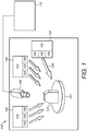
- FIG. 1 shows an imaging system 100 comprising one or more base units 102.
- Each base unit 102 includes the optics and control circuitry 103 for generating red (R), green (G) and blue (B) illumination related to RGB color channels.
- Each base unit 102 comprises corresponding red, green, blue illumination sources 104, 105, 106 which are all independently controllable.
- Illumination sources 104, 105, 106 may produce annular illumination, inverse annular illumination or lateral illumination, for example.
- the imaging system 100 may optionally comprise a holding unit 101 for holding an object 107.
- Illumination sources 104, 105, 106 are located above the object.
- the optical axes of illumination sources 104, 105, 106 are arranged such that they apply illumination in a direction which is non-perpendicular to the object 107.
- the imaging system 100 also includes an image capture device 108, such as a camera, which is directed towards the holding unit 101. Illumination from any combination of illumination sources 104, 105, 106 from any of the base units 102 can be directed towards the object. The image capture device 108 may then capture initial images of any object 107 which has been illuminated.
- an image capture device 108 such as a camera
- annular beam 109 may also illuminate the object 107 and is produced by one of the base units 102.
- the illumination sources 104, 105, 106 may be of any preferred type, such as light emitting diodes (LED) operating at red (R), green (G) and blue (B) frequencies; a simple white light source; an ultra-violet (UV) source or any other appropriate radiation source.
- LED light emitting diodes
- R red
- G green
- B blue
- UV ultra-violet
- the number of light sources in any location can vary from that shown and described herein.
- Each RGB illumination is made up of three LEDs operating at each respective frequency. Alternatively, one LED may produce the RGB illumination. For different illumination sources, there may be different combinations of RGB LEDs. Alternatively, a line or bar of diodes may be arranged to produce one illumination direction.
- control circuitry and optics 103 in each unit 102 which controls the function thereof there may be an overall control system 110 comprising at least a computer, a display unit, processing modules and image enhancing algorithms and any other processes or techniques.
- the control system 110 may be used to control the selection of the illumination sources to be used for specific applications.
- the control system may apply different image enhancing techniques and image processing procedures for different applications.
- Image enhancing techniques are methods and techniques for enhancing the quality of an initial image or for making pertinent information visible for an expert analyzing the content of the image, for example in the biological domain.
- Image processing relates to mathematical operations applied to an image matrix to provide the extraction of information from initial images in order to provide decision support or enable automatic decisions, for example.
- the control system 110 may be used to carry out any other function and/or control operation for the imaging system 100. These include, but are not limited to:
- the aim of the present invention is to propose an improved photometric stereo method for producing an image being a raised relief map also called a raised map of the surface of an object from a plurality of initial images of the object with no knowledge of the properties of the surface of the object and the illumination conditions.
- the image capture device 108 comprises an intensity detection device 112 for selecting each pixel in an image and determining the corresponding pixel value or intensity value I of the pixel.
- the intensity detection device 112 detects or observes the intensity of each pixel in a determined number of images and for each different color channel R, G, B to produce a matrix representing the detected or observed or captured intensity values of all pixels for all the initial images.
- the intensity detection device 112 selects an initial image such as image 1.
- the intensity detection device 112 selects a specific color channel, such as color channel R.
- the intensity detection device 112 detects the pixel value of each pixel in image 1 for color channel R.
- the detected pixel values may refer to IR1(pixel1).
- the intensity detection device 112 proceeds in the same manner with color channels G and B for image 1.
- the detected pixel values may refer, for example, to IG1(pixel1) for color channel G and IB1(pixel 1) for color channel B.
- the intensity detection device 112 then carries out the same steps for images 2 and 3.
- the intensity detection device 112 always selects corresponding pixels in all other initial images to determine the corresponding intensity of the same pixel in all the different initial images.
- the term "same pixel" means that the pixel may be located at the same spatial location in all initial images.
- pixel 1 in image 1 is located at the same place as pixel 1 in images 2 and 3.
- the detected pixel values refer to the following notations, for example when considering pixel1:
- the intensity detection device 112 may store the detected intensities in a corresponding matrix such as matrix IR1 which represents all pixel values for image 1 and associated color channel R.
- the pixel values of all pixels of image 1 associated with color channel G are organized in matrix IG1 and the pixel values of image 1 related to color channel B are arranged in matrix IB1.
- pixel values corresponding to pixels of image 1 are arranged in matrices IR1, IG1 and IB1
- the detected pixel values of all pixels for all images are arranged in corresponding matrices which refer, for example, to:
- the intensity detection device 112 may process an unwrapping step to convert the matrix into a vector comprising a line of data and thus facilitate further calculations based on the pixel values.
- matrix I has a number of rows which is equal to the number of initial images, where an initial image comprises three lines relating to the three color channels.
- Matrix I has a number of columns which is equal to the number of pixels being the same for each initial image.
- the imaging system 100 also comprises a data processor 114 to carry out specific calculations based on pixel values and on a determined mathematical formula.
- the imaging system 100 further comprises a first memory component 116 for storing a database of model components for storing four model components.
- a first model component represents the albedo value of a pixel of an initial image associated with a first matrix A.
- the first matrix A comprises albedo values of pixels, each albedo value relating to the ratio of incident illumination being reflected by each pixel of the surface of the object.
- the albedo value represents an optical property which depends on the material of the surface of the object.
- the first matrix A has a number of rows which is equal to 3 x ni, where each row represents albedo values for all pixels of an initial image for a specific color channel. Thus, three rows represent the three color channels R, G, B.
- the first matrix A comprises a number of columns which is equal to the number of pixels in an initial image.
- a second model component represents the intensity of each illumination source and is associated with a second matrix L.
- the second matrix L is a matrix where each row with a non-null value relates to the intensity value of the illumination source which is unique for each initial image.
- the second matrix L contains a number of rows which is equal to 3 x ni to represent the intensity value for each color channel of each initial image.
- the second matrix L comprises a number of columns which is equal to the value of the number np.
- a third model component V represents the direction of illumination of each illumination source.
- the third model component comprises a third matrix V comprising three components Vx, Vy and Vz related to the orthonormal space (x, y, z).
- a vector (Vx, Vy, Vz) represents the direction of an illumination source during the image acquisition process.
- the third matrix V forces the condition of having only one specific or main illumination direction for all RGB channels for each initial image. For instance, a same illumination source such as a LED may be used for the three color channels R, G, B which all have the same illumination direction for a same image.
- the illumination source then emits a specific wavelength for each color channel .Thus, V T comprises three rows and a number of columns equal to 3 x ni.
- the transpose matrix V T should be used.
- the third model component V is then applied in the functions f and g below with the form of the transpose matrix V T .
- the third matrix V has a number of rows equal to 3 x ni, where a row represents a color channel and, as an initial image is represented with three color channels being R, G and B, an initial image is represented with three rows.
- the third matrix V comprises three columns where each column relates to an axis of the orthonormal space x, y, z.
- a fourth model component represents the position of the three-dimensional normal or 3D normal of a pixel of an image.
- the 3D normal is a vector which is perpendicular to the tangent plane of the pixel.
- the normal or surface orientation relates to a specific property of a surface, such property does not depend on illumination conditions.
- the normal vector is the same in all images.
- the fourth model component is associated with a fourth matrix N.
- the fourth matrix N comprises a number of rows which is equal to 3 related to each axis of the orthonormal space x, y, z.
- the fourth matrix N comprises columns which represent the coordinates of each normal of a pixel in the orthonormal space (x, y, z).
- the fourth matrix N comprises a number of columns which is equal to the number np.
- Figure 3 schematically shows the structure of each matrix, A, L, V and N.
- the mathematical formula (1) may comprise an optional matrix C which is used when considering images of large size with non-uniform illumination conditions.
- initial images relate to images of small size where the distribution of light may be considered to be uniform.
- the mathematical formula to be used does not comprise the optional matrix C and refers to the mathematical formula (1).
- the above mathematical formula (1) may further comprise specific calculation optimizations to avoided increasing computation time due to the high amount of data being processed between all matrices A, N, L and V T for the four model components.
- the data processor 114 further comprises a second memory component 118 for storing a database of structuring components for storing at least three structuring components which optimize calculation.
- the structuring components W adapt the mathematical formula (1) by considering and modeling the physical properties and constraints of the initial images by considering illumination conditions and properties of the surface of the object.
- a second structuring component W L represents a same or identical intensity coefficient for all pixels of the plurality of initial images for each color channel.
- a third structuring component Wv represents the direction of illumination of one illumination source associated with one image from the plurality of initial images for each pixel and for each color channel.
- Wv is as indicated below when considering three initial images.
- W V 1 0 0 1 0 0 1 0 0 0 1 0 0 1 0 0 1 0 0 0 1 0 0 1 0 0 1 0 0 1 0 0 1 0 0 1 0 0 1 0 0 1 0 0 1 0 0 1 0 0 1 0 0 1 0 0 1 0 0 1 0 0 1 0 0 1 0 0 1 0 0 1 0 0 1
- the optimization process is carried out to avoid repetitions of identical rows and columns for each matrix A, L and V and is performed by breaking down each matrix A, L and V into a multiplication of model sub-components, these being matrices A', L' and V' respectively and corresponding structuring components W, these being W A , W V and W L respectively.
- model components are as follows (2):
- Matrices A', V' and L' represent a unique set of data related to pixels for one image.
- Matrices W A , W V and W L respectively provide the coefficient for each matrix A', V' and L' to retrieve the content of matrices A, V and L when computing the multiplications shown in (2).
- the aim of the present invention is to determine the values of the matrices A', L', V' and N to obtain the resulting value for g(A', L', V', N).
- the best resulting value is considered to be that which is as close as possible to the value of I, which represents the intensity value of initial images as taken from the image capture device 108.
- the function f or g has a known result which is equal to the value of I.
- Function g(A', L', V', N) comprises known structuring components which are W A , W L and W V .
- Model components A', L', V' and N must be evaluated to obtain a resulting value for g which is as close as possible to the observed value I.
- Figure 4 schematically shows the structure of each model component A', L', V', N and of the structuring components W A , W L and W V .
- Function g(A', L', V', N) comprising model components A', L', V', N and corresponding structuring components W A , W L and W V is used in the description of the method according to Figure 5 , as an embodiment of the present invention.
- the method according to Figure 5 may also use the function f(A, L, V, N).
- the present invention provides a method for determining the values of A', L', V' or A, L, V and N in a specific manner to minimize the error between the observed intensity I and the corresponding calculated intensity g or f.
- the raised relief map or the representation of the surface of the observed object may then be created by using the obtained matrix N related to the fourth model component.
- the method comprises operating an algorithm based on the steps as shown in Figure 5 .
- the algorithm relates to an alternating optimization which belongs to one of the existing heuristic algorithms which consists in minimizing the objective function by successively setting all variables except one as disclosed in bibliographic references [1], [2] and [3].
- Heuristic principles of alternating optimization are often used for providing blind source separation when one aims at observation matrix factorization into two matrices under certain conditions (e.g., non-negativity).
- the algorithm encompasses the four-component matrix representation and includes additional constraints for each model component.
- the algorithm comprises two sub-minimization procedures as described below and shown in detail in Figure 5 .
- the algorithm comprises a main loop associated with a main loop variable i and a termination condition.
- the termination condition for the main loop comprises a number of iterations n_it of the main loop.
- the number n_it may be equal to 10, for example.
- the main loop comprises inner loops being a first loop and a second loop.
- the first loop is associated with a first loop variable j and the second loop is associated with a second loop variable k.
- step 500 the model components A', L', N of the method are initialized to equal a corresponding determined value A' 0 , L' 0 , N 0 .
- step 502 the value of i representing the main loop variable of the method is initialized to 0.
- step 504 the value of n_it is compared to the main loop variable i to determine if the value of n_it is greater than the value of the main loop variable i.
- step 506 If the value of the number of iteration cycles n_it is greater than the value of the main loop variable i, then the process follows with step 506.
- step 506 the first loop variable j is initialized to 0.
- Steps 510 and 512 below represent a first sub-minimization procedure.
- j ⁇ p is a termination condition for the first minimization method.
- an optimization process such as a minimization operation is applied.
- the minimization operation may comprise the application of a least square minimization technique such as a quadratic loss function.
- a quadratic loss function is applied to obtain the quadratic error between the observed intensity I and the calculated intensity by using the function g.
- the quadratic loss function is based on a variation of the value of the model component V'.
- a specific value of V' is evaluated to provide the minimum difference between the observed intensity I and the function g.
- the model components A', L', N remain unchanged. An evaluated value of V' is determined.
- step 512 the quadratic loss function is similarly based on the variation of the value of the model component N.
- step 512 a specific value of N is determined to provide the minimum difference between the observed intensity I and the function g.
- the model sub-components A', L', V' remain unchanged.
- the value V' corresponds to the evaluated value of V' from step 510.
- An evaluated value of N is determined.
- step 514 the first loop variable j is increased from j to j+1.
- step 508 the increased value of j is compared with the value of p.
- the first loop operates until the value of j is greater than the value of p.
- step 510 operates again in a new iteration of the first loop.
- a new evaluated value of V' is determined by the minimization operation to obtain an optimal evaluated value V' that gives the minimum difference between I and g, wherein g considers the evaluated value of N from step 512 in a previous iteration of the first loop.
- a new evaluated value of N is compared with all previous evaluated values of N of step 512 to determine the evaluated value N that gives the minimum difference between I and g, wherein g considers the evaluated value of V' from step 510 in a previous iteration of the first loop.
- the first loop provides optimal evaluated values for V' and N.
- step 516 the second loop variable k is initialized to 0.
- k ⁇ p is a termination condition.
- Steps 520 and 522 below represent a second sub-minimization procedure.
- k ⁇ p represents a termination condition for the second minimization method.
- step 520 the quadratic loss function applies with the model component L'.
- a specific value of L' is evaluated to provide the minimum difference between the observed intensity I and the function g.
- the model sub-components A', V' and the model component N remain unchanged.
- the values of V' and N correspond to the optimal evaluated values of V' from the first loop which both give the minimum difference between I and g.
- An evaluated value of L' is determined.
- step 522 the quadratic loss function applies with the model component A'.
- a specific value of A' is evaluated to provide the minimum difference between the observed intensity I and the function g.
- the model sub-components L', V' and the model component N remain unchanged.
- the value of L' corresponds to the evaluated value of L' from step 520 and the values of V' and N correspond to the optimal evaluated values of V' and N from the first loop which both give the minimum difference between I and g.
- An evaluated value of A' is determined.
- step 524 the second loop variable k is increased to k+1.
- the second loop operates until the value of k is greater the value of p.
- step 520 operates again in a new iteration of the second loop.
- a new evaluated value of L' is determined by the minimization operation to obtain an optimal evaluated value L' that gives the minimum difference between I and g, wherein g considers the evaluated value of A' from step 520 in a previous iteration of the second loop.
- step 526 When the value of k is greater than the value of p, the method follows with step 526 where the main loop variable i is increased to i+1.
- step 504 to compare the number of loop iterations n_it with the value of the main loop variable i.
- the main loop operates until the number of iteration n_it is lower than the value of the main loop variable i. Where the value of the main loop variable i is greater than the value of the number of repetitions n_it, then the method stops.
- n_it represents a specific termination condition for the present method.
- An alternative termination condition may comprise a threshold value associated with the difference value obtained between the observed intensity I and the calculated intensity f(A, L, V, N) or g(A', L', V', N).
- the method stops when the calculated difference between I and f or I and g is equal to or below the threshold value or a threshold difference value, for example.
- Another alternative termination condition may be based on a threshold difference value.
- the method stops when the difference between two values of a same model component based on two consecutive iterations is equal to or below the threshold value.
- the aim of the method is to consider separately and iteratively for each model component A', L', V' and N the value which gives the minimum difference in the calculation of the quadratic loss function.
- the method is based on main, first and second iterative loops to optimize the determination of the values of the model components A', L', V' and N.
- the aim of the repetition of the main loop, first loop and second loop is to reach the best convergence.
- the data processor 114 operates a comparison step at each iteration of the first and second loops and for each model component.
- the data processor 114 each time the data processor 114 calculates the quadratic loss function to obtain a difference value when increasing a specific model component, the data processor 114 compares the difference value obtained with any existing difference values previously obtained. Thus, the data processor 114 may determine the minimum difference value and retain the minimum difference value for further calculations.
- the value of the number of iterations p is a determined number which may be the same for j and k.
- the first loop relates to model components V and N and the second loop relates to model components A and L for improved optimization of the method.
- Model components V, N relate to interaction between the direction of the surface of the object and the direction of the illumination sources 104, 105, 106. Such interaction determines an angle between these two directions. Calculations related to the determination of such an angle are relatively complex to run due to the size of the corresponding matrices.
- the first loop provides calculations regarding model components V and N or V' and N to optimize calculations and computation time associated with the second loop.
- the second loop provides calculations regarding model components A and L.
- A corresponds to a weighting coefficient associated with the surface of the object.
- L corresponds to a weighting coefficient associated with the illumination source.
- the arrangement of the model components A, L, V, N or A', L', V' N in such a first and second loop provides for better convergence of the method.
- computation time is reduced when compared with a different arrangement of the model components A, L, V, N or A', L', V', N for carrying out the optimization process, such as the minimization operation.
- Alternative arrangements may be: V', N, A', L' or V', L' A', N or V', L', N, A' or V', A', N, L' or V', A', L', N.
- the data processor 114 retrieves the value of N as determined from the method of the present invention.
- the data processor 114 then builds a surface pixel by pixel by considering the value of N for each pixel by applying one of the algorithms disclosed in Bibliographical references [4], [5], [6] and [7].
- the data processor 114 provides a raised relief map of the surface of the considered object.
- Figures 6, 7, 8 and 9 each show an initial image of first objects.
- Figures 10, 11, 12 and 13 show raised relief maps of the surface of the objects of Figures 6, 7, 8 and 9 according to the present invention.
- Figure 14 represents an initial image of an object being a tea bag.
- Figure 15 shows a raised relief map of the object of Figure 14 when considering three initial images of the object shown in Figure 14.
- Figure 16 shows a raised relief map of the object of Figure 14 when considering five initial images of the object shown in Figure 14.
- Figure 17 shows a raised relief map of the object of Figure 14 when considering ten initial images of the object shown in Figure 14 .
- the raised relief map in Figure 17 comprises more details of the object than the raised relief maps in Figures 15 and 16 .
- Visual results of analysis of the surfaces of the raised relief maps indicate an improved quality of the raised relief maps with no significant impact on the general surface aspect when compared to the initial image.
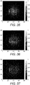
- Figures 18, 19, 20 and 21 show initial images of a first object being a micro-organism.
- Figure 22 shows a top view of the raised relief map of the surface of the object of Figures 18, 19, 20 and 21 .
- Figure 23 represents a side view of the object of Figure 22 .
- Figures 24, 25 , 26 and 27 represent raised relief maps of various objects such as micro-organisms according to the present invention.
- the above described optimization relates to a first embodiment of the present invention method which provides a solution for determining surface normals and for reconstructing the depth map.
- value constraints and quality constraints are not considered during the minimization steps.
- Each model component can be evaluated using least square method.
- values obtained after each sub-minimization can be projected into constraints.
- albedo component A all values of less than zero are equated to zero, and all values greater than one are set to one.
- a similar operation can be performed for light source intensities. Values in the L matrix that are less than zero are set to zero or to a very low value.
- Lighting directions V and surface normals N are only normalized after evaluation of the first minimization loop.
- Supplementary surface normals can be filtered by averaging filter with 3 ⁇ 3 sliding window in order to implement quality smoothness constraint just after normalization.
- Such post-evaluation constraints application is possible due to the iterative nature of the algorithm. Additional steps as described in the second embodiment below and relating to the evaluation of constraints may be provided at the end of the method to provide a first photometric stereo model component approximation.
- the present invention provides a solution for considering value constraints and quality constraints for the photometric stereo model during execution of the optimization method.
- the minimization functions for finding albedo values, light source intensities, light source directions and surface normals matrices take into account supplementary equality and inequality constraints. Minimization operations for each of the model components are described below.
- the light source intensity vector should contain only values greater than 0 and less than the maximum possible value of the image, H .
- the matrix L' shown in Figure 5 should be used with the conditions below:
- Albedo matrix should contain only values from the interval [0; 1].
- minimization function A' i for albedo approximation in Figure 5 should be used with the conditions below:
- Photometric stereo model resolution provides unit normal, i.e. surface, orientation in each pixel.
- Depth maps allow easier visual analysis of the resulting surface than that provided by a normal matrix.
- algorithms presented in Bibliographical references [4], [5], [6] and [7] were tested.
- the integration algorithm presented in [4] turned out to be the fastest and the most efficient for all given examples.
- This algorithm is based on surface partial derivatives representation from two points of view: as discrete derivatives (simple difference between neighbor points) and derivatives calculated on the basis of surface normals. This algorithm was thus used for transition between normals obtained after the alternating optimization and the visualized depth map. In all the following demonstrations, the quality of reconstruction using the depth map is analyzed.
- Figure 28 shows a comparison of the reconstruction results for the simple hemispherical object and for the object from the MIT Intrinsic Images dataset as shown in Bibliographical reference [11].
- the alternating method from Figure 5 was used with 10 global iterations and 5 internal iterations for each minimization.
- the results obtained show the necessity of implementing constraints.
- more complicated surfaces require use of constraints.
- different forms of constraints implementation can be compared with different processing times t: constraints directly integrated into each minimization procedure and projection to the space of constraints after each variable evaluation without constraints.
- step 500 relates to an initialization step based on determined values for A', L' and N.
- Figure 29a relates to an initial image of an object.
- Figure 29b relates to the image based on the matrix of the ground truth normals.
- Figure 29c relates to the image based on the depth map.
- Figure 29d shows a table comprising a plurality of resulting images arranged in a table for comparing the different images based on different initialization criteria for the matrix N. Each initialization criterion relates to a specific row in the table, as described below.
- the first row No relates to initial values of N used at the first step of alternating procedure.
- Nx corresponds to the color channel R of the representation
- Ny corresponds to the color channel G
- Nz corresponds to the color channel B.
- the second row "N" relates to the matrix N as retrieved by the alternating optimization algorithm.
- the second row relates to resulting values of normal encoded in R, G, B channels and obtained with different initializations from row No.
- the third row "SF" relates to the resulting surface of the object which corresponds to the depth map obtained on the basis of the resulting normals from row N.
- the first column "Ones" relates to a unit matrix.
- the second column “Randn” relates to a matrix of normally distributed random values, such as a matrix of values following a Gaussian distribution.
- the third column "Rand” relates to a matrix of uniformly distributed random values.
- the fourth column "3D normals to Med” relates to the matrix comprising different types of initialization for normals. Initial normals equal to 3D normals to each pixel median intensity value. It appears that the algorithm combining the criteria of the fourth column provides the best quality of images.
- Figure 29d contains reconstruction results for different initializations of matrix N.
- the reconstructed surface with initialized normals equal to 3D normals to each pixel median intensity value is significantly better than with other initialized normals.
- albedo matrix A' was chosen as a unit matrix of the appropriate size [3 ⁇ np ] .
- Light source intensities vector L' was taken as a vector of 3ni median values of all images channels.
- Initial matrix N' of surface normal was defined as 3D normal to each pixel median intensity value.
- matrix N' is of required [3 ⁇ np ] size. The described initialization is not the only possible choice but, in combination with the proposed alternating method, has proved to be efficient for obtaining qualitative surfaces.
- the termination condition of the main loop is based on a defined number of iterative loops.
- Alternative termination conditions may comprise a small quadratic error between the initial data and the evaluated variables, and a small variation of variables (or just one, the most important variable) from one iteration to another.
- Figure 30 comprises a table showing three different rows relating to different objects and wherein the first column relates to the ground truth surface, the second column relates to the first termination condition, the third column relates to a second termination condition, and the fourth column relates to a third termination condition and corresponding processing times t. Results show that it is possible to obtain satisfactory surfaces using all of the mentioned criteria.
- the simplest criterion which can be chosen is a number of iterations.
- the number of iterations in the main loop is equal to 10, and the number of iterations in each of the sub-minimizations is 5. For these values, an algorithm convergence was obtained, and the quality of the resulting surfaces is sufficient for further analysis.
- An additional specific image pre-process for improving the quality of initial images may be implemented with the present invention to improve the quality of initial images before applying the method of the present invention on said image that will be used in the present invention.
- Such an additional image pre-process may remove any dark zones or bright zones within initial images, such zones comprising pixel values that may lead to incorrect representation of the deepness map.
- the data processor 114 may calculate specific ratios relating to the comparison between pixel values of pixels in a specific image for different color channels and pixel values of corresponding pixels in other images for corresponding color channels based on the above matrices.
- a ratio of 1 corresponds to the comparison of pixel values of two pixels having the same pixel value.
- the ratio determines a discrepancy between a first pixel value of a pixel in an image and a second pixel value of the same pixel in one or more other images.
- the ratio may be 1.20, representing an increase of 20% of the ratio equal to 1.
- the ratio is lower than 1, this means that the pixel in question corresponds to a darker pixel.
- a ratio comprises, for example, IR1/IR2 to determine the presence of a bright zone in image 1 associated with color channel R when compared with image 2 for the same color channel.
- the resulting ratio values may, for example, be arranged in corresponding matrices of ratios as follows, wherein each vector relates to the ratios of all pixels of image 1, pixel by pixel, and wherein each column of the matrices corresponds to a specific pixel in the related image.
- the data processor 114 iteratively carries out similar ratio calculations to obtain similar ratio matrices for images 2 and 3, and respectively for other color channels G and B for each image 1, 2, and 3 and for each pixel in image 2 and image 3.
- the data processor 114 When considering a multiplicity of N images, the data processor 114 iteratively carries out such ratio calculations for all pixels of all N images for each color channel.
- the data processor 114 may also calculate a weighting value W which is a mean value based on the above obtained ratio matrices.
- the mean value corresponds to a generalized mean value based on a statistical measure.
- the generalized mean aggregates values of a set of data to provide a resulting data value which characterizes or represents the set of data.
- the resulting data value is of the same type as any data value of the set of data.
- the resulting data value is comparable to any data value of the set of data.
- a generalized mean may refer to central tendency measures such as an arithmetic mean (namely an average), a weighted arithmetic mean, a geometric mean, or a median value of the calculated ratios.
- c j is a coefficient allowing to compute weighted means. It may be equal to 1/p in the case of the arithmetic mean, wherein p is the number of reference images; I ref j is the j th image in the plurality of p reference images; I is the image to be corrected.
- the resulting weighting values W may be arranged in corresponding weighting matrices as follows:
- WR1 is a weighting matrix gathering values of W for all pixels of the red channel of image 1.
- the data processor 114 When considering a multiplicity of N images, the data processor 114 iteratively carries out such weight matrix calculations for all pixels of all N images for each color channel.
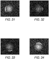
- Figure 38 shows a representation of the ratio WR1 for image 1, as shown in Figure 31 , comprising 6000 pixels being identified with their respective location in image 1.
- the arithmetic mean is used to compute the mean value WR1 based on the three other images being used as reference images as shown in Figure 32, Figure 33 and Figure 34 .
- high values of WR1 correspond to a bright zone located between pixel 1500 to pixel 2000.
- the weighting value W is associated with a threshold value V equal to 1 to compare the weighting value W with the threshold value V to determine in which situation the image associated with the weighting value contains a bright zone.
- the weighting value W is lower than 1 for a specific pixel, this means that the pixel does not relate to a specular pixel.
- the weighting value W may be associated with a specific margin value Vm, such as Vm_high for bright zones and Vm_low for dark zones to define two corresponding threshold intervals.
- Vm_high for bright zones
- Vm_low for dark zones to define two corresponding threshold intervals.
- Such threshold intervals enable specific bright zones and dark zones that may not be related to a specular zone or a shadow zone to be kept in the image. Indeed, such specific bright zones and dark zones may arise due to the interaction of illumination sources with the object caused by specific directions of illumination or the specific nature of the object, for example. Thus, when considering the threshold intervals, such specific zones are not considered as bright zones or dark zones to be corrected with the method of the present invention and remain unchanged in the image.
- Values of Vm_high and Vm_low are defined values such as Vm_high equals 0.2 and Vm_low equals 0.8.
- the first threshold interval relates to the higher values of W that approach the value of 1 and indicate the absence of bright pixels. Based on the value of the margin value Vm_high, the first threshold interval relates to values of V from 1 to V_high, where V_high corresponds to predetermined values of V for bright pixels. In the present example, where Vm_high equals 0.2, the first threshold interval corresponds to values of V from 1 to 1+Vm_high, i.e. 1.2. Thus, when weighting values W are not equal to 1 and are included in the first threshold interval, this implies that related pixels are not considered as comprising any bright pixels corresponding to specular pixels. Thus, pixel values with a high intensity which may be generated by an effect of light due, for example, to the specific nature of the object, are considered for pixel correction but remain almost unchanged after pixel value correction.
- the second threshold interval relates to the lower values of W that approach the value of 0 and indicate the presence of dark pixels. Based on the value of the margin value Vm_low, the second threshold interval corresponds to values of V from V_low to 1, where V_low corresponds to predetermined values of V for dark pixels. In the present example where Vm_low equals 0.8, the second threshold interval corresponds to values of V from 1 to 1-Vm_low i.e. 0.2. Thus, when weighting values W are not equal to 1 and are included in the second threshold interval, this implies that related pixels are not considered as comprising any dark pixels corresponding to a dark zone. Thus, pixel values with a low intensity which may be generated by an effect of light due, for example, to the specific nature of the object or the Petri dish material, are considered for pixel value correction but remain almost unchanged after pixel correction.
- the threshold value V represents a requirement to determine whether pixel value correction with the method of the present pre-process is needed.
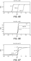
- ⁇ is a parameter defining the sharpness of transition of the sigmoid function. This means that ⁇ may vary to modulate the correction to smooth the visible transition between corrected zones and non-corrected zones of an object in an image as shown in Figure 67 .
- the smoothness of the transition improves the visible effect of the correction on the image and also improves the quality of the image for a process such as a further photometric stereo process for object surface reconstruction.
- Predetermined values of ⁇ for bright pixels and dark pixels may be referred to as ⁇ _high and ⁇ _low respectively.
- f W k _ high 1 + e ⁇ ⁇ _ high W ⁇ V _ high ⁇ k _ low 1 + e ⁇ ⁇ _ low W ⁇ V _ low + k _ low
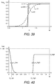
- Figures 39 , 65, 66 and 67 show different embodiments comprising a different set of values for parameters k, f(W), V_high and V_low, and ⁇ .
- the method of the additional pre-process comprises several steps, 1302, 1304, 1306, and 1308, as described below.
- the method comprises step 1302 for the image capture device 108 to acquire a plurality of N images.
- at least two images must be taken with different illumination directions by different illumination sources.
- the intensity detection device 112 considers each different image 1, 2 and 3 and detects the intensity of each pixel for each color channel to obtain the pixel values IR for each pixel, for each image and for each color channel.
- the data processor 114 calculates for a same pixel the ratio between the intensity of the pixel under consideration in an image and the intensity of the corresponding pixel in other images, for a same color channel to obtain the corresponding ratio values.
- the data processor 114 calculates the corresponding mean value of each calculated ratio for each pixel, for each image and each color channel.
- the data processor 114 calculates a corrected pixel value Ic based on the above formula, for each pixel in each image and for each color channel.
- Figures 42, Figure 43, Figure 44 and Figure 45 respectively show a corrected image of the object of Figure 31, Figure 32, Figure 33 and Figure 34 where the bright zone has been corrected in each image using the three other images as reference images for ratio estimation.
- the arithmetic mean has been used as a mean value for calculating W.
- Figures 46, 47 and 48 show the corrected image of Figure 42 in the Red, Green and Blue channels respectively.
- parameter V_high may equal 1.2.
- parameter V_high may equal 1.2 and parameter ⁇ may equal 10 in combination with different values of k.
- Figures 49 to 50 and 52 to 54 refer to images which are stored in a public database as mentioned in A. Hertzmann, S. M.Seitz, "Example-Based Photometric Stereo: Shape Reconstruction with General Varying BRDF", IEEE Transactions on pattern analysis and machine intelligence, vol27, 8, p.1254-1263, 2005 .
- Figure 49 corresponds to one of eight images of an object representing a cat and available in the public database.
- Figures 52, 53 and 54 correspond to three of the fourteen images of an object representing a fish that are available in the public database.
- Figure 49 shows an image of an object representing a cat with a plurality of bright zones.
- Figure 50 shows specific bright zones located around and on the eye of the cat.
- a corrected image as shown in Figure 51 is obtained.
- the method for obtaining the corrected image is carried out by using the other seven images of the cat as reference images.
- the arithmetic mean is used for calculating mean value W and the set of parameters k_high, k_low, V_high, V_low and ⁇ _high and ⁇ _low is the same as the one above mentioned.
- a visual check indicates that bright zones present in the image shown in Figure 50 do not appear in the image shown in Figure 51 .
- a further visual check indicates that the details of Figure 50 representing the eye of the cat have not been altered as a result of applying the method according to the additional pre-process.
- a plurality of bright zones and dark zones can be observed.
- dark zones and bright zones have been removed by applying the method according to the invention.
- the method used for obtaining the corrected image consists of using the other thirteen images of the fish as reference images wherein the thirteen images differ from the image to be corrected.
- the arithmetic mean is used for calculating mean value W and the set of parameters k_high, k_low, V_high, V_low and ⁇ _high and ⁇ _low is the same as the one above mentioned.
- a visual check indicates that the details of the object have not been altered as a result of applying the method according to the additional pre-process.
- Figure 60 shows a graph representing the pixel values or intensity values for the line of pixels of interest for initial image I1 shown in Figure 58 and reference image 12 shown in Figure 59 .
- Figure 61 represents the corrected image I1c of initial image I1 in Figure 58 using reference image I2 on Figure 59 .
- the mean value W is calculated using one reference image shown in Figure 59 .
- the mean value is equal to the ratio of initial image I1 shown in Figure 58 and reference image I2 shown in Figure 59 .
- Figure 62 shows a graph representing the mean value W and the corrected function f(W).
- f(W) is calculated using the same parameters k_high, k_low, V_high, V_low and ⁇ _high and ⁇ _low as above mentioned.
- Figure 62 shows values of f(W) as being not equal to zero, which indicate pixels to be corrected. The values correspond to both bright zones, i.e. relatively high values of W, and dark zones, i.e. relatively low values of W.
- Figure 63 shows a graph representing the pixels values for the line of pixels of interest for initial image I1 shown in Figure 58 and the corrected image I1c shown in Figure 61 .
- Figure 64 shows a graph representing the mean value W estimated as the ratio of initial image I1 shown in Figure 58 and reference image I2 shown in Figure 59 and the corrected mean value Wc estimated as being the ratio of corrected image I1c shown in Figure 61 and reference image I2 shown in Figure 59 .
- the intensity value of bright zones in corrected image I1c is lower than the intensity value of bright zones in image I1 as shown in Figure 60 .
- the intensity value of dark zones in corrected image I1c is higher than the intensity value of dark zones in image I1 as shown in Figure 60 .
- intensity values of pixels characterizing object texture and surface remain unchanged for corrected image I1c in Figure 63 when compared with the intensity value of some pixels in image I1 as shown in Figure 60 .
- an automatic system for adapting the values of the parameters may be implemented.
- each specular zone i.e. bright zone or dark zone, should not totally overlap another specular zone to provide a corrected image of improved quality.
- Figure 87 represents a schematic view of a superimposition of four images of an object 580, wherein image 1 comprises a specular zone 590, image 2 comprises a specular zone 591, image 3 comprises a specular zone 592 and image 4 a comprises specular zone 593. No specular zone overlaps another.
- the method according to the present pre-process provides the best results with specular zones being located as in Figure 87 .
- Figure 88 represents a schematic view of a superimposition of four images of the object 580, wherein image 1 comprises a specular zone 601, image 2 comprises a specular zone 602, image 3 comprises a specular zone 603 and image 4 comprises a specular zone 604. Each of specular zones 601, 602, 603 and 604 partially overlaps at least another specular zone.
- Figure 89 represents a schematic view of a superimposition of four images of the object 580, wherein image 1 comprises a specular zone 611, image 2 a comprises specular zone 612, image 3 comprises a specular zone 613 and image 4 comprises a specular zone 61. At least specular zone 611 totally overlaps specular zones 612, 613 and 614.
- Figure 68 represents an artificial surface of an object captured with different illumination directions.
- Figure 69 represents one of the initial images where correction of a bright zone is required.
- Figure 70 represents an artificial image made of a superimposition of the specular components of seven images corresponding to seven evenly spatially distributed illumination sources.
- Figure 71a represents a corrected image of Figure 69 using seven reference images acquired from seven evenly spatially distributed illumination sources.
- Figure 71b represents the distribution of pixels intensities along the horizontal white line shown in Figure 71a , for the diffuse component in solid line and for the resulting component based on the soft correction in dotted line. As the bright zones are evenly located, the quality of the corrected image is satisfactory. This is shown by the resulting component following the diffuse component on the graph of Figure 43b . In addition, there is no specific impact on zones that do not require correction.
- Figure 72 represents an artificial image made of a superimposition of the specular components of seven images corresponding to seven randomly spatially distributed illumination sources.
- Figure 73a represents a corrected image of Figure 41 using seven reference images acquired from seven randomly spatially distributed illumination sources.
- Figure 73b represents the distribution of pixels intensities along the horizontal white line shown in Figure 73a , for the diffuse component in solid line and for the resulting component based on the soft correction in dotted line.
- the quality of the corrected image is also satisfactory when illumination sources are randomly located.
- Figure 74 represents an artificial image made of a superimposition of the specular components of seven images corresponding to seven closely located illumination sources.
- Figure 75a represents a corrected image of Figure 41 using seven reference images acquired from seven closely located illumination sources.
- Figure 75b represents the distribution of pixels intensities along the horizontal white line shown in Figure 75a , for the diffuse component in solid line and for the resulting component based on the soft correction in dotted line.
- the correction process may not be completed. Indeed, overlapping bright zones may not be detected as being a zone having an incorrect intensity.
- Figure 76 represents the specular component of one image corresponding to an illumination source opposite to the specular zone to be corrected.
- Figure 77a represents a corrected image of Figure 69 using one reference image acquired from one illumination source opposite to the specular zone to be corrected.
- Figure 77b represents the distribution of pixels intensities along the horizontal white line shown in Figure 77a , for the diffuse component in solid line and for the resulting component based on the soft correction in dotted line.
- the corrected image is of good quality, though the general distribution of light on the object surface is not obtained.
- Figure 78 represents an artificial image made of a superimposition of the specular components of ninety-nine images corresponding to ninety-nine randomly spatially distributed illumination sources.
- Figure 79a represents a corrected image of Figure 69 using ninety-nine reference images acquired from ninety-nine randomly spatially distributed illumination sources.
- Figure 79b represents the distribution of pixels intensities along the horizontal white line shown in Figure 79a , for the diffuse component in solid line and for the resulting component based on the soft correction in dotted line.
- the corrected image is of improved quality.
- weighting value W as previously defined applies in an optimal manner and the corrected image is of improved quality.
- weighting value W as previously defined may not correctly detect bright zones or correct such bright zones in an efficient manner.
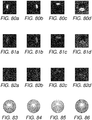
- Figures 80a, 80b, 80c and 80d represent four initial images of a circular object comprising bright zones at different locations without any overlapping zones.
- Figures 81a, 81b, 81c and 81d represent images of the circular object where bright zones have been corrected using an inpainting process well-known in the prior art.
- Figures 82a, 82b, 82c and 82d represent corrected images of the circular object after application of the method of the present invention using soft correction. It appears that corrected images of Figure 82a, 82b, 82c and 82d are of an improved quality when compared with corresponding corrected images 81a, 81b, 81c and 81d obtained with the well-known inpainting process.
- a schematic comparison may be provided to compare prior art processes for removing specular zones on images of an object comprising several circular lines.
- Figure 83 shows a schematic view of contour lines of the surface of the circular object after a surface reconstruction process with no correction of bright zones. It appears that some circular lines are stretched.
- Figure 84 shows a schematic view of contour lines of the surface of the circular object after reconstruction with an inpainting process known in the prior art. It appears that some circular lines are still stretched. The corrected image is of poor quality.
- Figure 85 shows a schematic view of contour lines of the surface of the circular object using the well-known algorithm of Coleman and Jain known in the prior art. Circular lines are stretched and modified in a significant manner. The corrected image is of poor quality.
- the first embodiment above described provides results with enhanced quality in the situation where the user may define the adapted settings for each parameter k, V and ⁇ based on the sets of reference images.
- f(W) now relates to an adaptive correction only based on values of parameter ⁇ .
- I relates to the pixel intensities of the image to be corrected.
- the number of images im_number 1 and can thus be disregarded in further notations.
- each pixel in the image I is referred to as I(p_number).
- image I and images used for correction are assumed to be gray-scaled, i.e. single-channel images. Thus, there is no need to use IR, IG and IB notations.
- Image I is the sole variable representation used in the algorithms.
- a set of p reference images is also used for correcting image I , image ⁇ I ref ⁇ taken from the same fixed camera position and at different light source positions.
- Reference images may correspond to all other images of the initial sequence with the exception of the image to be corrected.
- General light source distribution or location for each image I can be seen as a low frequency component and roughly approximated to an additional plane of intensities. The orientation of the plane and the corresponding translation depends on the position and the intensity of the light source. If the image I has basic shading, then relative shading of each image I ref l , ⁇ l ⁇ 1 p may be represented as a linear approximation, called LinApprox as detailed below, of the matrix of ratio values where ' ⁇ ' relates to the point-to-point division. Thus, when subtracting the approximated plane from the evaluated values of IR_ratio, the general shading is removed. When there is no specular zone, value of this subtraction tends to zero.
- LinApprox I I ref l is an approximation of the matrix of ratio values I p _ number I ref l p _ number by a plane using linear or robust regression coefficients.
- c I denotes weight of image ratios for generalized mean values.
- the coefficients of the linear approximation may be obtained by minimizing the following error: min a 0 , a 1 , a 2 ⁇ I p _ number I ref l p _ number ⁇ a 0 + a 1 x + a 2 y ⁇ 2 2 .
- a0, a1, a2 are the coefficients of the equation defining the approximated plane. Adding one to the residual between ratio value and approximated plane provides a possibility to operate with W as with a simple ratio. The closer the value of W(p_number) is to 1, the less the difference between I(p_number) and I ref l p _ number .
- the approximated plane obtained, LinApprox I I ref l may be seen as a matrix of threshold values appropriate to each pixel (p_number) and for each reference image 1.
- Algorithm 1 and Algorithm 2 related to the first and the second embodiments for providing a corrected image of an object respectively, have the same correction principle.
- the predefined threshold value V was previously included into the correcting function evaluation (line 8, Algorithm 1).
- this value is no longer subtracted (line 12, Algorithm 2) as a result of the operation of linear approximation of the matrix of ratio values IR (line 7, Algorithm 2) and subtraction from the initial matrix of ratio values (line 8, Algorithm 2). This is similar to having a proper threshold value for each image pixel instead of fixed value V for all pixels of the image.
- Image correction is divided into two loops (line 3 - 9, Algorithm 2 and line 10 - 14, Algorithm 2) due to the necessity of identifying all values of the matrix of ratio values IR for the linear approximation S (line 7, Algorithm 2). All other operations, as for Algorithm 1 , remain pixel-related.
- the second embodiment provides results with enhanced quality where the image to be corrected relates to illumination conditions which differ significantly from the illumination conditions of reference images.
- pixel values with a high intensity which may be generated by an effect of light due, for example, to the specific nature of the object, are considered for pixel correction and are less corrected than pixel having pixel values that generates a weighting value W higher than Vm_high.
- pixel values with a low intensity which may be generated by an effect of light due, for example, to the specific nature of the object or the Petri dish, are considered for pixel correction and are less corrected than pixel having pixel values that generates a weighting value W higher than Vm_high.
- the present invention provides a solution for replacing all pixel values of images being processed.
- the present invention provides simultaneous correction of pixel values of specific zones or image regions comprising bright pixels such as specular pixels and dark pixels such as shadow pixels.
- the invention provides a solution for correcting corresponding pixel values in such zones without requiring predetermined information regarding the illumination directions and/or location of illumination sources.
- the invention provides a method based on a multiplicity of images by sequentially considering all pixels in all images. This implies that the pixel information from all images is used to provide correction to any pixel being associated with a specular pixel or shadow pixel.
- the invention allows pixel values of specific zones comprising specific information associated with the image regarding a specific illumination direction to remain unchanged.
- Pixel values of the specific zones may relate to shading information of the related image.
- all pixels in the images are taken into consideration and merged to provide replacement and also correction of pixel values.
- This aspect allows the orientation of the surface of the object to be reliably estimated when processing the photometric stereo method, for example, in a further step of the method.
- the processing of the further photometric stereo method is also improved as the present invention provides a multiplicity of corrected images based on the multiplicity of initial images.
- a minimum of two images of the object are necessary to correct pixel values of only one image of the object if no further surface reconstruction process is required.
- the present pre-process is suitable for restoring highlighted and shadowed zones of images even when considering zones of substantial size and comprising complex pixel texture.
- a significant number of images may be used and a significant number of illumination sources may be located evenly around the object.
- an increased amount of information related to pixel values of the object can be considered.
- the correction of pixel values may be improved.
- a zone of interest must not totally overlap another zone of interest in all other images.
- the method of the present pre-process applies in an optimal manner to images related to specular hemispheric objects such as images of micro-organisms.
Landscapes
- Engineering & Computer Science (AREA)
- Physics & Mathematics (AREA)
- General Physics & Mathematics (AREA)
- Theoretical Computer Science (AREA)
- Computer Vision & Pattern Recognition (AREA)
- Computer Graphics (AREA)
- Multimedia (AREA)
- Signal Processing (AREA)
- Image Processing (AREA)
- Image Analysis (AREA)
- Length Measuring Devices By Optical Means (AREA)
- Investigating Or Analysing Materials By Optical Means (AREA)
Claims (15)
- Un procédé pour l'obtention d'un modèle d'une surface d'objet à partir d'une pluralité d'images dudit objet (107), où l'objet (107) est éclairé par une ou plusieurs sources d'éclairage (104, 105, 106), le procédé comprenant :- l'obtention d'un ensemble d'images comprenant chacune un réseau de pixels et représentant des mêmes vues d'un objet, où les mêmes vues sont obtenues dans des conditions d'éclairage différentes ;- la définition d'une fonction de modèle (f) qui exprime les valeurs d'intensité de pixels connues des images en termes des composantes de modèle inconnues suivantes :- une première composante de modèle (A) représentant l'albédo de l'objet (107) au niveau de chaque emplacement de pixel, la première composante de modèle étant une valeur d'albédo qui est la même pour la pluralité d'images ;- une deuxième composante de modèle (L) représentant une intensité d'éclairage pour chaque image, la deuxième composante de modèle étant une valeur d'intensité de source d'éclairage qui est la même pour tous les pixels de chaque image ;- une troisième composante de modèle (V) représentant une direction d'éclairage spécifique, la troisième composante de modèle étant un vecteur d'éclairage qui est différent pour chaque image et le même pour tous les pixels de chaque image ;- une quatrième composante de modèle (N) représentant des directions normales de surface de la surface d'objet au niveau de chaque position de pixel, la quatrième composante de modèle étant un vecteur normal qui est le même pour toutes les images ;- la mise en œuvre de plus de séquences d'opérations de minimisation afin de minimiser une fonction de différence entre les valeurs de pixel obtenues à partir de l'ensemble d'images et des valeurs de pixel calculées à l'aide de ladite fonction de modèle (f), chaque opération de minimisation étant mise en œuvre en permettant à l'une desdites composantes de modèle (A, L, V, N) de varier tandis que les autres restent inchangées ;- la production en sortie de la quatrième composante de modèle (N) en tant que ledit modèle de la surface d'objet ;où ladite séquence d'opérations de minimisation comprend une boucle itérative dans laquelle chacune desdites composantes de modèle (A, L, V, N) est amenée à varier à son tour au moins une fois avant une itération ultérieure, ladite boucle itérative étant répétée jusqu'à ce qu'une condition de terminaison soit rencontrée, et
où ladite boucle itérative comprend une première boucle interne et une deuxième boucle interne
et où la première boucle interne comprend cinq itérations, grâce à quoi chacune des itérations de la première boucle interne comprend une opération de la séquence d'opérations de minimisation basée sur une variation de la troisième composante de modèle (V) suivie par une opération de la séquence d'opérations de minimisation basée sur une variation de la quatrième composante de modèle (N),
où la première boucle interne est suivie par la deuxième boucle interne et la deuxième boucle interne comprend cinq itérations, grâce à quoi chacune des itérations de la deuxième boucle interne comprend une opération de la séquence d'opérations de minimisation basée sur une variation de la deuxième composante de modèle (L) suivie par une opération de la séquence d'opérations de minimisation basée sur une variation de la première composante de modèle. - Le procédé tel que revendiqué dans n'importe quelles revendications précédentes, où la première composante de modèle (A) comprend une matrice de sous-composante de modèle (A') et une matrice de première composante structurante (WA), où la matrice de première composante structurante (WA) adapte la matrice de première sous-composante de modèle (A') afin de reproduire les propriétés de surface de l'objet (107).
- Le procédé tel que revendiqué dans n'importe quelles revendications précédentes, où la deuxième composante de modèle (L) comprend une matrice de deuxième sous-composante de modèle (L') et un vecteur de deuxième composante structurante (WL), où la matrice de deuxième composante structurante (WL) adapte la matrice de deuxième sous-composante de modèle (L') afin de reproduire les conditions d'éclairage des sources d'éclairage (104, 105, 106).
- Le procédé tel que revendiqué dans n'importe quelles revendications précédentes, où la troisième composante de modèle (V) comprend une matrice de troisième sous-composante de modèle (V') et une matrice de troisième composante structurante (WV), où la matrice de troisième composante structurante (WV) adapte la matrice de troisième sous-composante de modèle (V') afin de reproduire les conditions d'éclairage des sources d'éclairage (104, 105, 106).
- Le procédé tel que revendiqué dans la revendication 2, où la matrice de première composante structurante (WA) représente un coefficient pour la pluralité d'images comprenant la même valeur d'albédo pour chaque pixel pour la pluralité d'images.
- Le procédé tel que revendiqué dans la revendication 3, où le vecteur de deuxième composante structurante (WL) représente un même coefficient d'intensité pour tous les pixels d'une image parmi la pluralité d'images.
- Le procédé tel que revendiqué dans la revendication 4, où la matrice de troisième composante structurante (WV) représente la direction d'éclairage d'une source d'éclairage (104, 105, 106) associée à une image de ladite pluralité d'images, celle-ci étant la même pour tous les pixels d'une image parmi la pluralité d'images.
- Le procédé tel que revendiqué dans n'importe quelles revendications précédentes, où les une ou plusieurs sources d'éclairage (104, 105, 106) comprennent des canaux de couleur Rouge, Vert et Bleu.
- Le procédé tel que revendiqué dans la revendication 8, où la première composante de modèle (A) est la même pour chaque pixel et chaque canal de couleur pour la pluralité d'images et la deuxième composante de modèle (L) est la même pour chaque canal de couleur pour tous les pixels de chaque image.
- Le procédé tel que revendiqué dans la revendication 8, où la matrice de première composante structurante (WA) comprend la même valeur d'albédo pour chaque pixel pour un même canal de couleur pour la pluralité d'images.
- Le procédé tel que revendiqué dans la revendication 8, où le vecteur de deuxième composante structurante (WL) représente un même coefficient d'intensité pour un même canal de couleur pour tous les pixels de chaque image.
- Le procédé tel que revendiqué dans n'importe lesquelles des revendications 2 à 7, où la fonction de modèle (f) comprend une fonction de modèle modifiée (g), où la fonction de modèle (f) liée aux première, deuxième, troisième et quatrième composantes de modèle (A, L, V, N) est égale à la fonction de modèle modifiée (g) liée aux matrices de première, deuxième et troisième sous-composantes de modèle (A', L', V') et à la quatrième composante de modèle (N).
- Un produit-programme informatique comprenant des instructions qui lorsqu'elles sont exécutées amènent un appareil de traitement de données programmables à mettre en œuvre des étapes du procédé selon les revendications 1 à 12.
- Un système d'imagerie (100) pour l'obtention d'un modèle d'une surface d'objet à partir d'une pluralité d'images dudit objet (107), le système d'imagerie (100) comprenant :- une ou plusieurs sources d'éclairage (104, 105, 106) afin d'éclairer l'objet (107) avec des directions d'éclairage différentes, où chaque image est associée à une direction d'éclairage déterminée ;- un dispositif de capture d'image (108) pour la détection des valeurs de pixel de chaque pixel dans chaque image de la pluralité d'images ;- un processeur de données (114) comprenant un premier composant de mémoire (116) pour le stockage des composantes de modèle inconnues suivantes :où le processeur de données (114) est conçu pour mettre en œuvre plus de séquences d'opérations de minimisation afin de minimiser une fonction de différence entre les valeurs de pixel reçues sur l'ensemble d'images et des valeurs de pixel calculées à l'aide d'une fonction de modèle définie (f) qui exprime les valeurs de pixel connues d'images en termes des composantes de modèle inconnues ;- une première composante de modèle (A) représentant l'albédo de l'objet (107) au niveau de chaque emplacement de pixel, la première composante de modèle étant une valeur d'albédo qui est la même pour la pluralité d'images ;- une deuxième composante de modèle (L) représentant une intensité d'éclairage pour chaque image, la deuxième composante de modèle étant une valeur d'intensité de source d'éclairage qui est la même pour tous les pixels de chaque image ;- une troisième composante de modèle (V) représentant une direction d'éclairage spécifique, la troisième composante de modèle étant un vecteur d'éclairage qui est différent pour chaque image et le même pour tous les pixels de chaque image ;- une quatrième composante de modèle (N) représentant des directions normales de surface de la surface d'objet au niveau de chaque position de pixel, la quatrième composante de modèle étant un vecteur normal qui est le même pour toutes les images ;
et où ladite séquence d'opérations de minimisation comprend une boucle itérative et est mise en œuvre en permettant à l'une desdites composantes de modèle (A, L, V, N) de varier tandis que les autres composantes de modèle restent fixes, ladite boucle itérative étant répétée jusqu'à ce qu'une condition de terminaison soit rencontrée, et
pour la production en sortie de la composante de modèle normale (N) en tant que ledit modèle de la surface d'objet, et
où ladite boucle itérative comprend une première boucle interne et une deuxième boucle interne,
et où la première boucle interne comprend cinq itérations, grâce à quoi chacune des itérations de la première boucle interne comprend une opération de la séquence d'opérations de minimisation basée sur une variation de la troisième composante de modèle (V) suivie par une opération de la séquence d'opérations de minimisation basée sur une variation de la quatrième composante de modèle (N),
où la première boucle interne est suivie par la deuxième boucle interne et la deuxième boucle interne comprend cinq itérations, grâce à quoi chacune des itérations de la deuxième boucle interne comprend une opération de la séquence d'opérations de minimisation basée sur une variation de la deuxième composante de modèle (L) suivie par une opération de la séquence d'opérations de minimisation basée sur une variation de la première composante de modèle. - Un système d'imagerie (100) tel que revendiqué dans la revendication 14, où le processeur de données (114) comprend en outre un deuxième composant de mémoire (118) pour le stockage de matrices de composantes structurantes (WA, WV) afin d'adapter une ou plusieurs matrices des matrices de sous-composantes de modèle (A', L', V') afin de reproduire les propriétés de surface de l'objet (107) et les conditions d'éclairage des sources d'éclairage (104, 105, 106).
Priority Applications (1)
| Application Number | Priority Date | Filing Date | Title |
|---|---|---|---|
| EP14730444.8A EP3000100B1 (fr) | 2013-05-23 | 2014-05-22 | Procédé, système et produit de programme informatique permettant d'améliorer la qualité d'une image |
Applications Claiming Priority (5)
| Application Number | Priority Date | Filing Date | Title |
|---|---|---|---|
| EP13305673.9A EP2806394A1 (fr) | 2013-05-23 | 2013-05-23 | Procédé, système et produit de programme informatique permettant d'améliorer la qualité d'une image |
| EP13305672.1A EP2806399A1 (fr) | 2013-05-23 | 2013-05-23 | Procédé, système et produit de programme informatique permettant de produire une carte en relief à partir d'images d'un objet |
| EP13180149 | 2013-08-12 | ||
| PCT/EP2014/060582 WO2014187919A1 (fr) | 2013-05-23 | 2014-05-22 | Procédé, système et produit de programme d'ordinateur pour produire une carte en relief surélevé à partir d'images d'un objet |
| EP14730444.8A EP3000100B1 (fr) | 2013-05-23 | 2014-05-22 | Procédé, système et produit de programme informatique permettant d'améliorer la qualité d'une image |
Publications (2)
| Publication Number | Publication Date |
|---|---|
| EP3000100A1 EP3000100A1 (fr) | 2016-03-30 |
| EP3000100B1 true EP3000100B1 (fr) | 2019-11-27 |
Family
ID=50792445
Family Applications (2)
| Application Number | Title | Priority Date | Filing Date |
|---|---|---|---|
| EP14730444.8A Active EP3000100B1 (fr) | 2013-05-23 | 2014-05-22 | Procédé, système et produit de programme informatique permettant d'améliorer la qualité d'une image |
| EP14726139.0A Not-in-force EP3000098B1 (fr) | 2013-05-23 | 2014-05-22 | Procédé, système et produit de programme informatique permettant d'améliorer la qualité d'une image |
Family Applications After (1)
| Application Number | Title | Priority Date | Filing Date |
|---|---|---|---|
| EP14726139.0A Not-in-force EP3000098B1 (fr) | 2013-05-23 | 2014-05-22 | Procédé, système et produit de programme informatique permettant d'améliorer la qualité d'une image |
Country Status (6)
| Country | Link |
|---|---|
| US (2) | US10007995B2 (fr) |
| EP (2) | EP3000100B1 (fr) |
| JP (2) | JP6371835B2 (fr) |
| CN (2) | CN105453135B (fr) |
| AU (2) | AU2014270403B2 (fr) |
| WO (2) | WO2014187917A1 (fr) |
Families Citing this family (24)
| Publication number | Priority date | Publication date | Assignee | Title |
|---|---|---|---|---|
| US10860683B2 (en) | 2012-10-25 | 2020-12-08 | The Research Foundation For The State University Of New York | Pattern change discovery between high dimensional data sets |
| EP3000100B1 (fr) * | 2013-05-23 | 2019-11-27 | bioMérieux | Procédé, système et produit de programme informatique permettant d'améliorer la qualité d'une image |
| CN105960586B (zh) | 2014-01-30 | 2020-03-03 | Bd科斯特公司 | 用于使用监督式高品质成像的图像采集的系统和方法 |
| JP6424020B2 (ja) | 2014-06-09 | 2018-11-14 | 株式会社キーエンス | 画像検査装置、画像検査方法、画像検査プログラム及びコンピュータで読み取り可能な記録媒体並びに記録した機器 |
| FR3034233B1 (fr) * | 2015-03-25 | 2018-08-10 | Morpho | Procede de correction d'une image d'au moins un objet presente a distance devant un imageur et eclaire par un systeme d'eclairage et systeme de prise de vues pour la mise en œuvre dudit procede |
| WO2016172532A2 (fr) | 2015-04-23 | 2016-10-27 | Bd Kiestra B.V. | Procédé et système pour le comptage automatisé de colonies microbiennes à partir d'un échantillon strié sur des supports plaqués |
| EP3286731B1 (fr) | 2015-04-23 | 2020-09-16 | BD Kiestra B.V. | Collecte de colonies par contraste |
| GB2545394A (en) * | 2015-11-27 | 2017-06-21 | Fuel 3D Tech Ltd | Systems and methods for forming three-dimensional models of objects |
| CN109564701A (zh) * | 2016-07-18 | 2019-04-02 | 巴塞尔大学 | 用于改善数字图像中光泽表示的计算机系统和方法 |
| CN106570850B (zh) * | 2016-10-12 | 2019-06-04 | 成都西纬科技有限公司 | 一种图像融合方法 |
| US10410735B1 (en) * | 2017-02-23 | 2019-09-10 | Pdf Solutions, Inc. | Direct access memory characterization vehicle |
| CN107451998B (zh) * | 2017-08-08 | 2020-11-06 | 北京大恒普信医疗技术有限公司 | 一种眼底图像质量控制方法 |
| EP3460753A1 (fr) | 2017-09-21 | 2019-03-27 | Infaimon, SL | Système stéréo photométrique et procédé d'inspection d'objets à l'aide d'une caméra à une prise et programme informatique |
| CN107577246B (zh) * | 2017-09-29 | 2020-08-07 | 深圳市富斯科技有限公司 | 一种图像拍摄方法、系统以及电子云台和飞行器 |
| CN108416782B (zh) * | 2018-04-19 | 2023-09-26 | 云南佳叶现代农业发展有限公司 | 基于视觉识别和光照矫正的烟叶评级方法及系统 |
| DE102018208739A1 (de) * | 2018-06-04 | 2019-12-05 | Conti Temic Microelectronic Gmbh | Abschätzung von Ortskoordinaten von Lichtquellen in Umgebungsbildern |
| CN111751332B (zh) * | 2019-03-28 | 2025-05-16 | 易孛特生命科学(上海)有限公司 | 生物样品膜上的自发光物体的成像方法及装置 |
| CN113496450B (zh) * | 2020-03-20 | 2025-03-07 | 阿里巴巴集团控股有限公司 | 数据处理方法、装置及设备 |
| JP7310750B2 (ja) * | 2020-08-07 | 2023-07-19 | トヨタ自動車株式会社 | 色味補正システム及び色味補正方法 |
| CN113126944B (zh) * | 2021-05-17 | 2021-11-09 | 北京的卢深视科技有限公司 | 深度图的显示方法、显示装置、电子设备及存储介质 |
| CN113744169A (zh) * | 2021-09-07 | 2021-12-03 | 讯飞智元信息科技有限公司 | 图像增强方法、装置、电子设备和存储介质 |
| CN115035306B (zh) * | 2022-06-24 | 2025-04-11 | Oppo广东移动通信有限公司 | 图像材质确定方法及相关装置 |
| CN116245741B (zh) * | 2022-06-28 | 2023-11-17 | 荣耀终端有限公司 | 图像处理方法及其相关设备 |
| CN115661349B (zh) * | 2022-10-26 | 2023-10-27 | 中国农业大学 | 基于样本图像的三维重建方法、系统、设备、介质及产品 |
Family Cites Families (20)
| Publication number | Priority date | Publication date | Assignee | Title |
|---|---|---|---|---|
| JPH0793535A (ja) * | 1993-09-22 | 1995-04-07 | Fanuc Ltd | 画像修正処理方法 |
| US5852675A (en) * | 1995-04-14 | 1998-12-22 | Kiyoshi Matsuo | Color chart for image correction and method of color correction |
| US6088612A (en) * | 1997-04-04 | 2000-07-11 | Medtech Research Corporation | Method and apparatus for reflective glare removal in digital photography useful in cervical cancer detection |
| US6088470A (en) * | 1998-01-27 | 2000-07-11 | Sensar, Inc. | Method and apparatus for removal of bright or dark spots by the fusion of multiple images |
| US6674917B1 (en) * | 1998-09-29 | 2004-01-06 | Hitachi, Ltd. | Method of synthesizing an image for any light source position and apparatus therefor |
| US6341016B1 (en) * | 1999-08-06 | 2002-01-22 | Michael Malione | Method and apparatus for measuring three-dimensional shape of object |
| US6853745B1 (en) * | 2000-11-03 | 2005-02-08 | Nec Laboratories America, Inc. | Lambertian reflectance and linear subspaces |
| US6819805B2 (en) * | 2001-05-02 | 2004-11-16 | Agilent Technologies, Inc. | Method and apparatus for brightness equalization of images taken with point source illumination |
| CA2521857C (fr) * | 2003-04-07 | 2012-06-12 | E.I. Du Pont De Nemours And Company | Procede et appareil de quantification de la presentation visuelle d'images imprimees sur l'envers d'objets planaires |
| FR2860089B1 (fr) | 2003-09-23 | 2005-11-11 | Do Labs | Procede et systeme pour modifier une image numerique de maniere differenciee et quasi reguliere par pixel |
| JP4161910B2 (ja) * | 2004-01-28 | 2008-10-08 | 株式会社デンソー | 距離画像データ生成装置及び生成方法,プログラム |
| US7319467B2 (en) * | 2005-03-29 | 2008-01-15 | Mitsubishi Electric Research Laboratories, Inc. | Skin reflectance model for representing and rendering faces |
| JP2007206797A (ja) * | 2006-01-31 | 2007-08-16 | Omron Corp | 画像処理方法および画像処理装置 |
| US8537229B2 (en) * | 2008-04-10 | 2013-09-17 | Hankuk University of Foreign Studies Research and Industry—University Cooperation Foundation | Image reconstruction |
| JP5423379B2 (ja) * | 2009-08-31 | 2014-02-19 | ソニー株式会社 | 画像処理装置および画像処理方法、並びにプログラム |
| EP2520923A1 (fr) | 2011-05-06 | 2012-11-07 | bioMérieux | Bio-imaging method and system |
| GB2490872B (en) * | 2011-05-09 | 2015-07-29 | Toshiba Res Europ Ltd | Methods and systems for capturing 3d surface geometry |
| CN102692814B (zh) * | 2012-06-18 | 2013-09-11 | 北京理工大学 | 一种基于Abbe矢量成像模型的光源-掩模混合优化方法 |
| EP3000100B1 (fr) * | 2013-05-23 | 2019-11-27 | bioMérieux | Procédé, système et produit de programme informatique permettant d'améliorer la qualité d'une image |
| US9396544B2 (en) * | 2014-01-08 | 2016-07-19 | Adobe Systems Corporation | Single image photometric stereo for colored objects |
-
2014
- 2014-05-22 EP EP14730444.8A patent/EP3000100B1/fr active Active
- 2014-05-22 CN CN201480029777.9A patent/CN105453135B/zh not_active Expired - Fee Related
- 2014-05-22 CN CN201480029849.XA patent/CN105474261B/zh not_active Expired - Fee Related
- 2014-05-22 AU AU2014270403A patent/AU2014270403B2/en not_active Ceased
- 2014-05-22 AU AU2014270405A patent/AU2014270405B2/en not_active Ceased
- 2014-05-22 WO PCT/EP2014/060579 patent/WO2014187917A1/fr not_active Ceased
- 2014-05-22 EP EP14726139.0A patent/EP3000098B1/fr not_active Not-in-force
- 2014-05-22 JP JP2016514417A patent/JP6371835B2/ja not_active Expired - Fee Related
- 2014-05-22 US US14/892,826 patent/US10007995B2/en active Active
- 2014-05-22 US US14/892,848 patent/US9710914B2/en not_active Expired - Fee Related
- 2014-05-22 JP JP2016514419A patent/JP6454328B2/ja not_active Expired - Fee Related
- 2014-05-22 WO PCT/EP2014/060582 patent/WO2014187919A1/fr not_active Ceased
Non-Patent Citations (1)
| Title |
|---|
| None * |
Also Published As
| Publication number | Publication date |
|---|---|
| WO2014187919A1 (fr) | 2014-11-27 |
| EP3000098A1 (fr) | 2016-03-30 |
| AU2014270405A1 (en) | 2015-11-26 |
| CN105453135A (zh) | 2016-03-30 |
| WO2014187917A1 (fr) | 2014-11-27 |
| AU2014270403B2 (en) | 2018-07-05 |
| US9710914B2 (en) | 2017-07-18 |
| CN105474261B (zh) | 2018-11-27 |
| AU2014270405B2 (en) | 2018-10-04 |
| EP3000098B1 (fr) | 2018-08-29 |
| US20160098840A1 (en) | 2016-04-07 |
| US20160093033A1 (en) | 2016-03-31 |
| CN105453135B (zh) | 2018-11-20 |
| EP3000100A1 (fr) | 2016-03-30 |
| AU2014270403A1 (en) | 2015-11-26 |
| JP6371835B2 (ja) | 2018-08-08 |
| US10007995B2 (en) | 2018-06-26 |
| JP2016527591A (ja) | 2016-09-08 |
| JP6454328B2 (ja) | 2019-01-16 |
| CN105474261A (zh) | 2016-04-06 |
| JP2016526214A (ja) | 2016-09-01 |
Similar Documents
| Publication | Publication Date | Title |
|---|---|---|
| EP3000100B1 (fr) | Procédé, système et produit de programme informatique permettant d'améliorer la qualité d'une image | |
| US11452455B2 (en) | Skin reflectance and oiliness measurement | |
| CN110383805B (zh) | 用于捕获被测对象的测量图像的方法和系统 | |
| CN102308306B (zh) | 用于图像分离的约束生成器 | |
| US9053537B2 (en) | Classifier for use in generating a diffuse image | |
| JP6872566B2 (ja) | 細菌のグラムタイプを特定するためのプロセス及びシステム | |
| CN116148265A (zh) | 一种基于合成革高质量图像获取的瑕疵分析方法及系统 | |
| US9760799B2 (en) | Pipeline for generating an intrinsic image | |
| CN109191434A (zh) | 一种细胞分化中的图像检测系统及检测方法 | |
| US6577775B1 (en) | Methods and apparatuses for normalizing the intensity of an image | |
| EP3580725B1 (fr) | Procédé de mise en correspondance de couleurs | |
| CN113744154A (zh) | 基于高光谱成像的纤维图像高光检测与消除方法 | |
| EP2776979B1 (fr) | Post-traitement pour génération améliorée d'images intrinsèques | |
| CN117934966A (zh) | 一种配色融合规划的烤瓷义齿自动调色系统 | |
| EP2806399A1 (fr) | Procédé, système et produit de programme informatique permettant de produire une carte en relief à partir d'images d'un objet | |
| Vlachos et al. | The Impact of a Deep Learning Self-Adaptive Colour Restoration Pipeline for Deep Underwater Images in 3D Reconstruction | |
| EP2806394A1 (fr) | Procédé, système et produit de programme informatique permettant d'améliorer la qualité d'une image | |
| Nohira et al. | Texture statistics involved in specular highlight exclusion for object lightness perception | |
| CN112425865B (zh) | 生成鞋楦以及评估鞋楦舒适度的方法、装置及系统 | |
| CN119246527A (zh) | 基于快速空间频域成像技术的大豆种子质量检测方法 | |
| Gui | Aspects regarding the use of image processing for tangible Cultural Heritage conservation-restoration | |
| CN121942007A (zh) | 用于减小全局和局部光照变化下的图像可变性的方法 | |
| CN121169774A (zh) | 基于人工智能算法的图像处理方法、装置和计算机设备 | |
| CN118982717A (zh) | 一种基于反光区均匀化的金属保温杯杯壁异常检测方法及系统 | |
| NO338098B1 (no) | Bildeutjevning |
Legal Events
| Date | Code | Title | Description |
|---|---|---|---|
| PUAI | Public reference made under article 153(3) epc to a published international application that has entered the european phase |
Free format text: ORIGINAL CODE: 0009012 |
|
| 17P | Request for examination filed |
Effective date: 20151113 |
|
| AK | Designated contracting states |
Kind code of ref document: A1 Designated state(s): AL AT BE BG CH CY CZ DE DK EE ES FI FR GB GR HR HU IE IS IT LI LT LU LV MC MK MT NL NO PL PT RO RS SE SI SK SM TR |
|
| AX | Request for extension of the european patent |
Extension state: BA ME |
|
| RIN1 | Information on inventor provided before grant (corrected) |
Inventor name: KYRGYZOVA, KHRYSTYNA Inventor name: ALLANO, LORENE |
|
| DAX | Request for extension of the european patent (deleted) | ||
| STAA | Information on the status of an ep patent application or granted ep patent |
Free format text: STATUS: EXAMINATION IS IN PROGRESS |
|
| 17Q | First examination report despatched |
Effective date: 20170825 |
|
| REG | Reference to a national code |
Ref country code: DE Ref legal event code: R079 Ref document number: 602014057469 Country of ref document: DE Free format text: PREVIOUS MAIN CLASS: G06T0007000000 Ipc: G06T0007586000 |
|
| GRAP | Despatch of communication of intention to grant a patent |
Free format text: ORIGINAL CODE: EPIDOSNIGR1 |
|
| STAA | Information on the status of an ep patent application or granted ep patent |
Free format text: STATUS: GRANT OF PATENT IS INTENDED |
|
| RIC1 | Information provided on ipc code assigned before grant |
Ipc: G06T 7/586 20170101AFI20190524BHEP Ipc: G06T 5/50 20060101ALI20190524BHEP |
|
| INTG | Intention to grant announced |
Effective date: 20190702 |
|
| RAP1 | Party data changed (applicant data changed or rights of an application transferred) |
Owner name: BIOMERIEUX Owner name: COMMISSARIAT A L'ENERGIE ATOMIQUE ET AUX ENERGIES |
|
| RAP1 | Party data changed (applicant data changed or rights of an application transferred) |
Owner name: BIOMERIEUX |
|
| GRAS | Grant fee paid |
Free format text: ORIGINAL CODE: EPIDOSNIGR3 |
|
| GRAA | (expected) grant |
Free format text: ORIGINAL CODE: 0009210 |
|
| STAA | Information on the status of an ep patent application or granted ep patent |
Free format text: STATUS: THE PATENT HAS BEEN GRANTED |
|
| AK | Designated contracting states |
Kind code of ref document: B1 Designated state(s): AL AT BE BG CH CY CZ DE DK EE ES FI FR GB GR HR HU IE IS IT LI LT LU LV MC MK MT NL NO PL PT RO RS SE SI SK SM TR |
|
| REG | Reference to a national code |
Ref country code: GB Ref legal event code: FG4D |
|
| REG | Reference to a national code |
Ref country code: CH Ref legal event code: EP |
|
| REG | Reference to a national code |
Ref country code: AT Ref legal event code: REF Ref document number: 1207554 Country of ref document: AT Kind code of ref document: T Effective date: 20191215 |
|
| REG | Reference to a national code |
Ref country code: DE Ref legal event code: R096 Ref document number: 602014057469 Country of ref document: DE |
|
| REG | Reference to a national code |
Ref country code: IE Ref legal event code: FG4D |
|
| REG | Reference to a national code |
Ref country code: NL Ref legal event code: MP Effective date: 20191127 |
|
| REG | Reference to a national code |
Ref country code: LT Ref legal event code: MG4D |
|
| PG25 | Lapsed in a contracting state [announced via postgrant information from national office to epo] |
Ref country code: FI Free format text: LAPSE BECAUSE OF FAILURE TO SUBMIT A TRANSLATION OF THE DESCRIPTION OR TO PAY THE FEE WITHIN THE PRESCRIBED TIME-LIMIT Effective date: 20191127 Ref country code: BG Free format text: LAPSE BECAUSE OF FAILURE TO SUBMIT A TRANSLATION OF THE DESCRIPTION OR TO PAY THE FEE WITHIN THE PRESCRIBED TIME-LIMIT Effective date: 20200227 Ref country code: LT Free format text: LAPSE BECAUSE OF FAILURE TO SUBMIT A TRANSLATION OF THE DESCRIPTION OR TO PAY THE FEE WITHIN THE PRESCRIBED TIME-LIMIT Effective date: 20191127 Ref country code: GR Free format text: LAPSE BECAUSE OF FAILURE TO SUBMIT A TRANSLATION OF THE DESCRIPTION OR TO PAY THE FEE WITHIN THE PRESCRIBED TIME-LIMIT Effective date: 20200228 Ref country code: NO Free format text: LAPSE BECAUSE OF FAILURE TO SUBMIT A TRANSLATION OF THE DESCRIPTION OR TO PAY THE FEE WITHIN THE PRESCRIBED TIME-LIMIT Effective date: 20200227 Ref country code: SE Free format text: LAPSE BECAUSE OF FAILURE TO SUBMIT A TRANSLATION OF THE DESCRIPTION OR TO PAY THE FEE WITHIN THE PRESCRIBED TIME-LIMIT Effective date: 20191127 Ref country code: LV Free format text: LAPSE BECAUSE OF FAILURE TO SUBMIT A TRANSLATION OF THE DESCRIPTION OR TO PAY THE FEE WITHIN THE PRESCRIBED TIME-LIMIT Effective date: 20191127 Ref country code: NL Free format text: LAPSE BECAUSE OF FAILURE TO SUBMIT A TRANSLATION OF THE DESCRIPTION OR TO PAY THE FEE WITHIN THE PRESCRIBED TIME-LIMIT Effective date: 20191127 |
|
| PG25 | Lapsed in a contracting state [announced via postgrant information from national office to epo] |
Ref country code: RS Free format text: LAPSE BECAUSE OF FAILURE TO SUBMIT A TRANSLATION OF THE DESCRIPTION OR TO PAY THE FEE WITHIN THE PRESCRIBED TIME-LIMIT Effective date: 20191127 Ref country code: HR Free format text: LAPSE BECAUSE OF FAILURE TO SUBMIT A TRANSLATION OF THE DESCRIPTION OR TO PAY THE FEE WITHIN THE PRESCRIBED TIME-LIMIT Effective date: 20191127 Ref country code: IS Free format text: LAPSE BECAUSE OF FAILURE TO SUBMIT A TRANSLATION OF THE DESCRIPTION OR TO PAY THE FEE WITHIN THE PRESCRIBED TIME-LIMIT Effective date: 20200327 |
|
| PG25 | Lapsed in a contracting state [announced via postgrant information from national office to epo] |
Ref country code: AL Free format text: LAPSE BECAUSE OF FAILURE TO SUBMIT A TRANSLATION OF THE DESCRIPTION OR TO PAY THE FEE WITHIN THE PRESCRIBED TIME-LIMIT Effective date: 20191127 |
|
| PG25 | Lapsed in a contracting state [announced via postgrant information from national office to epo] |
Ref country code: PT Free format text: LAPSE BECAUSE OF FAILURE TO SUBMIT A TRANSLATION OF THE DESCRIPTION OR TO PAY THE FEE WITHIN THE PRESCRIBED TIME-LIMIT Effective date: 20200419 Ref country code: EE Free format text: LAPSE BECAUSE OF FAILURE TO SUBMIT A TRANSLATION OF THE DESCRIPTION OR TO PAY THE FEE WITHIN THE PRESCRIBED TIME-LIMIT Effective date: 20191127 Ref country code: DK Free format text: LAPSE BECAUSE OF FAILURE TO SUBMIT A TRANSLATION OF THE DESCRIPTION OR TO PAY THE FEE WITHIN THE PRESCRIBED TIME-LIMIT Effective date: 20191127 Ref country code: RO Free format text: LAPSE BECAUSE OF FAILURE TO SUBMIT A TRANSLATION OF THE DESCRIPTION OR TO PAY THE FEE WITHIN THE PRESCRIBED TIME-LIMIT Effective date: 20191127 Ref country code: CZ Free format text: LAPSE BECAUSE OF FAILURE TO SUBMIT A TRANSLATION OF THE DESCRIPTION OR TO PAY THE FEE WITHIN THE PRESCRIBED TIME-LIMIT Effective date: 20191127 Ref country code: ES Free format text: LAPSE BECAUSE OF FAILURE TO SUBMIT A TRANSLATION OF THE DESCRIPTION OR TO PAY THE FEE WITHIN THE PRESCRIBED TIME-LIMIT Effective date: 20191127 |
|
| REG | Reference to a national code |
Ref country code: DE Ref legal event code: R097 Ref document number: 602014057469 Country of ref document: DE |
|
| PG25 | Lapsed in a contracting state [announced via postgrant information from national office to epo] |
Ref country code: SM Free format text: LAPSE BECAUSE OF FAILURE TO SUBMIT A TRANSLATION OF THE DESCRIPTION OR TO PAY THE FEE WITHIN THE PRESCRIBED TIME-LIMIT Effective date: 20191127 Ref country code: SK Free format text: LAPSE BECAUSE OF FAILURE TO SUBMIT A TRANSLATION OF THE DESCRIPTION OR TO PAY THE FEE WITHIN THE PRESCRIBED TIME-LIMIT Effective date: 20191127 |
|
| REG | Reference to a national code |
Ref country code: AT Ref legal event code: MK05 Ref document number: 1207554 Country of ref document: AT Kind code of ref document: T Effective date: 20191127 |
|
| PLBE | No opposition filed within time limit |
Free format text: ORIGINAL CODE: 0009261 |
|
| STAA | Information on the status of an ep patent application or granted ep patent |
Free format text: STATUS: NO OPPOSITION FILED WITHIN TIME LIMIT |
|
| 26N | No opposition filed |
Effective date: 20200828 |
|
| PG25 | Lapsed in a contracting state [announced via postgrant information from national office to epo] |
Ref country code: PL Free format text: LAPSE BECAUSE OF FAILURE TO SUBMIT A TRANSLATION OF THE DESCRIPTION OR TO PAY THE FEE WITHIN THE PRESCRIBED TIME-LIMIT Effective date: 20191127 Ref country code: SI Free format text: LAPSE BECAUSE OF FAILURE TO SUBMIT A TRANSLATION OF THE DESCRIPTION OR TO PAY THE FEE WITHIN THE PRESCRIBED TIME-LIMIT Effective date: 20191127 Ref country code: AT Free format text: LAPSE BECAUSE OF FAILURE TO SUBMIT A TRANSLATION OF THE DESCRIPTION OR TO PAY THE FEE WITHIN THE PRESCRIBED TIME-LIMIT Effective date: 20191127 |
|
| PG25 | Lapsed in a contracting state [announced via postgrant information from national office to epo] |
Ref country code: MC Free format text: LAPSE BECAUSE OF FAILURE TO SUBMIT A TRANSLATION OF THE DESCRIPTION OR TO PAY THE FEE WITHIN THE PRESCRIBED TIME-LIMIT Effective date: 20191127 Ref country code: CH Free format text: LAPSE BECAUSE OF NON-PAYMENT OF DUE FEES Effective date: 20200531 Ref country code: LI Free format text: LAPSE BECAUSE OF NON-PAYMENT OF DUE FEES Effective date: 20200531 Ref country code: IT Free format text: LAPSE BECAUSE OF FAILURE TO SUBMIT A TRANSLATION OF THE DESCRIPTION OR TO PAY THE FEE WITHIN THE PRESCRIBED TIME-LIMIT Effective date: 20191127 |
|
| REG | Reference to a national code |
Ref country code: BE Ref legal event code: MM Effective date: 20200531 |
|
| PG25 | Lapsed in a contracting state [announced via postgrant information from national office to epo] |
Ref country code: LU Free format text: LAPSE BECAUSE OF NON-PAYMENT OF DUE FEES Effective date: 20200522 |
|
| PG25 | Lapsed in a contracting state [announced via postgrant information from national office to epo] |
Ref country code: IE Free format text: LAPSE BECAUSE OF NON-PAYMENT OF DUE FEES Effective date: 20200522 |
|
| PG25 | Lapsed in a contracting state [announced via postgrant information from national office to epo] |
Ref country code: BE Free format text: LAPSE BECAUSE OF NON-PAYMENT OF DUE FEES Effective date: 20200531 |
|
| PG25 | Lapsed in a contracting state [announced via postgrant information from national office to epo] |
Ref country code: TR Free format text: LAPSE BECAUSE OF FAILURE TO SUBMIT A TRANSLATION OF THE DESCRIPTION OR TO PAY THE FEE WITHIN THE PRESCRIBED TIME-LIMIT Effective date: 20191127 Ref country code: MT Free format text: LAPSE BECAUSE OF FAILURE TO SUBMIT A TRANSLATION OF THE DESCRIPTION OR TO PAY THE FEE WITHIN THE PRESCRIBED TIME-LIMIT Effective date: 20191127 Ref country code: CY Free format text: LAPSE BECAUSE OF FAILURE TO SUBMIT A TRANSLATION OF THE DESCRIPTION OR TO PAY THE FEE WITHIN THE PRESCRIBED TIME-LIMIT Effective date: 20191127 |
|
| PG25 | Lapsed in a contracting state [announced via postgrant information from national office to epo] |
Ref country code: MK Free format text: LAPSE BECAUSE OF FAILURE TO SUBMIT A TRANSLATION OF THE DESCRIPTION OR TO PAY THE FEE WITHIN THE PRESCRIBED TIME-LIMIT Effective date: 20191127 |
|
| PGFP | Annual fee paid to national office [announced via postgrant information from national office to epo] |
Ref country code: FR Payment date: 20230523 Year of fee payment: 10 Ref country code: DE Payment date: 20230526 Year of fee payment: 10 |
|
| PGFP | Annual fee paid to national office [announced via postgrant information from national office to epo] |
Ref country code: GB Payment date: 20230530 Year of fee payment: 10 |
|
| REG | Reference to a national code |
Ref country code: DE Ref legal event code: R119 Ref document number: 602014057469 Country of ref document: DE |
|
| GBPC | Gb: european patent ceased through non-payment of renewal fee |
Effective date: 20240522 |
|
| PG25 | Lapsed in a contracting state [announced via postgrant information from national office to epo] |
Ref country code: DE Free format text: LAPSE BECAUSE OF NON-PAYMENT OF DUE FEES Effective date: 20241203 |
|
| PG25 | Lapsed in a contracting state [announced via postgrant information from national office to epo] |
Ref country code: FR Free format text: LAPSE BECAUSE OF NON-PAYMENT OF DUE FEES Effective date: 20240531 |
|
| PG25 | Lapsed in a contracting state [announced via postgrant information from national office to epo] |
Ref country code: GB Free format text: LAPSE BECAUSE OF NON-PAYMENT OF DUE FEES Effective date: 20240522 |