EP3000606B1 - Printing method - Google Patents
Printing method Download PDFInfo
- Publication number
- EP3000606B1 EP3000606B1 EP14800613.3A EP14800613A EP3000606B1 EP 3000606 B1 EP3000606 B1 EP 3000606B1 EP 14800613 A EP14800613 A EP 14800613A EP 3000606 B1 EP3000606 B1 EP 3000606B1
- Authority
- EP
- European Patent Office
- Prior art keywords
- printing
- blanket
- velocity
- printing blanket
- descending
- Prior art date
- Legal status (The legal status is an assumption and is not a legal conclusion. Google has not performed a legal analysis and makes no representation as to the accuracy of the status listed.)
- Active
Links
Images


Classifications
-
- B—PERFORMING OPERATIONS; TRANSPORTING
- B41—PRINTING; LINING MACHINES; TYPEWRITERS; STAMPS
- B41F—PRINTING MACHINES OR PRESSES
- B41F17/00—Printing apparatus or machines of special types or for particular purposes, not otherwise provided for
- B41F17/001—Pad printing apparatus or machines
-
- B—PERFORMING OPERATIONS; TRANSPORTING
- B41—PRINTING; LINING MACHINES; TYPEWRITERS; STAMPS
- B41F—PRINTING MACHINES OR PRESSES
- B41F3/00—Cylinder presses, i.e. presses essentially comprising at least one cylinder co-operating with at least one flat type-bed
-
- B—PERFORMING OPERATIONS; TRANSPORTING
- B41—PRINTING; LINING MACHINES; TYPEWRITERS; STAMPS
- B41F—PRINTING MACHINES OR PRESSES
- B41F17/00—Printing apparatus or machines of special types or for particular purposes, not otherwise provided for
- B41F17/006—Printing apparatus or machines of special types or for particular purposes, not otherwise provided for for printing on curved surfaces not otherwise provided for
-
- B—PERFORMING OPERATIONS; TRANSPORTING
- B41—PRINTING; LINING MACHINES; TYPEWRITERS; STAMPS
- B41F—PRINTING MACHINES OR PRESSES
- B41F17/00—Printing apparatus or machines of special types or for particular purposes, not otherwise provided for
- B41F17/30—Printing apparatus or machines of special types or for particular purposes, not otherwise provided for for printing on curved surfaces of essentially spherical, or part-spherical, articles
- B41F17/34—Printing apparatus or machines of special types or for particular purposes, not otherwise provided for for printing on curved surfaces of essentially spherical, or part-spherical, articles on articles with surface irregularities, e.g. fruits, nuts
-
- B—PERFORMING OPERATIONS; TRANSPORTING
- B41—PRINTING; LINING MACHINES; TYPEWRITERS; STAMPS
- B41M—PRINTING, DUPLICATING, MARKING, OR COPYING PROCESSES; COLOUR PRINTING
- B41M1/00—Inking and printing with a printer's forme
- B41M1/02—Letterpress printing, e.g. book printing
-
- B—PERFORMING OPERATIONS; TRANSPORTING
- B41—PRINTING; LINING MACHINES; TYPEWRITERS; STAMPS
- B41M—PRINTING, DUPLICATING, MARKING, OR COPYING PROCESSES; COLOUR PRINTING
- B41M1/00—Inking and printing with a printer's forme
- B41M1/02—Letterpress printing, e.g. book printing
- B41M1/04—Flexographic printing
-
- B—PERFORMING OPERATIONS; TRANSPORTING
- B41—PRINTING; LINING MACHINES; TYPEWRITERS; STAMPS
- B41M—PRINTING, DUPLICATING, MARKING, OR COPYING PROCESSES; COLOUR PRINTING
- B41M1/00—Inking and printing with a printer's forme
- B41M1/10—Intaglio printing ; Gravure printing
-
- B—PERFORMING OPERATIONS; TRANSPORTING
- B41—PRINTING; LINING MACHINES; TYPEWRITERS; STAMPS
- B41M—PRINTING, DUPLICATING, MARKING, OR COPYING PROCESSES; COLOUR PRINTING
- B41M1/00—Inking and printing with a printer's forme
- B41M1/40—Printing on bodies of particular shapes, e.g. golf balls, candles, wine corks
Definitions
- the present invention relates to a printing method, and more particularly to a printing method that employs a printing blanket for printing a printing medium using ink transferred to the printing blanket.
- a conventional printing method that employs a printing blanket includes pressing a printing blanket (transfer blanket) against an original plate (printing plate) to thereby transfer (remove) ink placed on the original plate according to a print pattern to the printing blanket, and pressing the printing blanket to a surface to be printed to deliver the transferred ink to a surface to be printed, thereby printing the print pattern on the surface to be printed.
- a technique has been disclosed that includes causing the original plate to reciprocate to thereby shake and agitate the ink in an ink box disposed in contact with the original plate thereby suppressing the ink from solidifying, in order to prevent degradation of printing quality (see, for example, Patent Literature 1).
- Patent Literature 1 Japanese Unexamined Patent Application Publication No. 2008-114496 (pages 9-10, Fig. 1 )
- US 5,272,973 discloses an inkcup assembly and a drive mechanism for a printing machine.
- US 2009/0211476 A1 discloses a method for printing on a spherical object and a pad to be used therefore.
- JP S63 128941 discloses a printing method including pressing a printing blanket against an original plate to which ink is applied, thereby transferring the ink to the printing blanket, the printing blanket being formed of an elastic material and having a shape narrow to wooden end portion and pressing the printing blanket to which the ink has been transferred against the printing medium thereby printing, with the ink, the printing medium.
- Patent Literature 1 prevents the ink in the ink box from solidifying, this technique has the following drawbacks.
- the printing blanket is formed of an elastic material such as silicone rubber containing silicone oil for securing elasticity (flexibility), with an end portion having a semispherical or semicircular column-shaped smooth curved surface (which can be generally regarded as arcuate), and is made to descend and ascend with the end portion (corresponding to the south pole) oriented downward.
- an elastic material such as silicone rubber containing silicone oil for securing elasticity (flexibility)
- an end portion having a semispherical or semicircular column-shaped smooth curved surface (which can be generally regarded as arcuate), and is made to descend and ascend with the end portion (corresponding to the south pole) oriented downward.
- a narrow area of the end portion is brought into contact with the surface of the original plate, and as the printing blanket is pressed further against the original plate the contact area therebetween increases.
- a narrow area of the end portion is brought into contact with the surface of the printing medium, and as the printing blanket is pressed further against the printing medium the contact area therebetween increases.
- the end portion of the printing blanket is deformed into a flat shape by being pressed by the surface of the original plate, and an upper portion of the end portion (corresponding to a portion close to the equator) spreads toward the periphery, thus to be deformed such that the apparent curvature radius increases.
- a curved surface having an even smaller apparent curvature radius is formed between the end portion deformed into the flat shape and the upper portion of the end portion (now located closer to the original plate) deformed such that the apparent curvature radius increases.
- a wedge-shaped space having a larger opening angle is formed between the curved surface having the smaller apparent curvature radius and the surface of the original plate.
- a curved surface having a smaller apparent curvature radius is formed on the printing blanket, and a wedge-shaped space having a larger opening angle is formed between the curved surface having the smaller apparent curvature radius and the surface of the printing medium.
- the height of the printing blanket has to be increased to cover the print pattern, and a softer material has to be employed to form the printing blanket, which leads to an increase in printing cost and degradation in printing efficiency.
- the velocity to press the printing blanket against the original plate or the printing medium is reduced in order to prevent ambient air from being caught between the surface of the printing blanket and the surface of the original plate or the surface of the printing medium, the printing time is prolonged, which results in degradation in printing efficiency, hence in productivity (mass production efficiency).
- the present invention has been accomplished in view of the foregoing problems, and provides a printing method that prevents ambient air from being caught between the surface of the printing blanket and the surface of the original plate or the surface of the printing medium, without incurring an increase in printing cost and degradation in printing efficiency.
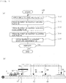
- Figs. 1 are drawings for explaining a printing method according to Embodiment 1 of the present invention, Fig. 1(a) being an operation flowchart and Fig. 1 (b) being a schematic side view showing the operation flow.
- the printing method 100 includes an application process (S1) in which ink 2 is applied to an original plate 10 so as to form a predetermined print pattern 1 (see Fig. 2 ), a transfer process (S2) in which a printing blanket (hereinafter, simply “blanket”) 20 is pressed against the original plate 10 to which the ink 2 has been applied in accordance with the print pattern 1, a printing process (S3) in which the blanket 20, to which the ink 2 has been transferred is pressed against a surface to be printed 30 (corresponding to the surface of the printing medium), to thereby transfer the ink 2 on the blanket 20 to the surface to be printed 30, a cleaning process (S4) in which the blanket 20, from which the ink 2 has been transferred to the surface to be printed 30, is pressed against a flat cleaning surface 40, to thereby transfer the residual ink 2 on the blanket 20 to the cleaning surface 40, and a surface activation process (S5) in which the blanket 20, from which the residual ink 2 has been transferred to the cleaning surface
- the blanket 20 having the part of the water or solvent adhering thereto or impregnated therein may be air-blown, to thereby remove the water or solvent adhering thereto or impregnated therein, or the blanket 20 may be pressed against a flat dry surface to thereby remove the water or solvent adhering thereto or impregnated therein.
- Fig. 2 to Fig. 6 are side views showing the progress of operation corresponding to each process of the printing method according to Embodiment 1 of the present invention, Fig. 2 showing the application process, Fig. 3 showing the transfer process, Fig. 4 showing the printing process, Fig. 5 showing the cleaning process, and Fig. 6 showing the surface activation process.
- the ink 2 is applied generally over the entire surface of the original plate 10 in a uniform thickness with a roller 3, and the ink 2 applied generally all over is partially removed so that the remaining portion of the ink 2 (indicated by hatched portions of exaggerated film thickness) forms a print pattern 1 (letterpress printing).
- a print pattern 1 letterpress printing
- water may be impregnated in the original plate 10 in accordance with the print pattern 1, so that the water repels a part of the ink 2.
- a masking material 10a is provided all over the original plate 10, and a recessed portion 10b corresponding to the print pattern 1 is formed in the masking material 10a in Fig. 2(c) , and the recessed portion 10b is filled with the ink 2 in Fig. 2(d) (intaglio printing).
- a silicone material may be applied to the original plate 10 in accordance with the print pattern 1, so that the silicone material repels a part of the ink 2.
- the method of applying the ink 2 to the original plate 10 so as to form a predetermined print pattern 1 is not specifically limited, and either of the letterpress printing and the intaglio printing may be employed.
- the blanket 20 is pressed against the original plate 10 (more precisely, the surface of the original plate 10) to which the ink 2 is adhering in accordance with the print pattern 1, to thereby transfer the ink 2 to the blanket 20.
- the process of pressing the blanket 20 (velocity of descending) against the original plate 10 will be subsequently described in details.
- the blanket 20 to which the ink 2 has been transferred is pressed against the surface to be printed 30, to thereby transfer the ink 2 on the blanket 20 to the surface to be printed 30.
- the surface to be printed 30 is illustrated as a flat surface in Figs. 4(a) and 4(b)
- the surface to be printed 30 may be a non-flat surface (curved surface) without limitation to the flat surface. The process of pressing the blanket 20 (velocity of descending) against the surface to be printed 30 will be subsequently described in details.
- the blanket 20 from which the ink 2 has been transferred to the surface to be printed 30 is pressed against the cleaning surface 40 which is flat, to thereby transfer the ink 2 remaining on the blanket 20 to the cleaning surface 40.
- the material of the cleaning surface 40 is not specifically limited, though it is preferable to employ paper or an adhesive tape.
- the blanket 20 which has undergone the cleaning process is pressed against the moisture absorbent 50, to thereby apply a part of water or solvent impregnated in the moisture absorbent 50 to the blanket 20, or impregnate the blanket 20 with the water or solvent.
- the moisture absorbent 50 may preferably be composed of approximately fifty stacked paper sheets impregnated with water or solvent, however a different material may be employed provided that the material has moisture absorption capability.
- the moisture absorbent 50 may be formed of a single sheet instead of a plurality of stacked sheets.
- the solvent may be selected according to the properties of the ink 2 from among the materials capable of softening the ink 2 which is hard, examples of which include, without limitation thereto, thinner, xylene, and toluene.
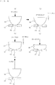
- Figs. 7 are side views for explaining the transfer process in the printing method according to Embodiment 1 of the present invention, Fig. 7(a) showing start of contact, Fig. 7(b) showing a state immediately after the start of contact, Fig. 7(c) showing a state in which the contact is in progress, Fig. 7(d) showing a state in which the contact is closest, and Fig. 7(e) showing separation.
- the blanket 20 is made to descend toward the original plate 10 at a predetermined velocity V, and the velocity of descending of the blanket 20 is reduced (for example, to 10 to 15% of the velocity V) when the blanket 20 starts to contact the original plate 10 (more precisely, immediately before the blanket 20 is brought into contact).
- the descent of the blanket 20 is temporarily stopped (for example, 0.5 to 1.0 second), when the blanket 20 is slightly brought into contact with the original plate 10 (for example, when the blanket 20 is pressed against the original plate 10 by approximately 0.5 to 1.0 mm).
- the blanket 20 is pressed further against the original plate 10 (for example, by a stroke of 10 to 20 mm) after the temporary stop, while gradually increasing the velocity of descending.
- the velocity of descending of the blanket 20 is sufficiently increased (for example, 50 to 60% of the velocity V).
- the blanket 20 is made to ascend thus to be separated from the original plate 10, as shown in Fig. 7(e) .
- the velocity of ascending of the blanket 20 is equal to the velocity V (100% of the velocity V).
- Fig. 8 is a side view for explaining the contact area between the blanket 20 and the original plate 10, with respect to the transfer process in the printing method according to Embodiment 1 of the present invention.
- the printing method 100 while the curvature radius of the blanket 20 (more precisely, the curvature radius of the cross-section approximately regarded as an arc) is sufficiently large at the moment of contact and immediately after the contact, the velocity of descending is made slower. Accordingly, the distance H per unit time in the equation cited above is reduced, and therefore the increment ⁇ S of the contact area per unit time is reduced.
- the mentioned method eliminates the need to make the printing blanket smaller, reduce the curvature radius of the end portion, increase the height, and employing a softer material, all of which lead to an increase in printing cost and degradation in printing efficiency. Therefore, a high-quality printed product can be obtained at a lower cost.
- the velocity of descending is increased. Accordingly, the distance H per unit time in the equation cited above is increased and therefore the increment ⁇ S of the contact area per unit time does not largely vary. Consequently, the ambient air can be prevented from being caught between the surface of the blanket 20 and the surface of the original plate, despite the velocity of descending being increased.
- the velocity of descending is increased when the contact is made over a larger area, the printing time is prevented from being prolonged compared with the case of reducing the velocity of descending throughout the contacting process. Therefore, degradation in printing efficiency and in productivity (mass production efficiency) can be suppressed.
- the level (extent of reduction) of the velocity of descending at the moment of the contact, the level (extent of increase) of the velocity of descending after the contact, and the timing and method (whether gradually or stepwise) of changing the velocity of descending are not specifically limited.
- the velocity of descending V for making the contact and the ascending velocity for separating the blanket 20 from the original plate 10 after the contact is finished may be different from each other.
- the descent of the blanket 20 is temporarily stopped when the contact is slightly made in Embodiment 1, the temporary stop may be skipped, without limitation to the above.
- the velocity of descending of the blanket 20 is reduced when the blanket 20 starts to contact the surface to be printed 30 as in the transfer process (S2), because ambient air may be caught as in the transfer process (S2). Then when the blanket 20 slightly contacts the surface to be printed 30, the descent of the blanket 20 is temporarily stopped. After the temporary stop, the blanket 20 is pressed further against the surface to be printed 30 while gradually increasing the velocity of descending.
- ambient air can be prevented from being caught between the surface of the blanket 20 and the surface of the surface to be printed 30 as in the transfer process (S2), and therefore degradation in printing efficiency and in productivity (mass production efficiency) can be suppressed.
- Figs. 9(a) to 9(e) are side views showing a printing process for explaining a printing method according to Embodiment 2 of the present invention, Fig. 9(a) showing the moment of contact, Fig. 9(b) showing the state immediately after the start of contact, Fig. 9(c) showing a state in which the contact is in progress, Fig. 9(d) showing a state in which the contact is closest, and Fig. 9(e) showing the separation.
- the same constituents as those of Embodiment 1 will be given the same numeral, and the description thereof will not be repeated.
- the printing method 200 according to the present invention will be described hereunder on the assumption that the surface to be printed is formed with a hole of a circular shape in a cross-sectional view.
- the present invention is not limited to such a configuration but the surface to be printed may include a bottomed hole, in other words a recessed portion, and the cross-sectional shape thereof may be other than circular.
- a circular hole 61 is formed in a surface to be printed 60, and the boundary between the surface to be printed 60 and the hole 61 will be referred to as hole periphery 62.
- the blanket 20 is made to descend toward the surface to be printed 60 at a predetermined velocity V, and the velocity of descending of the blanket 20 is reduced (for example, to 10 to 15% of the velocity V) when the blanket 20 starts to contact the surface to be printed 60 (more precisely, immediately before the blanket 20 is brought into contact).
- the descent of the blanket 20 is temporarily stopped (for example, 0.5 to 1.0 second), when the blanket 20 is slightly brought into contact with the hole periphery 62 of the surface to be printed 60 (for example, when the blanket 20 is pressed against the surface to be printed 60 by approximately 0.5 to 1.0 mm).
- the blanket 20 is pressed further against the surface to be printed 60 (for example, by a stroke of 10 to 20 mm) after the temporary stop, while gradually increasing the velocity of descending.
- the velocity of descending of the blanket 20 is sufficiently increased (for example, 50 to 60% of the velocity V).
- the blanket 20 is made to ascend thus to be separated from the surface to be printed 60, as shown in Fig. 9(e) .
- the velocity of ascending of the blanket 20 is equal to the velocity V (100% of the velocity V).
- the velocity of descending is made slower at the moment that the blanket 20 starts to contact the hole periphery 62 of the surface to be printed 60 and immediately after the contact, and therefore the increment ⁇ S of the contact area per unit time is reduced.
- a time for ambient air to escape from the wedge-shaped space defined between the surface of the blanket 20 and the surface to be printed 60 is secured at the moment of contact and immediately after the contact, and therefore the ambient air can be prevented from being caught between the surface of the blanket 20 and the surface to be printed 60. Therefore, a high-quality printed product can be obtained at a lower cost, as in Embodiment 1.
- Figs. 10 are side views showing a printing process for explaining a printing method according to Embodiment 3 of the present invention, Fig. 10(a) showing the state immediately after the start of contact, Figs. 10(b) and 10(c) showing a state in which the contact is in progress, Fig. 10(d) showing a state immediately before a closest contact, and Fig. 10(e) showing the separation.
- the same constituents as those of Embodiment 1 will be given the same numeral, and the description thereof will not be repeated.
- the printing method 300 according to the present invention will be described hereunder on the assumption that the surface to be printed includes an annular protruding portion having smooth outskirts.
- the present invention is not limited to such a configuration, but the surface to be printed may include discontinuous projections or a linear rib , the number and the layout of which (whether symmetric or asymmetric, in the case of plurality) may be determined as desired.
- the surface to be printed 70 includes a flat portion 71 and an annular protruding portion 73, which are connected via a corner portion 72 having an arcuate cross-sectional shape.
- the curvature radius of the cross-section of the corner portion 72 will be denoted by "Rp".
- the blanket 20 is made to descend toward the surface to be printed 70 at a predetermined velocity V, and the velocity of descending of the blanket 20 is reduced (for example, to 10% to 15% of the velocity V) when the blanket 20 starts to contact the flat portion 71 of the surface to be printed 70 (more precisely, immediately before the blanket 20 is brought into contact). Then the descent of the blanket 20 is temporarily stopped (for example, 0.5% to 1.0 second, though not shown) when the blanket 20 is slightly brought into contact with the flat portion 71 of the surface to be printed 70 (for example, when the blanket 20 is pressed against the surface to be printed 70 by approximately 0.5% to 1.0 mm).
- the blanket 20 is pressed further against the flat portion 71 of the surface to be printed 70 (for example, by a stroke of 10 to 20 mm) after the temporary stop, while gradually increasing the velocity of descending.
- the velocity of descending of the blanket 20 is sufficiently increased (for example, 50 to 60% of the velocity V), until immediately before the blanket 20 reaches the corner portion 72 of the surface to be printed 70.
- the velocity of descending of the blanket 20 is reduced, and when the lateral face of the blanket 20 is abutted against the corner portion 72 the velocity of descending of the blanket 20 is reduced to a level similar to the velocity at the start of the contact (for example, 5 to 10% of the velocity V). Thereafter, the lateral face of the blanket 20 is pressed against the protruding portion 73 of the surface to be printed 70, at the same reduced velocity (not shown).
- a curvature radius Rb representing the curvature radius of the cross-section of the portion of the blanket 20 pressed against the corner portion 72, is larger than a half of the curvature radius Rp of the cross-section of the corner portion 72, but smaller than the curvature radius Rp (Rp/2 ⁇ Rb ⁇ Rp).
- the blanket 20 is made to ascend thus to be separated from the surface to be printed 70, as shown in Fig. 10(e) .
- the velocity of ascending of the blanket 20 is equal to the velocity V (100% of the velocity V).
- the velocity of descending is made slower at the moment that the blanket 20 starts to contact the flat portion 71 of the surface to be printed 70 and immediately after the contact, but then made faster until the blanket 20 comes close to the corner portion 72, at which point the velocity of descending is again reduced, and when the blanket 20 is pressed against the corner portion 72 the velocity of descending is reduced to a lowest level.
- the increment ⁇ S (not shown) of the contact area per unit time is reduced, and therefore a time for ambient air to escape from the wedge-shaped space defined between the surface of the blanket 20 and the surface to be printed 70 (flat portion 71, corner portion 72, and protruding portion 73) is secured.
- the ambient air can be prevented from being caught between the surface of the blanket 20 and the surface to be printed 70. Therefore, a high-quality printed product can be obtained at a lower cost, as in Embodiment 1.
- the present invention prevents ambient air from being caught between the surface of the blanket and the surface of the original plate, as well as between the surface of the blanket and the surface of the printing medium, and is therefore broadly applicable to printing processes that employ various types (shape, size, material, and so forth) of blankets.
Landscapes
- Engineering & Computer Science (AREA)
- Mechanical Engineering (AREA)
- Printing Methods (AREA)
- Inking, Control Or Cleaning Of Printing Machines (AREA)
Applications Claiming Priority (3)
| Application Number | Priority Date | Filing Date | Title |
|---|---|---|---|
| JP2013108620A JP2014226859A (ja) | 2013-05-23 | 2013-05-23 | 印刷方法 |
| PCT/JP2013/076573 WO2014188611A1 (ja) | 2013-05-23 | 2013-09-30 | 印刷方法 |
| PCT/JP2014/063710 WO2014189131A1 (ja) | 2013-05-23 | 2014-05-23 | 印刷方法 |
Publications (3)
| Publication Number | Publication Date |
|---|---|
| EP3000606A1 EP3000606A1 (en) | 2016-03-30 |
| EP3000606A4 EP3000606A4 (en) | 2017-04-05 |
| EP3000606B1 true EP3000606B1 (en) | 2020-04-22 |
Family
ID=51933191
Family Applications (1)
| Application Number | Title | Priority Date | Filing Date |
|---|---|---|---|
| EP14800613.3A Active EP3000606B1 (en) | 2013-05-23 | 2014-05-23 | Printing method |
Country Status (7)
| Country | Link |
|---|---|
| US (1) | US9321255B2 (ja) |
| EP (1) | EP3000606B1 (ja) |
| JP (2) | JP2014226859A (ja) |
| KR (1) | KR101694600B1 (ja) |
| CN (1) | CN104540683B (ja) |
| TW (1) | TWI558577B (ja) |
| WO (2) | WO2014188611A1 (ja) |
Families Citing this family (4)
| Publication number | Priority date | Publication date | Assignee | Title |
|---|---|---|---|---|
| US10800197B2 (en) | 2016-05-17 | 2020-10-13 | Shuhou Co., Ltd. | Printing blanket |
| KR102100669B1 (ko) | 2016-09-27 | 2020-05-27 | (주)엘지하우시스 | 차량용 내장재의 제조방법 및 차량용 내장재 |
| WO2018078694A1 (ja) * | 2016-10-24 | 2018-05-03 | 株式会社秀峰 | 印刷用ブランケットの活性化装置及び印刷用ブランケットを使用した印刷方法 |
| US12459247B2 (en) | 2022-04-28 | 2025-11-04 | Shuhou Co., Ltd. | Printing apparatus and method for producing printed item |
Family Cites Families (15)
| Publication number | Priority date | Publication date | Assignee | Title |
|---|---|---|---|---|
| JPS5363111A (en) * | 1976-11-15 | 1978-06-06 | Hamasawa Kogyo Kk | Automatic printer |
| DE3500291A1 (de) * | 1985-01-07 | 1986-07-10 | TAMPOflex GmbH, 7257 Ditzingen | Tamponschnelldruckmaschine |
| JPS63128941A (ja) * | 1986-11-19 | 1988-06-01 | Taihei Kogyo Kk | パツド印刷機における転写パツド駆動装置 |
| US4779531A (en) * | 1987-01-29 | 1988-10-25 | Teihi Kogyo Kabushiki Kaisha | Hand operated pad printing machine |
| US5272973A (en) * | 1993-01-22 | 1993-12-28 | United Silicone Inc. | Inkcup assembly and drive mechanism for pad printing machine |
| JP3127399B2 (ja) * | 1998-03-19 | 2001-01-22 | 日本写真印刷株式会社 | 屋内用化粧材とその製造方法 |
| JP2005212109A (ja) * | 2004-01-27 | 2005-08-11 | Fuji Photo Film Co Ltd | パッド支持体駆動装置およびこれを備えたサーボモータ駆動型パッド印刷機。 |
| DE602004014002D1 (de) * | 2004-12-10 | 2008-07-03 | Essilor Int | Stempel zum Auftragen eines Motivs, Verfahren zur Stempelherstellung und Verfahren zur Herstellung eines Objekts anhand von diesem Stempel |
| JP2008114496A (ja) | 2006-11-06 | 2008-05-22 | Fujifilm Corp | インキ密閉型パッド印刷機 |
| US8151704B2 (en) * | 2008-02-21 | 2012-04-10 | Bridgestone Sports Co., Ltd | Method for printing on spherical object and pad to be used therefor |
| US20100116159A1 (en) * | 2008-11-13 | 2010-05-13 | Larry Hines | Offset Printing Unit with Plate Cylinder Drive |
| FR2948061B1 (fr) * | 2009-07-15 | 2011-09-02 | Goss Int Montataire Sa | Procede de reglage de la vitesse angulaire de cylindres d'impression |
| DE102010012280A1 (de) * | 2010-03-22 | 2011-09-22 | Heidelberger Druckmaschinen Ag | Verfahren zum Wechseln von Druckplatten in Rotationsdruckmaschinen mit mehreren Druckwerken |
| KR101263253B1 (ko) * | 2010-11-24 | 2013-05-10 | 삼성전자주식회사 | 롤 프린팅 장치 |
| JP5766465B2 (ja) * | 2011-02-28 | 2015-08-19 | 順 阪本 | 印刷機、印刷装置および印刷方法 |
-
2013
- 2013-05-23 JP JP2013108620A patent/JP2014226859A/ja active Pending
- 2013-09-30 WO PCT/JP2013/076573 patent/WO2014188611A1/ja not_active Ceased
-
2014
- 2014-05-23 US US14/413,047 patent/US9321255B2/en active Active
- 2014-05-23 WO PCT/JP2014/063710 patent/WO2014189131A1/ja not_active Ceased
- 2014-05-23 CN CN201480001625.8A patent/CN104540683B/zh active Active
- 2014-05-23 TW TW103118029A patent/TWI558577B/zh active
- 2014-05-23 EP EP14800613.3A patent/EP3000606B1/en active Active
- 2014-05-23 JP JP2014560581A patent/JP5916903B2/ja active Active
- 2014-05-23 KR KR1020147035619A patent/KR101694600B1/ko active Active
Non-Patent Citations (1)
| Title |
|---|
| None * |
Also Published As
| Publication number | Publication date |
|---|---|
| EP3000606A1 (en) | 2016-03-30 |
| JP5916903B2 (ja) | 2016-05-11 |
| JP2014226859A (ja) | 2014-12-08 |
| TW201511975A (zh) | 2015-04-01 |
| US9321255B2 (en) | 2016-04-26 |
| WO2014189131A1 (ja) | 2014-11-27 |
| KR101694600B1 (ko) | 2017-01-17 |
| CN104540683B (zh) | 2017-03-08 |
| CN104540683A (zh) | 2015-04-22 |
| US20150165754A1 (en) | 2015-06-18 |
| WO2014188611A1 (ja) | 2014-11-27 |
| EP3000606A4 (en) | 2017-04-05 |
| TWI558577B (zh) | 2016-11-21 |
| KR20150011839A (ko) | 2015-02-02 |
| JPWO2014189131A1 (ja) | 2017-02-23 |
Similar Documents
| Publication | Publication Date | Title |
|---|---|---|
| EP3000606B1 (en) | Printing method | |
| JP5860012B2 (ja) | リチウムイオン二次電池の製造方法 | |
| US10800197B2 (en) | Printing blanket | |
| RU2673425C2 (ru) | Способ трафаретной печати | |
| JP7325599B2 (ja) | 印刷装置、及び印刷物の製造方法 | |
| US9475331B2 (en) | Plate printing method with blanket cleaning | |
| JP6529607B2 (ja) | 印刷用ブランケットの製造方法 | |
| JP5981276B2 (ja) | スクリーン印刷機およびスクリーン印刷方法 | |
| JP5924564B2 (ja) | 塗布容器用のローラの製造方法 | |
| US11325411B2 (en) | Printing blanket and method for manufacturing printing blanket | |
| JP2015089670A (ja) | 印刷方法 | |
| CN207267381U (zh) | 印刷胶辊 | |
| TWI850468B (zh) | 三種介電質之電流體動力圖案化 | |
| JP5799945B2 (ja) | スタンプ及び版 | |
| JP2005262152A (ja) | ロールコータ装置 | |
| KR20230073639A (ko) | 속도 성능이 향상된 그라비아 인쇄 장치 | |
| KR20160092325A (ko) | 그라비어 롤러 및 이를 포함하는 그라비어 인쇄장치 | |
| JP2016150494A (ja) | パッドおよびパッド印刷装置 | |
| TH66819B (th) | วิธีการพิมพ์ | |
| JP2002211093A (ja) | インキ含浸器 | |
| JP2019115495A (ja) | 化粧品の製造方法 | |
| JPH10323966A (ja) | パットプレス印刷に用いるパット装置および当装置を利用する方法 | |
| JP2006198477A (ja) | ブレード塗布方法及びこれを用いたディスク塗布方法並びにブレード塗布装置 | |
| JP2016165861A (ja) | 印刷物の製造方法および印刷装置 | |
| JP2012252942A (ja) | 電線のマーキング装置及び方法 |
Legal Events
| Date | Code | Title | Description |
|---|---|---|---|
| PUAI | Public reference made under article 153(3) epc to a published international application that has entered the european phase |
Free format text: ORIGINAL CODE: 0009012 |
|
| 17P | Request for examination filed |
Effective date: 20141230 |
|
| AK | Designated contracting states |
Kind code of ref document: A1 Designated state(s): AL AT BE BG CH CY CZ DE DK EE ES FI FR GB GR HR HU IE IS IT LI LT LU LV MC MK MT NL NO PL PT RO RS SE SI SK SM TR |
|
| AX | Request for extension of the european patent |
Extension state: BA ME |
|
| DAX | Request for extension of the european patent (deleted) | ||
| A4 | Supplementary search report drawn up and despatched |
Effective date: 20170302 |
|
| RIC1 | Information provided on ipc code assigned before grant |
Ipc: B41M 1/02 20060101ALN20170224BHEP Ipc: B41M 1/10 20060101ALN20170224BHEP Ipc: B41M 1/40 20060101ALN20170224BHEP Ipc: B41F 17/00 20060101AFI20170224BHEP |
|
| REG | Reference to a national code |
Ref country code: DE Ref legal event code: R079 Ref document number: 602014064201 Country of ref document: DE Free format text: PREVIOUS MAIN CLASS: B41M0001400000 Ipc: B41F0017000000 |
|
| GRAP | Despatch of communication of intention to grant a patent |
Free format text: ORIGINAL CODE: EPIDOSNIGR1 |
|
| STAA | Information on the status of an ep patent application or granted ep patent |
Free format text: STATUS: GRANT OF PATENT IS INTENDED |
|
| RIC1 | Information provided on ipc code assigned before grant |
Ipc: B41M 1/02 20060101ALN20191209BHEP Ipc: B41F 17/00 20060101AFI20191209BHEP Ipc: B41M 1/10 20060101ALN20191209BHEP Ipc: B41M 1/40 20060101ALN20191209BHEP |
|
| INTG | Intention to grant announced |
Effective date: 20200110 |
|
| GRAS | Grant fee paid |
Free format text: ORIGINAL CODE: EPIDOSNIGR3 |
|
| GRAA | (expected) grant |
Free format text: ORIGINAL CODE: 0009210 |
|
| STAA | Information on the status of an ep patent application or granted ep patent |
Free format text: STATUS: THE PATENT HAS BEEN GRANTED |
|
| AK | Designated contracting states |
Kind code of ref document: B1 Designated state(s): AL AT BE BG CH CY CZ DE DK EE ES FI FR GB GR HR HU IE IS IT LI LT LU LV MC MK MT NL NO PL PT RO RS SE SI SK SM TR |
|
| REG | Reference to a national code |
Ref country code: CH Ref legal event code: EP |
|
| REG | Reference to a national code |
Ref country code: DE Ref legal event code: R096 Ref document number: 602014064201 Country of ref document: DE |
|
| REG | Reference to a national code |
Ref country code: IE Ref legal event code: FG4D |
|
| REG | Reference to a national code |
Ref country code: AT Ref legal event code: REF Ref document number: 1259578 Country of ref document: AT Kind code of ref document: T Effective date: 20200515 |
|
| REG | Reference to a national code |
Ref country code: LT Ref legal event code: MG4D |
|
| REG | Reference to a national code |
Ref country code: NL Ref legal event code: MP Effective date: 20200422 |
|
| PG25 | Lapsed in a contracting state [announced via postgrant information from national office to epo] |
Ref country code: IS Free format text: LAPSE BECAUSE OF FAILURE TO SUBMIT A TRANSLATION OF THE DESCRIPTION OR TO PAY THE FEE WITHIN THE PRESCRIBED TIME-LIMIT Effective date: 20200822 Ref country code: FI Free format text: LAPSE BECAUSE OF FAILURE TO SUBMIT A TRANSLATION OF THE DESCRIPTION OR TO PAY THE FEE WITHIN THE PRESCRIBED TIME-LIMIT Effective date: 20200422 Ref country code: LT Free format text: LAPSE BECAUSE OF FAILURE TO SUBMIT A TRANSLATION OF THE DESCRIPTION OR TO PAY THE FEE WITHIN THE PRESCRIBED TIME-LIMIT Effective date: 20200422 Ref country code: NO Free format text: LAPSE BECAUSE OF FAILURE TO SUBMIT A TRANSLATION OF THE DESCRIPTION OR TO PAY THE FEE WITHIN THE PRESCRIBED TIME-LIMIT Effective date: 20200722 Ref country code: GR Free format text: LAPSE BECAUSE OF FAILURE TO SUBMIT A TRANSLATION OF THE DESCRIPTION OR TO PAY THE FEE WITHIN THE PRESCRIBED TIME-LIMIT Effective date: 20200723 Ref country code: SE Free format text: LAPSE BECAUSE OF FAILURE TO SUBMIT A TRANSLATION OF THE DESCRIPTION OR TO PAY THE FEE WITHIN THE PRESCRIBED TIME-LIMIT Effective date: 20200422 Ref country code: NL Free format text: LAPSE BECAUSE OF FAILURE TO SUBMIT A TRANSLATION OF THE DESCRIPTION OR TO PAY THE FEE WITHIN THE PRESCRIBED TIME-LIMIT Effective date: 20200422 Ref country code: PT Free format text: LAPSE BECAUSE OF FAILURE TO SUBMIT A TRANSLATION OF THE DESCRIPTION OR TO PAY THE FEE WITHIN THE PRESCRIBED TIME-LIMIT Effective date: 20200824 |
|
| REG | Reference to a national code |
Ref country code: AT Ref legal event code: MK05 Ref document number: 1259578 Country of ref document: AT Kind code of ref document: T Effective date: 20200422 |
|
| PG25 | Lapsed in a contracting state [announced via postgrant information from national office to epo] |
Ref country code: BG Free format text: LAPSE BECAUSE OF FAILURE TO SUBMIT A TRANSLATION OF THE DESCRIPTION OR TO PAY THE FEE WITHIN THE PRESCRIBED TIME-LIMIT Effective date: 20200722 Ref country code: HR Free format text: LAPSE BECAUSE OF FAILURE TO SUBMIT A TRANSLATION OF THE DESCRIPTION OR TO PAY THE FEE WITHIN THE PRESCRIBED TIME-LIMIT Effective date: 20200422 Ref country code: LV Free format text: LAPSE BECAUSE OF FAILURE TO SUBMIT A TRANSLATION OF THE DESCRIPTION OR TO PAY THE FEE WITHIN THE PRESCRIBED TIME-LIMIT Effective date: 20200422 Ref country code: RS Free format text: LAPSE BECAUSE OF FAILURE TO SUBMIT A TRANSLATION OF THE DESCRIPTION OR TO PAY THE FEE WITHIN THE PRESCRIBED TIME-LIMIT Effective date: 20200422 |
|
| PG25 | Lapsed in a contracting state [announced via postgrant information from national office to epo] |
Ref country code: AL Free format text: LAPSE BECAUSE OF FAILURE TO SUBMIT A TRANSLATION OF THE DESCRIPTION OR TO PAY THE FEE WITHIN THE PRESCRIBED TIME-LIMIT Effective date: 20200422 |
|
| REG | Reference to a national code |
Ref country code: DE Ref legal event code: R097 Ref document number: 602014064201 Country of ref document: DE |
|
| PG25 | Lapsed in a contracting state [announced via postgrant information from national office to epo] |
Ref country code: DK Free format text: LAPSE BECAUSE OF FAILURE TO SUBMIT A TRANSLATION OF THE DESCRIPTION OR TO PAY THE FEE WITHIN THE PRESCRIBED TIME-LIMIT Effective date: 20200422 Ref country code: LI Free format text: LAPSE BECAUSE OF NON-PAYMENT OF DUE FEES Effective date: 20200531 Ref country code: ES Free format text: LAPSE BECAUSE OF FAILURE TO SUBMIT A TRANSLATION OF THE DESCRIPTION OR TO PAY THE FEE WITHIN THE PRESCRIBED TIME-LIMIT Effective date: 20200422 Ref country code: MC Free format text: LAPSE BECAUSE OF FAILURE TO SUBMIT A TRANSLATION OF THE DESCRIPTION OR TO PAY THE FEE WITHIN THE PRESCRIBED TIME-LIMIT Effective date: 20200422 Ref country code: IT Free format text: LAPSE BECAUSE OF FAILURE TO SUBMIT A TRANSLATION OF THE DESCRIPTION OR TO PAY THE FEE WITHIN THE PRESCRIBED TIME-LIMIT Effective date: 20200422 Ref country code: RO Free format text: LAPSE BECAUSE OF FAILURE TO SUBMIT A TRANSLATION OF THE DESCRIPTION OR TO PAY THE FEE WITHIN THE PRESCRIBED TIME-LIMIT Effective date: 20200422 Ref country code: CZ Free format text: LAPSE BECAUSE OF FAILURE TO SUBMIT A TRANSLATION OF THE DESCRIPTION OR TO PAY THE FEE WITHIN THE PRESCRIBED TIME-LIMIT Effective date: 20200422 Ref country code: CH Free format text: LAPSE BECAUSE OF NON-PAYMENT OF DUE FEES Effective date: 20200531 Ref country code: SM Free format text: LAPSE BECAUSE OF FAILURE TO SUBMIT A TRANSLATION OF THE DESCRIPTION OR TO PAY THE FEE WITHIN THE PRESCRIBED TIME-LIMIT Effective date: 20200422 Ref country code: EE Free format text: LAPSE BECAUSE OF FAILURE TO SUBMIT A TRANSLATION OF THE DESCRIPTION OR TO PAY THE FEE WITHIN THE PRESCRIBED TIME-LIMIT Effective date: 20200422 Ref country code: AT Free format text: LAPSE BECAUSE OF FAILURE TO SUBMIT A TRANSLATION OF THE DESCRIPTION OR TO PAY THE FEE WITHIN THE PRESCRIBED TIME-LIMIT Effective date: 20200422 |
|
| PG25 | Lapsed in a contracting state [announced via postgrant information from national office to epo] |
Ref country code: PL Free format text: LAPSE BECAUSE OF FAILURE TO SUBMIT A TRANSLATION OF THE DESCRIPTION OR TO PAY THE FEE WITHIN THE PRESCRIBED TIME-LIMIT Effective date: 20200422 Ref country code: SK Free format text: LAPSE BECAUSE OF FAILURE TO SUBMIT A TRANSLATION OF THE DESCRIPTION OR TO PAY THE FEE WITHIN THE PRESCRIBED TIME-LIMIT Effective date: 20200422 |
|
| PLBE | No opposition filed within time limit |
Free format text: ORIGINAL CODE: 0009261 |
|
| STAA | Information on the status of an ep patent application or granted ep patent |
Free format text: STATUS: NO OPPOSITION FILED WITHIN TIME LIMIT |
|
| REG | Reference to a national code |
Ref country code: BE Ref legal event code: MM Effective date: 20200531 |
|
| 26N | No opposition filed |
Effective date: 20210125 |
|
| PG25 | Lapsed in a contracting state [announced via postgrant information from national office to epo] |
Ref country code: LU Free format text: LAPSE BECAUSE OF NON-PAYMENT OF DUE FEES Effective date: 20200523 |
|
| PG25 | Lapsed in a contracting state [announced via postgrant information from national office to epo] |
Ref country code: IE Free format text: LAPSE BECAUSE OF NON-PAYMENT OF DUE FEES Effective date: 20200523 |
|
| PG25 | Lapsed in a contracting state [announced via postgrant information from national office to epo] |
Ref country code: BE Free format text: LAPSE BECAUSE OF NON-PAYMENT OF DUE FEES Effective date: 20200531 Ref country code: SI Free format text: LAPSE BECAUSE OF FAILURE TO SUBMIT A TRANSLATION OF THE DESCRIPTION OR TO PAY THE FEE WITHIN THE PRESCRIBED TIME-LIMIT Effective date: 20200422 |
|
| PG25 | Lapsed in a contracting state [announced via postgrant information from national office to epo] |
Ref country code: TR Free format text: LAPSE BECAUSE OF FAILURE TO SUBMIT A TRANSLATION OF THE DESCRIPTION OR TO PAY THE FEE WITHIN THE PRESCRIBED TIME-LIMIT Effective date: 20200422 Ref country code: MT Free format text: LAPSE BECAUSE OF FAILURE TO SUBMIT A TRANSLATION OF THE DESCRIPTION OR TO PAY THE FEE WITHIN THE PRESCRIBED TIME-LIMIT Effective date: 20200422 Ref country code: CY Free format text: LAPSE BECAUSE OF FAILURE TO SUBMIT A TRANSLATION OF THE DESCRIPTION OR TO PAY THE FEE WITHIN THE PRESCRIBED TIME-LIMIT Effective date: 20200422 |
|
| PG25 | Lapsed in a contracting state [announced via postgrant information from national office to epo] |
Ref country code: MK Free format text: LAPSE BECAUSE OF FAILURE TO SUBMIT A TRANSLATION OF THE DESCRIPTION OR TO PAY THE FEE WITHIN THE PRESCRIBED TIME-LIMIT Effective date: 20200422 |
|
| REG | Reference to a national code |
Ref country code: FR Ref legal event code: PLFP Year of fee payment: 10 |
|
| P01 | Opt-out of the competence of the unified patent court (upc) registered |
Effective date: 20230417 |
|
| PGFP | Annual fee paid to national office [announced via postgrant information from national office to epo] |
Ref country code: DE Payment date: 20250402 Year of fee payment: 12 |
|
| PGFP | Annual fee paid to national office [announced via postgrant information from national office to epo] |
Ref country code: FR Payment date: 20250401 Year of fee payment: 12 |
|
| PGFP | Annual fee paid to national office [announced via postgrant information from national office to epo] |
Ref country code: GB Payment date: 20260323 Year of fee payment: 13 |