EP3012123A1 - Fahrzeugluftreifen - Google Patents
Fahrzeugluftreifen Download PDFInfo
- Publication number
- EP3012123A1 EP3012123A1 EP15179617.4A EP15179617A EP3012123A1 EP 3012123 A1 EP3012123 A1 EP 3012123A1 EP 15179617 A EP15179617 A EP 15179617A EP 3012123 A1 EP3012123 A1 EP 3012123A1
- Authority
- EP
- European Patent Office
- Prior art keywords
- bead
- shore
- carcass
- hardness
- axially
- Prior art date
- Legal status (The legal status is an assumption and is not a legal conclusion. Google has not performed a legal analysis and makes no representation as to the accuracy of the status listed.)
- Granted
Links
Images



Classifications
-
- B—PERFORMING OPERATIONS; TRANSPORTING
- B60—VEHICLES IN GENERAL
- B60C—VEHICLE TYRES; TYRE INFLATION; TYRE CHANGING; CONNECTING VALVES TO INFLATABLE ELASTIC BODIES IN GENERAL; DEVICES OR ARRANGEMENTS RELATED TO TYRES
- B60C15/00—Tyre beads, e.g. ply turn-up or overlap
- B60C15/0009—Tyre beads, e.g. ply turn-up or overlap features of the carcass terminal portion
- B60C15/0036—Tyre beads, e.g. ply turn-up or overlap features of the carcass terminal portion with high ply turn-up, i.e. folded around the bead core and terminating radially above the point of maximum section width
-
- B—PERFORMING OPERATIONS; TRANSPORTING
- B60—VEHICLES IN GENERAL
- B60C—VEHICLE TYRES; TYRE INFLATION; TYRE CHANGING; CONNECTING VALVES TO INFLATABLE ELASTIC BODIES IN GENERAL; DEVICES OR ARRANGEMENTS RELATED TO TYRES
- B60C15/00—Tyre beads, e.g. ply turn-up or overlap
- B60C15/0009—Tyre beads, e.g. ply turn-up or overlap features of the carcass terminal portion
- B60C15/0036—Tyre beads, e.g. ply turn-up or overlap features of the carcass terminal portion with high ply turn-up, i.e. folded around the bead core and terminating radially above the point of maximum section width
- B60C15/0045—Tyre beads, e.g. ply turn-up or overlap features of the carcass terminal portion with high ply turn-up, i.e. folded around the bead core and terminating radially above the point of maximum section width with ply turn-up up to the belt edges, i.e. folded around the bead core and extending to the belt edges
-
- B—PERFORMING OPERATIONS; TRANSPORTING
- B60—VEHICLES IN GENERAL
- B60C—VEHICLE TYRES; TYRE INFLATION; TYRE CHANGING; CONNECTING VALVES TO INFLATABLE ELASTIC BODIES IN GENERAL; DEVICES OR ARRANGEMENTS RELATED TO TYRES
- B60C15/00—Tyre beads, e.g. ply turn-up or overlap
- B60C15/06—Flipper strips, fillers, or chafing strips and reinforcing layers for the construction of the bead
- B60C15/0603—Flipper strips, fillers, or chafing strips and reinforcing layers for the construction of the bead characterised by features of the bead filler or apex
-
- B—PERFORMING OPERATIONS; TRANSPORTING
- B60—VEHICLES IN GENERAL
- B60C—VEHICLE TYRES; TYRE INFLATION; TYRE CHANGING; CONNECTING VALVES TO INFLATABLE ELASTIC BODIES IN GENERAL; DEVICES OR ARRANGEMENTS RELATED TO TYRES
- B60C15/00—Tyre beads, e.g. ply turn-up or overlap
- B60C15/0009—Tyre beads, e.g. ply turn-up or overlap features of the carcass terminal portion
- B60C15/0018—Tyre beads, e.g. ply turn-up or overlap features of the carcass terminal portion not folded around the bead core, e.g. floating or down ply
-
- B—PERFORMING OPERATIONS; TRANSPORTING
- B60—VEHICLES IN GENERAL
- B60C—VEHICLE TYRES; TYRE INFLATION; TYRE CHANGING; CONNECTING VALVES TO INFLATABLE ELASTIC BODIES IN GENERAL; DEVICES OR ARRANGEMENTS RELATED TO TYRES
- B60C15/00—Tyre beads, e.g. ply turn-up or overlap
- B60C15/06—Flipper strips, fillers, or chafing strips and reinforcing layers for the construction of the bead
- B60C2015/0614—Flipper strips, fillers, or chafing strips and reinforcing layers for the construction of the bead characterised by features of the chafer or clinch portion, i.e. the part of the bead contacting the rim
-
- B—PERFORMING OPERATIONS; TRANSPORTING
- B60—VEHICLES IN GENERAL
- B60C—VEHICLE TYRES; TYRE INFLATION; TYRE CHANGING; CONNECTING VALVES TO INFLATABLE ELASTIC BODIES IN GENERAL; DEVICES OR ARRANGEMENTS RELATED TO TYRES
- B60C15/00—Tyre beads, e.g. ply turn-up or overlap
- B60C15/06—Flipper strips, fillers, or chafing strips and reinforcing layers for the construction of the bead
- B60C2015/0617—Flipper strips, fillers, or chafing strips and reinforcing layers for the construction of the bead comprising a cushion rubber other than the chafer or clinch rubber
- B60C2015/0621—Flipper strips, fillers, or chafing strips and reinforcing layers for the construction of the bead comprising a cushion rubber other than the chafer or clinch rubber adjacent to the carcass turnup portion
-
- B—PERFORMING OPERATIONS; TRANSPORTING
- B60—VEHICLES IN GENERAL
- B60C—VEHICLE TYRES; TYRE INFLATION; TYRE CHANGING; CONNECTING VALVES TO INFLATABLE ELASTIC BODIES IN GENERAL; DEVICES OR ARRANGEMENTS RELATED TO TYRES
- B60C15/00—Tyre beads, e.g. ply turn-up or overlap
- B60C15/06—Flipper strips, fillers, or chafing strips and reinforcing layers for the construction of the bead
- B60C15/0628—Flipper strips, fillers, or chafing strips and reinforcing layers for the construction of the bead comprising a bead reinforcing layer
- B60C2015/065—Flipper strips, fillers, or chafing strips and reinforcing layers for the construction of the bead comprising a bead reinforcing layer at the axially outer side of the carcass turn-up portion not wrapped around the bead core
-
- B—PERFORMING OPERATIONS; TRANSPORTING
- B60—VEHICLES IN GENERAL
- B60C—VEHICLE TYRES; TYRE INFLATION; TYRE CHANGING; CONNECTING VALVES TO INFLATABLE ELASTIC BODIES IN GENERAL; DEVICES OR ARRANGEMENTS RELATED TO TYRES
- B60C2200/00—Tyres specially adapted for particular applications
- B60C2200/04—Tyres specially adapted for particular applications for road vehicles, e.g. passenger cars
Definitions
- the invention relates to a pneumatic vehicle tire for a car, van or light truck with a radial carcass and with two bead areas, each having at least one bead core, a bead core rider seated on the bead core and a bead strip axially outwardly bounding the bead area, the radial carcass extending axially inward axially outwardly around the bead cores and terminating in a carcass turnup, and wherein the beaded portion members, radial carcass and bead strips disposed in the bead portion have certain Shore A hardnesses.
- Rubber compounds of tire components have certain Shore A hardnesses. Higher Shore A hardness describes harder rubber compounds, while lower Shore A hardness describes softer rubber compounds.
- the object is achieved by the Shore A hardness of axially immediately adjacent arranged in the bead area components not more than 5 Shore A hardness points from each other.
- the Shore A hardness of a component it is always meant the Shore A hardness of the rubber composition of that component.
- the component may consist entirely of one or more rubber compound or the component may be a rubberized strength carrier having position.
- a vehicle tire for cars, vans or light trucks which has an improved durability even under so-called overload conditions. It is essential that this improved durability is not achieved by the use of additional reinforcing layers in the bead area.
- only the rubber mixtures of the components already used in the bead in the prior art are optimized with respect to their Shore A hardnesses.
- two axially juxtaposed components in the bead area have Shore A hardnesses that do not deviate from each other by more than 5 Shore A hardness points.
- the invention is therefore applicable without design adjustments to today already used tires.
- the inventors suspect that the advantageous effect according to the invention is due to a reduction of Rigidity jumps in the bead area is conditional.
- the Shore A hardness is determined according to DIN ISO 7619.
- “Axially adjacent components” means components which - viewed in the axial direction of the vehicle tire - are arranged side by side.
- Bead reinforcer means a gummed strength member having a position which is located in the bead area axially outward with respect to the carcass turn-up and does not rotate around the bead core.
- Pad strip means a layer made entirely of rubber, which is arranged in the bead area axially outward with respect to the carcass turn-up and does not circulate the bead core.
- the Shore A hardnesses are increasing from axially adjacent components disposed in the bead region, starting from the bead apex to the outside of the sidewall. This means that immediately adjacent components can have the same or within 5 points increasing Shore A hardnesses. Importantly, the Shore A hardness increases from the bead apex to the outside of the sidewall, in the sense that the bead apex has a lower Shore A hardness than the bead strip disposed axially outward of the bead apex.
- the Shore A hardnesses of components arranged axially adjacent in the bead region, starting from the bead apex to the outside of the side wall are preferred in that the bead apex has a hardness of 80 Shore A. and the bead strip has a hardness of 75 Shore A, or preferably that the bead apex has a hardness of 70 Shore A and the bead strip has a hardness of 60 Shore A. This means that immediately adjacent components can have the same or within five points falling Shore A hardnesses.
- the radial carcass is designed in one or two layers, wherein in the two-layered embodiment, preferably both layers have the same Shore A hardness.
- the single-ply radial carcass has a conventional construction ending in a carcass turn-up, the end of the carcass puff preferably being at the level of the sidewall above the top of the bead apex and below and away from the belt, or preferably having a so-called "C-ply construction".
- the end of the carcass rash the entire tire sidewall is led up and extends below the belt edges.
- the two-ply radial carcass has a single-ply radial carcass construction in which the carcass puff is wrapped around the cores from inside to outside and the carcass pothole end is above the top of the bead apex at the side wall and a second carcass ply is radially outboard
- the first carcass ply is applied, but covers the carcass turn-up of the first carcass ply and does not wrap around the bead cores, but ends at the level of the bead core.
- one or two cushion strips are arranged between the bead reinforcement and the carcass. Between the radial carcass and the bead enhancer alone one or two pad strips and no other components are arranged.
- the following table shows five variants of the bead region of a passenger car, van or light truck tire according to the invention.
- the components are listed from left to right according to their arrangement in the right bead area of the tire section of Apex towards the outside of the tire.
- the cross indicates that this component is present / realized, the number next to the cross indicates the Shore A hardness of the relevant component. "-" indicates that the component in question is not present / realized.
- the Fig. 1 shows a half cross-section of a pneumatic vehicle tire according to the invention, here a pneumatic tire of radial type.
- the tire has a common standard construction, with two side walls 1, a crown region 2, with a carcass of a carcass ply 3, which surrounds the bead cores 4 and the bead apex 5 seated on the bead cores 4 from axially inside to axially outside and ends in a carcass turnup 3a , with an airtight running inner layer 6, a two-ply belt 7, which is covered by a belt bandage 8 and a tread 9.
- the end of the carcass loft 10 is above the bead apex 5 at the level of the side wall first
- the bead area 11 consists of the bead apex 5 axially outwardly of the following components: bead apex 5, carcass turn-up 3a, bead reinforcement 12 and bead strip 13.
- the bead reinforcement 12 has textile reinforcement and begins with its lower end at the level of the bead core and extends with his upper end to the upper third of the bead apex 5.
- the Shore A hardnesses of the components 5, 3a, 12, 13 arranged axially adjacent to the bead area 1 correspond to those shown in the table, variant 5: bead apex 5: 80 Shore A, carcass pitch (carcass): 75 Shore A, bead thickness : Shore A, Wulststsammlung: 75 Shore A.
- the Shore A hardness of axially immediately adjacent arranged in the bead portion 11 components deviates from each other not more than 5 Shore A hardness points and the Shore A hardness of axially adjacent in the bead area 11 arranged components starting from the bead apex 5 to the outside of the side wall 1 are falling.
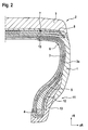
- the Fig. 2 shows a half cross-section through another car tire according to the invention.
- the passenger tire of the Fig. 2 differs from the car tire of the Fig. 1 in that the single-layer carcass 3 has a so-called C-layer construction.
- the carcass turnup 3a is guided over the entire height of the side wall 1 and the end of the carcass bump 3a lies under the belt 7.
- the shore A hardnesses in the bead area 2 correspond to those of variant 3 of the table.
- the Fig. 3 shows a half cross-section through another passenger car tire according to the invention.
- the passenger tire of the Fig. 3 differs from the car tire of the Fig. 1 in that, in addition to the carcass ply 3, a second carcass ply 14 resting radially on the outside of the carcass ply 3 is arranged.
- the second carcass ply 14 passes through the crown area 2 and the side walls 1, rests on the carcass turnup 3a of the first carcass ply 3, does not run around the bead cores 4, but terminates at height this.
- the Shore A hardnesses in the bead area 11 correspond to those of variant 3 of the table.
- the Fig. 4 shows a half cross section through another further inventive car tire.
- the passenger tire of the Fig. 4 differs from the car tire of the Fig. 4 in that instead of the bead amplifier the Fig. 3 a cushion strip 15 is arranged and that the Shore A hardnesses in the bead area 2 correspond to those of variant 3 of the table.
Landscapes
- Engineering & Computer Science (AREA)
- Mechanical Engineering (AREA)
- Tires In General (AREA)
Abstract
Description
- Die Erfindung betrifft einen Fahrzeugluftreifen für einen PKW, Van oder Light Truck mit einer Radialkarkasse und mit zwei Wulstbereichen, welche wenigstens je einen Wulstkern, einen dem Wulstkern aufsitzenden Wulstkernreiter und einen den Wulstbereich nach axial außen begrenzenden Wulststreifen aufweisen, wobei die Radialkarkasse von axial innen nach axial außen um die Wulstkerne geführt ist und in einem Karkasshochschlag endet und wobei die im Wulstbereich angeordneten Bauteile Wulstkernreiter, Radialkarkasse und Wulststreifen bestimmte Shore A-Härten aufweisen.
- Kautschukmischungen von Reifenbauteilen weisen bestimmte Shore A-Härten auf. Höhere Shore A-Härten beschreiben härtere Kautschukmischungen, während niedrigere Shore A-Härten weichere Kautschukmischungen beschreiben.
- Der Aufbau eines Wulstes für PKW-, Van- oder Light Truck-Reifen ist dem Fachmann hinreichend bekannt.
- Aus der
DE 1 964 575 A ist ein PKW-Reifen bekannt geworden, der besonders gestaltete Wulstbereiche aufweist, um bei Überlastbedingungen einen Ausfall des Reifens im Bereich des Wulstes zu vermeiden. In der vorgenannten Druckschrift wird beschrieben, dass die im Wulstbereich angeordneten Bauteile eine glatte Veränderung der Steifigkeit aufweisen, d.h., dass eine graduelle Abnahme der Steifigkeit vom Bereich der Wülste in Richtung auf die Seitenwandbereiche erfolgt. Über konkrete Werte der Abnahme der Steifigkeit in Bezug auf die im Wulstbereich angeordneten Bauteile schweigt sich die vorgenannte Druckschrift jedoch aus. - Bei schwierigen Straßen- und/ oder Ausladungsverhältnissen, den sogenannten "overload"-Bedingungen, neigt besonders der Wulstbereich des Reifens zu mechanischen Ausfallerscheinungen. Bisher begegnet man diesem mechanischen Ausfall damit, zur Verstärkung des Wulstbereiches zusätzliche Verstärkungslagen in diesen einzubringen. Jedoch ist hierdurch der Rollwiderstand des Reifens nachteilig beeinflusst. Zudem steigt die Gefahr des thermisch bedingten Ausfalls des Reifens.
- Es ist die Aufgabe der Erfindung, einen Fahrzeug(luft-)reifen für PKWs, Vans oder Light Trucks zur Verfügung zu stellen, der auch bei schwierigen Straßen- und/ oder Ausladungsverhältnissen eine verbesserte Haltbarkeit aufweist und der verringert zu einem mechanischen und thermischen Ausfall neigt.
- Die Aufgabe wird gelöst, indem die Shore A-Härte von axial unmittelbar benachbart im Wulstbereich angeordneten Bauteilen nicht mehr als 5 Shore A-Härtepunkte voneinander abweicht.
- Wenn die Shore A-Härte eines Bauteiles beschrieben wird, ist immer die Shore A-Härte der Kautschukmischung dieses Bauteiles gemeint. Dabei kann das Bauteil vollständig aus einer oder mehreren Kautschukmischung bestehen oder das Bauteil kann eine gummierte Festigkeitsträger aufweisende Lage sein.
- Erfindungsgemäß ist ein Fahrzeugreifen für PKWs, Vans oder Light Trucks zur Verfügung gestellt, der auch bei sogenannten overload-Bedingungen eine verbesserte Haltbarkeit aufweist. Dabei ist wesentlich, dass diese verbesserte Haltbarkeit nicht durch den Einsatz von zusätzlichen Verstärkungslagen im Wulstbereich erzielt ist. Im Gegenteil: lediglich die Kautschukmischungen der bereits im Stand der Technik im Wulst eingesetzten Bauteile sind in Bezug auf ihre Shore A-Härten optimiert. Dabei weisen zwei axial nebeneinander angeordnete Bauteile im Wulstbereich Shore A-Härten auf, die nicht mehr als 5 Shore A-Härtepunkte voneinander abweichen. Die Erfindung ist daher ohne Konstruktionsanpassungen auf heute bereits eingesetzte Reifen anwendbar. Die Erfinder vermuten, dass der vorteilhafte erfindungsgemäße Effekt durch eine Verminderung von Steifigkeitssprüngen im Wulstbereich bedingt ist. Bei der Einfederung des Reifens unter hoher Last wird die Seitenwand verformt, der untere Seitenwandbereich wird um das Felgenhorn gebogen und die Reifenbauteile in der unteren Seitenwand werden einer Scherbelastung ausgesetzt. Bei entsprechend hoher Geschwindigkeit im Betrieb ergibt sich eine sehr dynamische, schwellende bis wechselnde Belastung. Die gleichmäßige Verteilung der Steifigkeit aller Bauteile führt dazu, daß bei der Verformung (Scherung) der Seitenwand kein Bauteil die Hauptlast der Verformung (Scherung) übernehmen muß und dann unter dieser Belastung ausfällt, während angrenzende Bauteile weit unter ihrer Belastungsgrenze verformt (geschert) werden.
- Die Shore A-Härte wird ermittelt nach DIN ISO 7619.
- "Axial benachbarte Bauteile" meint Bauteile, die - in axialer Richtung des Fahrzeugreifens betrachtet - nebeneinander angeordnet sind.
- "Wulstverstärker" meint eine gummierte Festigkeitsträger aufweisende Lage, welche im Wulstbereich axial außen in Bezug auf den Karkasshochschlag angeordnet ist und den Wulstkern nicht umläuft.
- "Polsterstreifen" meint eine vollständig aus Kautschuk bestehende Lage, welche im Wulstbereich axial außen in Bezug auf den Karkasshochschlag angeordnet ist und den Wulstkern nicht umläuft.
- In einer Ausführung der Erfindung sind die Shore A-Härten von axial benachbart im Wulstbereich angeordneten Bauteilen, beginnend vom Wulstkernreiter zur Außenseite der Seitenwand hin, steigend. Das bedeutet, dass unmittelbar benachbarte Bauteile gleiche oder innerhalb von 5 Punkten steigende Shore A-Härten aufweisen können. Wesentlich ist, dass die Shore A-Härten vom Wulstkernreiter zur Außenseite der Seitenwand hin steigend sind - in dem Sinne, dass der Wulstkernreiter eine niedrigere Shore A-Härte als der Wulststreifen, der axial außen in Bezug auf den Wulstkernreiter angeordnet ist, aufweist.
- In einer anderen Ausführung der Erfindung sind die Shore A-Härten von axial benachbart im Wulstbereich angeordneten Bauteilen, beginnend vom Wulstkernreiter zur Außenseite der Seitenwand fallend, bevorzugt, dass der Wulstkernreiter eine Härte von 80 Shore A aufweist und der Wulststreifen eine Härte von 75 Shore A aufweist, oder bevorzugt, dass der Wulstkernreiter eine Härte von 70 Shore A aufweist und der Wulststreifen eine Härte von 60 Shore A aufweist. Das bedeutet, dass unmittelbar benachbarte Bauteile gleiche oder innerhalb von 5 Punkten fallende Shore A-Härten aufweisen können. Wesentlich ist, dass die Shore A-Härten vom Wulstkernreiter zur Außenseite der Seitenwand hin fallend sind - in dem Sinne, dass der Wulstkernreiter eine größere Shore A-Härte als der Wulststreifen, der axial außen in Bezug auf den Wulstkernreiter angeordnet ist, aufweist.
- In einer wiederum anderen Ausführung der Erfindung liegen alle Shore A-Härten von im Wulstbereich angeordneten Bauteilen, beginnend vom Wulstkernreiter zur Außenseite der Seitenwand hin, in einem Größenbereich von +/- 5 Shore A-Härtepunkten.
- Vorteilhaft ist es, wenn die Radialkarkasse ein- oder zweilagig ausgeführt ist, wobei bei der zweilagigen Ausführung vorzugsweise beide Lagen die gleiche Shore A-Härte aufweisen.
- Die einlagige Radialkarkasse weist eine übliche, in einem Karkasshochschlag endende Konstruktion auf, wobei das Ende des Karkasshochschlages vorzugsweise auf Höhe der Seitenwand oberhalb des oberen Endes des Wulstkernreiters und unterhalb und entfernt von dem Gürtel liegt oder weist vorzugsweise eine sogenannte "C-Lagenkonstruktion" auf, bei das Ende des Karkasshochschlages die komplette Reifenseitenwand hochgeführt ist und bis unter die Gürtelkanten reicht.
- Die zweilagige Radialkarkasse weist eine einlagige Radialkarkassenkonstruktion auf, bei der der Karkasshochschlag um die Kerne von innen nach außen herumgeführt ist und bei der das Ende des Karkasshochschlages auf Höhe der Seitenwand oberhalb des oberen Endes des Wulstkernreiters liegt und bei der eine zweite Karkasslage radial außen auf der ersten Karkasslage aufgebracht ist, die jedoch den Karkasshochschlag der ersten Karkasslage abdeckt und die Wulstkerne nicht umläuft, sondern auf Höhe des Wulstkernes endet.
- Die nachfolgend aufgeführten Ausführungsbeispiele weisen eine der vorgenannten Karkasskonstruktionen auf.
- Zweckmäßig ist es, wenn nur ein Wulstverstärker zwischen der Radialkarkasse und dem Wulststreifen angeordnet ist. Zwischen der Radialkarkasse und dem Wulststreifen ist alleinig ein Wulstverstärker und keine anderen Bauteile angeordnet.
- Zweckmäßig ist es, wenn ein oder zwei Polsterstreifen zwischen dem Wulstverstärker und der Karkasse angeordnet sind. Zwischen der Radialkarkasse und dem Wulstverstärker sind alleinig ein oder zwei Polsterstreifen und keine anderen Bauteile angeordnet.
- Vorteilhaft ist es, wenn zwischen dem Wulststreifen und der Karkasse nur ein einziger oder zwei Posterstreifen angeordnet sind. Zwischen der Radialkarkasse und dem Wulststreifen sind alleinig ein oder zwei Polsterstreifen und keine anderen Bauteile angeordnet.
- Sind zwei Polsterstreifen angeordnet, weisen diese vorteilhafterweise die gleiche Shore A-Härte auf.
- Die nachfolgende Tabelle zeigt fünf Ausführungsvarianten des Wulstbereiches eines erfindungsgemäßen PKW-,Van- oder Lighttruck-Reifens. Die Bauteile sind von links nach rechts entsprechend ihrer Anordnung im rechten Wulstbereich des Reifensquerschnittes von Apex in Richtung Außenseite des Reifens aufgeführt. Das Kreuz gibt an, dass dieses Bauteil vorhanden/ verwirklicht ist, die Zahl neben dem Kreuz gibt die Shore A-Härte des betreffenden Bauteiles an. "-" gibt an, dass das betreffende Bauteil nicht vorhanden/verwirklicht ist.
Tabelle Variante Wulstkernreiter Karkasse Polstersteifen 1 Polsterstreifen 2 Wulstverstärker Wulststreifen 1 X 80 X 75 X 75 - X 75 X 75 2 X 70 X 65 X 65 - X 65 X 60 3 X 80 X 75 X 75 - - X 75 4 X 80 X 75 X 75 X 75 - X 75 5 X 80 X 75 - - X 75 X 75 - Weitere Merkmale, Vorteile und Einzelheiten der Erfindung werden nun anhand von Zeichnungen, die schematische Ausführungsbeispiele darstellen, näher erläutert. Dabei zeigen die
-
Fig. 1 einen hälftigen Querschnitt durch einen erfindungsgemäßen PKW-Reifen; -
Fig. 2 einen hälftigen Querschnitt durch einen anderen erfindungsgemäßen PKW-Reifen; -
Fig. 3 einen hälftigen Querschnitt durch einen weiteren erfindungsgemäßen PKW-Reifen; -
Fig. 4 einen hälftigen Querschnitt durch einen anderen weiteren erfindungsgemäßen PKW-Reifen. - Die
Fig. 1 zeigt einen hälftigen Querschnitt eines erfindungsgemäßen Fahrzeugluftreifens, hier eines PKW-Luftreifens radialer Bauart. Der Reifen weist eine übliche Standardkonstruktion auf, mit zwei Seitenwänden 1, einem Kronenbereich 2, mit einer Karkasse aus einer Karkasslage 3, welche die Wulstkerne 4 und die den Wulstkernen 4 aufsitzenden Wulstkernreiter 5 von axial innen nach axial außen umläuft und in einem Karkasshochschlag 3a endet, mit einer luftdicht ausgeführten Innenschicht 6, einem zweilagigen Gürtel 7, welcher durch eine Gürtelbandage 8 abgedeckt ist und einem Laufstreifen 9. Das Ende des Karkasshochschlages 10 liegt oberhalb des Wulstkernreiters 5 auf Höhe der Seitenwand 1. - Der Wulstbereich 11 besteht -vom Wulstkernreiter 5 betrachtet nach axial außen- aus den folgenden Bauteilen: Wulstkernreiter 5, Karkasshochschlag 3a, Wulstverstärker12 und Wulststreifen 13. Der Wulstverstärker 12 weist textile Festigkeitsträger auf und beginnt mit seinem unteren Ende auf Höhe des Wulstkernes und reicht mit seinem oberen Ende bis in das obere Drittel des Wulstkernreiters 5.
- Die Shore A-Härten von den axial benachbart im Wulstbereich 1 angeordneten Bauteilen 5, 3a, 12, 13 entsprechen denen der in der Tabelle, Variante 5 dargestellten Härten: Wulstkernreiter 5: 80 Shore A, Karkasshochschlag (Karkasse): 75 Shore A, Wulsterstärker: 75 Shore A, Wulststreifen: 75 Shore A. Die Shore A-Härte von axial unmittelbar benachbart im Wulstbereich 11 angeordneten Bauteilen weicht nicht mehr als 5 Shore A-Härtepunkte voneinander ab und die Shore A-Härten von axial benachbart im Wulstbereich 11 angeordneten Bauteilen beginnend vom Wulstkernreiter 5 zur Außenseite der Seitenwand 1 sind fallend.
- Die
Fig. 2 zeigt einen hälftigen Querschnitt durch einen anderen erfindungsgemäßen PKW-Reifen. Der PKW-Reifen derFig. 2 unterscheidet sich darin von dem PKW-Reifen derFig. 1 , dass die einlagige Karkasse 3 eine sogenannte C-Lagenkonstruktion aufweist. Bei einer C-Lagenkonstruktion ist der Karkasshochschlag 3a über die gesamte Höhe der Seitenwand 1 geführt und das Ende des Karkasshochschlages 3a liegt unter dem Gürtel 7. Die Shore A-Härten im Wulstbereich 2 entsprechen denen der Variante 3 der Tabelle. - Die
Fig. 3 zeigt einen hälftigen Querschnitt durch einen weiteren erfindungsgemäßen PKW-Reifen. Der PKW-Reifen derFig. 3 unterscheidet sich darin von dem PKW-Reifen derFig. 1 , dass zusätzlich zu der Karkasslage 3 eine zweite, radial außen auf der Karkasslage 3 aufliegende Karkasslage 14 angeordnet ist. Die zweite Karkasslage 14 durchläuft den Kronenbereich 2 und die Seitenwände 1, liegt auf dem Karkasshochschlag 3a der ersten Karkasslage 3 auf, umläuft die Wulstkerne 4 nicht, sondern endet auf Höhe dieser. Die Shore A-Härten im Wulstbereich 11 entsprechen denen der Variante 3 der Tabelle. - Die
Fig. 4 zeigt einen hälftigen Querschnitt durch einen anderen weiteren erfindungsgemäßen PKW-Reifen. Der PKW-Reifen derFig. 4 unterscheidet sich darin von dem PKW-Reifen derFig. 4 , dass anstatt des Wulstverstärkers derFig. 3 ein Polsterstreifen 15 angeordnet ist und dass die Shore A-Härten im Wulstbereich 2 denen der Variante 3 der Tabelle entsprechen. -
- 1
- Seitenwand
- 2
- Kronenbereich
- 3
- Karkasslage
- 3a
- Karkasshochschlag
- 4
- Wulstkern
- 5
- Wulstkernreiter
- 6
- Innenschicht
- 7
- Gürtel
- 8
- Gürtelbandage
- 9
- Laufstreifen
- 10
- Ende des Karkasshochschlages
- 11
- Wulstbereich
- 12
- Wulstverstärker
- 13
- Wulststreifen
- 14
- Zweite Karkasslage
- 15
- Polsterstreifen
- rR
- radiale Richtung
- aR
- axiale Richtung
Claims (9)
- Fahrzeugluftreifen für einen PKW, Van oder Light Truck mit einer Radialkarkasse (3, 3a, 14) und mit zwei Wulstbereichen (11), welche wenigstens je einen Wulstkern (4), einen dem Wulstkern (4) aufsitzenden Wulstkernreiter (5) und einen den Wulstbereich (11) nach axial außen begrenzenden Wulststreifen (13) aufweisen, wobei die Radialkarkasse (3, 14) von axial innen nach axial außen um die Wulstkerne (4) geführt ist und in einem Karkasshochschlag (3a) endet und wobei die im Wulstbereich (11) angeordneten Bauteile Wulstkernreiter (5), Radialkarkasse (3, 3a, 14) und Wulststreifen (13) bestimmte Shore A-Härten aufweisen,
dadurch gekennzeichnet, dass die Shore A-Härte von axial unmittelbar benachbart im Wulstbereich (11) angeordneten Bauteilen (3, 3a, 14, 12, 13, 14, 15) nicht mehr als 5 Shore A-Härtepunkte voneinander abweicht. - Fahrzeugluftreifen nach Anspruch 1, dadurch gekennzeichnet, dass die Shore A-Härten von axial benachbart im Wulstbereich (11) angeordneten Bauteilen (3, 3a, 14, 12, 13, 14, 15) beginnend vom Wulstkernreiter (5) zur Außenseite der Seitenwand (1) steigend sind.
- Fahrzeugluftreifen nach Anspruch 1, dadurch gekennzeichnet, dass die Shore A-Härten von axial benachbart im Wulstbereich (11) angeordneten Bauteilen (3, 3a, 14, 12, 13, 14, 15), beginnend vom Wulstkernreiter (5) zur Außenseite der Seitenwand (1) fallend sind, bevorzugt, dass der Wulstkernreiter (5) eine Härte von 80 Shore A aufweist und der Wulststreifen (13) eine Härte von 75 Shore A aufweist, oder bevorzugt, dass der Wulstkernreiter (5) eine Härte von 70 Shore A aufweist und der Wulststreifen (13) eine Härte von 60 Shore A aufweist.
- Fahrzeugluftreifen nach Anspruch 1, dadurch gekennzeichnet, dass die Shore A-Härten von allen im Wulstbereich (11) angeordneten Bauteilen (3, 3a, 14, 12, 13, 14, 15), beginnend vom Wulstkernreiter (5) zur Außenseite der Seitenwand (1) hin, in einem Größenbereich von +/- 5 Shore A-Härtepunkten liegen, vorzugsweise in einem Härtebereich von 80 - 75 Shore A.
- Fahrzeugluftreifen nach Anspruch 1 oder einem der Ansprüche 2 bis 4, dadurch gekennzeichnet, dass die Radialkarkasse (3, 14) ein- oder zweilagig ausgeführt ist, wobei bei der zweilagigen Ausführung vorzugsweise beide Lagen (3, 14) die gleiche Shore A-Härte aufweisen.
- Fahrzeugluftreifen nach Anspruch 1 oder 5 oder einem der Ansprüche 2 bis 4, dadurch gekennzeichnet, dass nur ein Wulstverstärker (12) zwischen der Radialkarkasse (3, 14) und dem Wulststreifen (13) angeordnet ist.
- Fahrzeugluftreifen nach Anspruch 1, 5 oder 6 oder einem der Ansprüche 2 bis 4, dadurch gekennzeichnet, dass ein oder zwei Polsterstreifen (15) zwischen dem Wulstverstärker (12) und der Karkasse (3, 14) angeordnet sind.
- Fahrzeugluftreifen nach Anspruch 1,5,6 oder 7 oder einem der Ansprüche 2 bis 4, dadurch gekennzeichnet, dass zwischen dem Wulststreifen (13) und der Karkasse (3, 14) nur ein einziger Posterstreifen (15) angeordnet ist.
- Fahrzeugluftreifen nach Anspruch 1, 5 oder 6 oder einem der Ansprüche 2 bis 4, dadurch gekennzeichnet, dass nur ein oder zwei Polsterstreifen (15) zwischen dem Wulststreifen (13) und der Karkasse (3, 14) angeordnet sind.
Applications Claiming Priority (1)
| Application Number | Priority Date | Filing Date | Title |
|---|---|---|---|
| DE102014221312.6A DE102014221312A1 (de) | 2014-10-21 | 2014-10-21 | Fahrzeugluftreifen |
Publications (2)
| Publication Number | Publication Date |
|---|---|
| EP3012123A1 true EP3012123A1 (de) | 2016-04-27 |
| EP3012123B1 EP3012123B1 (de) | 2019-07-10 |
Family
ID=53773366
Family Applications (1)
| Application Number | Title | Priority Date | Filing Date |
|---|---|---|---|
| EP15179617.4A Active EP3012123B1 (de) | 2014-10-21 | 2015-08-04 | Fahrzeugluftreifen |
Country Status (2)
| Country | Link |
|---|---|
| EP (1) | EP3012123B1 (de) |
| DE (1) | DE102014221312A1 (de) |
Cited By (3)
| Publication number | Priority date | Publication date | Assignee | Title |
|---|---|---|---|---|
| JP2020055337A (ja) * | 2018-09-28 | 2020-04-09 | 株式会社ブリヂストン | タイヤ |
| EP4253094A1 (de) * | 2022-03-31 | 2023-10-04 | Sumitomo Rubber Industries, Ltd. | Luftreifen |
| EP4335660A1 (de) * | 2022-09-08 | 2024-03-13 | Continental Reifen Deutschland GmbH | Fahrzeugreifenkonstruktion |
Families Citing this family (2)
| Publication number | Priority date | Publication date | Assignee | Title |
|---|---|---|---|---|
| CN111163948A (zh) * | 2017-10-02 | 2020-05-15 | 米其林集团总公司 | 具有增强的下部区域的轮胎 |
| EP3680114B1 (de) | 2019-01-10 | 2021-09-22 | Continental Reifen Deutschland GmbH | Fahrzeugluftreifen |
Citations (4)
| Publication number | Priority date | Publication date | Assignee | Title |
|---|---|---|---|---|
| DE1964575A1 (de) | 1968-12-31 | 1970-07-09 | Uniroyal Englebert France | Radialreifen |
| WO2014042035A1 (ja) * | 2012-09-14 | 2014-03-20 | 横浜ゴム株式会社 | ランフラットタイヤ |
| EP2740615A1 (de) * | 2012-12-10 | 2014-06-11 | Continental Reifen Deutschland GmbH | Fahrzeugluftreifen |
| WO2014156283A1 (ja) * | 2013-03-26 | 2014-10-02 | 住友ゴム工業株式会社 | 空気入りタイヤ |
-
2014
- 2014-10-21 DE DE102014221312.6A patent/DE102014221312A1/de not_active Withdrawn
-
2015
- 2015-08-04 EP EP15179617.4A patent/EP3012123B1/de active Active
Patent Citations (6)
| Publication number | Priority date | Publication date | Assignee | Title |
|---|---|---|---|---|
| DE1964575A1 (de) | 1968-12-31 | 1970-07-09 | Uniroyal Englebert France | Radialreifen |
| WO2014042035A1 (ja) * | 2012-09-14 | 2014-03-20 | 横浜ゴム株式会社 | ランフラットタイヤ |
| DE112013002460T5 (de) * | 2012-09-14 | 2015-02-26 | The Yokohama Rubber Co., Ltd. | Notlaufreifen |
| EP2740615A1 (de) * | 2012-12-10 | 2014-06-11 | Continental Reifen Deutschland GmbH | Fahrzeugluftreifen |
| WO2014156283A1 (ja) * | 2013-03-26 | 2014-10-02 | 住友ゴム工業株式会社 | 空気入りタイヤ |
| EP2974891A1 (de) * | 2013-03-26 | 2016-01-20 | Sumitomo Rubber Industries, Ltd. | Luftreifen |
Cited By (5)
| Publication number | Priority date | Publication date | Assignee | Title |
|---|---|---|---|---|
| JP2020055337A (ja) * | 2018-09-28 | 2020-04-09 | 株式会社ブリヂストン | タイヤ |
| EP4253094A1 (de) * | 2022-03-31 | 2023-10-04 | Sumitomo Rubber Industries, Ltd. | Luftreifen |
| JP2023151038A (ja) * | 2022-03-31 | 2023-10-16 | 住友ゴム工業株式会社 | 空気入りタイヤ |
| US12194785B2 (en) | 2022-03-31 | 2025-01-14 | Sumitomo Rubber Industries, Ltd. | Pneumatic tire |
| EP4335660A1 (de) * | 2022-09-08 | 2024-03-13 | Continental Reifen Deutschland GmbH | Fahrzeugreifenkonstruktion |
Also Published As
| Publication number | Publication date |
|---|---|
| EP3012123B1 (de) | 2019-07-10 |
| DE102014221312A1 (de) | 2016-04-21 |
Similar Documents
| Publication | Publication Date | Title |
|---|---|---|
| DE602004005774T2 (de) | Radialer Luftreifen | |
| DE112017003870B4 (de) | Notlaufreifen | |
| EP3012123B1 (de) | Fahrzeugluftreifen | |
| DE69713715T2 (de) | Luftreifen | |
| DE112017006369B4 (de) | Notlaufreifen | |
| DE112013002477T5 (de) | Luftreifen | |
| DE2655389A1 (de) | Guertelreifen-felgenanordnung | |
| DE102013205054A1 (de) | Luftreifen | |
| DE3122190A1 (de) | Luftreifen mit radialkarkasse fuer lastfahrzeuge | |
| DE102012217331A1 (de) | Notlaufluftreifen | |
| EP1970221B1 (de) | Fahrzeugluftreifen mit Notlaufeigenschaften | |
| DE60108020T2 (de) | Notlaufreifen | |
| EP3088209B1 (de) | Fahrzeugluftreifen | |
| DE69513592T2 (de) | Radialer Luftreifen | |
| DE102019113682A1 (de) | Schwerlast-Luftreifen | |
| EP2740615B1 (de) | Fahrzeugluftreifen | |
| EP0881105B1 (de) | Fahrzeugluftreifen | |
| DE112018006272B4 (de) | Luftreifen | |
| EP3061627B1 (de) | Nutzfahrzeugreifen mit niedriger querschnittshöhe | |
| DE10119056A1 (de) | Gürtelreifen mit Seitenwandverstärkung | |
| EP2979905B1 (de) | Fahrzeugluftreifen | |
| DE112012007276T5 (de) | Luftreifen | |
| EP2114700B1 (de) | Fahrzeugluftreifen mit notlaufeigenschaften | |
| EP3041690B1 (de) | Fahrzeugluftreifen | |
| DE102013105581A1 (de) | Fahrzeugluftreifen mit Notlaufeigenschaften |
Legal Events
| Date | Code | Title | Description |
|---|---|---|---|
| PUAI | Public reference made under article 153(3) epc to a published international application that has entered the european phase |
Free format text: ORIGINAL CODE: 0009012 |
|
| AK | Designated contracting states |
Kind code of ref document: A1 Designated state(s): AL AT BE BG CH CY CZ DE DK EE ES FI FR GB GR HR HU IE IS IT LI LT LU LV MC MK MT NL NO PL PT RO RS SE SI SK SM TR |
|
| AX | Request for extension of the european patent |
Extension state: BA ME |
|
| STAA | Information on the status of an ep patent application or granted ep patent |
Free format text: STATUS: REQUEST FOR EXAMINATION WAS MADE |
|
| 17P | Request for examination filed |
Effective date: 20161027 |
|
| RBV | Designated contracting states (corrected) |
Designated state(s): AL AT BE BG CH CY CZ DE DK EE ES FI FR GB GR HR HU IE IS IT LI LT LU LV MC MK MT NL NO PL PT RO RS SE SI SK SM TR |
|
| RIC1 | Information provided on ipc code assigned before grant |
Ipc: B60C 15/06 20060101ALN20190214BHEP Ipc: B60C 15/00 20060101AFI20190214BHEP |
|
| GRAP | Despatch of communication of intention to grant a patent |
Free format text: ORIGINAL CODE: EPIDOSNIGR1 |
|
| STAA | Information on the status of an ep patent application or granted ep patent |
Free format text: STATUS: GRANT OF PATENT IS INTENDED |
|
| RIC1 | Information provided on ipc code assigned before grant |
Ipc: B60C 15/06 20060101ALN20190218BHEP Ipc: B60C 15/00 20060101AFI20190218BHEP |
|
| INTG | Intention to grant announced |
Effective date: 20190326 |
|
| GRAS | Grant fee paid |
Free format text: ORIGINAL CODE: EPIDOSNIGR3 |
|
| GRAA | (expected) grant |
Free format text: ORIGINAL CODE: 0009210 |
|
| STAA | Information on the status of an ep patent application or granted ep patent |
Free format text: STATUS: THE PATENT HAS BEEN GRANTED |
|
| AK | Designated contracting states |
Kind code of ref document: B1 Designated state(s): AL AT BE BG CH CY CZ DE DK EE ES FI FR GB GR HR HU IE IS IT LI LT LU LV MC MK MT NL NO PL PT RO RS SE SI SK SM TR |
|
| REG | Reference to a national code |
Ref country code: GB Ref legal event code: FG4D Free format text: NOT ENGLISH |
|
| REG | Reference to a national code |
Ref country code: CH Ref legal event code: EP Ref country code: AT Ref legal event code: REF Ref document number: 1153152 Country of ref document: AT Kind code of ref document: T Effective date: 20190715 |
|
| REG | Reference to a national code |
Ref country code: IE Ref legal event code: FG4D Free format text: LANGUAGE OF EP DOCUMENT: GERMAN |
|
| REG | Reference to a national code |
Ref country code: DE Ref legal event code: R096 Ref document number: 502015009578 Country of ref document: DE |
|
| REG | Reference to a national code |
Ref country code: NL Ref legal event code: MP Effective date: 20190710 |
|
| REG | Reference to a national code |
Ref country code: LT Ref legal event code: MG4D |
|
| PG25 | Lapsed in a contracting state [announced via postgrant information from national office to epo] |
Ref country code: SE Free format text: LAPSE BECAUSE OF FAILURE TO SUBMIT A TRANSLATION OF THE DESCRIPTION OR TO PAY THE FEE WITHIN THE PRESCRIBED TIME-LIMIT Effective date: 20190710 Ref country code: HR Free format text: LAPSE BECAUSE OF FAILURE TO SUBMIT A TRANSLATION OF THE DESCRIPTION OR TO PAY THE FEE WITHIN THE PRESCRIBED TIME-LIMIT Effective date: 20190710 Ref country code: FI Free format text: LAPSE BECAUSE OF FAILURE TO SUBMIT A TRANSLATION OF THE DESCRIPTION OR TO PAY THE FEE WITHIN THE PRESCRIBED TIME-LIMIT Effective date: 20190710 Ref country code: PT Free format text: LAPSE BECAUSE OF FAILURE TO SUBMIT A TRANSLATION OF THE DESCRIPTION OR TO PAY THE FEE WITHIN THE PRESCRIBED TIME-LIMIT Effective date: 20191111 Ref country code: LT Free format text: LAPSE BECAUSE OF FAILURE TO SUBMIT A TRANSLATION OF THE DESCRIPTION OR TO PAY THE FEE WITHIN THE PRESCRIBED TIME-LIMIT Effective date: 20190710 Ref country code: NL Free format text: LAPSE BECAUSE OF FAILURE TO SUBMIT A TRANSLATION OF THE DESCRIPTION OR TO PAY THE FEE WITHIN THE PRESCRIBED TIME-LIMIT Effective date: 20190710 Ref country code: BG Free format text: LAPSE BECAUSE OF FAILURE TO SUBMIT A TRANSLATION OF THE DESCRIPTION OR TO PAY THE FEE WITHIN THE PRESCRIBED TIME-LIMIT Effective date: 20191010 Ref country code: NO Free format text: LAPSE BECAUSE OF FAILURE TO SUBMIT A TRANSLATION OF THE DESCRIPTION OR TO PAY THE FEE WITHIN THE PRESCRIBED TIME-LIMIT Effective date: 20191010 |
|
| PG25 | Lapsed in a contracting state [announced via postgrant information from national office to epo] |
Ref country code: AL Free format text: LAPSE BECAUSE OF FAILURE TO SUBMIT A TRANSLATION OF THE DESCRIPTION OR TO PAY THE FEE WITHIN THE PRESCRIBED TIME-LIMIT Effective date: 20190710 Ref country code: ES Free format text: LAPSE BECAUSE OF FAILURE TO SUBMIT A TRANSLATION OF THE DESCRIPTION OR TO PAY THE FEE WITHIN THE PRESCRIBED TIME-LIMIT Effective date: 20190710 Ref country code: IS Free format text: LAPSE BECAUSE OF FAILURE TO SUBMIT A TRANSLATION OF THE DESCRIPTION OR TO PAY THE FEE WITHIN THE PRESCRIBED TIME-LIMIT Effective date: 20191110 Ref country code: LV Free format text: LAPSE BECAUSE OF FAILURE TO SUBMIT A TRANSLATION OF THE DESCRIPTION OR TO PAY THE FEE WITHIN THE PRESCRIBED TIME-LIMIT Effective date: 20190710 Ref country code: RS Free format text: LAPSE BECAUSE OF FAILURE TO SUBMIT A TRANSLATION OF THE DESCRIPTION OR TO PAY THE FEE WITHIN THE PRESCRIBED TIME-LIMIT Effective date: 20190710 Ref country code: GR Free format text: LAPSE BECAUSE OF FAILURE TO SUBMIT A TRANSLATION OF THE DESCRIPTION OR TO PAY THE FEE WITHIN THE PRESCRIBED TIME-LIMIT Effective date: 20191011 |
|
| PG25 | Lapsed in a contracting state [announced via postgrant information from national office to epo] |
Ref country code: TR Free format text: LAPSE BECAUSE OF FAILURE TO SUBMIT A TRANSLATION OF THE DESCRIPTION OR TO PAY THE FEE WITHIN THE PRESCRIBED TIME-LIMIT Effective date: 20190710 |
|
| PG25 | Lapsed in a contracting state [announced via postgrant information from national office to epo] |
Ref country code: IT Free format text: LAPSE BECAUSE OF FAILURE TO SUBMIT A TRANSLATION OF THE DESCRIPTION OR TO PAY THE FEE WITHIN THE PRESCRIBED TIME-LIMIT Effective date: 20190710 Ref country code: RO Free format text: LAPSE BECAUSE OF FAILURE TO SUBMIT A TRANSLATION OF THE DESCRIPTION OR TO PAY THE FEE WITHIN THE PRESCRIBED TIME-LIMIT Effective date: 20190710 Ref country code: DK Free format text: LAPSE BECAUSE OF FAILURE TO SUBMIT A TRANSLATION OF THE DESCRIPTION OR TO PAY THE FEE WITHIN THE PRESCRIBED TIME-LIMIT Effective date: 20190710 Ref country code: EE Free format text: LAPSE BECAUSE OF FAILURE TO SUBMIT A TRANSLATION OF THE DESCRIPTION OR TO PAY THE FEE WITHIN THE PRESCRIBED TIME-LIMIT Effective date: 20190710 Ref country code: PL Free format text: LAPSE BECAUSE OF FAILURE TO SUBMIT A TRANSLATION OF THE DESCRIPTION OR TO PAY THE FEE WITHIN THE PRESCRIBED TIME-LIMIT Effective date: 20190710 |
|
| PG25 | Lapsed in a contracting state [announced via postgrant information from national office to epo] |
Ref country code: MC Free format text: LAPSE BECAUSE OF FAILURE TO SUBMIT A TRANSLATION OF THE DESCRIPTION OR TO PAY THE FEE WITHIN THE PRESCRIBED TIME-LIMIT Effective date: 20190710 Ref country code: CH Free format text: LAPSE BECAUSE OF NON-PAYMENT OF DUE FEES Effective date: 20190831 Ref country code: LU Free format text: LAPSE BECAUSE OF NON-PAYMENT OF DUE FEES Effective date: 20190804 Ref country code: IS Free format text: LAPSE BECAUSE OF FAILURE TO SUBMIT A TRANSLATION OF THE DESCRIPTION OR TO PAY THE FEE WITHIN THE PRESCRIBED TIME-LIMIT Effective date: 20200224 Ref country code: LI Free format text: LAPSE BECAUSE OF NON-PAYMENT OF DUE FEES Effective date: 20190831 Ref country code: SM Free format text: LAPSE BECAUSE OF FAILURE TO SUBMIT A TRANSLATION OF THE DESCRIPTION OR TO PAY THE FEE WITHIN THE PRESCRIBED TIME-LIMIT Effective date: 20190710 Ref country code: SK Free format text: LAPSE BECAUSE OF FAILURE TO SUBMIT A TRANSLATION OF THE DESCRIPTION OR TO PAY THE FEE WITHIN THE PRESCRIBED TIME-LIMIT Effective date: 20190710 Ref country code: CZ Free format text: LAPSE BECAUSE OF FAILURE TO SUBMIT A TRANSLATION OF THE DESCRIPTION OR TO PAY THE FEE WITHIN THE PRESCRIBED TIME-LIMIT Effective date: 20190710 |
|
| REG | Reference to a national code |
Ref country code: BE Ref legal event code: MM Effective date: 20190831 |
|
| REG | Reference to a national code |
Ref country code: DE Ref legal event code: R097 Ref document number: 502015009578 Country of ref document: DE |
|
| PLBE | No opposition filed within time limit |
Free format text: ORIGINAL CODE: 0009261 |
|
| STAA | Information on the status of an ep patent application or granted ep patent |
Free format text: STATUS: NO OPPOSITION FILED WITHIN TIME LIMIT |
|
| PG2D | Information on lapse in contracting state deleted |
Ref country code: IS |
|
| PG25 | Lapsed in a contracting state [announced via postgrant information from national office to epo] |
Ref country code: IE Free format text: LAPSE BECAUSE OF NON-PAYMENT OF DUE FEES Effective date: 20190804 |
|
| 26N | No opposition filed |
Effective date: 20200603 |
|
| PG25 | Lapsed in a contracting state [announced via postgrant information from national office to epo] |
Ref country code: BE Free format text: LAPSE BECAUSE OF NON-PAYMENT OF DUE FEES Effective date: 20190831 Ref country code: SI Free format text: LAPSE BECAUSE OF FAILURE TO SUBMIT A TRANSLATION OF THE DESCRIPTION OR TO PAY THE FEE WITHIN THE PRESCRIBED TIME-LIMIT Effective date: 20190710 |
|
| GBPC | Gb: european patent ceased through non-payment of renewal fee |
Effective date: 20191010 |
|
| PG25 | Lapsed in a contracting state [announced via postgrant information from national office to epo] |
Ref country code: GB Free format text: LAPSE BECAUSE OF NON-PAYMENT OF DUE FEES Effective date: 20191010 |
|
| PG25 | Lapsed in a contracting state [announced via postgrant information from national office to epo] |
Ref country code: CY Free format text: LAPSE BECAUSE OF FAILURE TO SUBMIT A TRANSLATION OF THE DESCRIPTION OR TO PAY THE FEE WITHIN THE PRESCRIBED TIME-LIMIT Effective date: 20190710 |
|
| PG25 | Lapsed in a contracting state [announced via postgrant information from national office to epo] |
Ref country code: MT Free format text: LAPSE BECAUSE OF FAILURE TO SUBMIT A TRANSLATION OF THE DESCRIPTION OR TO PAY THE FEE WITHIN THE PRESCRIBED TIME-LIMIT Effective date: 20190710 Ref country code: HU Free format text: LAPSE BECAUSE OF FAILURE TO SUBMIT A TRANSLATION OF THE DESCRIPTION OR TO PAY THE FEE WITHIN THE PRESCRIBED TIME-LIMIT; INVALID AB INITIO Effective date: 20150804 |
|
| REG | Reference to a national code |
Ref country code: AT Ref legal event code: MM01 Ref document number: 1153152 Country of ref document: AT Kind code of ref document: T Effective date: 20200804 |
|
| PG25 | Lapsed in a contracting state [announced via postgrant information from national office to epo] |
Ref country code: AT Free format text: LAPSE BECAUSE OF NON-PAYMENT OF DUE FEES Effective date: 20200804 |
|
| PG25 | Lapsed in a contracting state [announced via postgrant information from national office to epo] |
Ref country code: MK Free format text: LAPSE BECAUSE OF FAILURE TO SUBMIT A TRANSLATION OF THE DESCRIPTION OR TO PAY THE FEE WITHIN THE PRESCRIBED TIME-LIMIT Effective date: 20190710 |
|
| REG | Reference to a national code |
Ref country code: DE Ref legal event code: R081 Ref document number: 502015009578 Country of ref document: DE Owner name: CONTINENTAL REIFEN DEUTSCHLAND GMBH, DE Free format text: FORMER OWNER: CONTINENTAL REIFEN DEUTSCHLAND GMBH, 30165 HANNOVER, DE |
|
| PGFP | Annual fee paid to national office [announced via postgrant information from national office to epo] |
Ref country code: DE Payment date: 20240831 Year of fee payment: 10 |
|
| PGFP | Annual fee paid to national office [announced via postgrant information from national office to epo] |
Ref country code: FR Payment date: 20240829 Year of fee payment: 10 |
|
| REG | Reference to a national code |
Ref country code: DE Ref legal event code: R119 Ref document number: 502015009578 Country of ref document: DE |