EP3012688A1 - Procede de fabrication d'une structure tridimensionnelle - Google Patents
Procede de fabrication d'une structure tridimensionnelle Download PDFInfo
- Publication number
- EP3012688A1 EP3012688A1 EP15180364.0A EP15180364A EP3012688A1 EP 3012688 A1 EP3012688 A1 EP 3012688A1 EP 15180364 A EP15180364 A EP 15180364A EP 3012688 A1 EP3012688 A1 EP 3012688A1
- Authority
- EP
- European Patent Office
- Prior art keywords
- energy input
- jacket wall
- wall
- input method
- volume
- Prior art date
- Legal status (The legal status is an assumption and is not a legal conclusion. Google has not performed a legal analysis and makes no representation as to the accuracy of the status listed.)
- Granted
Links
Images


Classifications
-
- B—PERFORMING OPERATIONS; TRANSPORTING
- B29—WORKING OF PLASTICS; WORKING OF SUBSTANCES IN A PLASTIC STATE IN GENERAL
- B29C—SHAPING OR JOINING OF PLASTICS; SHAPING OF MATERIAL IN A PLASTIC STATE, NOT OTHERWISE PROVIDED FOR; AFTER-TREATMENT OF THE SHAPED PRODUCTS, e.g. REPAIRING
- B29C64/00—Additive manufacturing, i.e. manufacturing of three-dimensional [3D] objects by additive deposition, additive agglomeration or additive layering, e.g. by 3D printing, stereolithography or selective laser sintering
- B29C64/10—Processes of additive manufacturing
-
- B—PERFORMING OPERATIONS; TRANSPORTING
- B29—WORKING OF PLASTICS; WORKING OF SUBSTANCES IN A PLASTIC STATE IN GENERAL
- B29C—SHAPING OR JOINING OF PLASTICS; SHAPING OF MATERIAL IN A PLASTIC STATE, NOT OTHERWISE PROVIDED FOR; AFTER-TREATMENT OF THE SHAPED PRODUCTS, e.g. REPAIRING
- B29C33/00—Moulds or cores; Details thereof or accessories therefor
- B29C33/38—Moulds or cores; Details thereof or accessories therefor characterised by the material or the manufacturing process
- B29C33/3842—Manufacturing moulds, e.g. shaping the mould surface by machining
-
- B—PERFORMING OPERATIONS; TRANSPORTING
- B29—WORKING OF PLASTICS; WORKING OF SUBSTANCES IN A PLASTIC STATE IN GENERAL
- B29C—SHAPING OR JOINING OF PLASTICS; SHAPING OF MATERIAL IN A PLASTIC STATE, NOT OTHERWISE PROVIDED FOR; AFTER-TREATMENT OF THE SHAPED PRODUCTS, e.g. REPAIRING
- B29C35/00—Heating, cooling or curing, e.g. crosslinking or vulcanising; Apparatus therefor
- B29C35/02—Heating or curing, e.g. crosslinking or vulcanizing during moulding, e.g. in a mould
- B29C35/08—Heating or curing, e.g. crosslinking or vulcanizing during moulding, e.g. in a mould by wave energy or particle radiation
- B29C35/0805—Heating or curing, e.g. crosslinking or vulcanizing during moulding, e.g. in a mould by wave energy or particle radiation using electromagnetic radiation
-
- B—PERFORMING OPERATIONS; TRANSPORTING
- B29—WORKING OF PLASTICS; WORKING OF SUBSTANCES IN A PLASTIC STATE IN GENERAL
- B29C—SHAPING OR JOINING OF PLASTICS; SHAPING OF MATERIAL IN A PLASTIC STATE, NOT OTHERWISE PROVIDED FOR; AFTER-TREATMENT OF THE SHAPED PRODUCTS, e.g. REPAIRING
- B29C64/00—Additive manufacturing, i.e. manufacturing of three-dimensional [3D] objects by additive deposition, additive agglomeration or additive layering, e.g. by 3D printing, stereolithography or selective laser sintering
- B29C64/10—Processes of additive manufacturing
- B29C64/106—Processes of additive manufacturing using only liquids or viscous materials, e.g. depositing a continuous bead of viscous material
- B29C64/124—Processes of additive manufacturing using only liquids or viscous materials, e.g. depositing a continuous bead of viscous material using layers of liquid which are selectively solidified
- B29C64/129—Processes of additive manufacturing using only liquids or viscous materials, e.g. depositing a continuous bead of viscous material using layers of liquid which are selectively solidified characterised by the energy source therefor, e.g. by global irradiation combined with a mask
- B29C64/135—Processes of additive manufacturing using only liquids or viscous materials, e.g. depositing a continuous bead of viscous material using layers of liquid which are selectively solidified characterised by the energy source therefor, e.g. by global irradiation combined with a mask the energy source being concentrated, e.g. scanning lasers or focused light sources
-
- B—PERFORMING OPERATIONS; TRANSPORTING
- B29—WORKING OF PLASTICS; WORKING OF SUBSTANCES IN A PLASTIC STATE IN GENERAL
- B29C—SHAPING OR JOINING OF PLASTICS; SHAPING OF MATERIAL IN A PLASTIC STATE, NOT OTHERWISE PROVIDED FOR; AFTER-TREATMENT OF THE SHAPED PRODUCTS, e.g. REPAIRING
- B29C64/00—Additive manufacturing, i.e. manufacturing of three-dimensional [3D] objects by additive deposition, additive agglomeration or additive layering, e.g. by 3D printing, stereolithography or selective laser sintering
- B29C64/10—Processes of additive manufacturing
- B29C64/141—Processes of additive manufacturing using only solid materials
- B29C64/153—Processes of additive manufacturing using only solid materials using layers of powder being selectively joined, e.g. by selective laser sintering or melting
-
- B—PERFORMING OPERATIONS; TRANSPORTING
- B29—WORKING OF PLASTICS; WORKING OF SUBSTANCES IN A PLASTIC STATE IN GENERAL
- B29C—SHAPING OR JOINING OF PLASTICS; SHAPING OF MATERIAL IN A PLASTIC STATE, NOT OTHERWISE PROVIDED FOR; AFTER-TREATMENT OF THE SHAPED PRODUCTS, e.g. REPAIRING
- B29C64/00—Additive manufacturing, i.e. manufacturing of three-dimensional [3D] objects by additive deposition, additive agglomeration or additive layering, e.g. by 3D printing, stereolithography or selective laser sintering
- B29C64/20—Apparatus for additive manufacturing; Details thereof or accessories therefor
- B29C64/264—Arrangements for irradiation
- B29C64/268—Arrangements for irradiation using laser beams; using electron beams [EB]
- B29C64/273—Arrangements for irradiation using laser beams; using electron beams [EB] pulsed; frequency modulated
-
- B—PERFORMING OPERATIONS; TRANSPORTING
- B29—WORKING OF PLASTICS; WORKING OF SUBSTANCES IN A PLASTIC STATE IN GENERAL
- B29C—SHAPING OR JOINING OF PLASTICS; SHAPING OF MATERIAL IN A PLASTIC STATE, NOT OTHERWISE PROVIDED FOR; AFTER-TREATMENT OF THE SHAPED PRODUCTS, e.g. REPAIRING
- B29C64/00—Additive manufacturing, i.e. manufacturing of three-dimensional [3D] objects by additive deposition, additive agglomeration or additive layering, e.g. by 3D printing, stereolithography or selective laser sintering
- B29C64/20—Apparatus for additive manufacturing; Details thereof or accessories therefor
- B29C64/264—Arrangements for irradiation
- B29C64/277—Arrangements for irradiation using multiple radiation means, e.g. micromirrors or multiple light-emitting diodes [LED]
- B29C64/282—Arrangements for irradiation using multiple radiation means, e.g. micromirrors or multiple light-emitting diodes [LED] of the same type, e.g. using different energy levels
-
- B—PERFORMING OPERATIONS; TRANSPORTING
- B29—WORKING OF PLASTICS; WORKING OF SUBSTANCES IN A PLASTIC STATE IN GENERAL
- B29C—SHAPING OR JOINING OF PLASTICS; SHAPING OF MATERIAL IN A PLASTIC STATE, NOT OTHERWISE PROVIDED FOR; AFTER-TREATMENT OF THE SHAPED PRODUCTS, e.g. REPAIRING
- B29C64/00—Additive manufacturing, i.e. manufacturing of three-dimensional [3D] objects by additive deposition, additive agglomeration or additive layering, e.g. by 3D printing, stereolithography or selective laser sintering
- B29C64/20—Apparatus for additive manufacturing; Details thereof or accessories therefor
- B29C64/295—Heating elements
-
- B—PERFORMING OPERATIONS; TRANSPORTING
- B29—WORKING OF PLASTICS; WORKING OF SUBSTANCES IN A PLASTIC STATE IN GENERAL
- B29C—SHAPING OR JOINING OF PLASTICS; SHAPING OF MATERIAL IN A PLASTIC STATE, NOT OTHERWISE PROVIDED FOR; AFTER-TREATMENT OF THE SHAPED PRODUCTS, e.g. REPAIRING
- B29C64/00—Additive manufacturing, i.e. manufacturing of three-dimensional [3D] objects by additive deposition, additive agglomeration or additive layering, e.g. by 3D printing, stereolithography or selective laser sintering
- B29C64/40—Structures for supporting 3D objects during manufacture and intended to be sacrificed after completion thereof
-
- B—PERFORMING OPERATIONS; TRANSPORTING
- B33—ADDITIVE MANUFACTURING TECHNOLOGY
- B33Y—ADDITIVE MANUFACTURING, i.e. MANUFACTURING OF THREE-DIMENSIONAL [3D] OBJECTS BY ADDITIVE DEPOSITION, ADDITIVE AGGLOMERATION OR ADDITIVE LAYERING, e.g. BY 3D PRINTING, STEREOLITHOGRAPHY OR SELECTIVE LASER SINTERING
- B33Y10/00—Processes of additive manufacturing
-
- B—PERFORMING OPERATIONS; TRANSPORTING
- B33—ADDITIVE MANUFACTURING TECHNOLOGY
- B33Y—ADDITIVE MANUFACTURING, i.e. MANUFACTURING OF THREE-DIMENSIONAL [3D] OBJECTS BY ADDITIVE DEPOSITION, ADDITIVE AGGLOMERATION OR ADDITIVE LAYERING, e.g. BY 3D PRINTING, STEREOLITHOGRAPHY OR SELECTIVE LASER SINTERING
- B33Y30/00—Apparatus for additive manufacturing; Details thereof or accessories therefor
-
- B—PERFORMING OPERATIONS; TRANSPORTING
- B33—ADDITIVE MANUFACTURING TECHNOLOGY
- B33Y—ADDITIVE MANUFACTURING, i.e. MANUFACTURING OF THREE-DIMENSIONAL [3D] OBJECTS BY ADDITIVE DEPOSITION, ADDITIVE AGGLOMERATION OR ADDITIVE LAYERING, e.g. BY 3D PRINTING, STEREOLITHOGRAPHY OR SELECTIVE LASER SINTERING
- B33Y80/00—Products made by additive manufacturing
-
- G—PHYSICS
- G03—PHOTOGRAPHY; CINEMATOGRAPHY; ANALOGOUS TECHNIQUES USING WAVES OTHER THAN OPTICAL WAVES; ELECTROGRAPHY; HOLOGRAPHY
- G03F—PHOTOMECHANICAL PRODUCTION OF TEXTURED OR PATTERNED SURFACES, e.g. FOR PRINTING, FOR PROCESSING OF SEMICONDUCTOR DEVICES; MATERIALS THEREFOR; ORIGINALS THEREFOR; APPARATUS SPECIALLY ADAPTED THEREFOR
- G03F7/00—Photomechanical, e.g. photolithographic, production of textured or patterned surfaces, e.g. printing surfaces; Materials therefor, e.g. comprising photoresists; Apparatus specially adapted therefor
- G03F7/0037—Production of three-dimensional images
-
- G—PHYSICS
- G03—PHOTOGRAPHY; CINEMATOGRAPHY; ANALOGOUS TECHNIQUES USING WAVES OTHER THAN OPTICAL WAVES; ELECTROGRAPHY; HOLOGRAPHY
- G03F—PHOTOMECHANICAL PRODUCTION OF TEXTURED OR PATTERNED SURFACES, e.g. FOR PRINTING, FOR PROCESSING OF SEMICONDUCTOR DEVICES; MATERIALS THEREFOR; ORIGINALS THEREFOR; APPARATUS SPECIALLY ADAPTED THEREFOR
- G03F7/00—Photomechanical, e.g. photolithographic, production of textured or patterned surfaces, e.g. printing surfaces; Materials therefor, e.g. comprising photoresists; Apparatus specially adapted therefor
- G03F7/20—Exposure; Apparatus therefor
- G03F7/2022—Multi-step exposure, e.g. hybrid; backside exposure; blanket exposure, e.g. for image reversal; edge exposure, e.g. for edge bead removal; corrective exposure
- G03F7/2024—Multi-step exposure, e.g. hybrid; backside exposure; blanket exposure, e.g. for image reversal; edge exposure, e.g. for edge bead removal; corrective exposure of the already developed image
-
- G—PHYSICS
- G03—PHOTOGRAPHY; CINEMATOGRAPHY; ANALOGOUS TECHNIQUES USING WAVES OTHER THAN OPTICAL WAVES; ELECTROGRAPHY; HOLOGRAPHY
- G03F—PHOTOMECHANICAL PRODUCTION OF TEXTURED OR PATTERNED SURFACES, e.g. FOR PRINTING, FOR PROCESSING OF SEMICONDUCTOR DEVICES; MATERIALS THEREFOR; ORIGINALS THEREFOR; APPARATUS SPECIALLY ADAPTED THEREFOR
- G03F7/00—Photomechanical, e.g. photolithographic, production of textured or patterned surfaces, e.g. printing surfaces; Materials therefor, e.g. comprising photoresists; Apparatus specially adapted therefor
- G03F7/20—Exposure; Apparatus therefor
- G03F7/2051—Exposure without an original mask, e.g. using a programmed deflection of a point source, by scanning, by drawing with a light beam, using an addressed light or corpuscular source
- G03F7/2053—Exposure without an original mask, e.g. using a programmed deflection of a point source, by scanning, by drawing with a light beam, using an addressed light or corpuscular source using a laser
-
- G—PHYSICS
- G03—PHOTOGRAPHY; CINEMATOGRAPHY; ANALOGOUS TECHNIQUES USING WAVES OTHER THAN OPTICAL WAVES; ELECTROGRAPHY; HOLOGRAPHY
- G03F—PHOTOMECHANICAL PRODUCTION OF TEXTURED OR PATTERNED SURFACES, e.g. FOR PRINTING, FOR PROCESSING OF SEMICONDUCTOR DEVICES; MATERIALS THEREFOR; ORIGINALS THEREFOR; APPARATUS SPECIALLY ADAPTED THEREFOR
- G03F7/00—Photomechanical, e.g. photolithographic, production of textured or patterned surfaces, e.g. printing surfaces; Materials therefor, e.g. comprising photoresists; Apparatus specially adapted therefor
- G03F7/70—Microphotolithographic exposure; Apparatus therefor
- G03F7/70416—2.5D lithography
-
- B—PERFORMING OPERATIONS; TRANSPORTING
- B29—WORKING OF PLASTICS; WORKING OF SUBSTANCES IN A PLASTIC STATE IN GENERAL
- B29C—SHAPING OR JOINING OF PLASTICS; SHAPING OF MATERIAL IN A PLASTIC STATE, NOT OTHERWISE PROVIDED FOR; AFTER-TREATMENT OF THE SHAPED PRODUCTS, e.g. REPAIRING
- B29C35/00—Heating, cooling or curing, e.g. crosslinking or vulcanising; Apparatus therefor
- B29C35/02—Heating or curing, e.g. crosslinking or vulcanizing during moulding, e.g. in a mould
- B29C35/08—Heating or curing, e.g. crosslinking or vulcanizing during moulding, e.g. in a mould by wave energy or particle radiation
- B29C35/0805—Heating or curing, e.g. crosslinking or vulcanizing during moulding, e.g. in a mould by wave energy or particle radiation using electromagnetic radiation
- B29C2035/0827—Heating or curing, e.g. crosslinking or vulcanizing during moulding, e.g. in a mould by wave energy or particle radiation using electromagnetic radiation using UV radiation
-
- B—PERFORMING OPERATIONS; TRANSPORTING
- B29—WORKING OF PLASTICS; WORKING OF SUBSTANCES IN A PLASTIC STATE IN GENERAL
- B29C—SHAPING OR JOINING OF PLASTICS; SHAPING OF MATERIAL IN A PLASTIC STATE, NOT OTHERWISE PROVIDED FOR; AFTER-TREATMENT OF THE SHAPED PRODUCTS, e.g. REPAIRING
- B29C35/00—Heating, cooling or curing, e.g. crosslinking or vulcanising; Apparatus therefor
- B29C35/02—Heating or curing, e.g. crosslinking or vulcanizing during moulding, e.g. in a mould
- B29C35/08—Heating or curing, e.g. crosslinking or vulcanizing during moulding, e.g. in a mould by wave energy or particle radiation
- B29C35/0805—Heating or curing, e.g. crosslinking or vulcanizing during moulding, e.g. in a mould by wave energy or particle radiation using electromagnetic radiation
- B29C2035/0833—Heating or curing, e.g. crosslinking or vulcanizing during moulding, e.g. in a mould by wave energy or particle radiation using electromagnetic radiation using actinic light
-
- B—PERFORMING OPERATIONS; TRANSPORTING
- B29—WORKING OF PLASTICS; WORKING OF SUBSTANCES IN A PLASTIC STATE IN GENERAL
- B29C—SHAPING OR JOINING OF PLASTICS; SHAPING OF MATERIAL IN A PLASTIC STATE, NOT OTHERWISE PROVIDED FOR; AFTER-TREATMENT OF THE SHAPED PRODUCTS, e.g. REPAIRING
- B29C35/00—Heating, cooling or curing, e.g. crosslinking or vulcanising; Apparatus therefor
- B29C35/02—Heating or curing, e.g. crosslinking or vulcanizing during moulding, e.g. in a mould
- B29C35/08—Heating or curing, e.g. crosslinking or vulcanizing during moulding, e.g. in a mould by wave energy or particle radiation
- B29C35/0805—Heating or curing, e.g. crosslinking or vulcanizing during moulding, e.g. in a mould by wave energy or particle radiation using electromagnetic radiation
- B29C2035/0838—Heating or curing, e.g. crosslinking or vulcanizing during moulding, e.g. in a mould by wave energy or particle radiation using electromagnetic radiation using laser
-
- B—PERFORMING OPERATIONS; TRANSPORTING
- B29—WORKING OF PLASTICS; WORKING OF SUBSTANCES IN A PLASTIC STATE IN GENERAL
- B29K—INDEXING SCHEME ASSOCIATED WITH SUBCLASSES B29B, B29C OR B29D, RELATING TO MOULDING MATERIALS OR TO MATERIALS FOR MOULDS, REINFORCEMENTS, FILLERS OR PREFORMED PARTS, e.g. INSERTS
- B29K2105/00—Condition, form or state of moulded material or of the material to be shaped
- B29K2105/0058—Liquid or visquous
-
- B—PERFORMING OPERATIONS; TRANSPORTING
- B29—WORKING OF PLASTICS; WORKING OF SUBSTANCES IN A PLASTIC STATE IN GENERAL
- B29L—INDEXING SCHEME ASSOCIATED WITH SUBCLASS B29C, RELATING TO PARTICULAR ARTICLES
- B29L2009/00—Layered products
Definitions
- the invention relates to a method for producing a three-dimensional structure in a lithographic material according to claim 1.
- Such lithographic processes are used, for example, in the production of prototypes or in the production of workpieces with special shape requirements.
- such methods also serve to generate microstructures or nanostructures, for example for experimental purposes, as well as in areas in which great design freedom is desired.
- Applications include, for example, the production of moldable topographies, templates or matrices for mass replication, in the manufacture of adapted connectors for optical fibers and in the Production of adapted prostheses for medical applications.
- stereolithography methods eg from the US 4,575,330 A1
- a desired structure is built up layer by layer in a bath of liquid lithography material, in particular photopolymer, by targeted exposure with a writing beam.
- the writing beam polymerizes by local exposure in each case a layer on the surface of the bath of lithographic material with a desired pattern.
- stepwise lowering a carrier substrate in the bath of lithographic material the structure is then built up in layers.
- additional support structures which are also produced in the lithography material and typically extend outside of the structure to support the structure on the support substrate.
- the object of the present invention is to enable the production of structures with a high degree of design freedom and the shortest possible process time while ensuring high precision and dimensional accuracy of the structure produced.
- the desired three-dimensional structure is produced in a lithography material which is polymerizable by means of energy input methods (for example irradiation, heating) and thereby solidifiable or curable.
- the lithography material in its unpolymerized state is preferably liquid, viscous, gel or solid.
- a lithographic varnish in particular a negative varnish, is used.
- a cladding wall of the structure to be generated is polymerized (i.e., polymerized in a spatially resolved manner in the lithography material) so that a volume of unpolymerized lithography material is enclosed by the cladding wall.
- an intermediate development step is carried out in which the lithography material surrounding the polymerized cladding wall is at least partially removed.
- the volume of lithographic material trapped by the jacket wall is polymerized by means of a second energy input method, i. solidified or cured.
- the jacket wall in the unpolymerized starting state of the lithography material, first of all a volume of lithographic material is compared to the surrounding one Lithography material delimited by the jacket wall.
- an energy input method is selected, by means of which the jacket wall can be generated with the required spatial resolution.
- the jacket wall defines the desired structure in the surrounding lithographic material.
- the surrounding lithographic material is at least partially, preferably completely, removed.
- the energy input can be done without a high spatial resolution. This can save considerable process time. In particular, it is not necessary to write large-volume sections in a time-consuming manner with the spatially resolving energy input method.
- the dimensions of the generated structural features can be measured, for example, on the nanoscale ( ⁇ 10e-1 ⁇ m), micro scale (10e-1-10e + 2 ⁇ m) and on the mesoscale (10e + 2 - 10e + 4 ⁇ m) lie.
- the volumes produced are basically not limited, they can be in the range of ⁇ 1 cubic centimeter in typical applications.
- an external support structure is not mandatory.
- Such external support structures have u.a. in the method explained above for the layered structure of structures in the lithographic material. the function to fix the layered structure in the bath of lithographic material and to prevent floating away of sections of the unfinished structure, which is prevented in the construction of a shell shell.
- the second energy input method is different from the first energy input method.
- the second energy input method can be configured as a non-spatially resolving method and / or act on the entire unpolymerized lithography material enclosed by the jacket wall.
- the first energy input method can have a spatial resolution that is many times higher than the spatial resolution of the second energy input method.
- the second energy input method may be a heating method, a baking method or another curing method.
- the structure with the polymerized jacket wall can be brought into an oven, eg convection oven or tube oven, or made contact with a heater (eg hot plate).
- an energy input method utilizing Microwave irradiation, infrared irradiation, UV irradiation.
- the polymerization of the lithography material preferably takes place in a spatially narrowly limited and in particular displaceable focus region of a writing beam of a radiation source.
- a parallelization of the method wherein one or more focus areas of multiple write beams of multiple radiation sources are used, which can form a spatially resolved exposure pattern.
- the first energy input method may e.g. a laser lithography method or electron beam lithography method, in particular a 3D laser lithography method.
- the polymerization of the lithography material is preferably carried out by two-photon absorption or multi-photon absorption in the focus area of the write beam.
- the lithography material is designed in this way and the radiation source is matched in particular to the lithography material such that polymerization is possible only by means of two-photon absorption or multi-photon absorption.
- the wavelength of the write beam can be chosen to be so large (and thus the photon energy can be so low) that the energy input required for the polymerization can only be achieved by simultaneous absorption of two or more photons is reached.
- the probability of such an absorption process is intensity-dependent and significantly increased compared to the rest of the writing beam in the focus area.
- the probability of absorbing two or more photons may depend on the square or higher power of the radiation intensity.
- the probability of photon absorption has a different intensity dependence.
- penetration of the writing beam in the lithographic material also takes place in principle a damping.
- Beer's Law may apply to the intensity decrease as a function of the depth of penetration into the lithographic material.
- a spatially resolving polymerization in a focal region deep below the surface of the lithographic material using single-photon absorption would be problematic, since the highest intensity is not necessarily present in the focal region due to the attenuation when focusing below the surface.
- the structure of the structure always takes place in layers only by exposure of the lithography material to the surface of a bath of lithographic material.
- the two-photon absorption or the multi-photon absorption of this layerwise lowering of the structure in a bath of lithographic material is not absolutely necessary, since the polymerization may be limited even at greater penetration depth due to the other laws on the focus area of the writing beam.
- an inside the shell wall lying support structure defined, ie polymerized.
- the support structure is so far in particular within the volume enclosed by the jacket wall and may possibly also subdivide this into subvolumes.
- a slight overlap with the jacket wall may be advantageous, so that elements of the support structure slightly overlap with the jacket wall and are thus firmly connected to this.
- the support structure in particular has support elements which extend between sections of the jacket wall and / or between sections of the jacket wall and a substrate. Due to the support structure, the dimensional accuracy of the predetermined by the shell wall form can be maintained.
- the structure defined by the cladding wall is deformed or collapsed at the intermediate development step, during the second energy input method, or at a curing step.
- the shape achieved matches the shape predetermined by the jacket wall.
- an internal support structure does not have to be removed after completion of the desired structure. In this way, process time for finishing the structure after curing of the internal volume can be saved.
- an external support structure generally forms a waste product after its removal, which can lead to undesirable cost increases when using expensive lithographic materials and is avoided by the internal support structure.
- the design of the support structure also makes it possible to adjust and influence the mechanical properties of the desired structure.
- a resilient core can be generated in the shell wall. It is conceivable to influence the elasticity of the desired structure.
- the support structure may be designed, for example, like a truss, in the manner of a 3D honeycomb grid, as a cubic grid and / or as an arrangement of struts or walls extending between sections of the casing wall.
- the jacket wall is a jacket wall completely enclosing a volume.
- the lithography material is applied to a substrate and a portion of a surface of the substrate together with the jacket wall encloses the volume of unpolymerized lithography material.
- the substrate may in principle be arbitrary, e.g. a glass or semiconductor wafer, a ceramic part or a shaped body.
- the surface of the substrate serves as part of the confinement of the enclosed volume.
- the jacket wall does not have to completely enclose the volume and does not have to be produced in the first energy input step. This brings a further saving of time since a closed volume closure is partially formed by the substrate.
- the intermediate development step is preferably designed in such a way that the volume of unpolymerized lithographic material enclosed by the jacket wall remains largely unaffected, in particular remains uncured and / or unfixed.
- the intermediate development step may include, for example be wet-chemical development step and in particular be designed to cause a detachment of the surrounding the jacket shell lithographic material.
- a bath in a developer medium is conceivable.
- a lithography material which is photopolymerizable and thermopolymerizable.
- a photopolymerizable material is understood, for example, to be a light-curing plastic which, with the first energy input method, comprises e.g. by means of a writing beam of light, laser light, UV or the like is polymerizable.
- a thermopolymerizable lithographic material is a material that undergoes conversion to the polymerized state when heated above a threshold temperature.
- the second energy input method is then preferably a heating.
- the first energy input method is a spatially resolved irradiation and the second energy input method comprises a large-volume irradiation, for example a UV curing.
- the material wall can be configured with wall sections which each have different wall thicknesses. As a result, mechanical properties of the material wall can be adjusted. It is also conceivable that only those wall sections are designed with a large wall thickness, which must have a high stability due to the structural shape, for example, to avoid collapse of the jacket wall in the intermediate development step.
- a post-curing of the Mantelwandung takes place and / or after the polymerization with the second energy input method, a post-curing of the structure achieved.
- the post cure may include, for example, a curing step and / or a chemical treatment in a curing bath.
- an upstream software-technical data processing process in which first the data representing the structure to be generated are provided (eg CAD data), and then a data record associated with at least one jacket shell is determined by software, so that the jacket shell and the enclosed volume together give the desired structure.
- a means for performing the first energy input method e.g., a 3D laser lithograph may then be appropriately driven with the data set.
- the jacket wall can also be assembled sequentially from partial walls.
- the jacket wall is defined by sequentially forming a plurality of partial walls, wherein for writing the partial walls, a writing area of a device for performing the spatially resolving energy input method is sequentially displaced and positioned, and a partial wall is defined in the writing area, i. is polymerized.
- the data representing the structure can first be decomposed by software technology into the subregions assigned to the partial walls, for example in a so-called splitting method.
- the device for carrying out the spatially resolving energy input method eg 3D laser lithograph
- the write area is predetermined by the technical conditions of the energy input device or exposure device and, in particular, includes that area in which the write beam can be steered with the required spatial resolution.
- the production of the jacket wall from composite partial walls is particularly advantageous if the spatially resolving energy input method is carried out by means of a device which has a small writing area compared to the size of the structure to be produced.
- data are initially provided by software technology (for example CAD data), which represent a structure 10 to be produced.
- CAD data software technology
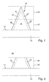
- a pyramidal structure 10 is selected here, which is to be produced on a surface 12 of a substrate 14 by means of a three-dimensional prototyping method.
- the data representing the structure 10 are decomposed by software technology into a jacket wall 16 and into a volume section 18 of the structure 10 lying within the jacket wall 16.
- the volume portion 18 is bounded on the one hand by the jacket wall 16 to the outside, on the other hand by the surface 12 of the substrate 14 is completed.
- structures 10 which are bounded in all directions by a jacket wall 16 and / or are not arranged on a substrate are also conceivable.
- the structure 10 is further subdivided into partial regions 20, 20 ', which adjoin one another directly and in particular cover the structure 10 completely and, for example, without overlapping.
- partial regions 20, 20 ' which adjoin one another directly and in particular cover the structure 10 completely and, for example, without overlapping.
- partial walls 22, 22' of the jacket wall 16 are included, such that when the partial areas 20, 20 'are assembled, the partial walls 22, 22' complete the complete jacket wall 16 (in particular without overlapping).
- the substrate 14 is arranged, for example, in a bath of a lithography material 24, which thus fills the space above the surface 12 of the substrate 14 (see. FIG. 2 ).
- the lithography material 24 is, for example, a liquid or viscous plastic paint which is both photopolymerizable and thermopolymerizable.
- the lithography material 24 can be polymerized controlled by energy input methods and thereby solidified.
- a first spatially spatially resolving energy input method is used, in which spatially spatially resolved polymerization can be induced in a focal region of a writing beam.
- a second energy input method for example, the thermopolymerization can take place, as explained in more detail below.
- the jacket wall 16 in the lithography material 24 is first polymerized and solidified with the spatially spatially resolving first energy input method (eg photopolymerization in a spatially displaceable focus area of a writing beam).
- first energy input method eg photopolymerization in a spatially displaceable focus area of a writing beam
- subregions 20, 20 ' are written successively.
- the write area 26 for the first, resolving energy input method is first laid onto the first subarea 20 of the structure 10 and the subwalls 22 of the first subarea 20 are written.
- the writing area 26 is laid over the further subarea 20 'of the structure 10 and the subwalls 22' are written, ie polymerized and solidified.
- a volume 28 of still unpolymerized lithographic material is enclosed by the jacket wall 16 and, in the illustrated example, also by the surface 12 of the substrate 14. This is due to the fact that the selected first energy application method for generating the jacket wall 16 has a high spatial resolution and controls only the jacket wall 16 polymerized.
- the enclosed volume 28 corresponds to the volume portion 18 of the structure 10.
- the jacket wall 16 can be formed in an intermediate development step surrounding lithography material are removed, for example, in a bath of developer medium.
- the thus exposed structure of casing wall 16 and trapped, not yet polymerized volume 28 of lithographic material can then be spent a device for generating a second energy input method.
- the second energy input method no longer needs to have a high spatial resolution. Rather, it is conceivable that the second energy input method acts globally on the entire structure enclosed by the jacket wall 16. For example, the substrate 14 with the jacket wall 16 and the enclosed volume 28 can be brought into a furnace for heating. By the energy input with the second energy input method then the trapped volume 28 is also polymerized and solidified.
- the characteristic of the curing of the volume 28 can be influenced and so a volume portion 18 are generated in the interior of the jacket 16, for example, the physical properties of the volume portion 18 deviate from the jacket wall 16.
- the second energy input method is designed such that after curing of the volume 28, a homogeneous structure 10 is formed, which is composed of the shell wall 16 and the enclosed therein volume portion 18, wherein the shell wall 16 and volume portion 18 same structural properties and / or physical properties.
- FIG. 5 again the preparation of the data representing the desired structure 10 is illustrated.
- the structure 10 is in turn disassembled into a jacket wall 16 and an enclosed volume portion 18.
- a support structure 30 lying within the jacket wall 16 is defined, which has a plurality of support elements 32.
- the support elements 32 extend between sections of the jacket wall 16 and the surface 12 of the substrate 14.
- support elements may additionally or alternatively be provided which extend exclusively between sections of the jacket wall. This is particularly suitable when the volume portion is enclosed only by casing walls 16, and no limitation of the volume portion 18 by the surface 12 of the substrate 14 takes place.
- the structure 10 can in turn be divided into a plurality of partial areas 20, 20 ', which in turn each comprise partial walls 22, 22', which are composed to form the jacket wall 16. Subsections 34, 34 'of the support structure 30 are then also contained in the subregions 20, 20', so that the entire support structure 30 is formed by assembling the subregions 20, 20 '.
- the substrate 14 is introduced into a bath of lithography material 24 by way of example.
- the writing area 26 is placed over the first portion 20 of the structure 10 and with the spatially resolving first energy input method, the partial walls 22 of the jacket wall 16 and the sections 34 of the support structure 30 polymerized.
- the write area 26 is laid over the further subarea 20 'of the structure 10 and the remaining subwalls and subsections of the support structure are written. As a result, a volume 28 of unpolymerized lithography material 24 is enclosed within the jacket wall 16 and possibly the surface 12 of the substrate 14.
- the unpolymerized volume 28 is penetrated by the solidified support elements 32 of the support structure 30. Since the support elements 32 in the example shown extend between portions of the jacket wall 16 and the substrate surface 12, prevent the support members 32 collapse of the jacket wall 16, for example, in a subsequent intermediate development step. In alternative embodiments, support members 32 extending between portions of the shell wall 16 may avoid deforming or floating away areas of the shell wall 16.
- the enclosed volume 28 is in turn polymerized with a second energy input method, which does not have to have precise spatial resolution.
- material may be previously removed in an intermediate development step.
- the volume 28 may have other physical and / or mechanical properties after polymerization than the support structure 30.
- the mechanical properties of the structure 10 can be adjusted.
- the second energy input method is selected such that in Inside the jacket wall creates a completely homogeneous structure.
- the structure 10 is in turn decomposed into a jacket wall 16 and a volume portion 18 enclosed thereby.
- the decomposition takes place in a plurality of subregions 20a, 20b, 20c, 20d, 20e, 20f, 20g.
- These subregions 20a to 20g each contain in turn sub-walls 22a, 22b,..., Of which, for reasons of clarity, only a few are provided with separate reference symbols by way of example.
- the subregions 20a to 20g contain support structures with support elements extending between sections of the jacket wall 16 and / or with support elements extending between sections of the jacket wall 16 and a substrate surface 12 (not shown).
- the subareas 20a to 20g are in turn written sequentially one after the other and the sub-walls 22 contained therein and possibly support elements or sections of the support structure are written.
- the sequence of execution of the subregions may in particular be such that a deformation or change in position of sections already written during the writing of a subsequent subarea is prevented.
- the partial regions 20a, 20b, 20c, 20d, 20e, 20f, 20g are preferably written in the order reproduced.
- the jacket wall 16 in the various subregions 20a to 20g has wall sections with different wall thicknesses.
- partial walls can be made thicker in subregions which must receive a greater load from the structure 10 (for example, the partial walls 22d and 22c in the subregions 20d and 20c).
Landscapes
- Engineering & Computer Science (AREA)
- Physics & Mathematics (AREA)
- Materials Engineering (AREA)
- Chemical & Material Sciences (AREA)
- Optics & Photonics (AREA)
- Manufacturing & Machinery (AREA)
- Mechanical Engineering (AREA)
- General Physics & Mathematics (AREA)
- Health & Medical Sciences (AREA)
- Toxicology (AREA)
- Microelectronics & Electronic Packaging (AREA)
- Electromagnetism (AREA)
- Oral & Maxillofacial Surgery (AREA)
- Thermal Sciences (AREA)
- Plasma & Fusion (AREA)
- Exposure And Positioning Against Photoresist Photosensitive Materials (AREA)
- Manufacturing Optical Record Carriers (AREA)
Applications Claiming Priority (1)
| Application Number | Priority Date | Filing Date | Title |
|---|---|---|---|
| DE102014221480.7A DE102014221480B4 (de) | 2014-10-22 | 2014-10-22 | Verfahren zum Herstellen einer dreidimensionalen Struktur |
Publications (3)
| Publication Number | Publication Date |
|---|---|
| EP3012688A1 true EP3012688A1 (fr) | 2016-04-27 |
| EP3012688B1 EP3012688B1 (fr) | 2019-10-02 |
| EP3012688B2 EP3012688B2 (fr) | 2023-02-08 |
Family
ID=53835320
Family Applications (1)
| Application Number | Title | Priority Date | Filing Date |
|---|---|---|---|
| EP15180364.0A Active EP3012688B2 (fr) | 2014-10-22 | 2015-08-10 | Procede de fabrication d'une structure tridimensionnelle |
Country Status (5)
| Country | Link |
|---|---|
| US (1) | US9937664B2 (fr) |
| EP (1) | EP3012688B2 (fr) |
| JP (1) | JP6560953B2 (fr) |
| CN (1) | CN105549328B (fr) |
| DE (1) | DE102014221480B4 (fr) |
Cited By (2)
| Publication number | Priority date | Publication date | Assignee | Title |
|---|---|---|---|---|
| EP3702132B1 (fr) | 2019-02-26 | 2023-01-11 | UpNano GmbH | Procédé de fabrication générative par lithographie de composants tridimensionnels |
| WO2023094133A1 (fr) * | 2021-11-25 | 2023-06-01 | Bayerische Motoren Werke Aktiengesellschaft | Méthode de fabrication additive d'un objet tridimensionnel |
Families Citing this family (11)
| Publication number | Priority date | Publication date | Assignee | Title |
|---|---|---|---|---|
| US10518429B2 (en) | 2015-06-30 | 2019-12-31 | The Gillette Company Llc | Polymeric cutting edge structures and method of manufacturing polymeric cutting edge structures |
| DE102015121748B4 (de) * | 2015-12-14 | 2025-09-11 | Concept Laser Gmbh | Strömungseinrichtung für eine Vorrichtung zur generativen Herstellung eines dreidimensionalen Objekts, Vorrichtung mit einer solchen Strömungseinrichtung und Verfahren zur Herstellung eines dreidimensionalen Objekts unter Verwendung einer Vorrichtung und einer entsprechenden Strömungseinrichtung |
| US10562200B2 (en) * | 2016-06-28 | 2020-02-18 | The Gillette Company Llc | Polymeric cutting edge structures and method of manufacturing polymeric cutting edge structures |
| US10780599B2 (en) | 2016-06-28 | 2020-09-22 | The Gillette Company Llc | Polymeric cutting edge structures and method of manufacturing polymeric cutting edge structures |
| DE102016014229A1 (de) | 2016-11-30 | 2018-05-30 | Giesecke+Devrient Currency Technology Gmbh | Herstellverfahren für Druckplatten für den Stichtiefdruck sowie Druckplatte für den Stichtiefdruck |
| US10413167B2 (en) | 2017-05-30 | 2019-09-17 | Synaptive Medical (Barbados) Inc. | Micro-optical surgical probes and micro-optical probe tips and methods of manufacture therefor |
| EP3698968A1 (fr) | 2019-02-22 | 2020-08-26 | Essilor International | Procédé et système de fabrication d'un élément de volume optique à partir d'un matériau durcissable à l'aide d'une technologie de fabrication additive |
| EP3756863A1 (fr) | 2019-06-24 | 2020-12-30 | Essilor International | Procédé et système de génération d'un fichier de fabrication pour la production d'un élément optique |
| WO2020260306A1 (fr) * | 2019-06-24 | 2020-12-30 | Essilor International | Procédé et machine de production d'un élément optique par fabrication additive |
| US11661468B2 (en) * | 2020-08-27 | 2023-05-30 | Align Technology, Inc. | Additive manufacturing using variable temperature-controlled resins |
| DE102023121854A1 (de) | 2023-08-16 | 2025-02-20 | Xolo Gmbh | Verfahren zur Herstellung eines dreidimensionalen Objekts |
Citations (2)
| Publication number | Priority date | Publication date | Assignee | Title |
|---|---|---|---|---|
| US4575330A (en) | 1984-08-08 | 1986-03-11 | Uvp, Inc. | Apparatus for production of three-dimensional objects by stereolithography |
| DE19507881B4 (de) | 1994-03-10 | 2006-11-23 | Materialise N.V. | Verfahren zum Stützen eines Objekts, verfertigt durch Stereolithographie oder ein anderes schnelles Prototypen-Fertigungsverfahren |
Family Cites Families (5)
| Publication number | Priority date | Publication date | Assignee | Title |
|---|---|---|---|---|
| US5198159A (en) | 1990-10-09 | 1993-03-30 | Matsushita Electric Works, Ltd. | Process of fabricating three-dimensional objects from a light curable resin liquid |
| JP2795126B2 (ja) * | 1993-04-16 | 1998-09-10 | 株式会社デンソー | 曲面加工方法及びその装置 |
| US6364986B1 (en) * | 1999-10-04 | 2002-04-02 | The United States Of America As Represented By The Secretary Of The Navy | High-strength parts formed using stereolithography |
| US6730256B1 (en) * | 2000-08-04 | 2004-05-04 | Massachusetts Institute Of Technology | Stereolithographic patterning with interlayer surface modifications |
| KR20060038988A (ko) * | 2003-07-11 | 2006-05-04 | 코닌클리케 필립스 일렉트로닉스 엔.브이. | 광학 표면 제조를 위한 몰드 제조 방법, 컨택트 렌즈 제조방법 및 이러한 방법들에 사용되는 디바이스 |
-
2014
- 2014-10-22 DE DE102014221480.7A patent/DE102014221480B4/de not_active Revoked
-
2015
- 2015-08-10 EP EP15180364.0A patent/EP3012688B2/fr active Active
- 2015-09-29 US US14/869,377 patent/US9937664B2/en active Active
- 2015-10-14 CN CN201510664550.8A patent/CN105549328B/zh active Active
- 2015-10-16 JP JP2015204644A patent/JP6560953B2/ja active Active
Patent Citations (3)
| Publication number | Priority date | Publication date | Assignee | Title |
|---|---|---|---|---|
| US4575330A (en) | 1984-08-08 | 1986-03-11 | Uvp, Inc. | Apparatus for production of three-dimensional objects by stereolithography |
| US4575330B1 (fr) | 1984-08-08 | 1989-12-19 | ||
| DE19507881B4 (de) | 1994-03-10 | 2006-11-23 | Materialise N.V. | Verfahren zum Stützen eines Objekts, verfertigt durch Stereolithographie oder ein anderes schnelles Prototypen-Fertigungsverfahren |
Non-Patent Citations (3)
| Title |
|---|
| MA W ET AL: "NURBS-based adaptive slicing for efficient rapid prototyping", COMPUTER AIDED DESIGN, ELSEVIER PUBLISHERS BV., BARKING, GB, vol. 36, no. 13, 1 November 2004 (2004-11-01), pages 1309 - 1325, XP004534034, ISSN: 0010-4485, DOI: 10.1016/J.CAD.2004.02.001 * |
| MANGIRDAS MALINAUSKAS ET AL: "<title>Femtosecond laser fabrication of hybrid micro-optical elements and their integration on the fiber tip</title>", PROCEEDINGS OF SPIE, vol. 7716, 30 April 2010 (2010-04-30), US, pages 77160A, XP055241951, ISSN: 0277-786X, ISBN: 978-1-62841-730-2, DOI: 10.1117/12.854396 * |
| ROSA L ET AL: "Optoplasmonics: hybridization in 3D", PROCEEDINGS OF SPIE, S P I E - INTERNATIONAL SOCIETY FOR OPTICAL ENGINEERING, US, vol. 8923, 7 December 2013 (2013-12-07), pages 89231Q - 89231Q, XP060031915, ISSN: 0277-786X, ISBN: 978-1-62841-730-2, DOI: 10.1117/12.2033716 * |
Cited By (2)
| Publication number | Priority date | Publication date | Assignee | Title |
|---|---|---|---|---|
| EP3702132B1 (fr) | 2019-02-26 | 2023-01-11 | UpNano GmbH | Procédé de fabrication générative par lithographie de composants tridimensionnels |
| WO2023094133A1 (fr) * | 2021-11-25 | 2023-06-01 | Bayerische Motoren Werke Aktiengesellschaft | Méthode de fabrication additive d'un objet tridimensionnel |
Also Published As
| Publication number | Publication date |
|---|---|
| CN105549328A (zh) | 2016-05-04 |
| JP6560953B2 (ja) | 2019-08-14 |
| JP2016083933A (ja) | 2016-05-19 |
| US9937664B2 (en) | 2018-04-10 |
| US20160114530A1 (en) | 2016-04-28 |
| EP3012688B1 (fr) | 2019-10-02 |
| EP3012688B2 (fr) | 2023-02-08 |
| DE102014221480A1 (de) | 2016-04-28 |
| DE102014221480B4 (de) | 2017-10-05 |
| CN105549328B (zh) | 2018-04-13 |
Similar Documents
| Publication | Publication Date | Title |
|---|---|---|
| EP3012688B1 (fr) | Procédé de fabrication d'une structure tridimensionnelle | |
| DE3587656T2 (de) | Stereolithographische Vorrichtung und Verfahren zur Herstellung von dreidimensionalen Gegenständen. | |
| EP3621766B1 (fr) | Procédé de génératipon d'une structure 3d par lithographie au laser à l'aide d'une dose d'éclairage modifiée aux sections de bord, ainsi que produit-programme informatique correspondant | |
| EP3174689B1 (fr) | Composant micromécanique et procédé de fabrication | |
| EP3093123B1 (fr) | Procédé de fabrication d'une structure tridimensionnelle | |
| DE102009058262A1 (de) | Geschichtete Strahlensensitive Materialien mit variierender Sensitivität | |
| DE102016209933A1 (de) | Vorrichtung und Verfahren zum generativen Herstellen eines dreidimensionalen Objekts | |
| DE102015207158A1 (de) | Verfahren und Vorrichtung zum Herstellen eines dreidimensionalen Objekts | |
| DE102009000642A1 (de) | Verfahren zur Herstellung mikrostrukturierter Bauteile mittels Photolithographie | |
| DE102014007562A1 (de) | Vorrichtung und Verfahren zur Herstellung von dreidimensionalen Formteilen mit integrierter Leiterbildstruktur durch Additive Manufacturing | |
| DE102015225300A1 (de) | Verfahren und Anordnungen zur Verringerung der Grenzflächenadhäsion bei der Photopolymerisation | |
| EP3802059B1 (fr) | Procédé de fabrication d'un arctile moule | |
| DE102014111559B4 (de) | Verfahren zur Herstellung von Schichtenfolgen und Formkörpern aus einer Anzahl von Schichten | |
| KR101965261B1 (ko) | 이광자 스테레오리소그라피에 의한 3차원 메쉬형 미세구조체 제조방법 | |
| DE102020132417B4 (de) | Verfahren und Vorrichtung zur Herstellung von mikroskopischen dreidimensionalen Multimaterialstrukturen | |
| DE102012109130B4 (de) | Verfahren und Vorrichtungen zur Herstellung dreidimensionaler Strukturen | |
| DE202014010855U1 (de) | Digitales Codieren von Gummiartikeln | |
| DE102009054024A1 (de) | Elektronisch ansteuerbare Matrix-Maske | |
| EP0551119A1 (fr) | Procédé de fabrication d'éléments microoptiques non-linéaires | |
| DE102023134117A1 (de) | Verfahren zur Herstellung einer Mikrooptik | |
| WO2022074044A1 (fr) | Procédé de production d'un composant et composant | |
| WO2019124150A1 (fr) | Procédé de fabrication additive | |
| DE10200313A1 (de) | Verfahren und Vorrichtung zur Herstellung von dreidimensionalen keramischen Strukturen | |
| WO2015188909A1 (fr) | Procédé de production d'un outil d'estampage par lithographie 3d |
Legal Events
| Date | Code | Title | Description |
|---|---|---|---|
| PUAI | Public reference made under article 153(3) epc to a published international application that has entered the european phase |
Free format text: ORIGINAL CODE: 0009012 |
|
| AK | Designated contracting states |
Kind code of ref document: A1 Designated state(s): AL AT BE BG CH CY CZ DE DK EE ES FI FR GB GR HR HU IE IS IT LI LT LU LV MC MK MT NL NO PL PT RO RS SE SI SK SM TR |
|
| AX | Request for extension of the european patent |
Extension state: BA ME |
|
| 17P | Request for examination filed |
Effective date: 20161025 |
|
| RBV | Designated contracting states (corrected) |
Designated state(s): AL AT BE BG CH CY CZ DE DK EE ES FI FR GB GR HR HU IE IS IT LI LT LU LV MC MK MT NL NO PL PT RO RS SE SI SK SM TR |
|
| STAA | Information on the status of an ep patent application or granted ep patent |
Free format text: STATUS: EXAMINATION IS IN PROGRESS |
|
| 17Q | First examination report despatched |
Effective date: 20170811 |
|
| RIC1 | Information provided on ipc code assigned before grant |
Ipc: B29C 64/282 20170101ALI20181221BHEP Ipc: B29C 64/124 20170101ALI20181221BHEP Ipc: B29L 29/00 20060101ALI20181221BHEP Ipc: G03F 7/09 20060101AFI20181221BHEP Ipc: B29C 64/40 20170101ALI20181221BHEP Ipc: B29C 64/135 20170101ALI20181221BHEP Ipc: B29C 64/295 20170101ALI20181221BHEP Ipc: G03F 7/20 20060101ALI20181221BHEP Ipc: B29C 33/38 20060101ALI20181221BHEP Ipc: B29C 64/141 20170101ALI20181221BHEP Ipc: B29C 64/10 20170101ALI20181221BHEP Ipc: B29K 105/00 20060101ALI20181221BHEP Ipc: B29C 64/129 20170101ALI20181221BHEP Ipc: B29L 9/00 20060101ALI20181221BHEP Ipc: G03F 7/00 20060101ALI20181221BHEP Ipc: B29C 35/08 20060101ALI20181221BHEP Ipc: B29C 64/277 20170101ALI20181221BHEP Ipc: B29C 64/153 20170101ALI20181221BHEP Ipc: G03F 7/11 20060101ALI20181221BHEP |
|
| GRAP | Despatch of communication of intention to grant a patent |
Free format text: ORIGINAL CODE: EPIDOSNIGR1 |
|
| STAA | Information on the status of an ep patent application or granted ep patent |
Free format text: STATUS: GRANT OF PATENT IS INTENDED |
|
| INTG | Intention to grant announced |
Effective date: 20190307 |
|
| RIN1 | Information on inventor provided before grant (corrected) |
Inventor name: REINER, ROMAN REINHARD Inventor name: TANGUY, YANN Inventor name: NIESLER, FABIAN Inventor name: THIEL, MICHAEL |
|
| GRAS | Grant fee paid |
Free format text: ORIGINAL CODE: EPIDOSNIGR3 |
|
| GRAA | (expected) grant |
Free format text: ORIGINAL CODE: 0009210 |
|
| STAA | Information on the status of an ep patent application or granted ep patent |
Free format text: STATUS: THE PATENT HAS BEEN GRANTED |
|
| AK | Designated contracting states |
Kind code of ref document: B1 Designated state(s): AL AT BE BG CH CY CZ DE DK EE ES FI FR GB GR HR HU IE IS IT LI LT LU LV MC MK MT NL NO PL PT RO RS SE SI SK SM TR |
|
| REG | Reference to a national code |
Ref country code: GB Ref legal event code: FG4D Free format text: NOT ENGLISH |
|
| REG | Reference to a national code |
Ref country code: CH Ref legal event code: EP Ref country code: AT Ref legal event code: REF Ref document number: 1186861 Country of ref document: AT Kind code of ref document: T Effective date: 20191015 |
|
| REG | Reference to a national code |
Ref country code: DE Ref legal event code: R096 Ref document number: 502015010500 Country of ref document: DE |
|
| REG | Reference to a national code |
Ref country code: IE Ref legal event code: FG4D Free format text: LANGUAGE OF EP DOCUMENT: GERMAN |
|
| REG | Reference to a national code |
Ref country code: CH Ref legal event code: NV Representative=s name: DREISS PATENTANWAELTE PARTG MBB, DE |
|
| REG | Reference to a national code |
Ref country code: NL Ref legal event code: MP Effective date: 20191002 |
|
| REG | Reference to a national code |
Ref country code: LT Ref legal event code: MG4D |
|
| PG25 | Lapsed in a contracting state [announced via postgrant information from national office to epo] |
Ref country code: LV Free format text: LAPSE BECAUSE OF FAILURE TO SUBMIT A TRANSLATION OF THE DESCRIPTION OR TO PAY THE FEE WITHIN THE PRESCRIBED TIME-LIMIT Effective date: 20191002 Ref country code: NL Free format text: LAPSE BECAUSE OF FAILURE TO SUBMIT A TRANSLATION OF THE DESCRIPTION OR TO PAY THE FEE WITHIN THE PRESCRIBED TIME-LIMIT Effective date: 20191002 Ref country code: PL Free format text: LAPSE BECAUSE OF FAILURE TO SUBMIT A TRANSLATION OF THE DESCRIPTION OR TO PAY THE FEE WITHIN THE PRESCRIBED TIME-LIMIT Effective date: 20191002 Ref country code: ES Free format text: LAPSE BECAUSE OF FAILURE TO SUBMIT A TRANSLATION OF THE DESCRIPTION OR TO PAY THE FEE WITHIN THE PRESCRIBED TIME-LIMIT Effective date: 20191002 Ref country code: LT Free format text: LAPSE BECAUSE OF FAILURE TO SUBMIT A TRANSLATION OF THE DESCRIPTION OR TO PAY THE FEE WITHIN THE PRESCRIBED TIME-LIMIT Effective date: 20191002 Ref country code: NO Free format text: LAPSE BECAUSE OF FAILURE TO SUBMIT A TRANSLATION OF THE DESCRIPTION OR TO PAY THE FEE WITHIN THE PRESCRIBED TIME-LIMIT Effective date: 20200102 Ref country code: GR Free format text: LAPSE BECAUSE OF FAILURE TO SUBMIT A TRANSLATION OF THE DESCRIPTION OR TO PAY THE FEE WITHIN THE PRESCRIBED TIME-LIMIT Effective date: 20200103 Ref country code: BG Free format text: LAPSE BECAUSE OF FAILURE TO SUBMIT A TRANSLATION OF THE DESCRIPTION OR TO PAY THE FEE WITHIN THE PRESCRIBED TIME-LIMIT Effective date: 20200102 Ref country code: SE Free format text: LAPSE BECAUSE OF FAILURE TO SUBMIT A TRANSLATION OF THE DESCRIPTION OR TO PAY THE FEE WITHIN THE PRESCRIBED TIME-LIMIT Effective date: 20191002 Ref country code: FI Free format text: LAPSE BECAUSE OF FAILURE TO SUBMIT A TRANSLATION OF THE DESCRIPTION OR TO PAY THE FEE WITHIN THE PRESCRIBED TIME-LIMIT Effective date: 20191002 Ref country code: PT Free format text: LAPSE BECAUSE OF FAILURE TO SUBMIT A TRANSLATION OF THE DESCRIPTION OR TO PAY THE FEE WITHIN THE PRESCRIBED TIME-LIMIT Effective date: 20200203 |
|
| PG25 | Lapsed in a contracting state [announced via postgrant information from national office to epo] |
Ref country code: RS Free format text: LAPSE BECAUSE OF FAILURE TO SUBMIT A TRANSLATION OF THE DESCRIPTION OR TO PAY THE FEE WITHIN THE PRESCRIBED TIME-LIMIT Effective date: 20191002 Ref country code: IS Free format text: LAPSE BECAUSE OF FAILURE TO SUBMIT A TRANSLATION OF THE DESCRIPTION OR TO PAY THE FEE WITHIN THE PRESCRIBED TIME-LIMIT Effective date: 20200224 Ref country code: CZ Free format text: LAPSE BECAUSE OF FAILURE TO SUBMIT A TRANSLATION OF THE DESCRIPTION OR TO PAY THE FEE WITHIN THE PRESCRIBED TIME-LIMIT Effective date: 20191002 Ref country code: HR Free format text: LAPSE BECAUSE OF FAILURE TO SUBMIT A TRANSLATION OF THE DESCRIPTION OR TO PAY THE FEE WITHIN THE PRESCRIBED TIME-LIMIT Effective date: 20191002 |
|
| PG25 | Lapsed in a contracting state [announced via postgrant information from national office to epo] |
Ref country code: AL Free format text: LAPSE BECAUSE OF FAILURE TO SUBMIT A TRANSLATION OF THE DESCRIPTION OR TO PAY THE FEE WITHIN THE PRESCRIBED TIME-LIMIT Effective date: 20191002 |
|
| REG | Reference to a national code |
Ref country code: DE Ref legal event code: R026 Ref document number: 502015010500 Country of ref document: DE |
|
| PLBI | Opposition filed |
Free format text: ORIGINAL CODE: 0009260 |
|
| PLAX | Notice of opposition and request to file observation + time limit sent |
Free format text: ORIGINAL CODE: EPIDOSNOBS2 |
|
| PG2D | Information on lapse in contracting state deleted |
Ref country code: IS |
|
| PG25 | Lapsed in a contracting state [announced via postgrant information from national office to epo] |
Ref country code: EE Free format text: LAPSE BECAUSE OF FAILURE TO SUBMIT A TRANSLATION OF THE DESCRIPTION OR TO PAY THE FEE WITHIN THE PRESCRIBED TIME-LIMIT Effective date: 20191002 Ref country code: DK Free format text: LAPSE BECAUSE OF FAILURE TO SUBMIT A TRANSLATION OF THE DESCRIPTION OR TO PAY THE FEE WITHIN THE PRESCRIBED TIME-LIMIT Effective date: 20191002 Ref country code: RO Free format text: LAPSE BECAUSE OF FAILURE TO SUBMIT A TRANSLATION OF THE DESCRIPTION OR TO PAY THE FEE WITHIN THE PRESCRIBED TIME-LIMIT Effective date: 20191002 Ref country code: IS Free format text: LAPSE BECAUSE OF FAILURE TO SUBMIT A TRANSLATION OF THE DESCRIPTION OR TO PAY THE FEE WITHIN THE PRESCRIBED TIME-LIMIT Effective date: 20200202 |
|
| 26 | Opposition filed |
Opponent name: MULTIPHOTON OPTICS GMBH Effective date: 20200702 |
|
| PG25 | Lapsed in a contracting state [announced via postgrant information from national office to epo] |
Ref country code: SM Free format text: LAPSE BECAUSE OF FAILURE TO SUBMIT A TRANSLATION OF THE DESCRIPTION OR TO PAY THE FEE WITHIN THE PRESCRIBED TIME-LIMIT Effective date: 20191002 Ref country code: IT Free format text: LAPSE BECAUSE OF FAILURE TO SUBMIT A TRANSLATION OF THE DESCRIPTION OR TO PAY THE FEE WITHIN THE PRESCRIBED TIME-LIMIT Effective date: 20191002 Ref country code: SK Free format text: LAPSE BECAUSE OF FAILURE TO SUBMIT A TRANSLATION OF THE DESCRIPTION OR TO PAY THE FEE WITHIN THE PRESCRIBED TIME-LIMIT Effective date: 20191002 |
|
| PLBB | Reply of patent proprietor to notice(s) of opposition received |
Free format text: ORIGINAL CODE: EPIDOSNOBS3 |
|
| PG25 | Lapsed in a contracting state [announced via postgrant information from national office to epo] |
Ref country code: SI Free format text: LAPSE BECAUSE OF FAILURE TO SUBMIT A TRANSLATION OF THE DESCRIPTION OR TO PAY THE FEE WITHIN THE PRESCRIBED TIME-LIMIT Effective date: 20191002 |
|
| REG | Reference to a national code |
Ref country code: DE Ref legal event code: R082 Ref document number: 502015010500 Country of ref document: DE Representative=s name: DREISS PATENTANWAELTE PARTG MBB, DE Ref country code: DE Ref legal event code: R081 Ref document number: 502015010500 Country of ref document: DE Owner name: NANOSCRIBE HOLDING GMBH, DE Free format text: FORMER OWNER: NANOSCRIBE GMBH, 76344 EGGENSTEIN-LEOPOLDSHAFEN, DE |
|
| PG25 | Lapsed in a contracting state [announced via postgrant information from national office to epo] |
Ref country code: MC Free format text: LAPSE BECAUSE OF FAILURE TO SUBMIT A TRANSLATION OF THE DESCRIPTION OR TO PAY THE FEE WITHIN THE PRESCRIBED TIME-LIMIT Effective date: 20191002 |
|
| PG25 | Lapsed in a contracting state [announced via postgrant information from national office to epo] |
Ref country code: LU Free format text: LAPSE BECAUSE OF NON-PAYMENT OF DUE FEES Effective date: 20200810 |
|
| REG | Reference to a national code |
Ref country code: BE Ref legal event code: MM Effective date: 20200831 |
|
| PG25 | Lapsed in a contracting state [announced via postgrant information from national office to epo] |
Ref country code: BE Free format text: LAPSE BECAUSE OF NON-PAYMENT OF DUE FEES Effective date: 20200831 Ref country code: IE Free format text: LAPSE BECAUSE OF NON-PAYMENT OF DUE FEES Effective date: 20200810 |
|
| REG | Reference to a national code |
Ref country code: AT Ref legal event code: MM01 Ref document number: 1186861 Country of ref document: AT Kind code of ref document: T Effective date: 20200810 |
|
| PG25 | Lapsed in a contracting state [announced via postgrant information from national office to epo] |
Ref country code: AT Free format text: LAPSE BECAUSE OF NON-PAYMENT OF DUE FEES Effective date: 20200810 |
|
| PLBP | Opposition withdrawn |
Free format text: ORIGINAL CODE: 0009264 |
|
| PLAY | Examination report in opposition despatched + time limit |
Free format text: ORIGINAL CODE: EPIDOSNORE2 |
|
| PLBC | Reply to examination report in opposition received |
Free format text: ORIGINAL CODE: EPIDOSNORE3 |
|
| PG25 | Lapsed in a contracting state [announced via postgrant information from national office to epo] |
Ref country code: TR Free format text: LAPSE BECAUSE OF FAILURE TO SUBMIT A TRANSLATION OF THE DESCRIPTION OR TO PAY THE FEE WITHIN THE PRESCRIBED TIME-LIMIT Effective date: 20191002 Ref country code: MT Free format text: LAPSE BECAUSE OF FAILURE TO SUBMIT A TRANSLATION OF THE DESCRIPTION OR TO PAY THE FEE WITHIN THE PRESCRIBED TIME-LIMIT Effective date: 20191002 Ref country code: CY Free format text: LAPSE BECAUSE OF FAILURE TO SUBMIT A TRANSLATION OF THE DESCRIPTION OR TO PAY THE FEE WITHIN THE PRESCRIBED TIME-LIMIT Effective date: 20191002 |
|
| PG25 | Lapsed in a contracting state [announced via postgrant information from national office to epo] |
Ref country code: MK Free format text: LAPSE BECAUSE OF FAILURE TO SUBMIT A TRANSLATION OF THE DESCRIPTION OR TO PAY THE FEE WITHIN THE PRESCRIBED TIME-LIMIT Effective date: 20191002 |
|
| PUAH | Patent maintained in amended form |
Free format text: ORIGINAL CODE: 0009272 |
|
| STAA | Information on the status of an ep patent application or granted ep patent |
Free format text: STATUS: PATENT MAINTAINED AS AMENDED |
|
| 27A | Patent maintained in amended form |
Effective date: 20230208 |
|
| AK | Designated contracting states |
Kind code of ref document: B2 Designated state(s): AL AT BE BG CH CY CZ DE DK EE ES FI FR GB GR HR HU IE IS IT LI LT LU LV MC MK MT NL NO PL PT RO RS SE SI SK SM TR |
|
| REG | Reference to a national code |
Ref country code: DE Ref legal event code: R102 Ref document number: 502015010500 Country of ref document: DE |
|
| P01 | Opt-out of the competence of the unified patent court (upc) registered |
Effective date: 20230504 |
|
| PGFP | Annual fee paid to national office [announced via postgrant information from national office to epo] |
Ref country code: DE Payment date: 20250819 Year of fee payment: 11 |
|
| PGFP | Annual fee paid to national office [announced via postgrant information from national office to epo] |
Ref country code: GB Payment date: 20250822 Year of fee payment: 11 |
|
| PGFP | Annual fee paid to national office [announced via postgrant information from national office to epo] |
Ref country code: FR Payment date: 20250821 Year of fee payment: 11 |
|
| PGFP | Annual fee paid to national office [announced via postgrant information from national office to epo] |
Ref country code: CH Payment date: 20250901 Year of fee payment: 11 |