EP3018364B1 - Dispositif de commande avec piston coulissant - Google Patents
Dispositif de commande avec piston coulissant Download PDFInfo
- Publication number
- EP3018364B1 EP3018364B1 EP14192441.5A EP14192441A EP3018364B1 EP 3018364 B1 EP3018364 B1 EP 3018364B1 EP 14192441 A EP14192441 A EP 14192441A EP 3018364 B1 EP3018364 B1 EP 3018364B1
- Authority
- EP
- European Patent Office
- Prior art keywords
- secondary pressure
- connections
- threshold value
- pair
- valve
- Prior art date
- Legal status (The legal status is an assumption and is not a legal conclusion. Google has not performed a legal analysis and makes no representation as to the accuracy of the status listed.)
- Active
Links
Images


Classifications
-
- F—MECHANICAL ENGINEERING; LIGHTING; HEATING; WEAPONS; BLASTING
- F15—FLUID-PRESSURE ACTUATORS; HYDRAULICS OR PNEUMATICS IN GENERAL
- F15B—SYSTEMS ACTING BY MEANS OF FLUIDS IN GENERAL; FLUID-PRESSURE ACTUATORS, e.g. SERVOMOTORS; DETAILS OF FLUID-PRESSURE SYSTEMS, NOT OTHERWISE PROVIDED FOR
- F15B11/00—Servomotor systems without provision for follow-up action; Circuits therefor
- F15B11/02—Systems essentially incorporating special features for controlling the speed or actuating force of an output member
- F15B11/04—Systems essentially incorporating special features for controlling the speed or actuating force of an output member for controlling the speed
- F15B11/05—Systems essentially incorporating special features for controlling the speed or actuating force of an output member for controlling the speed specially adapted to maintain constant speed, e.g. pressure-compensated, load-responsive
-
- F—MECHANICAL ENGINEERING; LIGHTING; HEATING; WEAPONS; BLASTING
- F15—FLUID-PRESSURE ACTUATORS; HYDRAULICS OR PNEUMATICS IN GENERAL
- F15B—SYSTEMS ACTING BY MEANS OF FLUIDS IN GENERAL; FLUID-PRESSURE ACTUATORS, e.g. SERVOMOTORS; DETAILS OF FLUID-PRESSURE SYSTEMS, NOT OTHERWISE PROVIDED FOR
- F15B13/00—Details of servomotor systems ; Valves for servomotor systems
- F15B13/02—Fluid distribution or supply devices characterised by their adaptation to the control of servomotors
- F15B13/04—Fluid distribution or supply devices characterised by their adaptation to the control of servomotors for use with a single servomotor
- F15B13/0416—Fluid distribution or supply devices characterised by their adaptation to the control of servomotors for use with a single servomotor with means or adapted for load sensing
- F15B13/0417—Load sensing elements; Internal fluid connections therefor; Anti-saturation or pressure-compensation valves
-
- F—MECHANICAL ENGINEERING; LIGHTING; HEATING; WEAPONS; BLASTING
- F15—FLUID-PRESSURE ACTUATORS; HYDRAULICS OR PNEUMATICS IN GENERAL
- F15B—SYSTEMS ACTING BY MEANS OF FLUIDS IN GENERAL; FLUID-PRESSURE ACTUATORS, e.g. SERVOMOTORS; DETAILS OF FLUID-PRESSURE SYSTEMS, NOT OTHERWISE PROVIDED FOR
- F15B2211/00—Circuits for servomotor systems
- F15B2211/60—Circuit components or control therefor
- F15B2211/605—Load sensing circuits
- F15B2211/6051—Load sensing circuits having valve means between output member and the load sensing circuit
- F15B2211/6055—Load sensing circuits having valve means between output member and the load sensing circuit using pressure relief valves
-
- F—MECHANICAL ENGINEERING; LIGHTING; HEATING; WEAPONS; BLASTING
- F15—FLUID-PRESSURE ACTUATORS; HYDRAULICS OR PNEUMATICS IN GENERAL
- F15B—SYSTEMS ACTING BY MEANS OF FLUIDS IN GENERAL; FLUID-PRESSURE ACTUATORS, e.g. SERVOMOTORS; DETAILS OF FLUID-PRESSURE SYSTEMS, NOT OTHERWISE PROVIDED FOR
- F15B2211/00—Circuits for servomotor systems
- F15B2211/60—Circuit components or control therefor
- F15B2211/65—Methods of control of the load sensing pressure
- F15B2211/654—Methods of control of the load sensing pressure the load sensing pressure being lower than the load pressure
Definitions
- the invention relates to a control device according to the preamble of patent claim 1.
- EP 2 157 320 A1 known control device is set to a pressure-responsive responsive secondary pressure relief valve in the load pressure signal circuit value of the secondary pressure within the same Auslenkhubs the spool from the center position by means of a parallel proportional seat valve disposed in a line leading from the load pressure signal to the tank and actuated by a proportional solenoid.
- This proportional seat valve requires considerable circuitry, line technology and control technology overhead and to control either the sampling of Auslenkhubs the spool and / or the pressure conditions in the hydraulic consumer.
- the forest crane has a gripper operated by a hydraulic consumer, with which the gripped tree trunks are held, and further hydraulic consumers for moving the gripper. Since the gripper usually no load-holding valves are installed because of unnecessary costs and deteriorated dynamics of the tree trunks holding gripper would slowly open in the middle position of the gripper-proportional directional spool, since the spool only slider-tight and leakage to the tank occurs. For this reason, for loading or stowing the gripped tree trunks, the motion control is used with the same active gripping function.
- the crane operator does not press the pedal for the gripping function, provided that the tree trunks are not too heavy, only to reliably hold tree trunks in the gripper.
- the crane operator makes this intuitively as he moves gripped tree trunks.
- the pedal deflection so the deflection of the piston valve from the center position, no longer matters, but there is the constant limit for the maximum force required in this deflection gripping force, as long as the gripper holds the logs pressed together, although a lower gripping force would be sufficient.
- so actuated gripping function of the load pressure signal circuit operates as a constant pressure system, whereby hydraulic energy is destroyed. Similar, hydraulic energy-destroying operating situations are also found in hydraulic excavators or similar hydraulic implements.
- the invention has for its object to provide a control device of the type mentioned, with the, e.g. For such in practice more frequently occurring operating situations unnecessary hydraulic energy losses can be minimized.
- the stated object is solved with the features of claim 1.
- a lower limit is set and in another part of the Auslenkhubs a higher limit, each from the load pressure in the load pressure signal circuit as a so-called secondary pressure
- a favorable energy loss and Kolbenschieber- hubtouche e.g. realized two-stage, secondary pressure limiting in the same direction of deflection, is saved by the hydraulic energy when the higher limit is not necessary.
- the change of the limit may be in stages or even proportionally according to an appropriate law.
- the limit is changed by disconnecting a secondary pressure relief valve from the load pressure signal circuit, i.
- the secondary pressure relief valve sets in a certain part of Auslenkhubs a low limit before within the same Auslenkhubs after disconnecting the secondary pressure relief valve from the load pressure signal circuit, the load pressure further to a higher limit and thus, for example via a feed regulator, the operating pressure of the hydraulic consumer increases, for example until the response of a main system pressure relief valve.
- the spool itself allows the limit value to be changed within the same Auslenkhubs because the second or first bypass structure initially a single secondary pressure relief valve can be effective and this is dependent on the load pressure signal circuit or the load pressure signal, or at two for the two Auslenkiquesen the spool provided secondary pressure relief valves for different limits simultaneously with the first bypass structure both secondary pressure relief valves can be acted upon by the load pressure signal and stroke dependent only the secondary pressure relief valve set to the higher limit.
- two differently preset secondary pressure relief valves e.g. for the Auslenkhübe from the center position in both directions, provided, wherein the change of the limit within the same Auslenkhubs by switching from a secondary pressure relief valve to the other or by applying both, depending on the Auslenkhub the spool.
- a first connection pair preferably a recess pair
- a second Connection is connected to the load pressure signal circuit, preferably via a throttle.
- a first, the first pair of terminals for mutual connection overrunning bridging structure is provided, preferably a group of bridging recesses.
- a second pair of connections preferably a recess pair, provided axially offset from the first terminal pair, of which a terminal is connected to the other secondary pressure relief valve and the other terminal is connected to the load pressure signal circuit, preferably via a throttle.
- a second bridging structure preferably a group of indentations, is provided axially offset from the first bridging structure, which pass over the terminals of the second connection pair so that, depending on the deflection stroke, the load pressure signal circuit is connected to a secondary pressure limiting valve is, while the other secondary pressure relief valve is separated from the load pressure signal circuit, and in another part of the same Auslenkhubs the load pressure signal circuit with the other secondary pressure relief valve or both is connected simultaneously.
- the set to the low limit secondary pressure relief valve is separated from the load pressure signal circuit or insulated from the fed load pressure signal so that only the set to the higher limit secondary pressure relief valve responds.
- a plurality of differently set secondary pressure limiting valves and correspondingly many bridging structures could be provided.
- connection of each connection pair is connected to a control side of a supply regulator pressure compensator arranged in a pump line to a pump connection of the proportional directional valve.
- the inlet regulator pressure compensator keeps constant the pressure difference set by the position within the deflection stroke via the spool, depending on the respective limit value.
- the higher limit value acts in an end part of the Auslenkhubs of the spool from the center position, and previously the low limit, so that the hydraulic consumer is acted upon only at the end portion of the Auslenkhubs at full pressure.
- the higher limit in an initial part and an end part of the Auslenkhubs acts from the center position, and the low limit acts in an intermediate part between the initial part and the end part of the Auslenkhubs.
- a deflection direction from the center position continuously acts either the higher or the lower limit.
- this can be the deflection stroke, via which the gripper is relieved and / or opened.
- the low limit value is set by a secondary pressure limiting valve
- the higher limit value is set either at a further secondary pressure limiting valve or corresponds to a pressure in the load pressure signal circuit which is not set by any secondary pressure limiting valve.
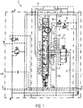
- Fig. 1 illustrates a control device S for a hydraulic consumer H, for example, a forest crane or excavator, in the non-actuated state, optionally not shown further control devices can be linked to the control device S shown, for example, for further hydraulic consumers.
- a hydraulic consumer H for example, a forest crane or excavator
- the control device S comprises a proportional directional spool 1 (4/3-proportional directional spool in the illustrated embodiment, as a non-limiting example) operable by two proportional solenoids and pressure pilot controls, and containing a spool R in a bore V.
- a proportional directional spool 1 (4/3-proportional directional spool in the illustrated embodiment, as a non-limiting example) operable by two proportional solenoids and pressure pilot controls, and containing a spool R in a bore V.
- the proportional directional spool valve 1 in the embodiment shown as secondary pressure relief K two secondary pressure relief valves 2, 3 associated with the secondary pressure relief valve 2 for the Auslenkhub for applying the power A to a higher limit P1 ( Fig. 6 to 8 ) is set, however, the secondary pressure relief valve 3 for the opposite Auslenkhub (working line B) to a low limit P2 ( Fig. 6 to 8 ).
- the spool R is from the center position shown in a switching position a (act on the working line A, relieve the working line B to a tank line T) adjustable.
- a switching position set (working line A to tank line T relieved, working line B applied), in the FIG. 1 is divided into two parts b ', b, although it is the same switching position.
- a feed regulator pressure compensator 4 is provided in a pump line P.
- the inlet regulator pressure compensator 4 is acted upon on the control side by a spring and a control line 27, and at the closing control side via a control line which branches off from the output side of the inlet regulator pressure compensator 4.
- only a single secondary pressure relief valve 2 or 3 could be provided, or could be provided for each or a deflection several different set secondary pressure relief valves.
- connection 7 of the working line B is arranged centrally and adjacent thereto a connection 8 of the working line A.
- connection 9 is used, whereas for tapping the load pressure in the working line A a connection 10 is located adjacent to this Connection 11 to the tank line T.
- connections are provided, namely a terminal 12 which is connected via a control line 30 to the control line 27, in addition to this a connection 13 which is connected via a control line 25 to the secondary pressure relief valve 2 , then a port 14 connected to a load pressure signal circuit LS, then a port 15a connected to a line 6b to the tank line T, then a port 16 connected to the pump line 5, P from the regulator pressure compensator 4 , and a port 15b, which is connected to a line 6a also to the tank line T, a port 19 which is connected to a control line 28 with a throttle 29 to the control line 27 and the load pressure signal circuit LS.
- Another connection 17 is connected via a control line 26 to the secondary pressure limiting valve 3. Both secondary pressure relief valves 2, 3 are connected on the output side to the tank line T. Then follows a terminal 18, which is also connected to the control line 27 and aligned with the opposite terminal 11.
- a first bridging structure 20 for connecting the terminals 12, 13, a Channel 21 for connecting the terminals 9, 14, a channel 22 for connecting the terminals 16 and 7, a channel 23 for connecting the terminals 8 and 15b and, as the core of the invention, only for the switching position b, ie not in the part of Shift position portion b ', a second lock-up structure 24 for connecting terminals 17 and 18.
- the respective lock-up structure 20 and 24 may be formed as a group of bridging recesses in the circumference of the spool T, the groups being axially spaced from each other and are only within part of the length of the section. Alternatively, these could also be control notches or longitudinal grooves.
- the terminals 12, 13, 17, 18 may be two Einichcruare.
- connections are also provided, namely a channel 23a for connecting the terminals 7 and 15a, a channel 22a for connecting the terminals 16a and 8, a channel 21a for connecting the terminals 10 and 19.
- a bridging structure 20 ' is provided for the switching position a, with the terminals 17 and 18 are connected in the switching position a.
- Fig. 2 illustrates the switching position b 'of the spool R.
- the load pressure from the working line B via the channel 21 from the terminal 9 to the terminal 14 and from this in the load pressure signal LS and via the control line 28 and the throttle 29 is transmitted to the control line 27.
- the bridging structure 20 connects the ports 12 and 13 so that the load pressure is transmitted via the control line 30 to the control line 25 and within the initial part of the Auslenkhubs to the secondary pressure relief valve 2.
- the spool R is in Fig. 3 shown switching position b produced.
- the first bypass structure 20 transfers the pressure from the port 13 into the control line 25 to the secondary pressure limiting valve 2, while at the same time the second bypass structure 24, the load pressure signal from the terminal 14 via the control lines 30, 27 in the control line 26 to the secondary Pressure relief valve 3 transmits. This responds at the low limit P2, whereas then the secondary pressure relief valve 2 does not respond.
- Fig. 4 is a closing spring 33 of the secondary pressure relief valve 2 (3) associated with a black / white magnet 31 which is switched by a higher-level control device 32, which is informed for example about the position of the spool R within the Auslenkhubs.
- the bias of the closing spring 33 can be changed, which defines two limits.
- Fig. 5 is the secondary pressure relief valve 2 (3) associated with a proportional solenoid 34 which is energized by a higher-level control device 32 and the bias of the closing spring 33 can be changed either in steps or continuously, whereby the limit changes accordingly.
- the Fig. 6 to 8 illustrate in diagrams different examples of the secondary pressure limitation K.
- the secondary pressure 35 is applied vertically and via the opposite Auslenkhübe 36, 37 of the spool R from the center position. These examples are not limiting, but suggest that many variations are possible.
- Fig. 7 is set in the deflection 36 via an initial part 42 of the Auslenkhubs the higher limit value P1, and also on the end portion 40. In the intermediate part 41, however, the low limit value P2 is set. In the opposite deflection direction 37, the higher limit value P1 is set over the entire deflection stroke 38.
- Fig. 8 is in Auslenkraum 36 as in Fig. 7 method, however, is set in the deflection 37 over the entire Auslenkhub 38, the low limit P2.
- the gripper is operated via the initial part 39 in accordance with the low limit value P2, which is sufficient to hold gripped tree trunks safely, while the gripper is moved by another hydraulic consumer, not shown.
- the crane operator intuitively actuates the pedal only so far that it remains in the starting area 39 when moving the gripper filled with the tree trunks. Only if particularly heavy tree trunks are to be kept and the pedal is fully deflected, the hydraulic consumer is operated with the higher limit P1.
Landscapes
- Engineering & Computer Science (AREA)
- Physics & Mathematics (AREA)
- Fluid Mechanics (AREA)
- Mechanical Engineering (AREA)
- General Engineering & Computer Science (AREA)
- Fluid-Pressure Circuits (AREA)
Claims (9)
- Dispositif de commande (S) pour au moins un consommateur hydraulique (H), avec un distributeur à tiroir (1) proportionnel contenant un piston de coulissement (R) pouvant être dévié à partir d'une position centrale et se trouvant dans un perçage (V) d'un carter et avec tout au moins un clapet de surpression (2, 3) secondaire, au moyen duquel une valeur limite (P1, P2) d'une pression de charge peut être réglée, sous la forme d'une pression secondaire (35), dans un circuit de signalisation de la pression de charge (LS),
selon lequel la valeur limite (P1, P2) de la pression secondaire (35) peut être modifiée à l'intérieur de la même course de déviation (36), en cas de déviation du piston de coulissement (R) à partir d'une position centrale du distributeur à tiroir (1) proportionnel,
caractérisé en ce que
la valeur limite (P1, P2) peut être modifiée à l'intérieur d'une partie de la même course de déviation, en séparant le tout au moins un clapet de surpression (2, 3) secondaire du circuit de signalisation de la pression de charge (LS). - Dispositif de commande selon la revendication 1, caractérisé en ce que la valeur limite (P1, P2) peut être modifiée en fonction de la course de déviation du piston de coulissement (R).
- Dispositif de commande selon tout au moins l'une des revendications précédentes, caractérisé en ce que deux clapets de surpression (2, 3) secondaires, lesquels sont préalablement réglés sur différentes valeurs limites (P1, P2), sont prévus pour les deux courses de déviation à partir de la position centrale et caractérisé en ce que la valeur limite (P1, P2) peut être modifiée à l'intérieur de la même course de déviation en réalisant une commutation depuis un clapet de surpression (2) secondaire sur l'autre clapet de surpression (3) secondaire ou en sollicitant les deux clapets de surpression (2, 3) secondaires.
- Dispositif de commande selon la revendication 3, caractérisé en ce que, pour tout au moins une course de déviation, une première paire de bornes (12, 13), de préférence une paire de gorges, est prévue dans le perçage (V), depuis laquelle une connexion (12) est reliée de manière indirecte, de préférence par l'intermédiaire d'un étrangleur (29), avec le circuit de signalisation de la pression de charge (LS) et l'autre connexion (13) est reliée à l'un des deux clapets de surpression (2, 3) secondaires, lesquels sont réglés sur différentes valeurs limites, pour les deux courses de déviation à partir de la position centrale ;
caractérisé en ce qu'une première structure de pontage (20), laquelle ne franchit que la première paire de bornes (12, 13) dans le perçage, est prévue dans la circonférence du piston de coulissement (R) en vue de la jonction par shuntage des connexions de la première paire de bornes (12, 13), structure de pontage (20) au moyen de laquelle les connexions de la première paire de bornes (12, 13) sont reliées entre elles par l'intermédiaire d'une partie de la course de déviation du piston de coulissement (R) à partir de la position centrale ;
caractérisé en ce qu'une deuxième paire de bornes (17, 18) est prévue dans le perçage (V), laquelle est décalée de manière axiale par rapport à la première paire de bornes (12, 13), depuis laquelle une connexion (18) est reliée de manière indirecte, de préférence par l'intermédiaire d'un étrangleur (29), avec le circuit de signalisation de la pression de charge (LS) et l'autre connexion (17) est reliée avec l'autre des deux clapets de surpression (2, 3) secondaires ;
caractérisé en ce qu'une deuxième structure de pontage (24) de préférence un groupe de renfoncements de pontage, lequel ne franchit que la deuxième paire de bornes (17, 18) dans le perçage, est prévue dans la circonférence du piston de coulissement (R), avec un décalage axial par rapport à la première structure de pontage (20) en vue de la jonction par shuntage des connexions de la deuxième paire de bornes (17, 18), groupe de renfoncements de pontage au moyen desquels les connexions de la deuxième paire de bornes (17, 18) sont reliées entre elles à l'intérieur d'une autre partie de la même course de déviation et, simultanément, les connexions de la première paire de bornes (12, 13) sont reliées par l'intermédiaire de la première structure de pontage (20), de telle sorte que le circuit de signalisation de la pression de charge (LS), qui se trouve à l'intérieur de l'une des parties de la course de déviation, est relié à un clapet de surpression secondaire et le circuit de signalisation de la pression de charge (LS), qui se trouve à l'intérieur de l'autre partie de la course de déviation, est relié avec les deux ou avec d'autres clapets de surpression (2, 3) secondaires. - Dispositif de commande selon la revendication 4, caractérisé en ce que la connexion (12, 18) de chaque paire de bornes (12, 13 ; 17, 18), laquelle connexion (12, 18) est reliée de manière indirecte avec le circuit de signalisation de la pression de charge (LS), est reliée avec une face de pilotage d'une balance de pression pour régulateur d'alimentation (4) qui est disposée dans une conduite de pompage (P) menant à un raccordement de la pompe (16) du distributeur à tiroir (1) proportionnel.
- Dispositif de commande selon tout au moins l'une des revendications précédentes, caractérisé en ce que la pression secondaire (35) est augmentée depuis une faible valeur limite (P2) à une valeur limite (P1) plus élevée dans une partie d'extrémité (40) de la même course de déviation (36) à partir de la position centrale.
- Dispositif de commande selon tout au moins l'une des revendications précédentes, caractérisé en ce que la pression secondaire (35) est augmentée respectivement à une valeur limite (P1) plus élevée dans une partie initiale (42) et dans une partie d'extrémité (40) de la même course de déviation (36) à partir de la position centrale et une valeur limite (P2) plus faible est réglée dans une partie intermédiaire (38, 41) qui se situe entre la partie initiale et la partie d'extrémité.
- Dispositif de commande selon tout au moins l'une des revendications précédentes, caractérisé en ce que la pression secondaire (35) est continuellement la valeur limite (P1, P2) la plus élevée ou la plus faible à l'intérieur de la même course de déviation à partir de la position centrale et caractérisé en ce que la valeur limite (P1, P2) est modifiée tout au moins une fois dans la course de déviation opposée.
- Dispositif de commande selon tout au moins l'une des revendications précédentes, caractérisé en ce qu'une faible valeur limite (P2) est réglée au niveau d'un clapet de surpression (3) secondaire et caractérisé en ce qu'une valeur limite (P1) plus élevée est, soit réglée au niveau d'un autre clapet de surpression (2) secondaire, soit correspond à une pression qui n'est limitée par aucun clapet de surpression (2 ou 3) secondaire dans le circuit de signalisation de la pression de charge (LS).
Priority Applications (1)
| Application Number | Priority Date | Filing Date | Title |
|---|---|---|---|
| EP14192441.5A EP3018364B1 (fr) | 2014-11-10 | 2014-11-10 | Dispositif de commande avec piston coulissant |
Applications Claiming Priority (1)
| Application Number | Priority Date | Filing Date | Title |
|---|---|---|---|
| EP14192441.5A EP3018364B1 (fr) | 2014-11-10 | 2014-11-10 | Dispositif de commande avec piston coulissant |
Publications (2)
| Publication Number | Publication Date |
|---|---|
| EP3018364A1 EP3018364A1 (fr) | 2016-05-11 |
| EP3018364B1 true EP3018364B1 (fr) | 2017-08-16 |
Family
ID=51900724
Family Applications (1)
| Application Number | Title | Priority Date | Filing Date |
|---|---|---|---|
| EP14192441.5A Active EP3018364B1 (fr) | 2014-11-10 | 2014-11-10 | Dispositif de commande avec piston coulissant |
Country Status (1)
| Country | Link |
|---|---|
| EP (1) | EP3018364B1 (fr) |
Cited By (1)
| Publication number | Priority date | Publication date | Assignee | Title |
|---|---|---|---|---|
| DE102017212197B3 (de) * | 2017-07-17 | 2018-10-31 | Hawe Hydraulik Se | Mengenreduzier-Vorrichtung und Hydraulikkomponente |
Families Citing this family (4)
| Publication number | Priority date | Publication date | Assignee | Title |
|---|---|---|---|---|
| DE102016123504B4 (de) * | 2016-12-05 | 2021-12-23 | Hawe Hydraulik Se | Hydraulikventilsektion, Anschlusssektion und Hydraulikventilverband sowie Nutzfahrzeuge mit einem solchen |
| CN107605841B (zh) * | 2017-07-28 | 2019-07-19 | 武汉船用机械有限责任公司 | 一种液压马达控制系统 |
| DE102020210441A1 (de) * | 2020-08-17 | 2022-02-17 | Hawe Hydraulik Se | Proportional-Schieberventil mit einem Druckbegrenzungsventil, Druckbegrenzungsventil und Hydrauliksystem |
| EP4019786B1 (fr) | 2020-12-28 | 2023-11-22 | Danfoss Power Solutions (Zhejiang) Co. Ltd | Module de soupape multivoie de détection de charge |
Family Cites Families (3)
| Publication number | Priority date | Publication date | Assignee | Title |
|---|---|---|---|---|
| JP2582266B2 (ja) * | 1987-09-29 | 1997-02-19 | 新キヤタピラー三菱株式会社 | 流体圧制御システム |
| EP2157320B1 (fr) * | 2008-08-20 | 2010-12-08 | HAWE Hydraulik SE | Commande hydraulique pour un moteur hydraulique |
| DE102012220445A1 (de) * | 2012-11-09 | 2014-05-15 | Robert Bosch Gmbh | Hydraulische Steuereinrichtung für einen Antrieb mit mehreren hydraulischen Aktoren |
-
2014
- 2014-11-10 EP EP14192441.5A patent/EP3018364B1/fr active Active
Non-Patent Citations (1)
| Title |
|---|
| None * |
Cited By (1)
| Publication number | Priority date | Publication date | Assignee | Title |
|---|---|---|---|---|
| DE102017212197B3 (de) * | 2017-07-17 | 2018-10-31 | Hawe Hydraulik Se | Mengenreduzier-Vorrichtung und Hydraulikkomponente |
Also Published As
| Publication number | Publication date |
|---|---|
| EP3018364A1 (fr) | 2016-05-11 |
Similar Documents
| Publication | Publication Date | Title |
|---|---|---|
| DE69215898T2 (de) | Hydaulisches steuersystem mit pilz und kolbenschieberventilen | |
| EP3018364B1 (fr) | Dispositif de commande avec piston coulissant | |
| DE102006060334B4 (de) | Hydraulische Ventilanordnung | |
| EP0016719B1 (fr) | Dispositif de commande pour moteur hydraulique | |
| DE10138389A1 (de) | Elektrohydraulische Einrichtung zur Steuerung eines doppelt wirkenden Motors | |
| EP0564939B1 (fr) | Système de commande hydraulique pour plusieurs moteurs | |
| DE3508339A1 (de) | Aus zwei steuerbloecken bestehende steuerventileinrichtung fuer mehrere hydraulische antriebe, insbesondere von mobilgeraeten | |
| DE102004025322A1 (de) | Hydraulische Ventilanordnung | |
| EP2268927A1 (fr) | Système de commande destiné à commander un distributeur à plusieurs voies | |
| EP0115590B1 (fr) | Dispositif de commande hydraulique | |
| DE3340676C2 (fr) | ||
| EP2672124A2 (fr) | Système hydraulique et vanne de limitation de pression | |
| DE2240607C3 (de) | Elektrohydraulisch« Steuereinrichtung | |
| DE3733677A1 (de) | Lastunabhaengige steuereinrichtung fuer hydraulische verbraucher | |
| DE3422164C2 (de) | Hydraulische Anlage mit mindestens zwei Verbrauchern hydraulischer Energie | |
| EP3135924B1 (fr) | Commande hydraulique | |
| DE4237901C2 (de) | Elektrohydraulische Steuervorrichtung und Druckminderventil | |
| EP2466153B1 (fr) | Dispositif de commande hydroélectrique | |
| DE102012020066A1 (de) | Ventilanordnung | |
| WO2005093263A1 (fr) | Systeme de commande hydraulique | |
| EP2896839B1 (fr) | Dispositif de blocage et d'adaptation de pression | |
| DE102005045035B4 (de) | Hydraulische Schaltungsanordnung zur Versorgung eines doppelt wirkenden hydraulischen Verbrauchers | |
| EP1253327B1 (fr) | Circuit de commande hydraulique | |
| DE102021004612A1 (de) | Betätigungsvorrichtung für zumindest einen fluidisch antreibbaren Verbraucher | |
| DE10224740B4 (de) | Hydraulische Steuerventileinrichtung mit einer Stromregeleinrichtung |
Legal Events
| Date | Code | Title | Description |
|---|---|---|---|
| PUAI | Public reference made under article 153(3) epc to a published international application that has entered the european phase |
Free format text: ORIGINAL CODE: 0009012 |
|
| AK | Designated contracting states |
Kind code of ref document: A1 Designated state(s): AL AT BE BG CH CY CZ DE DK EE ES FI FR GB GR HR HU IE IS IT LI LT LU LV MC MK MT NL NO PL PT RO RS SE SI SK SM TR |
|
| AX | Request for extension of the european patent |
Extension state: BA ME |
|
| 17P | Request for examination filed |
Effective date: 20160801 |
|
| RBV | Designated contracting states (corrected) |
Designated state(s): AL AT BE BG CH CY CZ DE DK EE ES FI FR GB GR HR HU IE IS IT LI LT LU LV MC MK MT NL NO PL PT RO RS SE SI SK SM TR |
|
| GRAP | Despatch of communication of intention to grant a patent |
Free format text: ORIGINAL CODE: EPIDOSNIGR1 |
|
| INTG | Intention to grant announced |
Effective date: 20170526 |
|
| GRAS | Grant fee paid |
Free format text: ORIGINAL CODE: EPIDOSNIGR3 |
|
| GRAA | (expected) grant |
Free format text: ORIGINAL CODE: 0009210 |
|
| AK | Designated contracting states |
Kind code of ref document: B1 Designated state(s): AL AT BE BG CH CY CZ DE DK EE ES FI FR GB GR HR HU IE IS IT LI LT LU LV MC MK MT NL NO PL PT RO RS SE SI SK SM TR |
|
| REG | Reference to a national code |
Ref country code: GB Ref legal event code: FG4D Free format text: NOT ENGLISH |
|
| REG | Reference to a national code |
Ref country code: CH Ref legal event code: EP |
|
| REG | Reference to a national code |
Ref country code: IE Ref legal event code: FG4D Free format text: LANGUAGE OF EP DOCUMENT: GERMAN |
|
| REG | Reference to a national code |
Ref country code: AT Ref legal event code: REF Ref document number: 919351 Country of ref document: AT Kind code of ref document: T Effective date: 20170915 |
|
| REG | Reference to a national code |
Ref country code: DE Ref legal event code: R096 Ref document number: 502014005037 Country of ref document: DE |
|
| REG | Reference to a national code |
Ref country code: NL Ref legal event code: MP Effective date: 20170816 |
|
| REG | Reference to a national code |
Ref country code: LT Ref legal event code: MG4D |
|
| PG25 | Lapsed in a contracting state [announced via postgrant information from national office to epo] |
Ref country code: NL Free format text: LAPSE BECAUSE OF FAILURE TO SUBMIT A TRANSLATION OF THE DESCRIPTION OR TO PAY THE FEE WITHIN THE PRESCRIBED TIME-LIMIT Effective date: 20170816 Ref country code: LT Free format text: LAPSE BECAUSE OF FAILURE TO SUBMIT A TRANSLATION OF THE DESCRIPTION OR TO PAY THE FEE WITHIN THE PRESCRIBED TIME-LIMIT Effective date: 20170816 Ref country code: NO Free format text: LAPSE BECAUSE OF FAILURE TO SUBMIT A TRANSLATION OF THE DESCRIPTION OR TO PAY THE FEE WITHIN THE PRESCRIBED TIME-LIMIT Effective date: 20171116 Ref country code: FI Free format text: LAPSE BECAUSE OF FAILURE TO SUBMIT A TRANSLATION OF THE DESCRIPTION OR TO PAY THE FEE WITHIN THE PRESCRIBED TIME-LIMIT Effective date: 20170816 Ref country code: SE Free format text: LAPSE BECAUSE OF FAILURE TO SUBMIT A TRANSLATION OF THE DESCRIPTION OR TO PAY THE FEE WITHIN THE PRESCRIBED TIME-LIMIT Effective date: 20170816 |
|
| PG25 | Lapsed in a contracting state [announced via postgrant information from national office to epo] |
Ref country code: IS Free format text: LAPSE BECAUSE OF FAILURE TO SUBMIT A TRANSLATION OF THE DESCRIPTION OR TO PAY THE FEE WITHIN THE PRESCRIBED TIME-LIMIT Effective date: 20171216 Ref country code: LV Free format text: LAPSE BECAUSE OF FAILURE TO SUBMIT A TRANSLATION OF THE DESCRIPTION OR TO PAY THE FEE WITHIN THE PRESCRIBED TIME-LIMIT Effective date: 20170816 Ref country code: RS Free format text: LAPSE BECAUSE OF FAILURE TO SUBMIT A TRANSLATION OF THE DESCRIPTION OR TO PAY THE FEE WITHIN THE PRESCRIBED TIME-LIMIT Effective date: 20170816 Ref country code: BG Free format text: LAPSE BECAUSE OF FAILURE TO SUBMIT A TRANSLATION OF THE DESCRIPTION OR TO PAY THE FEE WITHIN THE PRESCRIBED TIME-LIMIT Effective date: 20171116 Ref country code: PL Free format text: LAPSE BECAUSE OF FAILURE TO SUBMIT A TRANSLATION OF THE DESCRIPTION OR TO PAY THE FEE WITHIN THE PRESCRIBED TIME-LIMIT Effective date: 20170816 Ref country code: ES Free format text: LAPSE BECAUSE OF FAILURE TO SUBMIT A TRANSLATION OF THE DESCRIPTION OR TO PAY THE FEE WITHIN THE PRESCRIBED TIME-LIMIT Effective date: 20170816 Ref country code: GR Free format text: LAPSE BECAUSE OF FAILURE TO SUBMIT A TRANSLATION OF THE DESCRIPTION OR TO PAY THE FEE WITHIN THE PRESCRIBED TIME-LIMIT Effective date: 20171117 |
|
| RAP2 | Party data changed (patent owner data changed or rights of a patent transferred) |
Owner name: HAWE HYDRAULIK SE |
|
| PG25 | Lapsed in a contracting state [announced via postgrant information from national office to epo] |
Ref country code: DK Free format text: LAPSE BECAUSE OF FAILURE TO SUBMIT A TRANSLATION OF THE DESCRIPTION OR TO PAY THE FEE WITHIN THE PRESCRIBED TIME-LIMIT Effective date: 20170816 Ref country code: RO Free format text: LAPSE BECAUSE OF FAILURE TO SUBMIT A TRANSLATION OF THE DESCRIPTION OR TO PAY THE FEE WITHIN THE PRESCRIBED TIME-LIMIT Effective date: 20170816 Ref country code: CZ Free format text: LAPSE BECAUSE OF FAILURE TO SUBMIT A TRANSLATION OF THE DESCRIPTION OR TO PAY THE FEE WITHIN THE PRESCRIBED TIME-LIMIT Effective date: 20170816 |
|
| REG | Reference to a national code |
Ref country code: DE Ref legal event code: R082 Ref document number: 502014005037 Country of ref document: DE Representative=s name: GROSSE, SCHUMACHER, KNAUER, VON HIRSCHHAUSEN, DE Ref country code: DE Ref legal event code: R081 Ref document number: 502014005037 Country of ref document: DE Owner name: HAWE HYDRAULIK SE, DE Free format text: FORMER OWNER: HAWE HYDRAULIK SE, 81673 MUENCHEN, DE |
|
| REG | Reference to a national code |
Ref country code: DE Ref legal event code: R097 Ref document number: 502014005037 Country of ref document: DE |
|
| PG25 | Lapsed in a contracting state [announced via postgrant information from national office to epo] |
Ref country code: SM Free format text: LAPSE BECAUSE OF FAILURE TO SUBMIT A TRANSLATION OF THE DESCRIPTION OR TO PAY THE FEE WITHIN THE PRESCRIBED TIME-LIMIT Effective date: 20170816 Ref country code: IT Free format text: LAPSE BECAUSE OF FAILURE TO SUBMIT A TRANSLATION OF THE DESCRIPTION OR TO PAY THE FEE WITHIN THE PRESCRIBED TIME-LIMIT Effective date: 20170816 Ref country code: EE Free format text: LAPSE BECAUSE OF FAILURE TO SUBMIT A TRANSLATION OF THE DESCRIPTION OR TO PAY THE FEE WITHIN THE PRESCRIBED TIME-LIMIT Effective date: 20170816 Ref country code: SK Free format text: LAPSE BECAUSE OF FAILURE TO SUBMIT A TRANSLATION OF THE DESCRIPTION OR TO PAY THE FEE WITHIN THE PRESCRIBED TIME-LIMIT Effective date: 20170816 |
|
| PLBE | No opposition filed within time limit |
Free format text: ORIGINAL CODE: 0009261 |
|
| STAA | Information on the status of an ep patent application or granted ep patent |
Free format text: STATUS: NO OPPOSITION FILED WITHIN TIME LIMIT |
|
| PG25 | Lapsed in a contracting state [announced via postgrant information from national office to epo] |
Ref country code: MC Free format text: LAPSE BECAUSE OF FAILURE TO SUBMIT A TRANSLATION OF THE DESCRIPTION OR TO PAY THE FEE WITHIN THE PRESCRIBED TIME-LIMIT Effective date: 20170816 |
|
| 26N | No opposition filed |
Effective date: 20180517 |
|
| PG25 | Lapsed in a contracting state [announced via postgrant information from national office to epo] |
Ref country code: CH Free format text: LAPSE BECAUSE OF NON-PAYMENT OF DUE FEES Effective date: 20171130 Ref country code: LI Free format text: LAPSE BECAUSE OF NON-PAYMENT OF DUE FEES Effective date: 20171130 |
|
| PG25 | Lapsed in a contracting state [announced via postgrant information from national office to epo] |
Ref country code: SI Free format text: LAPSE BECAUSE OF FAILURE TO SUBMIT A TRANSLATION OF THE DESCRIPTION OR TO PAY THE FEE WITHIN THE PRESCRIBED TIME-LIMIT Effective date: 20170816 Ref country code: LU Free format text: LAPSE BECAUSE OF NON-PAYMENT OF DUE FEES Effective date: 20171110 |
|
| REG | Reference to a national code |
Ref country code: FR Ref legal event code: ST Effective date: 20180731 Ref country code: BE Ref legal event code: MM Effective date: 20171130 |
|
| REG | Reference to a national code |
Ref country code: IE Ref legal event code: MM4A |
|
| PG25 | Lapsed in a contracting state [announced via postgrant information from national office to epo] |
Ref country code: MT Free format text: LAPSE BECAUSE OF FAILURE TO SUBMIT A TRANSLATION OF THE DESCRIPTION OR TO PAY THE FEE WITHIN THE PRESCRIBED TIME-LIMIT Effective date: 20170816 |
|
| PG25 | Lapsed in a contracting state [announced via postgrant information from national office to epo] |
Ref country code: FR Free format text: LAPSE BECAUSE OF NON-PAYMENT OF DUE FEES Effective date: 20171130 Ref country code: IE Free format text: LAPSE BECAUSE OF NON-PAYMENT OF DUE FEES Effective date: 20171110 |
|
| PG25 | Lapsed in a contracting state [announced via postgrant information from national office to epo] |
Ref country code: BE Free format text: LAPSE BECAUSE OF NON-PAYMENT OF DUE FEES Effective date: 20171130 |
|
| PG25 | Lapsed in a contracting state [announced via postgrant information from national office to epo] |
Ref country code: HU Free format text: LAPSE BECAUSE OF FAILURE TO SUBMIT A TRANSLATION OF THE DESCRIPTION OR TO PAY THE FEE WITHIN THE PRESCRIBED TIME-LIMIT; INVALID AB INITIO Effective date: 20141110 |
|
| GBPC | Gb: european patent ceased through non-payment of renewal fee |
Effective date: 20181110 |
|
| PG25 | Lapsed in a contracting state [announced via postgrant information from national office to epo] |
Ref country code: CY Free format text: LAPSE BECAUSE OF FAILURE TO SUBMIT A TRANSLATION OF THE DESCRIPTION OR TO PAY THE FEE WITHIN THE PRESCRIBED TIME-LIMIT Effective date: 20170816 |
|
| PG25 | Lapsed in a contracting state [announced via postgrant information from national office to epo] |
Ref country code: MK Free format text: LAPSE BECAUSE OF FAILURE TO SUBMIT A TRANSLATION OF THE DESCRIPTION OR TO PAY THE FEE WITHIN THE PRESCRIBED TIME-LIMIT Effective date: 20170816 |
|
| PG25 | Lapsed in a contracting state [announced via postgrant information from national office to epo] |
Ref country code: GB Free format text: LAPSE BECAUSE OF NON-PAYMENT OF DUE FEES Effective date: 20181110 |
|
| PG25 | Lapsed in a contracting state [announced via postgrant information from national office to epo] |
Ref country code: TR Free format text: LAPSE BECAUSE OF FAILURE TO SUBMIT A TRANSLATION OF THE DESCRIPTION OR TO PAY THE FEE WITHIN THE PRESCRIBED TIME-LIMIT Effective date: 20170816 |
|
| PG25 | Lapsed in a contracting state [announced via postgrant information from national office to epo] |
Ref country code: PT Free format text: LAPSE BECAUSE OF FAILURE TO SUBMIT A TRANSLATION OF THE DESCRIPTION OR TO PAY THE FEE WITHIN THE PRESCRIBED TIME-LIMIT Effective date: 20170816 |
|
| PG25 | Lapsed in a contracting state [announced via postgrant information from national office to epo] |
Ref country code: HR Free format text: LAPSE BECAUSE OF FAILURE TO SUBMIT A TRANSLATION OF THE DESCRIPTION OR TO PAY THE FEE WITHIN THE PRESCRIBED TIME-LIMIT Effective date: 20170816 |
|
| PG25 | Lapsed in a contracting state [announced via postgrant information from national office to epo] |
Ref country code: AL Free format text: LAPSE BECAUSE OF FAILURE TO SUBMIT A TRANSLATION OF THE DESCRIPTION OR TO PAY THE FEE WITHIN THE PRESCRIBED TIME-LIMIT Effective date: 20170816 |
|
| REG | Reference to a national code |
Ref country code: AT Ref legal event code: MM01 Ref document number: 919351 Country of ref document: AT Kind code of ref document: T Effective date: 20191110 |
|
| PG25 | Lapsed in a contracting state [announced via postgrant information from national office to epo] |
Ref country code: AT Free format text: LAPSE BECAUSE OF NON-PAYMENT OF DUE FEES Effective date: 20191110 |
|
| P01 | Opt-out of the competence of the unified patent court (upc) registered |
Effective date: 20230523 |
|
| PGFP | Annual fee paid to national office [announced via postgrant information from national office to epo] |
Ref country code: DE Payment date: 20251127 Year of fee payment: 12 |