EP3018493A1 - Ctfm-detektionsvorrichtung und unterwasserdetektionsvorrichtung - Google Patents
Ctfm-detektionsvorrichtung und unterwasserdetektionsvorrichtung Download PDFInfo
- Publication number
- EP3018493A1 EP3018493A1 EP15193061.7A EP15193061A EP3018493A1 EP 3018493 A1 EP3018493 A1 EP 3018493A1 EP 15193061 A EP15193061 A EP 15193061A EP 3018493 A1 EP3018493 A1 EP 3018493A1
- Authority
- EP
- European Patent Office
- Prior art keywords
- detection apparatus
- transmission
- sensor
- ctfm
- signal
- Prior art date
- Legal status (The legal status is an assumption and is not a legal conclusion. Google has not performed a legal analysis and makes no representation as to the accuracy of the status listed.)
- Withdrawn
Links
- 238000001514 detection method Methods 0.000 title claims abstract description 139
- 230000005540 biological transmission Effects 0.000 claims abstract description 75
- 238000000034 method Methods 0.000 claims abstract description 22
- 230000007246 mechanism Effects 0.000 claims abstract description 14
- 230000008569 process Effects 0.000 claims abstract description 8
- 230000003044 adaptive effect Effects 0.000 claims description 3
- 230000004048 modification Effects 0.000 description 27
- 238000012986 modification Methods 0.000 description 27
- 230000006870 function Effects 0.000 description 9
- 238000001228 spectrum Methods 0.000 description 7
- 241000251468 Actinopterygii Species 0.000 description 6
- 238000004088 simulation Methods 0.000 description 5
- 238000010586 diagram Methods 0.000 description 4
- 230000012447 hatching Effects 0.000 description 4
- 238000003384 imaging method Methods 0.000 description 4
- 238000010408 sweeping Methods 0.000 description 4
- XLYOFNOQVPJJNP-UHFFFAOYSA-N water Substances O XLYOFNOQVPJJNP-UHFFFAOYSA-N 0.000 description 4
- 238000006243 chemical reaction Methods 0.000 description 3
- 238000002592 echocardiography Methods 0.000 description 3
- 230000000694 effects Effects 0.000 description 2
- 230000035945 sensitivity Effects 0.000 description 2
- 230000007480 spreading Effects 0.000 description 2
- 230000008859 change Effects 0.000 description 1
- 238000007796 conventional method Methods 0.000 description 1
- 230000006866 deterioration Effects 0.000 description 1
- 238000005516 engineering process Methods 0.000 description 1
- 239000000284 extract Substances 0.000 description 1
- 239000011435 rock Substances 0.000 description 1
- 238000004904 shortening Methods 0.000 description 1
Images


Classifications
-
- G—PHYSICS
- G01—MEASURING; TESTING
- G01S—RADIO DIRECTION-FINDING; RADIO NAVIGATION; DETERMINING DISTANCE OR VELOCITY BY USE OF RADIO WAVES; LOCATING OR PRESENCE-DETECTING BY USE OF THE REFLECTION OR RERADIATION OF RADIO WAVES; ANALOGOUS ARRANGEMENTS USING OTHER WAVES
- G01S15/00—Systems using the reflection or reradiation of acoustic waves, e.g. sonar systems
- G01S15/02—Systems using the reflection or reradiation of acoustic waves, e.g. sonar systems using reflection of acoustic waves
- G01S15/06—Systems determining the position data of a target
- G01S15/08—Systems for measuring distance only
- G01S15/32—Systems for measuring distance only using transmission of continuous waves, whether amplitude-, frequency-, or phase-modulated, or unmodulated
- G01S15/34—Systems for measuring distance only using transmission of continuous waves, whether amplitude-, frequency-, or phase-modulated, or unmodulated using transmission of continuous, frequency-modulated waves while heterodyning the received signal, or a signal derived therefrom, with a locally-generated signal related to the contemporaneously transmitted signal
-
- G—PHYSICS
- G01—MEASURING; TESTING
- G01S—RADIO DIRECTION-FINDING; RADIO NAVIGATION; DETERMINING DISTANCE OR VELOCITY BY USE OF RADIO WAVES; LOCATING OR PRESENCE-DETECTING BY USE OF THE REFLECTION OR RERADIATION OF RADIO WAVES; ANALOGOUS ARRANGEMENTS USING OTHER WAVES
- G01S15/00—Systems using the reflection or reradiation of acoustic waves, e.g. sonar systems
- G01S15/88—Sonar systems specially adapted for specific applications
- G01S15/89—Sonar systems specially adapted for specific applications for mapping or imaging
-
- G—PHYSICS
- G01—MEASURING; TESTING
- G01S—RADIO DIRECTION-FINDING; RADIO NAVIGATION; DETERMINING DISTANCE OR VELOCITY BY USE OF RADIO WAVES; LOCATING OR PRESENCE-DETECTING BY USE OF THE REFLECTION OR RERADIATION OF RADIO WAVES; ANALOGOUS ARRANGEMENTS USING OTHER WAVES
- G01S15/00—Systems using the reflection or reradiation of acoustic waves, e.g. sonar systems
- G01S15/88—Sonar systems specially adapted for specific applications
- G01S15/96—Sonar systems specially adapted for specific applications for locating fish
-
- G—PHYSICS
- G01—MEASURING; TESTING
- G01S—RADIO DIRECTION-FINDING; RADIO NAVIGATION; DETERMINING DISTANCE OR VELOCITY BY USE OF RADIO WAVES; LOCATING OR PRESENCE-DETECTING BY USE OF THE REFLECTION OR RERADIATION OF RADIO WAVES; ANALOGOUS ARRANGEMENTS USING OTHER WAVES
- G01S7/00—Details of systems according to groups G01S13/00, G01S15/00, G01S17/00
- G01S7/52—Details of systems according to groups G01S13/00, G01S15/00, G01S17/00 of systems according to group G01S15/00
- G01S7/52003—Techniques for enhancing spatial resolution of targets
-
- G—PHYSICS
- G01—MEASURING; TESTING
- G01S—RADIO DIRECTION-FINDING; RADIO NAVIGATION; DETERMINING DISTANCE OR VELOCITY BY USE OF RADIO WAVES; LOCATING OR PRESENCE-DETECTING BY USE OF THE REFLECTION OR RERADIATION OF RADIO WAVES; ANALOGOUS ARRANGEMENTS USING OTHER WAVES
- G01S7/00—Details of systems according to groups G01S13/00, G01S15/00, G01S17/00
- G01S7/52—Details of systems according to groups G01S13/00, G01S15/00, G01S17/00 of systems according to group G01S15/00
- G01S7/539—Details of systems according to groups G01S13/00, G01S15/00, G01S17/00 of systems according to group G01S15/00 using analysis of echo signal for target characterisation; Target signature; Target cross-section
-
- G—PHYSICS
- G10—MUSICAL INSTRUMENTS; ACOUSTICS
- G10K—SOUND-PRODUCING DEVICES; METHODS OR DEVICES FOR PROTECTING AGAINST, OR FOR DAMPING, NOISE OR OTHER ACOUSTIC WAVES IN GENERAL; ACOUSTICS NOT OTHERWISE PROVIDED FOR
- G10K11/00—Methods or devices for transmitting, conducting or directing sound in general; Methods or devices for protecting against, or for damping, noise or other acoustic waves in general
- G10K11/004—Mounting transducers, e.g. provided with mechanical moving or orienting device
- G10K11/006—Transducer mounting in underwater equipment, e.g. sonobuoys
-
- G—PHYSICS
- G10—MUSICAL INSTRUMENTS; ACOUSTICS
- G10K—SOUND-PRODUCING DEVICES; METHODS OR DEVICES FOR PROTECTING AGAINST, OR FOR DAMPING, NOISE OR OTHER ACOUSTIC WAVES IN GENERAL; ACOUSTICS NOT OTHERWISE PROVIDED FOR
- G10K11/00—Methods or devices for transmitting, conducting or directing sound in general; Methods or devices for protecting against, or for damping, noise or other acoustic waves in general
- G10K11/18—Methods or devices for transmitting, conducting or directing sound
- G10K11/26—Sound-focusing or directing, e.g. scanning
- G10K11/34—Sound-focusing or directing, e.g. scanning using electrical steering of transducer arrays, e.g. beam steering
-
- G—PHYSICS
- G10—MUSICAL INSTRUMENTS; ACOUSTICS
- G10K—SOUND-PRODUCING DEVICES; METHODS OR DEVICES FOR PROTECTING AGAINST, OR FOR DAMPING, NOISE OR OTHER ACOUSTIC WAVES IN GENERAL; ACOUSTICS NOT OTHERWISE PROVIDED FOR
- G10K11/00—Methods or devices for transmitting, conducting or directing sound in general; Methods or devices for protecting against, or for damping, noise or other acoustic waves in general
- G10K11/18—Methods or devices for transmitting, conducting or directing sound
- G10K11/26—Sound-focusing or directing, e.g. scanning
- G10K11/35—Sound-focusing or directing, e.g. scanning using mechanical steering of transducers or their beams
- G10K11/352—Sound-focusing or directing, e.g. scanning using mechanical steering of transducers or their beams by moving the transducer
-
- G—PHYSICS
- G01—MEASURING; TESTING
- G01S—RADIO DIRECTION-FINDING; RADIO NAVIGATION; DETERMINING DISTANCE OR VELOCITY BY USE OF RADIO WAVES; LOCATING OR PRESENCE-DETECTING BY USE OF THE REFLECTION OR RERADIATION OF RADIO WAVES; ANALOGOUS ARRANGEMENTS USING OTHER WAVES
- G01S15/00—Systems using the reflection or reradiation of acoustic waves, e.g. sonar systems
- G01S15/88—Sonar systems specially adapted for specific applications
- G01S15/89—Sonar systems specially adapted for specific applications for mapping or imaging
- G01S15/8906—Short-range imaging systems; Acoustic microscope systems using pulse-echo techniques
- G01S15/8909—Short-range imaging systems; Acoustic microscope systems using pulse-echo techniques using a static transducer configuration
- G01S15/8915—Short-range imaging systems; Acoustic microscope systems using pulse-echo techniques using a static transducer configuration using a transducer array
- G01S15/8918—Short-range imaging systems; Acoustic microscope systems using pulse-echo techniques using a static transducer configuration using a transducer array the array being linear
-
- G—PHYSICS
- G01—MEASURING; TESTING
- G01S—RADIO DIRECTION-FINDING; RADIO NAVIGATION; DETERMINING DISTANCE OR VELOCITY BY USE OF RADIO WAVES; LOCATING OR PRESENCE-DETECTING BY USE OF THE REFLECTION OR RERADIATION OF RADIO WAVES; ANALOGOUS ARRANGEMENTS USING OTHER WAVES
- G01S15/00—Systems using the reflection or reradiation of acoustic waves, e.g. sonar systems
- G01S15/88—Sonar systems specially adapted for specific applications
- G01S15/89—Sonar systems specially adapted for specific applications for mapping or imaging
- G01S15/8906—Short-range imaging systems; Acoustic microscope systems using pulse-echo techniques
- G01S15/8934—Short-range imaging systems; Acoustic microscope systems using pulse-echo techniques using a dynamic transducer configuration
- G01S15/8938—Short-range imaging systems; Acoustic microscope systems using pulse-echo techniques using a dynamic transducer configuration using transducers mounted for mechanical movement in two dimensions
- G01S15/894—Short-range imaging systems; Acoustic microscope systems using pulse-echo techniques using a dynamic transducer configuration using transducers mounted for mechanical movement in two dimensions by rotation about a single axis
-
- G—PHYSICS
- G01—MEASURING; TESTING
- G01S—RADIO DIRECTION-FINDING; RADIO NAVIGATION; DETERMINING DISTANCE OR VELOCITY BY USE OF RADIO WAVES; LOCATING OR PRESENCE-DETECTING BY USE OF THE REFLECTION OR RERADIATION OF RADIO WAVES; ANALOGOUS ARRANGEMENTS USING OTHER WAVES
- G01S15/00—Systems using the reflection or reradiation of acoustic waves, e.g. sonar systems
- G01S15/88—Sonar systems specially adapted for specific applications
- G01S15/89—Sonar systems specially adapted for specific applications for mapping or imaging
- G01S15/8906—Short-range imaging systems; Acoustic microscope systems using pulse-echo techniques
- G01S15/8993—Three dimensional imaging systems
-
- G—PHYSICS
- G10—MUSICAL INSTRUMENTS; ACOUSTICS
- G10K—SOUND-PRODUCING DEVICES; METHODS OR DEVICES FOR PROTECTING AGAINST, OR FOR DAMPING, NOISE OR OTHER ACOUSTIC WAVES IN GENERAL; ACOUSTICS NOT OTHERWISE PROVIDED FOR
- G10K2200/00—Details of methods or devices for transmitting, conducting or directing sound in general
- G10K2200/11—Underwater, e.g. transducers for generating acoustic waves underwater
Definitions
- This disclosure generally relates to a CTFM detection apparatus and an underwater detection apparatus, which detect a 3-dimensional position of a target object.
- Conventionally-known detection apparatuses include, for example, detection apparatuses disclosed in US2013/215719A1 , " Acoustic Imaging using CTFM Sonar” by Masahumi Emura and four others in The Journal of Acoustical Society of Japan, Journal No. 3-5-6, Mar. 2012 , and " CTFM Sonar SS330" by SUNWEST TECHNOLOGIES [online] [searched on August 29 in 2014] on the Internet (http://www.sunwest-tech.com/SS300%20Broch%20-%20REV%20G.pdf ).
- a sonar detection apparatus
- a sonar which is capable of detecting 360° within the horizontal plane by rotating 180° two sonar elements arranged to transmit sonar signals to opposite directions from each other (or by rotating 360° a single sonar element).
- a sonar of a so-called cross-fan beam type is disclosed, which includes a transmission array where cylindrical transducers are stacked linearly in up-and-down directions of the sonar, and a reception array formed by a horizontally-long line array.
- a sonar detection apparatus
- a transmitting element capable of generating a beam spreading into a fan-shape (i.e., fan-beam)
- a receiving element capable of generating a comparatively narrow beam (i.e., pencil beam).
- a scanning sonar is also generally known, which is capable of detecting target objects within a predetermined range in a comparatively short time period by performing, with a 2-dimensionally arranged array, a beamforming on echoes of transmission waves transmitted over all azimuths.
- the detection apparatus disclosed in US2013/215719A1 described above is a detection apparatus of a so-called pulse echo method type (i.e. non-continuous transmission of pulse), it comparatively takes time to detect target objects. Specifically, since a time period required to receive a reflected wave resulting from a pulse-shaped transmission wave transmitted to a predetermined azimuth accumulates at every azimuth, it comparatively takes time to detect over a predetermined range.
- the purpose of this disclosure relates to providing a CTFM detection apparatus, which is capable of detecting a 3-dimensional position of a target object in a comparatively short time period at low cost.
- a CTFM detection apparatus capable of detecting a 3-dimensional position of a target object in a comparatively short time period can be provided at low cost.
- the underwater detection apparatus 1 of this embodiment is a CTFM (Continuous Transmission Frequency Modulated)-type detection apparatus, and for example, it is attached to a bottom of a ship (e.g., fishing boat) and used mainly for detecting target objects (e.g., a single fish or a school of fish).
- the underwater detection apparatus 1 is also used for detecting undulation of a water bottom, such as a rock reef, and a structural object, such as an artificial fish reef.
- a position and a shape of each target object can be grasped 3-dimensionally.
- Fig. 1 is a block diagram illustrating a configuration of the underwater detection apparatus 1 of this embodiment.
- the underwater detection apparatus 1 includes a projector 2 (which may also be referred to as a transmitting part of a transducer), a sensor 3, a motor 4 (motion mechanism), a transmission-and-reception device 5, a signal processor 10, and a display unit 8.
- the projector 2 transmits underwater ultrasonic wave as transmission wave, and is fixed to the bottom of the ship so that a transmitting surface (not illustrated) from which ultrasonic wave is transmitted is exposed to the water and faces vertically downward.
- the projector 2 is capable of transmitting a 3-dimensional transmission beam over a comparatively wide range (hereinafter, referred to as the volume beam VB).
- the volume beam VB has, for example, a conical shape extending downward with the vertex at the projector 2 (in this embodiment, a right conical shape).
- the opening angle of the conical shape is about 120°. However, this disclosure is not limited as such, and the opening angle may be less than or greater than 120°. For example, the angle may be between 90° and 180°.
- a frequency modulated ultrasonic wave is transmitted from projector 2.
- the transmission wave is a chirp wave of which frequency gradually changes with time, and the projector 2 continuously transmits by repeatedly transmitting the chirp wave at a predetermined time cycle.
- Fig. 2 is a chart illustrating a relationship between time and frequency of the ultrasonic wave transmitted from the projector 2.
- Xmax indicates a sweeping time period and ⁇ fmax indicates a sweeping bandwidth.
- the sensor 3 has a plurality of ultrasonic transducers 3a (receiving elements). Each ultrasonic transducer 3a has a receiving surface (not illustrated) where the ultrasonic wave is received, exposed to the water. Each ultrasonic transducer 3a receives a reflection wave resulting from a reflection of the ultrasonic wave transmitted by the projector 2, and converts it into an electric signal (e.g. a received signal).
- the ultrasonic transducers 3a are linearly arranged. In other words, the sensor 3 is a linear array sensor. The sensor 3 is arranged so that the direction of arrangement of the ultrasonic transducers 3a is within a horizontal plane (plane perpendicular to the vertical direction) and the receiving surface faces vertically downward.
- the motor 4 sets the sensor 3 in motion. Specifically, the motor 4 rotates the sensor 3 about a central axis extending vertically and passing at a central position of the linear array sensor 3 in its longitudinal direction. Thus, the sensor 3 rotates within the horizontal plane perpendicular to the vertical direction. The motor 4 repeatedly rotates the sensor 3 by a particular angle at a particular time interval.
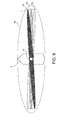
- Fig. 3 is a view schematically illustrating a process of detecting the target object by the underwater detection apparatus 1, illustrated with the ship S on which the underwater detection apparatus 1 is mounted.
- the sensor 3 of this embodiment performs a beamforming in cooperation with the transmission-and-reception device 5 and the signal processor 10 which are described later in detail, so as to perform detection within a fan area FA by electronically scanning a narrow beam NB (see Fig. 1 ), the fan area FA being a fan-shaped area within which the linear array of the sensor 3 has sensitivity (e.g., an area where ⁇ is between -60° and 60° by having the vertically downward direction as 0°).
- the fan area FA is thin (e.g., 6° in a thickness direction substantially perpendicular to the scanning direction) and, as illustrated in Fig. 3 , generated into a plane spreading downward from the ship S. Specifically, the fan area FA is generated to spread downward 2-dimensionally within a surface including both the direction of arrangement of the ultrasonic transducers 3a and the vertical direction. Further, since the sensor 3 is rotated within the horizontal plane by the motor 4 as described above, the fan area FA accordingly rotates in the same direction ( ⁇ direction in Fig. 3 ). Thus, according to the underwater detection apparatus 1 of this embodiment, the target object within 3-dimensional space below the ship (space surrounded by the dashed lines in Fig. 3 ) can be detected and a 3-dimensional position of the target object within the space can be estimated.
- the transmission-and-reception device 5 includes a transmitter 6 and a receiver 7.
- the transmitter 6 amplifies the frequency modulated transmission signal generated by the signal processor 10 to obtain a high-voltage transmission signal, and applies the high-voltage transmission signal to the projector 2.
- the receiver 7 amplifies the electric signal (e.g. a received signal) outputted by the sensor 3, and A/D converts the amplified received signal. Then, the receiver 7 outputs the received signal converted into a digital signal, to the signal processor 10. Specifically, the receiver 7 has a plurality of receive circuits (not illustrated), and each receive circuit performs the processing described above on the received signal obtained by electroacoustically converting the reflected wave received by the corresponding ultrasonic transducer 3a, and outputs the processed received signal to the signal processor 10.
- each receive circuit performs the processing described above on the received signal obtained by electroacoustically converting the reflected wave received by the corresponding ultrasonic transducer 3a, and outputs the processed received signal to the signal processor 10.
- the signal processor 10 generates the transmission signal (electric signal) and inputs it to the transmitter 6. Further, the signal processor 10 processes the received signal outputted by the receiver 7 to generate an image signal of the target object.
- the configuration of the signal processor 10 is described later in detail.
- the display unit 8 displays, on a display screen, an image corresponding to the image signal outputted by the signal processor 10.
- the display unit 8 3-dimensionally displays an underwater state below the ship.
- a user can estimate the underwater state below the ship (e.g., a single fish or a school of fish, undulation of the water bottom, whether the structural object, such as an artificial fish reef, exists, and a position thereof) by looking at the display screen.
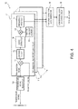
- Fig. 4 is a block diagram illustrating a configuration of the signal processor 10.
- the signal processor 10 includes a transmission signal generator 10a, a transmission-and-reception processor 11 (which may be also referred to as a reception processor or a reception processing means), a fan-area detection data generator 18 (which may be also referred to as a beamforming processor or a beamforming processing means), and a 3-dimensional echo data processor 19.
- the transmission signal generator 10a generates the transmission signal (which is typically an electric signal), basis of the transmission wave transmitted by the projector 2.
- the transmission signal generated by the transmission signal generator 10a is transmitted to the transmitter 6 and the transmission-and-reception processor 11.
- the transmission-and-reception processor 11 has a plurality of transmission-and-reception circuits 11a. Each transmission-and-reception circuit 11a receives the transmission signal generated by the transmission signal generator 10a and the received signal generated by the corresponding receive circuit (the received signal obtained by the corresponding ultrasonic transducer 3a). The transmission-and-reception circuit 11a performs signal processing on the received signal.
- Each transmission-and-reception circuit 11a includes a first multiplier 12, a low-pass filter 13, a signal extractor 14, a window function memory 15, a second multiplier 16, and a frequency analyzer 17. Note that, each transmission-and-reception circuit 11a performs the same processing except that the received signal input to each transmission-and-reception circuit is different as each received signal is generated based on a different ultrasonic transducer.
- the first multiplier 12 generates a beat signal based on the transmission signal generated by the transmission signal generator 10a and the received signals obtained from the ultrasonic waves received by the ultrasonic transducers 3a. Specifically, the first multiplier 12 combines (e.g. mixes or multiplies) the transmission signal with the received signals described above to generate the beat signal.
- Fig. 5 is a chart illustrating one example of the beat signal generated by the first multiplier 12.
- the low-pass filter 13 removes an unrequired signal component (which is typically a high frequency component) from the beat signal generated by the first multiplier 12.
- the signal extractor 14 extracts a signal from within a section so as to process the signal in a post process. Specifically, the signal extractor 14 sets the section to be processed to be a reception gate section, and sets the beat signal within the reception gate section to be the extracted beat signal.
- Figs. 6A and 6B are views for describing the generation of the extracted beat signal, in which Fig. 6A illustrates a waveform of the beat signal outputted from the low-pass filter (i.e., a waveform before the extracted beat signal is extracted), and Fig. 6B illustrates a waveform of the extracted beat signal extracted from the beat signal in Fig. 6A .
- the window function memory 15 stores a particular window function. Further, the second multiplier 16 multiplies the extracted beat signal by the particular window function stored in the window function memory 15.
- the frequency analyzer 17 analyzes the output result from the second multiplier 16 (the extracted beat signal multiplied by the window function) and generates data indicating an amplitude and a phase (amplitude spectrum and phase spectrum; hereinafter, they may comprehensively be referred to as the complex spectrum) at each frequency.
- Examples of the analyzing method include a Discrete Fourier Transform (DFT) and a Fast Fourier Transform (FFT). Note that, by multiplying the extracted beat signal by the window function as described above, side lobes of the complex spectrum generated by the frequency analyzer 17 can be reduced.
- DFT Discrete Fourier Transform
- FFT Fast Fourier Transform
- the complex spectrum corresponding to each ultrasonic transducer 3a is generated by the corresponding transmission-and-reception circuit 11a.
- the complex spectrum generated by the frequency analyzer 17 is outputted to the fan area detection data generator 18.
- the fan area detection data generator 18 converts a horizontal axis of the complex spectrum generated by each transmission-and-reception circuit 11a from a frequency into a distance (e.g. a distance from the ship) to generate echo data (e.g. complex amplitude data of the echo at each distance from the ship).
- a coefficient for the conversion from the frequency into the distance may be calculated to perform the conversion based on the sweeping bandwidth of the transmission signal, the sweeping time period of the transmission signal, and the underwater sound speed.
- the fan area detection data generator 18 performs a beamforming based on each echo data described above.
- the fan area detection data generator 18 is provided as a beamforming processor configured to perform the beamforming based on each echo data described above.
- the beamforming method a case of phasing addition is described.
- a reception beam NB oriented at the predetermined angle ⁇ can be formed.
- an echo intensity at each angle ⁇ can be obtained.
- the fan area detection data generator 18 can calculate echo intensities at respective positions of an area specified by a distance r and the angle ⁇ by obtaining the echo intensity at each angle ⁇ and each distance r.
- the echo intensity may be referred to as the fan area echo intensity.
- the rotational speed of the motor 4 may need to be set so that a time period for rotating by the angle corresponding to the thickness of the fan area FA becomes longer than a time period corresponding to the reception gate section at the transmission-and-reception processor 11.
- the rotational speed of the motor 4 may be set so that both of the time periods match with each other.
- the 3-dimensional echo data processor 19 combines each fan area echo intensity of every rotational angular position ⁇ ( ⁇ 1, ⁇ 2, ...) generated by the fan area detection data generator 18, and generates 3-dimensional echo data.
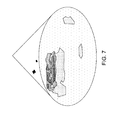
- Fig. 7 is a view illustrating one example of an image that is generated from the image signal based on the 3-dimensional echo data and displayed on the display unit 8.
- echoes from shallow positions are indicated by hatching with higher density
- echoes from deep positions are indicated by hatching with lower density. Note that, in the image of Fig. 7 , the hatching is applied to areas where the echo intensity is above a predetermined threshold, and hatching density is not related to echo intensity.
- a detection time required for detecting over a particular range with the underwater detection apparatus 1 of this embodiment is compared, through simulation, with a detection time for detecting over the particular range with a known (general) underwater detection apparatus (e.g. an underwater detection apparatus using mechanical scanning based on a pulse echo method).
- the simulation is performed under a condition that a rotation step is 6° (a rotational angle in a single step of ⁇ in Fig. 3 ), the number of rotation steps is 30, the detection range is 100m, a range resolution is 0.75m, and a CTFM sweep bandwidth is 15 kHz.
- the range resolution is set to have a similar specification to the general underwater detection apparatus, and the CTFM sweep bandwidth is set to be a bandwidth which is transmittable and receivable by an ultrasonic transducer adopted in the general underwater detection apparatus.
- the reception gate section can be set to 9ms.
- the rotational speed of the sensor is set to 9ms/6°.
- the underwater detection apparatus using mechanical scanning based on the pulse echo method is set to have a condition that a transmission beam is a fan beam same as the fan area FA, and the detection over the 3-dimensional space is performed by repeating a detection through electronic scan with a narrow reception beam within the fan beam, and a mechanical rotation of the transmission beam and the reception beam by a motor.
- the underwater sound speed is 1,500m/s
- a round-trip propagation of the detection range of 100m by the ultrasonic pulse requires 133ms. Therefore, the rotational speed of the projector and the sensor is 133ms/6°.
- the detection time is approximately 4,000ms; whereas in the case of the underwater detection apparatus 1 of this embodiment, the detection time is 270ms. Specifically, it was confirmed that with the underwater detection apparatus 1 of this embodiment, the detection time can significantly be shortened (at least to 1/10 in this simulation result) compared to the conventional method (the pulse echo method).
- the underwater detection apparatus 1 of this embodiment by performing the beamforming based on each beat signal generated based on the reflected wave received by each of the plurality of ultrasonic transducers 3a, the echo intensity within the fan area FA can be calculated.
- the sensor 3 does not need to be mechanically moved in order to obtain the echo intensity within the fan area FA. Therefore, the echo intensity within the 2-dimensional area can be obtained in a comparatively short time period.
- the sensor 3 is rotated using the motor 4 by a particular angle at a time to change the position of the fan beam formed by the sensor 3.
- the detection over the 3-dimensional space can be performed by the fan beam area echo intensity calculated for every angular position ⁇ , and a 3-dimensional position of the target object can be estimated.
- the receiving elements do not need to be arranged 2-dimensionally or 3-dimensionally as they are arranged in a conventional scanning sonar, and a number of receiving elements can be reduced. Therefore, the apparatus can be simplified.
- the underwater detection apparatus 1 detects the target object by using a CTFM method, compared to the case of adopting the pulse echo method, the amount of time to detect an object over a particular range can be shortened. More specifically, since the CTFM method is adopted, the underwater detection apparatus 1 can obtain the echo intensity within the fan area FA in a time period shorter than the time period required for the round-trip propagation of the detection range by the ultrasonic pulse. Thus, the echo intensity within the 2-dimensional area (fan area FA) can be obtained in a comparatively short time period, and as a result, the time period required for detecting the predetermined range can be shortened.
- a CTFM detection apparatus capable of detecting a 3-dimensional position of the target object in a comparatively short time period can be provided at low cost.
- the underwater detection apparatus 1 since the transmission beam has a 3-dimensional shape, a single transmission of the ultrasonic wave can cover the detection target area for the target object. In this manner, the projector 2 does not need to be set in motion in order to run through the entire detection area. Therefore, the apparatus can be simplified.
- the underwater detection apparatus 1 generates the beat signal by combining the transmission signal based on the waveform of the transmission wave, with the received signals based on the waveform of the reflected waves.
- the ultrasonic transducers 3a are linearly arranged to form the sensor 3 into the linear array. Therefore, compared to when the ultrasonic transducers are arranged 2-dimensionally or 3-dimensionally, the number of the ultrasonic transducers 3a can be reduced.
- a CTFM detection apparatus capable of detecting 3-dimensional space can be constructed with a comparatively simple configuration.
- the senor 3 is rotated about the axis perpendicular to the receiving surface of the ultrasonic transducers 3a. Therefore, the detection can suitably be performed over a 3-dimensional area extending from the perpendicular axis.
- the sensor 3 is set in motion in the direction both perpendicular to the direction of arrangement of the ultrasonic transducers 3a and within the receiving surface of the ultrasonic transducers 3a. In this manner, the rotational direction of the sensor 3 being perpendicular to the 2-dimensional fan area FA reduces overlapping of the fan area FA that moves over time. Thus, the detection can be performed over a wide area in a comparatively short time period.
- the projector 2 With the underwater detection apparatus 1, the projector 2 generates the transmission beam having the conical shape, which in some embodiments may be the right conical shape. Therefore, the detection can be performed over a wide area below the ship.
- an underwater detection apparatus capable of detecting a 3-dimensional position of the target object underwater in a comparatively short time period can be provided at low cost.
Landscapes
- Engineering & Computer Science (AREA)
- Physics & Mathematics (AREA)
- Radar, Positioning & Navigation (AREA)
- Remote Sensing (AREA)
- Acoustics & Sound (AREA)
- Computer Networks & Wireless Communication (AREA)
- General Physics & Mathematics (AREA)
- Multimedia (AREA)
- Measurement Of Velocity Or Position Using Acoustic Or Ultrasonic Waves (AREA)
Applications Claiming Priority (1)
| Application Number | Priority Date | Filing Date | Title |
|---|---|---|---|
| JP2014226658A JP2016090452A (ja) | 2014-11-07 | 2014-11-07 | 探知装置及び水中探知装置 |
Publications (1)
| Publication Number | Publication Date |
|---|---|
| EP3018493A1 true EP3018493A1 (de) | 2016-05-11 |
Family
ID=54366151
Family Applications (1)
| Application Number | Title | Priority Date | Filing Date |
|---|---|---|---|
| EP15193061.7A Withdrawn EP3018493A1 (de) | 2014-11-07 | 2015-11-04 | Ctfm-detektionsvorrichtung und unterwasserdetektionsvorrichtung |
Country Status (3)
| Country | Link |
|---|---|
| US (1) | US20160131759A1 (de) |
| EP (1) | EP3018493A1 (de) |
| JP (1) | JP2016090452A (de) |
Cited By (1)
| Publication number | Priority date | Publication date | Assignee | Title |
|---|---|---|---|---|
| CN107544071A (zh) * | 2016-06-23 | 2018-01-05 | 古野电气株式会社 | 水中探测系统 |
Families Citing this family (12)
| Publication number | Priority date | Publication date | Assignee | Title |
|---|---|---|---|---|
| US10310062B2 (en) | 2016-01-25 | 2019-06-04 | Garmin Switzerland Gmbh | Frequency steered sonar hardware |
| US10890660B2 (en) * | 2016-10-12 | 2021-01-12 | Garmin Switzerland Gmbh | Frequency steered sonar array orientation |
| JP6761893B2 (ja) | 2017-03-10 | 2020-09-30 | 古野電気株式会社 | 超音波探知装置及び超音波探知方法 |
| JP7051625B2 (ja) * | 2018-07-12 | 2022-04-11 | 古野電気株式会社 | 水中探知装置及び水中探知方法 |
| JP7246251B2 (ja) | 2019-05-21 | 2023-03-27 | 古野電気株式会社 | 水中探知装置、および、水中探知方法 |
| JP2021096210A (ja) * | 2019-12-19 | 2021-06-24 | ソニーグループ株式会社 | 信号処理装置及び信号処理方法、並びに3次元測定装置 |
| US11370516B2 (en) | 2020-05-22 | 2022-06-28 | Mark Alan Ridl | Motorized rotating transducer mount |
| US11885918B2 (en) | 2020-10-19 | 2024-01-30 | Garmin International, Inc. | Sonar system with dynamic power steering |
| CN112904347B (zh) * | 2021-01-19 | 2023-05-26 | 鹏城实验室 | 成像系统和方法 |
| CN113390374B (zh) * | 2021-06-10 | 2023-08-01 | Oppo广东移动通信有限公司 | 生态环境信息的确定方法、装置、探测设备和存储介质 |
| JP7714173B2 (ja) * | 2021-09-14 | 2025-07-29 | 国立大学法人 琉球大学 | 海中音響測位システム |
| CN120722331B (zh) * | 2025-08-22 | 2025-11-11 | 中国海洋大学 | 一种连续波主动声呐探测系统的直达波信号抑制方法 |
Citations (4)
| Publication number | Priority date | Publication date | Assignee | Title |
|---|---|---|---|---|
| EP0087318A2 (de) * | 1982-02-24 | 1983-08-31 | Kabushiki Kaisha Toshiba | Gerät für Ultraschalldiagnostik |
| US20050007882A1 (en) * | 2003-07-11 | 2005-01-13 | Blue View Technologies, Inc. | Systems and methods implementing frequency-steered acoustic arrays for 2D and 3D imaging |
| GB2418020A (en) * | 2003-05-09 | 2006-03-15 | Furuno Electrical Company Ltd | Ultrasonic wave transmitter/receiver |
| US20130215719A1 (en) | 2012-02-22 | 2013-08-22 | Johnson Outdoors Inc. | 360 Degree Imaging Sonar and Method |
-
2014
- 2014-11-07 JP JP2014226658A patent/JP2016090452A/ja active Pending
-
2015
- 2015-11-04 EP EP15193061.7A patent/EP3018493A1/de not_active Withdrawn
- 2015-11-05 US US14/933,483 patent/US20160131759A1/en not_active Abandoned
Patent Citations (4)
| Publication number | Priority date | Publication date | Assignee | Title |
|---|---|---|---|---|
| EP0087318A2 (de) * | 1982-02-24 | 1983-08-31 | Kabushiki Kaisha Toshiba | Gerät für Ultraschalldiagnostik |
| GB2418020A (en) * | 2003-05-09 | 2006-03-15 | Furuno Electrical Company Ltd | Ultrasonic wave transmitter/receiver |
| US20050007882A1 (en) * | 2003-07-11 | 2005-01-13 | Blue View Technologies, Inc. | Systems and methods implementing frequency-steered acoustic arrays for 2D and 3D imaging |
| US20130215719A1 (en) | 2012-02-22 | 2013-08-22 | Johnson Outdoors Inc. | 360 Degree Imaging Sonar and Method |
Non-Patent Citations (2)
| Title |
|---|
| CTFM SONAR SS330, 29 August 2014 (2014-08-29), Retrieved from the Internet <URL:http://www.sunwest-tech.com/SS300%20Broch%20-%20REV%20G.pdf> |
| MASAHUMI EMURA: "Acoustic Imaging using CTFM Sonar", THE JOURNAL OF ACOUSTICAL SOCIETY OF JAPAN, March 2012 (2012-03-01) |
Cited By (1)
| Publication number | Priority date | Publication date | Assignee | Title |
|---|---|---|---|---|
| CN107544071A (zh) * | 2016-06-23 | 2018-01-05 | 古野电气株式会社 | 水中探测系统 |
Also Published As
| Publication number | Publication date |
|---|---|
| JP2016090452A (ja) | 2016-05-23 |
| US20160131759A1 (en) | 2016-05-12 |
Similar Documents
| Publication | Publication Date | Title |
|---|---|---|
| EP3018493A1 (de) | Ctfm-detektionsvorrichtung und unterwasserdetektionsvorrichtung | |
| EP3018494A1 (de) | Ctfm-detektionsvorrichtung und unterwasserdetektionsvorrichtung | |
| Colbo et al. | A review of oceanographic applications of water column data from multibeam echosounders | |
| US10215849B2 (en) | CTFM detection apparatus and underwater detection apparatus | |
| US20130083628A1 (en) | Imaging system and method | |
| US11320534B2 (en) | Ultrasonic detecting device and ultrasonic detecting method | |
| JP2014178320A (ja) | ソナートランスデューサ組立体 | |
| US20220171056A1 (en) | Techniques for sonar data processing | |
| US9636086B2 (en) | Three dimensional (3D) transverse oscillation vector velocity ultrasound imaging | |
| WO2017015741A1 (en) | Forward scanning sonar system and method with angled fan beams | |
| US9474510B2 (en) | Ultrasound and system for forming an ultrasound image | |
| JP7262298B2 (ja) | 水中探知装置、および、水中探知方法 | |
| EP3570069A1 (de) | Verfahren zum komprimieren von strahlgeformten sonardaten | |
| EP3325997A1 (de) | Vorwärts abtastendes sonarsystem und verfahren mit abgewinkelten lüfterstrahlen | |
| JP5767002B2 (ja) | 超音波送受信装置、および魚量検出方法 | |
| WO2014147122A1 (en) | Imaging system and method | |
| Wei et al. | Theoretical and experimental study on multibeam synthetic aperture sonar | |
| JP7813244B2 (ja) | 物標検出装置および物標検出方法 | |
| JP2012189499A (ja) | 信号処理装置、探査装置、信号処理プログラム、及び信号処理方法 | |
| JP2016038323A (ja) | 探知装置、探知方法、およびプログラム | |
| JP6088165B2 (ja) | 探知装置、探知方法及び探知プログラム | |
| Kortbek et al. | P2b-1 synthetic aperture focusing applied to imaging using a rotating single element transducer | |
| JP7719780B2 (ja) | 指示可能なパラメトリック音響測深機、及び水中環境の海底下の一部を特徴付けるための方法 | |
| JP2012112922A (ja) | 探知装置、水中探知装置、探知方法及びプログラム | |
| JP6321472B2 (ja) | 信号処理装置、水中探知装置、レーダ装置、信号処理方法、及び信号処理プログラム |
Legal Events
| Date | Code | Title | Description |
|---|---|---|---|
| PUAI | Public reference made under article 153(3) epc to a published international application that has entered the european phase |
Free format text: ORIGINAL CODE: 0009012 |
|
| AK | Designated contracting states |
Kind code of ref document: A1 Designated state(s): AL AT BE BG CH CY CZ DE DK EE ES FI FR GB GR HR HU IE IS IT LI LT LU LV MC MK MT NL NO PL PT RO RS SE SI SK SM TR |
|
| AX | Request for extension of the european patent |
Extension state: BA ME |
|
| 17P | Request for examination filed |
Effective date: 20161102 |
|
| RBV | Designated contracting states (corrected) |
Designated state(s): AL AT BE BG CH CY CZ DE DK EE ES FI FR GB GR HR HU IE IS IT LI LT LU LV MC MK MT NL NO PL PT RO RS SE SI SK SM TR |
|
| GRAP | Despatch of communication of intention to grant a patent |
Free format text: ORIGINAL CODE: EPIDOSNIGR1 |
|
| INTG | Intention to grant announced |
Effective date: 20200110 |
|
| STAA | Information on the status of an ep patent application or granted ep patent |
Free format text: STATUS: THE APPLICATION IS DEEMED TO BE WITHDRAWN |
|
| 18D | Application deemed to be withdrawn |
Effective date: 20200603 |