EP3020444B1 - Cathéter - Google Patents
Cathéter Download PDFInfo
- Publication number
- EP3020444B1 EP3020444B1 EP14822799.4A EP14822799A EP3020444B1 EP 3020444 B1 EP3020444 B1 EP 3020444B1 EP 14822799 A EP14822799 A EP 14822799A EP 3020444 B1 EP3020444 B1 EP 3020444B1
- Authority
- EP
- European Patent Office
- Prior art keywords
- area
- end side
- base end
- leading end
- tapered
- Prior art date
- Legal status (The legal status is an assumption and is not a legal conclusion. Google has not performed a legal analysis and makes no representation as to the accuracy of the status listed.)
- Active
Links
Images


Classifications
-
- A—HUMAN NECESSITIES
- A61—MEDICAL OR VETERINARY SCIENCE; HYGIENE
- A61M—DEVICES FOR INTRODUCING MEDIA INTO, OR ONTO, THE BODY; DEVICES FOR TRANSDUCING BODY MEDIA OR FOR TAKING MEDIA FROM THE BODY; DEVICES FOR PRODUCING OR ENDING SLEEP OR STUPOR
- A61M25/00—Catheters; Hollow probes
- A61M25/01—Introducing, guiding, advancing, emplacing or holding catheters
- A61M25/0105—Steering means as part of the catheter or advancing means; Markers for positioning
-
- A—HUMAN NECESSITIES
- A61—MEDICAL OR VETERINARY SCIENCE; HYGIENE
- A61M—DEVICES FOR INTRODUCING MEDIA INTO, OR ONTO, THE BODY; DEVICES FOR TRANSDUCING BODY MEDIA OR FOR TAKING MEDIA FROM THE BODY; DEVICES FOR PRODUCING OR ENDING SLEEP OR STUPOR
- A61M25/00—Catheters; Hollow probes
- A61M25/0043—Catheters; Hollow probes characterised by structural features
-
- A—HUMAN NECESSITIES
- A61—MEDICAL OR VETERINARY SCIENCE; HYGIENE
- A61M—DEVICES FOR INTRODUCING MEDIA INTO, OR ONTO, THE BODY; DEVICES FOR TRANSDUCING BODY MEDIA OR FOR TAKING MEDIA FROM THE BODY; DEVICES FOR PRODUCING OR ENDING SLEEP OR STUPOR
- A61M25/00—Catheters; Hollow probes
- A61M25/0021—Catheters; Hollow probes characterised by the form of the tubing
- A61M25/0023—Catheters; Hollow probes characterised by the form of the tubing by the form of the lumen, e.g. cross-section, variable diameter
- A61M25/0026—Multi-lumen catheters with stationary elements
-
- A—HUMAN NECESSITIES
- A61—MEDICAL OR VETERINARY SCIENCE; HYGIENE
- A61M—DEVICES FOR INTRODUCING MEDIA INTO, OR ONTO, THE BODY; DEVICES FOR TRANSDUCING BODY MEDIA OR FOR TAKING MEDIA FROM THE BODY; DEVICES FOR PRODUCING OR ENDING SLEEP OR STUPOR
- A61M25/00—Catheters; Hollow probes
- A61M25/01—Introducing, guiding, advancing, emplacing or holding catheters
- A61M25/09—Guide wires
-
- A—HUMAN NECESSITIES
- A61—MEDICAL OR VETERINARY SCIENCE; HYGIENE
- A61M—DEVICES FOR INTRODUCING MEDIA INTO, OR ONTO, THE BODY; DEVICES FOR TRANSDUCING BODY MEDIA OR FOR TAKING MEDIA FROM THE BODY; DEVICES FOR PRODUCING OR ENDING SLEEP OR STUPOR
- A61M25/00—Catheters; Hollow probes
- A61M25/10—Balloon catheters
-
- A—HUMAN NECESSITIES
- A61—MEDICAL OR VETERINARY SCIENCE; HYGIENE
- A61M—DEVICES FOR INTRODUCING MEDIA INTO, OR ONTO, THE BODY; DEVICES FOR TRANSDUCING BODY MEDIA OR FOR TAKING MEDIA FROM THE BODY; DEVICES FOR PRODUCING OR ENDING SLEEP OR STUPOR
- A61M25/00—Catheters; Hollow probes
- A61M25/0021—Catheters; Hollow probes characterised by the form of the tubing
- A61M25/0023—Catheters; Hollow probes characterised by the form of the tubing by the form of the lumen, e.g. cross-section, variable diameter
- A61M25/0026—Multi-lumen catheters with stationary elements
- A61M2025/0039—Multi-lumen catheters with stationary elements characterized by lumina being arranged coaxially
-
- A—HUMAN NECESSITIES
- A61—MEDICAL OR VETERINARY SCIENCE; HYGIENE
- A61M—DEVICES FOR INTRODUCING MEDIA INTO, OR ONTO, THE BODY; DEVICES FOR TRANSDUCING BODY MEDIA OR FOR TAKING MEDIA FROM THE BODY; DEVICES FOR PRODUCING OR ENDING SLEEP OR STUPOR
- A61M25/00—Catheters; Hollow probes
- A61M25/0043—Catheters; Hollow probes characterised by structural features
- A61M2025/0059—Catheters; Hollow probes characterised by structural features having means for preventing the catheter, sheath or lumens from collapsing due to outer forces, e.g. compressing forces, or caused by twisting or kinking
-
- A—HUMAN NECESSITIES
- A61—MEDICAL OR VETERINARY SCIENCE; HYGIENE
- A61M—DEVICES FOR INTRODUCING MEDIA INTO, OR ONTO, THE BODY; DEVICES FOR TRANSDUCING BODY MEDIA OR FOR TAKING MEDIA FROM THE BODY; DEVICES FOR PRODUCING OR ENDING SLEEP OR STUPOR
- A61M25/00—Catheters; Hollow probes
- A61M25/01—Introducing, guiding, advancing, emplacing or holding catheters
- A61M2025/0183—Rapid exchange or monorail catheters
-
- A—HUMAN NECESSITIES
- A61—MEDICAL OR VETERINARY SCIENCE; HYGIENE
- A61M—DEVICES FOR INTRODUCING MEDIA INTO, OR ONTO, THE BODY; DEVICES FOR TRANSDUCING BODY MEDIA OR FOR TAKING MEDIA FROM THE BODY; DEVICES FOR PRODUCING OR ENDING SLEEP OR STUPOR
- A61M25/00—Catheters; Hollow probes
- A61M25/10—Balloon catheters
- A61M25/104—Balloon catheters used for angioplasty
Definitions
- the present invention relates to a catheter.
- the guide wire that is introduced into the human body in advance is inserted through the lumen of the inner tube.
- the user introduces the balloon catheter into the human body in a state in which the guide wire is inserted through the lumen of the inner tube.
- the RX type is a type in which the guide wire can be led to the outside from a midway position in the axial line direction of the outer tube.
- a guide wire port which penetrates a peripheral wall portion of the outer tube, is formed in a midway position in the axial line direction of the outer tube.
- the lumen of the inner tube is open to the outside of the catheter via the guide wire port.
- the guide wire that is introduced inside the inner tube from the leading end portion of the inner tube is introduced to the outside of the catheter via the guide wire port.
- a section of the core wire further to a base end side than the section formed with the narrow diameter be formed such that an outer diameter becomes gradually larger from the leading end side toward the base end side. It is therefore conceivable that the core wire be formed, for example, such that the outer diameter becomes slowly larger at a constant rate from the leading end side toward the base end side. In this case, the rigidity of the core wire can be gradually reduced from the base end side to the leading end side, and it is possible to improve a kink resistance performance.
- Patent Literature 1 Japanese Laid-Open Patent Publication No. 2008-200317 . See as well EP2495006 A1 , US2012296367 A1 and WO0145788 A1 .
- the core wire is disposed across the guide wire port in the axial line direction, rigidity is imparted in the vicinity on a base end side of the guide wire port by the core wire.
- an effect can be anticipated that the local change in rigidity at the location of formation of the guide wire port is suppressed.
- the outer diameter of the above-described core wire becomes gradually larger at a constant rate from a narrow diameter area disposed further to the leading end side than the guide wire port toward the base end side. It is thus difficult to obtain a sufficient size of the outer diameter in the vicinity on the base end side of the guide wire port. As a result, it is conceivable that it is difficult to impart sufficient rigidity in the vicinity on the base end side. Therefore, in the above-described core wire, the above-described problem that the pressing force is not properly transmitted to the leading end side when the catheter is introduced into the human body is still not resolved, and an improvement is demanded.
- a catheter of a first aspect of the invention is characterized by including: a tube having a lumen in an interior thereof; a guide wire port formed in a midway position in an axial line direction of the tube, the guide wire port penetrating a peripheral wall portion surrounding the lumen; and a core wire inserted into the lumen and extending across the guide wire port in the axial line direction.
- the core wire includes a leading end side area, which is an area positioned further to a leading end side than the guide wire port, and a tapered area, which is an area further to a base end side than the leading end side area and which is formed such that a cross-sectional area thereof in a direction orthogonal to the axial line direction becomes continuously larger from the leading end side toward the base end side.
- the tapered area includes a first tapered area, which is an area extending from a base end of the leading end side area toward the base end side, and which is an area including a same position as the guide wire port in the axial line direction, and a second tapered area, which is an area extending from a base end of the first tapered area toward the base end side.
- a rate of increase of the cross-sectional area from the leading end side toward the base end side in the first tapered area is larger than a rate of increase of the cross-sectional area from the leading end side toward the base end side in the second tapered area.
- the core wire is provided with the leading end side area that is provided further to the leading end side than the guide wire port, and with the tapered area that is provided further to the base end side than a leading end area.
- the tapered area has a first tapered area, which is an area including the same position as the guide wire port in the axial line direction, and a second tapered area, which is an area further to the base end side than the first tapered area.
- a rate of increase of the cross-sectional area from the leading end side toward the base end side is larger in the first tapered area than in the second tapered area.
- the catheter of a second aspect of the invention is characterized in that a boundary portion between the first tapered area and the second tapered area is positioned further to the leading end side than a center of the tapered area in the axial line direction.
- the cross-sectional area of the boundary portion between the first tapered area and the second tapered area is the same, when a comparison of magnitudes of the rate of increase of the cross-sectional area from the leading end side to the base end side in the first tapered area is made for a case in which the boundary portion is positioned to the leading end side in the tapered area, and for a case in which the boundary portion is positioned to the base end side, it is conceivable that the rate of increase of the cross-sectional area is larger in the former case than in the latter case.
- the present invention causes the boundary portion between the first tapered area and the second tapered area to be positioned further to the leading end side than a center position of the tapered area in the axial line direction.
- the catheter of a third aspect of the invention is characterized in that the boundary portion is positioned further to the leading end side than a location positioned to the base end side, from a leading end portion of the tapered area, by a distance of 1/4 of a total length of the tapered area.
- the boundary portion between the first tapered area and the second tapered area is positioned further to the leading end side than the location positioned to the base end side, from the leading end portion of the tapered area, by the distance of 1/4 of the total length of the tapered area. Accordingly, it is possible to make the rate of increase from the leading end side toward the base end side of the cross-sectional area of the first tapered area even larger than in the second aspect of the invention. In this case, it is possible to even further enlarge the cross-sectional area of the core wire in the position in the vicinity on the base end side of the guide wire port in the axial line direction. It is thus possible to even further increase the rigidity of the core wire. As a result, it is possible to even further improve the transmissibility of the pressing force when the catheter is introduced into the human body.
- the cross-sectional area of the boundary portion is larger than the mean value of the cross-sectional areas of both ends of the tapered area in the axial line direction.
- the cross-sectional area of the boundary portion is equal to or smaller than the mean value of the above-described cross-sectional areas, it is possible to increase the rate at which the cross-sectional area of the first tapered area increases from the leading end side toward the base end side.
- the difference between the rates of increase of the cross-sectional area of the first tapered area and the second tapered area is the same as or substantially the same as the difference between the rates of increase of the cross-sectional area of the second tapered area and the base end side area.
- local changes (amounts) that occur in the rate of increase of the cross-sectional area in the boundary portion between the first tapered area and the second tapered area and the boundary portion between the second tapered area and the base end side area, respectively can be made the same.
- local changes in the rate of increase of the cross-sectional area occurring respectively in each of the boundary portions can be uniformly distributed to each of the boundary portions.
- the catheter of a sixth aspect of the invention is characterized by including: an outer tube corresponding to the tube, the outer tube internally having a fluid lumen corresponding to the lumen; an inner tube inserted into the fluid lumen in a state in which a part of the inner tube extends further to the leading end side than a leading end of the outer tube, the inner tube having a guide wire lumen through which the guide wire is insertable, and a base end portion of which communicates with the guide wire port; and a balloon, which covers, from the outside, the part of the inner tube extending from the leading end of the outer tube, and a base end portion of which is connected to a leading end portion of the outer tube.
- the leading end side area of the core wire is inserted into the fluid lumen between an outer peripheral surface of the inner tube and an inner peripheral surface of the outer tube.
- the balloon catheter is provided with the outer tube and the inner tube.
- the inner tube is inserted into the fluid lumen of the outer tube.
- the fluid flows between the outer peripheral surface of the inner tube and the inner peripheral surface of the outer tube.
- the balloon catheter of the first aspect of the invention it is possible to enlarge the cross-sectional area of the core wire in the position in the vicinity on the base end side of the guide wire port.
- a through-flow performance of the compressed fluid is secured, and it is possible to yet further improve the transmissibility of the pressing force when the balloon catheter 10 is introduced into the human body.
- a balloon catheter provided with a balloon that can inflate and deflate is embodied.
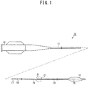
- Fig. 1 is an overall side view showing a configuration of the balloon catheter.
- a balloon catheter 10 is provided with a catheter shaft 11, a hub 12, and a balloon 13.
- the hub 12 is attached to a base end portion (a proximal end portion) of the catheter shaft 11.
- the balloon 13 is attached to a leading end side (a distal end side) of the catheter shaft 11.
- the respective shafts 17 to 19 are the proximal shaft 17, the mid-shaft 18, and the distal shaft 19, in that order from the base end side.
- the proximal shaft 17 is formed of a metal, such as an Ni-Ti alloy, stainless steel or the like.
- a base end portion of the proximal shaft 17 is connected to the hub 12.
- the mid-shaft 18 is formed of a thermoplastic polyamide elastomer.
- the rigidity of the mid-shaft 18 is lower than the rigidity of the proximal shaft 17.
- the distal shaft 19 is formed of a thermoplastic polyamide elastomer.
- the rigidity of the distal shaft 19 is lower than the rigidity of the mid-shaft 18.
- a guide wire port 21 is formed at a connection section of the outer shaft 15 to the inner shaft 16.
- Fig. 2 is a vertical cross-section view showing the structure in the vicinity of the guide wire port 21.
- Fig. 2 shows an area C1 shown in Fig. 1 .
- the balloon 13 is provided such that it covers, from the outside, the inner shaft 16 extending from the leading end of the outer shaft 15.
- the balloon 13 is formed of a thermoplastic polyamide elastomer.
- the balloon 13 may be formed of another thermoplastic synthetic resin, such as polyethylene, polypropylene or the like.
- Abase end portion of the balloon 13 is connected to a leading end portion of the outer shaft 15.
- the balloon 13 covers, from the outside, the inner shaft 16 extending from the leading end of the outer shaft 15, and the base end portion of the balloon 13 is connected to the leading end portion of the outer shaft 15.
- a leading end portion of the balloon 13 is connected to a leading end portion of the inner shaft 16.
- the interior of the balloon 13 is communicated with the hub 12, via the outer tube hole 15a of the outer shaft 15.
- a compressed fluid that is supplied via the hub 12 is supplied to the balloon 13 via the outer tube hole 15a.
- the outer tube hole 15a functions as a fluid lumen to cause the compressed fluid to flow.
- the balloon catheter 10 is provided with a core wire 30.
- the core wire 30 is provided in the balloon catheter 10 with the object of improving rigidity and the like of the catheter 10.
- a configuration of the core wire 30 will be explained with reference to Fig. 2 and Fig. 3 .
- Fig. 3 (a) is a side view showing the configuration of the core wire 30
- Fig. 3 (b) is an enlarged side view showing an enlarged section of the core wire 30.
- the core wire 30 is a linear member.
- the core wire 30 is formed of a metal material, for example.
- the core wire 30 is formed of stainless steel.
- a transverse cross-section of the core wire 30 has a circular shape. As shown in Fig. 3 (a) , the core wire 30 is formed such that the outer diameter on the leading end side is smaller than the outer diameter on the base end side. As a result, the rigidity of the core wire 30 is reduced the further toward the leading end side from the base end side.
- the transverse cross-section is a cross-section perpendicular to the axial line direction of the core wire 30.
- the core wire 30 is provided with a leading end side area 31, a tapered area 32, and a base end side area 33.
- the leading end side area 31 is an area extending from the leading end toward a base end side of the core wire 30.
- the leading end side area 31 is an area positioned further to the leading end side than the guide wire port 21.
- the tapered area 32 is an area provided continuously toward the base end side from the leading end side area 31.
- the tapered area 32 is an area extending from a base end of the leading end side area 31 toward the base end side.
- the base end side area 33 is an area provided continuously toward the base end side from the tapered area 32.
- the base end side area 33 is an area extending from a base end of the tapered area 32 toward the base end side.
- the base end side area 33 is an area including a base end portion of the core wire 30.
- the leading end side area 31 is the area including the section with the smallest outer diameter.
- the leading end side area 31 is formed in a tapered shape. Therefore, an outer diameter of the leading end area 31 gradually becomes larger from the leading end side toward the base end side.
- a length L1 of the leading end side area 31 in the axial line direction is set to be 80 mm. Note that the leading end side area 31 need not necessarily be formed in the tapered shape.
- the leading end side area 31 may be a columnar area whose outer diameter is constant across the whole area in the axial line direction.
- An outer diameter of the base end side area 33 is constant across the whole area in the axial line direction. Specifically, in contrast to the leading end side area 31 and the tapered area 32, the base end side area 33 is a non-tapered area. A length of the base end side area 33 in the axial line direction is sufficiently longer than the leading end side area 31 and the taper area 32. In the present embodiment, the length of the base end side area 33 is set to be between 700 and 1500 mm.
- the tapered area 32 has a first tapered area 34 and a second tapered area 35.
- the first tapered area 34 is an area provided continuously toward the base end side from the leading end side area 31.
- the first tapered area 34 is an area extending from the base end of the leading end side area 31 toward the base end side.
- the second tapered area 35 is an area provided continuously toward the base end side from the first tapered area 34.
- the second tapered area 35 is an area extending from a base end of the first tapered area 34 toward the base end side.
- a rate of increase of the outer diameter from the leading end side to the base end side is comparatively larger than that of the second tapered area 35.
- the length L2 of the first tapered area 34 in the axial line direction is shorter than the length L3 of the second tapered area 35 in the axial line direction.
- L2/L3 is smaller than 1 (0 ⁇ L2/L3 ⁇ 1).
- L2/L3 is smaller than 1/3, and more specifically, is smaller than 1/5.
- a transverse cross-sectional area of the boundary portion 36 is larger than a mean value of a transverse cross-sectional area of the leading end portion of the tapered area 32 and a transverse cross-sectional area of the base end portion of the tapered area 32.
- the transverse cross-sectional area of the boundary portion 36 is larger than a mean value of a minimum transverse cross-sectional area of the tapered area 32 and a maximum transverse cross-sectional area of the tapered area 32.
- the rate of increase of the transverse cross-sectional area from the leading end side to the base end side in the tapered areas 34 and 35 is expressed as a variation amount of the transverse cross-sectional area per unit length in the axial line direction.
- the rate of increase of the transverse cross-sectional area from the leading end side to the base end side in the tapered areas 34 and 35 is also referred to as a transverse cross-section increase ratio.
- the variation amount of the transverse cross-sectional area per unit length in the axial line direction is an increase amount of the transverse cross-sectional area when seen from the leading end side toward the base end side.
- magnitude relationships of the transverse cross-sectional area increase ratios ⁇ S1 to ⁇ S3 of each of the first tapered area 34, the second tapered area 35, and the base end side area 33 are: ⁇ S1 > ⁇ S2 > ⁇ S3.
- the rigidity of the area further to the leading end side than the guide wire port 21, through which the guide wire G is inserted is higher than the rigidity of the area further to the base end side than the guide wire port 21, through which the guide wire G is not inserted.
- the rigidity of the balloon catheter 10 changes locally. Since the rigidity of the balloon catheter 10 changes locally in the axial line direction, it is possible that a force pressing the balloon catheter 10 from the base end side is not properly transmitted to the leading end side.
- the rate of increase of the transverse cross-sectional area from the leading end side toward the base end side in the first tapered area 34 is compared between a first configuration in which the boundary portion 36 between the first tapered area 34 and the second tapered area 35 is positioned to the leading end side in the tapered area 32, and a second configuration in which the boundary portion 36 between the first tapered area 34 and the second tapered area 35 is positioned to the base end side in the tapered area 32, it is conceivable that the rate of increase is larger in the first configuration than in the second configuration. Note that the transverse cross-sectional area of the boundary portion 36 in the first configuration and the transverse cross-sectional area of the boundary portion 36 in the second configuration are the same.
- the boundary portion 36 is positioned further to the leading end side than the center position of the tapered area 32, and the transverse cross-sectional area of the boundary portion 36 is larger than a mean value of the transverse cross-sectional areas of both end portions of the tapered area 32 in the axial line direction.
- the transverse cross-sectional area of the boundary portion 36 is equal to or less than the mean value of the transverse cross-sectional areas of both end portions of the tapered area 32 in the axial line direction, it is possible to make the rate at which the transverse cross-sectional area of the first tapered area 34 increases from the leading end side toward the base end side larger.
- the difference between the transverse cross-sectional area increase ratio ⁇ S1 of the first tapered area 34 and the transverse cross-sectional area increase ratio ⁇ S2 of the second tapered area 35 is the same as the difference between the transverse cross-sectional area increase ratio ⁇ S2 of the second tapered area 35 and the transverse cross-sectional area increase ratio ⁇ S3 of the base end side area 33. Accordingly, changes (amounts) that occur locally in the rate of increase of the transverse cross-sectional area in the boundary portion 36 between the first tapered area 34 and the second tapered area 35 and the boundary portion 37 between the second tapered area 35 and the base end side area 33, respectively, can be made the same.
- the outer shaft 15 corresponds to an "outer tube” and a "tube.”
- the inner shaft 16 corresponds to "an inner tube.”
- the outer tube hole 15a corresponds to a "lumen.”
- the present invention is not limited to the above-described embodiment, and may be executed in the following manner, for example.
Landscapes
- Health & Medical Sciences (AREA)
- Life Sciences & Earth Sciences (AREA)
- Heart & Thoracic Surgery (AREA)
- Biomedical Technology (AREA)
- Engineering & Computer Science (AREA)
- Anesthesiology (AREA)
- Pulmonology (AREA)
- Biophysics (AREA)
- Hematology (AREA)
- Animal Behavior & Ethology (AREA)
- General Health & Medical Sciences (AREA)
- Public Health (AREA)
- Veterinary Medicine (AREA)
- Child & Adolescent Psychology (AREA)
- Media Introduction/Drainage Providing Device (AREA)
Claims (6)
- Cathéter (10) comprenant :un tube (15) ayant un lumen (15a) en son intérieur et une partie de paroi périphérique (23) entourant le lumen ;un orifice (21) de fil-guide formé à une position à mi-chemin dans une direction de ligne axiale du tube, l'orifice de fil-guide pénétrant dans la partie de paroi périphérique ; etun fil d'âme (30) inséré dans le lumen et s'étendant à travers l'orifice de fil-guide dans la direction de ligne axiale ;et caractérisé en ce quele fil d'âme comprendune zone latérale (31) d'extrémité avant, qui est une zone positionnée plus loin d'un côté d'extrémité avant que l'orifice de fil-guide, etune zone conique (32) qui est une zone plus éloignée d'un côté d'extrémité de base que la zone latérale d'extrémité avant et qui est formée de telle sorte qu'une aire de section droite de celle-ci, dans une direction orthogonale à la direction de ligne axiale, devienne continuellement plus grande depuis le côté d'extrémité avant vers le côté d'extrémité de base,la zone conique comprendune première zone conique (34), qui est une zone s'étendant depuis une extrémité de base de la zone latérale d'extrémité avant vers le côté d'extrémité de base, et qui est une zone comprenant une même position que l'orifice de fil-guide dans la direction de ligne axiale, etune seconde zone conique (35), qui est une zone s'étendant depuis une extrémité de base de la première zone conique vers le côté d'extrémité de base, etun taux d'accroissement de l'aire de section droite depuis le côté d'extrémité avant vers le côté d'extrémité de base dans la première zone conique est plus grand qu'un taux d'accroissement de l'aire de section droite du côté d'extrémité avant vers le côté d'extrémité de base dans la seconde zone conique.
- Cathéter selon la revendication 1, caractérisé en ce que
une partie limite (36) entre la première zone conique et la seconde zone conique est positionnée plus loin du côté d'extrémité avant qu'un centre de la zone conique dans la direction de ligne axiale. - Cathéter selon la revendication 2, caractérisé en ce que
la partie limite est positionnée plus loin du côté d'extrémité avant qu'un emplacement positionné du côté d'extrémité de base, à partir d'une partie d'extrémité avant de la zone conique, d'une distance de 1/4 d'une longueur totale de la zone conique. - Cathéter selon la revendication 2 ou 3, caractérisé en ce que
l'aire de la section droite de la partie limite est plus grande qu'une valeur moyenne des aires de section droite des deux extrémités de la zone conique dans la direction de ligne axiale. - Cathéter selon l'une quelconque des revendications 1 à 4, caractérisé en ce quele fil d'âme comprend en outre une zone latérale (33) d'extrémité de base, qui est une zone s'étendant depuis une extrémité de base de la seconde zone conique vers le côté d'extrémité de base,la zone latérale d'extrémité de base est formée de manière à avoir une aire de section droite qui est constante depuis le côté d'extrémité avant vers le côté d'extrémité de base, ou est formée de manière à avoir une aire de section droite qui augmente depuis le côté d'extrémité avant vers le côté d'extrémité de base à un taux d'accroissement qui est plus faible que la seconde zone conique, etune différence entre les taux d'accroissement de l'aire de section droite de la première zone conique et de la seconde zone conique est identique ou sensiblement identique à une différence entre les taux d'accroissement de l'aire de section droite de la seconde zone conique et de la zone latérale d'extrémité de base.
- Cathéter selon l'une quelconque des revendications 1 à 5, caractérisé en ce qu'il comprend :un tube extérieur (15) correspondant au tube, le tube extérieur ayant intérieurement un lumen (15a) pour fluide correspondant au lumen ;un tube intérieur (16) inséré dans le lumen pour fluide dans un état dans lequel une partie du tube intérieur s'étend plus loin du côté d'extrémité avant qu'une extrémité avant du tube extérieur, le tube intérieur ayant un lumen (16a) de fil-guide à travers lequel le fil-guide peut être inséré, et dont une partie d'extrémité de base communique avec l'orifice de fil-guide ; etun ballon (13) qui couvre, depuis l'extérieur, la partie du tube intérieur s'étendant depuis l'extrémité avant du tube extérieur, et dont une partie d'extrémité de base est reliée à une partie d'extrémité avant du tube extérieur, dans lequella zone latérale d'extrémité avant du fil d'âme est insérée dans le lumen pour fluide entre une surface périphérique extérieure du tube intérieur et une surface périphérique intérieure du tube extérieur.
Applications Claiming Priority (2)
| Application Number | Priority Date | Filing Date | Title |
|---|---|---|---|
| JP2013143240A JP6207902B2 (ja) | 2013-07-09 | 2013-07-09 | カテーテル |
| PCT/JP2014/068111 WO2015005304A1 (fr) | 2013-07-09 | 2014-07-08 | Cathéter |
Publications (3)
| Publication Number | Publication Date |
|---|---|
| EP3020444A1 EP3020444A1 (fr) | 2016-05-18 |
| EP3020444A4 EP3020444A4 (fr) | 2017-04-12 |
| EP3020444B1 true EP3020444B1 (fr) | 2020-09-02 |
Family
ID=52279984
Family Applications (1)
| Application Number | Title | Priority Date | Filing Date |
|---|---|---|---|
| EP14822799.4A Active EP3020444B1 (fr) | 2013-07-09 | 2014-07-08 | Cathéter |
Country Status (6)
| Country | Link |
|---|---|
| US (1) | US20160121081A1 (fr) |
| EP (1) | EP3020444B1 (fr) |
| JP (1) | JP6207902B2 (fr) |
| CN (1) | CN105358208B (fr) |
| ES (1) | ES2824255T3 (fr) |
| WO (1) | WO2015005304A1 (fr) |
Families Citing this family (13)
| Publication number | Priority date | Publication date | Assignee | Title |
|---|---|---|---|---|
| US9265512B2 (en) | 2013-12-23 | 2016-02-23 | Silk Road Medical, Inc. | Transcarotid neurovascular catheter |
| US10426497B2 (en) | 2015-07-24 | 2019-10-01 | Route 92 Medical, Inc. | Anchoring delivery system and methods |
| US11065019B1 (en) | 2015-02-04 | 2021-07-20 | Route 92 Medical, Inc. | Aspiration catheter systems and methods of use |
| DE202016009165U1 (de) | 2015-02-04 | 2023-04-26 | Route 92 Medical, Inc. | System für schnelle Aspirationsthrombektomie |
| JP1553633S (fr) * | 2015-02-13 | 2016-07-11 | ||
| US10716915B2 (en) | 2015-11-23 | 2020-07-21 | Mivi Neuroscience, Inc. | Catheter systems for applying effective suction in remote vessels and thrombectomy procedures facilitated by catheter systems |
| EP4134120A1 (fr) | 2017-01-10 | 2023-02-15 | Route 92 Medical, Inc. | Systèmes de cathéter d'aspiration |
| CN110461401B (zh) | 2017-01-20 | 2022-06-07 | 92号医疗公司 | 单操作者颅内医疗装置输送系统和使用方法 |
| JP2018130312A (ja) * | 2017-02-15 | 2018-08-23 | オリンパス株式会社 | 医療用カテーテルチューブ |
| WO2018181178A1 (fr) * | 2017-03-29 | 2018-10-04 | テルモ株式会社 | Ensemble cathéter |
| EP4527441A3 (fr) | 2018-05-17 | 2025-06-18 | Route 92 Medical, Inc. | Systèmes de cathéter d'aspiration et procédés d'utilisation |
| JP7811115B2 (ja) * | 2019-08-20 | 2026-02-04 | 株式会社グッドマン | カテーテル |
| US12582802B2 (en) | 2020-10-09 | 2026-03-24 | Route 92 Medical, Inc. | Aspiration catheter systems and methods of use |
Family Cites Families (14)
| Publication number | Priority date | Publication date | Assignee | Title |
|---|---|---|---|---|
| US5549556A (en) * | 1992-11-19 | 1996-08-27 | Medtronic, Inc. | Rapid exchange catheter with external wire lumen |
| FR2718645B1 (fr) * | 1994-04-15 | 1996-07-12 | Nycomed Lab Sa | Cathéter de dilatation à échange rapide. |
| US5810867A (en) * | 1997-04-28 | 1998-09-22 | Medtronic, Inc. | Dilatation catheter with varied stiffness |
| US6589207B1 (en) * | 1999-12-21 | 2003-07-08 | Advanced Cardiovascular Systems, Inc. | Rapid exchange catheter having a support mandrel |
| US6620149B1 (en) * | 2000-10-05 | 2003-09-16 | Scimed Life Systems, Inc. | Corewire securement system |
| US6746423B1 (en) * | 2001-11-01 | 2004-06-08 | Advanced Cardiovascular Systems, Inc. | Catheter having improved rapid exchange junction |
| US8414527B2 (en) * | 2004-09-21 | 2013-04-09 | Boston Scientific Scimed, Inc. | Rapid exchange catheters having a sealed guidewire lumen and methods of making the same |
| US8002714B2 (en) * | 2006-08-17 | 2011-08-23 | Ethicon Endo-Surgery, Inc. | Guidewire structure including a medical guidewire and method for using a medical instrument |
| JP5237567B2 (ja) | 2007-02-21 | 2013-07-17 | 株式会社グツドマン | バルーンカテーテル |
| US9011511B2 (en) * | 2009-02-20 | 2015-04-21 | Boston Scientific Scimed, Inc. | Balloon catheter |
| US20120029367A1 (en) * | 2010-07-31 | 2012-02-02 | Hobeika Hind Louis | Heart rate waterproof measuring apparatus |
| JP5626731B2 (ja) * | 2011-03-04 | 2014-11-19 | 朝日インテック株式会社 | バルーンカテーテル |
| JP2012228296A (ja) * | 2011-04-25 | 2012-11-22 | Asahi Intecc Co Ltd | カテーテル |
| WO2012162186A1 (fr) * | 2011-05-20 | 2012-11-29 | Boston Scientific Scimed, Inc. | Cathéter à ballonnet avec poussabilité améliorée |
-
2013
- 2013-07-09 JP JP2013143240A patent/JP6207902B2/ja active Active
-
2014
- 2014-07-08 CN CN201480039015.7A patent/CN105358208B/zh active Active
- 2014-07-08 EP EP14822799.4A patent/EP3020444B1/fr active Active
- 2014-07-08 ES ES14822799T patent/ES2824255T3/es active Active
- 2014-07-08 WO PCT/JP2014/068111 patent/WO2015005304A1/fr not_active Ceased
-
2016
- 2016-01-08 US US14/991,213 patent/US20160121081A1/en not_active Abandoned
Non-Patent Citations (1)
| Title |
|---|
| None * |
Also Published As
| Publication number | Publication date |
|---|---|
| US20160121081A1 (en) | 2016-05-05 |
| ES2824255T3 (es) | 2021-05-11 |
| EP3020444A4 (fr) | 2017-04-12 |
| JP2015015990A (ja) | 2015-01-29 |
| EP3020444A1 (fr) | 2016-05-18 |
| WO2015005304A1 (fr) | 2015-01-15 |
| JP6207902B2 (ja) | 2017-10-04 |
| CN105358208B (zh) | 2021-09-28 |
| CN105358208A (zh) | 2016-02-24 |
Similar Documents
| Publication | Publication Date | Title |
|---|---|---|
| EP3020444B1 (fr) | Cathéter | |
| JP6304713B2 (ja) | バルーンカテーテル | |
| EP3046612B1 (fr) | Systèmes de dilatateur | |
| EP2071918B1 (fr) | Conceptions de gaine de cathéter | |
| EP3024529B1 (fr) | Systèmes utilisant des cathéters à ballonnet | |
| EP2990071B1 (fr) | Corps allongé médical | |
| US8475405B2 (en) | Esophageal balloon catheter with asymmetrical balloon | |
| EP3138602B1 (fr) | Cathéter | |
| US20220088354A1 (en) | Balloon catheter | |
| WO2015072300A1 (fr) | Cathéter à ballonnet | |
| EP3088036B1 (fr) | Catheter à ballonnet | |
| WO2015022972A1 (fr) | Instrument d'aide à l'introduction avec trou latéral | |
| US20220126069A1 (en) | Catheter | |
| US10576242B2 (en) | Bi-lumenal tube catheter support system | |
| WO2016021592A1 (fr) | Instrument d'aide à l'introduction avec trou latéral |
Legal Events
| Date | Code | Title | Description |
|---|---|---|---|
| PUAI | Public reference made under article 153(3) epc to a published international application that has entered the european phase |
Free format text: ORIGINAL CODE: 0009012 |
|
| 17P | Request for examination filed |
Effective date: 20160108 |
|
| AK | Designated contracting states |
Kind code of ref document: A1 Designated state(s): AL AT BE BG CH CY CZ DE DK EE ES FI FR GB GR HR HU IE IS IT LI LT LU LV MC MK MT NL NO PL PT RO RS SE SI SK SM TR |
|
| AX | Request for extension of the european patent |
Extension state: BA ME |
|
| DAX | Request for extension of the european patent (deleted) | ||
| A4 | Supplementary search report drawn up and despatched |
Effective date: 20170310 |
|
| RIC1 | Information provided on ipc code assigned before grant |
Ipc: A61M 25/01 20060101ALI20170306BHEP Ipc: A61M 25/10 20130101ALI20170306BHEP Ipc: A61M 25/14 20060101AFI20170306BHEP |
|
| GRAP | Despatch of communication of intention to grant a patent |
Free format text: ORIGINAL CODE: EPIDOSNIGR1 |
|
| STAA | Information on the status of an ep patent application or granted ep patent |
Free format text: STATUS: GRANT OF PATENT IS INTENDED |
|
| INTG | Intention to grant announced |
Effective date: 20200511 |
|
| GRAS | Grant fee paid |
Free format text: ORIGINAL CODE: EPIDOSNIGR3 |
|
| GRAA | (expected) grant |
Free format text: ORIGINAL CODE: 0009210 |
|
| STAA | Information on the status of an ep patent application or granted ep patent |
Free format text: STATUS: THE PATENT HAS BEEN GRANTED |
|
| AK | Designated contracting states |
Kind code of ref document: B1 Designated state(s): AL AT BE BG CH CY CZ DE DK EE ES FI FR GB GR HR HU IE IS IT LI LT LU LV MC MK MT NL NO PL PT RO RS SE SI SK SM TR |
|
| REG | Reference to a national code |
Ref country code: GB Ref legal event code: FG4D |
|
| REG | Reference to a national code |
Ref country code: AT Ref legal event code: REF Ref document number: 1308104 Country of ref document: AT Kind code of ref document: T Effective date: 20200915 Ref country code: CH Ref legal event code: EP |
|
| REG | Reference to a national code |
Ref country code: DE Ref legal event code: R096 Ref document number: 602014069779 Country of ref document: DE |
|
| REG | Reference to a national code |
Ref country code: IE Ref legal event code: FG4D |
|
| REG | Reference to a national code |
Ref country code: NL Ref legal event code: FP |
|
| REG | Reference to a national code |
Ref country code: LT Ref legal event code: MG4D |
|
| PG25 | Lapsed in a contracting state [announced via postgrant information from national office to epo] |
Ref country code: GR Free format text: LAPSE BECAUSE OF FAILURE TO SUBMIT A TRANSLATION OF THE DESCRIPTION OR TO PAY THE FEE WITHIN THE PRESCRIBED TIME-LIMIT Effective date: 20201203 Ref country code: NO Free format text: LAPSE BECAUSE OF FAILURE TO SUBMIT A TRANSLATION OF THE DESCRIPTION OR TO PAY THE FEE WITHIN THE PRESCRIBED TIME-LIMIT Effective date: 20201202 Ref country code: SE Free format text: LAPSE BECAUSE OF FAILURE TO SUBMIT A TRANSLATION OF THE DESCRIPTION OR TO PAY THE FEE WITHIN THE PRESCRIBED TIME-LIMIT Effective date: 20200902 Ref country code: FI Free format text: LAPSE BECAUSE OF FAILURE TO SUBMIT A TRANSLATION OF THE DESCRIPTION OR TO PAY THE FEE WITHIN THE PRESCRIBED TIME-LIMIT Effective date: 20200902 Ref country code: HR Free format text: LAPSE BECAUSE OF FAILURE TO SUBMIT A TRANSLATION OF THE DESCRIPTION OR TO PAY THE FEE WITHIN THE PRESCRIBED TIME-LIMIT Effective date: 20200902 Ref country code: LT Free format text: LAPSE BECAUSE OF FAILURE TO SUBMIT A TRANSLATION OF THE DESCRIPTION OR TO PAY THE FEE WITHIN THE PRESCRIBED TIME-LIMIT Effective date: 20200902 Ref country code: BG Free format text: LAPSE BECAUSE OF FAILURE TO SUBMIT A TRANSLATION OF THE DESCRIPTION OR TO PAY THE FEE WITHIN THE PRESCRIBED TIME-LIMIT Effective date: 20201202 |
|
| REG | Reference to a national code |
Ref country code: AT Ref legal event code: MK05 Ref document number: 1308104 Country of ref document: AT Kind code of ref document: T Effective date: 20200902 |
|
| PG25 | Lapsed in a contracting state [announced via postgrant information from national office to epo] |
Ref country code: PL Free format text: LAPSE BECAUSE OF FAILURE TO SUBMIT A TRANSLATION OF THE DESCRIPTION OR TO PAY THE FEE WITHIN THE PRESCRIBED TIME-LIMIT Effective date: 20200902 Ref country code: LV Free format text: LAPSE BECAUSE OF FAILURE TO SUBMIT A TRANSLATION OF THE DESCRIPTION OR TO PAY THE FEE WITHIN THE PRESCRIBED TIME-LIMIT Effective date: 20200902 Ref country code: RS Free format text: LAPSE BECAUSE OF FAILURE TO SUBMIT A TRANSLATION OF THE DESCRIPTION OR TO PAY THE FEE WITHIN THE PRESCRIBED TIME-LIMIT Effective date: 20200902 |
|
| PG25 | Lapsed in a contracting state [announced via postgrant information from national office to epo] |
Ref country code: EE Free format text: LAPSE BECAUSE OF FAILURE TO SUBMIT A TRANSLATION OF THE DESCRIPTION OR TO PAY THE FEE WITHIN THE PRESCRIBED TIME-LIMIT Effective date: 20200902 Ref country code: SM Free format text: LAPSE BECAUSE OF FAILURE TO SUBMIT A TRANSLATION OF THE DESCRIPTION OR TO PAY THE FEE WITHIN THE PRESCRIBED TIME-LIMIT Effective date: 20200902 Ref country code: RO Free format text: LAPSE BECAUSE OF FAILURE TO SUBMIT A TRANSLATION OF THE DESCRIPTION OR TO PAY THE FEE WITHIN THE PRESCRIBED TIME-LIMIT Effective date: 20200902 Ref country code: PT Free format text: LAPSE BECAUSE OF FAILURE TO SUBMIT A TRANSLATION OF THE DESCRIPTION OR TO PAY THE FEE WITHIN THE PRESCRIBED TIME-LIMIT Effective date: 20210104 Ref country code: CZ Free format text: LAPSE BECAUSE OF FAILURE TO SUBMIT A TRANSLATION OF THE DESCRIPTION OR TO PAY THE FEE WITHIN THE PRESCRIBED TIME-LIMIT Effective date: 20200902 |
|
| REG | Reference to a national code |
Ref country code: ES Ref legal event code: FG2A Ref document number: 2824255 Country of ref document: ES Kind code of ref document: T3 Effective date: 20210511 |
|
| PG25 | Lapsed in a contracting state [announced via postgrant information from national office to epo] |
Ref country code: AL Free format text: LAPSE BECAUSE OF FAILURE TO SUBMIT A TRANSLATION OF THE DESCRIPTION OR TO PAY THE FEE WITHIN THE PRESCRIBED TIME-LIMIT Effective date: 20200902 Ref country code: AT Free format text: LAPSE BECAUSE OF FAILURE TO SUBMIT A TRANSLATION OF THE DESCRIPTION OR TO PAY THE FEE WITHIN THE PRESCRIBED TIME-LIMIT Effective date: 20200902 Ref country code: IS Free format text: LAPSE BECAUSE OF FAILURE TO SUBMIT A TRANSLATION OF THE DESCRIPTION OR TO PAY THE FEE WITHIN THE PRESCRIBED TIME-LIMIT Effective date: 20210102 |
|
| REG | Reference to a national code |
Ref country code: DE Ref legal event code: R097 Ref document number: 602014069779 Country of ref document: DE |
|
| PG25 | Lapsed in a contracting state [announced via postgrant information from national office to epo] |
Ref country code: SK Free format text: LAPSE BECAUSE OF FAILURE TO SUBMIT A TRANSLATION OF THE DESCRIPTION OR TO PAY THE FEE WITHIN THE PRESCRIBED TIME-LIMIT Effective date: 20200902 |
|
| PLBE | No opposition filed within time limit |
Free format text: ORIGINAL CODE: 0009261 |
|
| STAA | Information on the status of an ep patent application or granted ep patent |
Free format text: STATUS: NO OPPOSITION FILED WITHIN TIME LIMIT |
|
| 26N | No opposition filed |
Effective date: 20210603 |
|
| PG25 | Lapsed in a contracting state [announced via postgrant information from national office to epo] |
Ref country code: DK Free format text: LAPSE BECAUSE OF FAILURE TO SUBMIT A TRANSLATION OF THE DESCRIPTION OR TO PAY THE FEE WITHIN THE PRESCRIBED TIME-LIMIT Effective date: 20200902 Ref country code: SI Free format text: LAPSE BECAUSE OF FAILURE TO SUBMIT A TRANSLATION OF THE DESCRIPTION OR TO PAY THE FEE WITHIN THE PRESCRIBED TIME-LIMIT Effective date: 20200902 |
|
| REG | Reference to a national code |
Ref country code: CH Ref legal event code: PL |
|
| PG25 | Lapsed in a contracting state [announced via postgrant information from national office to epo] |
Ref country code: MC Free format text: LAPSE BECAUSE OF FAILURE TO SUBMIT A TRANSLATION OF THE DESCRIPTION OR TO PAY THE FEE WITHIN THE PRESCRIBED TIME-LIMIT Effective date: 20200902 |
|
| REG | Reference to a national code |
Ref country code: BE Ref legal event code: MM Effective date: 20210731 |
|
| PG25 | Lapsed in a contracting state [announced via postgrant information from national office to epo] |
Ref country code: LI Free format text: LAPSE BECAUSE OF NON-PAYMENT OF DUE FEES Effective date: 20210731 Ref country code: CH Free format text: LAPSE BECAUSE OF NON-PAYMENT OF DUE FEES Effective date: 20210731 |
|
| PG25 | Lapsed in a contracting state [announced via postgrant information from national office to epo] |
Ref country code: LU Free format text: LAPSE BECAUSE OF NON-PAYMENT OF DUE FEES Effective date: 20210708 |
|
| PG25 | Lapsed in a contracting state [announced via postgrant information from national office to epo] |
Ref country code: BE Free format text: LAPSE BECAUSE OF NON-PAYMENT OF DUE FEES Effective date: 20210731 |
|
| PG25 | Lapsed in a contracting state [announced via postgrant information from national office to epo] |
Ref country code: HU Free format text: LAPSE BECAUSE OF FAILURE TO SUBMIT A TRANSLATION OF THE DESCRIPTION OR TO PAY THE FEE WITHIN THE PRESCRIBED TIME-LIMIT; INVALID AB INITIO Effective date: 20140708 |
|
| P01 | Opt-out of the competence of the unified patent court (upc) registered |
Effective date: 20230516 |
|
| PG25 | Lapsed in a contracting state [announced via postgrant information from national office to epo] |
Ref country code: CY Free format text: LAPSE BECAUSE OF FAILURE TO SUBMIT A TRANSLATION OF THE DESCRIPTION OR TO PAY THE FEE WITHIN THE PRESCRIBED TIME-LIMIT Effective date: 20200902 |
|
| PG25 | Lapsed in a contracting state [announced via postgrant information from national office to epo] |
Ref country code: MK Free format text: LAPSE BECAUSE OF FAILURE TO SUBMIT A TRANSLATION OF THE DESCRIPTION OR TO PAY THE FEE WITHIN THE PRESCRIBED TIME-LIMIT Effective date: 20200902 |
|
| PG25 | Lapsed in a contracting state [announced via postgrant information from national office to epo] |
Ref country code: MT Free format text: LAPSE BECAUSE OF FAILURE TO SUBMIT A TRANSLATION OF THE DESCRIPTION OR TO PAY THE FEE WITHIN THE PRESCRIBED TIME-LIMIT Effective date: 20200902 |
|
| PGFP | Annual fee paid to national office [announced via postgrant information from national office to epo] |
Ref country code: GB Payment date: 20250529 Year of fee payment: 12 |
|
| PGFP | Annual fee paid to national office [announced via postgrant information from national office to epo] |
Ref country code: NL Payment date: 20250613 Year of fee payment: 12 |
|
| PGFP | Annual fee paid to national office [announced via postgrant information from national office to epo] |
Ref country code: FR Payment date: 20250610 Year of fee payment: 12 |
|
| PGFP | Annual fee paid to national office [announced via postgrant information from national office to epo] |
Ref country code: IE Payment date: 20250610 Year of fee payment: 12 |
|
| PGFP | Annual fee paid to national office [announced via postgrant information from national office to epo] |
Ref country code: ES Payment date: 20250801 Year of fee payment: 12 |
|
| PGFP | Annual fee paid to national office [announced via postgrant information from national office to epo] |
Ref country code: DE Payment date: 20250528 Year of fee payment: 12 |
|
| PGFP | Annual fee paid to national office [announced via postgrant information from national office to epo] |
Ref country code: IT Payment date: 20250623 Year of fee payment: 12 |
|
| PG25 | Lapsed in a contracting state [announced via postgrant information from national office to epo] |
Ref country code: TR Free format text: LAPSE BECAUSE OF FAILURE TO SUBMIT A TRANSLATION OF THE DESCRIPTION OR TO PAY THE FEE WITHIN THE PRESCRIBED TIME-LIMIT Effective date: 20200902 |