EP3023163A1 - Sealing blade - Google Patents
Sealing blade Download PDFInfo
- Publication number
- EP3023163A1 EP3023163A1 EP15194249.7A EP15194249A EP3023163A1 EP 3023163 A1 EP3023163 A1 EP 3023163A1 EP 15194249 A EP15194249 A EP 15194249A EP 3023163 A1 EP3023163 A1 EP 3023163A1
- Authority
- EP
- European Patent Office
- Prior art keywords
- sealing blade
- blade
- sealing
- flat
- contact surface
- Prior art date
- Legal status (The legal status is an assumption and is not a legal conclusion. Google has not performed a legal analysis and makes no representation as to the accuracy of the status listed.)
- Granted
Links
Images


Classifications
-
- B—PERFORMING OPERATIONS; TRANSPORTING
- B05—SPRAYING OR ATOMISING IN GENERAL; APPLYING FLUENT MATERIALS TO SURFACES, IN GENERAL
- B05C—APPARATUS FOR APPLYING FLUENT MATERIALS TO SURFACES, IN GENERAL
- B05C9/00—Apparatus or plant for applying liquid or other fluent material to surfaces by means not covered by any preceding group, or in which the means of applying the liquid or other fluent material is not important
- B05C9/04—Apparatus or plant for applying liquid or other fluent material to surfaces by means not covered by any preceding group, or in which the means of applying the liquid or other fluent material is not important for applying liquid or other fluent material to opposite sides of the work
-
- B—PERFORMING OPERATIONS; TRANSPORTING
- B05—SPRAYING OR ATOMISING IN GENERAL; APPLYING FLUENT MATERIALS TO SURFACES, IN GENERAL
- B05C—APPARATUS FOR APPLYING FLUENT MATERIALS TO SURFACES, IN GENERAL
- B05C1/00—Apparatus in which liquid or other fluent material is applied to the surface of the work by contact with a member carrying the liquid or other fluent material, e.g. a porous member loaded with a liquid to be applied as a coating
- B05C1/04—Apparatus in which liquid or other fluent material is applied to the surface of the work by contact with a member carrying the liquid or other fluent material, e.g. a porous member loaded with a liquid to be applied as a coating for applying liquid or other fluent material to work of indefinite length
- B05C1/08—Apparatus in which liquid or other fluent material is applied to the surface of the work by contact with a member carrying the liquid or other fluent material, e.g. a porous member loaded with a liquid to be applied as a coating for applying liquid or other fluent material to work of indefinite length using a roller or other rotating member which contacts the work along a generating line
- B05C1/0813—Apparatus in which liquid or other fluent material is applied to the surface of the work by contact with a member carrying the liquid or other fluent material, e.g. a porous member loaded with a liquid to be applied as a coating for applying liquid or other fluent material to work of indefinite length using a roller or other rotating member which contacts the work along a generating line characterised by means for supplying liquid or other fluent material to the roller
-
- B—PERFORMING OPERATIONS; TRANSPORTING
- B05—SPRAYING OR ATOMISING IN GENERAL; APPLYING FLUENT MATERIALS TO SURFACES, IN GENERAL
- B05C—APPARATUS FOR APPLYING FLUENT MATERIALS TO SURFACES, IN GENERAL
- B05C1/00—Apparatus in which liquid or other fluent material is applied to the surface of the work by contact with a member carrying the liquid or other fluent material, e.g. a porous member loaded with a liquid to be applied as a coating
- B05C1/04—Apparatus in which liquid or other fluent material is applied to the surface of the work by contact with a member carrying the liquid or other fluent material, e.g. a porous member loaded with a liquid to be applied as a coating for applying liquid or other fluent material to work of indefinite length
- B05C1/08—Apparatus in which liquid or other fluent material is applied to the surface of the work by contact with a member carrying the liquid or other fluent material, e.g. a porous member loaded with a liquid to be applied as a coating for applying liquid or other fluent material to work of indefinite length using a roller or other rotating member which contacts the work along a generating line
- B05C1/0826—Apparatus in which liquid or other fluent material is applied to the surface of the work by contact with a member carrying the liquid or other fluent material, e.g. a porous member loaded with a liquid to be applied as a coating for applying liquid or other fluent material to work of indefinite length using a roller or other rotating member which contacts the work along a generating line the work being a web or sheets
- B05C1/0834—Apparatus in which liquid or other fluent material is applied to the surface of the work by contact with a member carrying the liquid or other fluent material, e.g. a porous member loaded with a liquid to be applied as a coating for applying liquid or other fluent material to work of indefinite length using a roller or other rotating member which contacts the work along a generating line the work being a web or sheets the coating roller co-operating with other rollers, e.g. dosing, transfer rollers
-
- B—PERFORMING OPERATIONS; TRANSPORTING
- B05—SPRAYING OR ATOMISING IN GENERAL; APPLYING FLUENT MATERIALS TO SURFACES, IN GENERAL
- B05C—APPARATUS FOR APPLYING FLUENT MATERIALS TO SURFACES, IN GENERAL
- B05C11/00—Component parts, details or accessories not specifically provided for in groups B05C1/00 - B05C9/00
- B05C11/02—Apparatus for spreading or distributing liquids or other fluent materials already applied to a surface ; Controlling means therefor; Control of the thickness of a coating by spreading or distributing liquids or other fluent materials already applied to the coated surface
- B05C11/04—Apparatus for spreading or distributing liquids or other fluent materials already applied to a surface ; Controlling means therefor; Control of the thickness of a coating by spreading or distributing liquids or other fluent materials already applied to the coated surface with blades
-
- D—TEXTILES; PAPER
- D21—PAPER-MAKING; PRODUCTION OF CELLULOSE
- D21G—CALENDERS; ACCESSORIES FOR PAPER-MAKING MACHINES
- D21G3/00—Doctors
-
- D—TEXTILES; PAPER
- D21—PAPER-MAKING; PRODUCTION OF CELLULOSE
- D21H—PULP COMPOSITIONS; PREPARATION THEREOF NOT COVERED BY SUBCLASSES D21C OR D21D; IMPREGNATING OR COATING OF PAPER; TREATMENT OF FINISHED PAPER NOT COVERED BY CLASS B31 OR SUBCLASS D21G; PAPER NOT OTHERWISE PROVIDED FOR
- D21H23/00—Processes or apparatus for adding material to the pulp or to the paper
- D21H23/02—Processes or apparatus for adding material to the pulp or to the paper characterised by the manner in which substances are added
- D21H23/22—Addition to the formed paper
- D21H23/32—Addition to the formed paper by contacting paper with an excess of material, e.g. from a reservoir or in a manner necessitating removal of applied excess material from the paper
- D21H23/34—Knife or blade type coaters
- D21H23/36—Knife or blade forming part of the fluid reservoir, e.g. puddle-type trailing blade or short-dwell coaters
-
- D—TEXTILES; PAPER
- D21—PAPER-MAKING; PRODUCTION OF CELLULOSE
- D21H—PULP COMPOSITIONS; PREPARATION THEREOF NOT COVERED BY SUBCLASSES D21C OR D21D; IMPREGNATING OR COATING OF PAPER; TREATMENT OF FINISHED PAPER NOT COVERED BY CLASS B31 OR SUBCLASS D21G; PAPER NOT OTHERWISE PROVIDED FOR
- D21H23/00—Processes or apparatus for adding material to the pulp or to the paper
- D21H23/02—Processes or apparatus for adding material to the pulp or to the paper characterised by the manner in which substances are added
- D21H23/22—Addition to the formed paper
- D21H23/52—Addition to the formed paper by contacting paper with a device carrying the material
- D21H23/56—Rolls
-
- B—PERFORMING OPERATIONS; TRANSPORTING
- B05—SPRAYING OR ATOMISING IN GENERAL; APPLYING FLUENT MATERIALS TO SURFACES, IN GENERAL
- B05C—APPARATUS FOR APPLYING FLUENT MATERIALS TO SURFACES, IN GENERAL
- B05C11/00—Component parts, details or accessories not specifically provided for in groups B05C1/00 - B05C9/00
- B05C11/02—Apparatus for spreading or distributing liquids or other fluent materials already applied to a surface ; Controlling means therefor; Control of the thickness of a coating by spreading or distributing liquids or other fluent materials already applied to the coated surface
- B05C11/023—Apparatus for spreading or distributing liquids or other fluent materials already applied to a surface
- B05C11/025—Apparatus for spreading or distributing liquids or other fluent materials already applied to a surface with an essentially cylindrical body, e.g. roll or rod
-
- B—PERFORMING OPERATIONS; TRANSPORTING
- B05—SPRAYING OR ATOMISING IN GENERAL; APPLYING FLUENT MATERIALS TO SURFACES, IN GENERAL
- B05C—APPARATUS FOR APPLYING FLUENT MATERIALS TO SURFACES, IN GENERAL
- B05C3/00—Apparatus in which the work is brought into contact with a bulk quantity of liquid or other fluent material
- B05C3/18—Apparatus in which the work is brought into contact with a bulk quantity of liquid or other fluent material only one side of the work coming into contact with the liquid or other fluent material
Definitions
- the invention relates to a sealing blade, which includes opposite elongated edges and between them a flat and which is adaptable to a blade holder arranged in a coating applicator of a coating device and into contact with a moving surface.
- the coating or surface sizing of paper or board may be performed for example using a film transfer coater.
- the web to the treated runs through a nip located between two rolls.
- the coating mixture or sizing agent is spread using a specific coating applicator onto the surface of one roll or both rolls, from which surface it is transferred onto the surface of the web to be treated in the nip between the rolls.
- the thickness and profile of the sizing agent layer on the surface of the roll may be adjusted for example by means of a doctor blade or a rotating metering rod.
- the coating applicator may comprise an application chamber, which is limited in the direction of rotation of the roll by the doctor element and on the other hand by the front wall. In the lateral direction, the application chamber is limited by the side seals.
- the coating mixture or surface sizing agent is fed into the application chamber for example through a channel located in the girder of the coating applicator.
- the coating mixture is fed into the application chamber at such a great speed and pressure that a return flow is created in the gap between the front wall and the application roll, in other words a coating mixture flow or sizing agent flow in a direction opposite to the direction of rotation of the application roll is created.
- the purpose of the return flow is to prevent the penetration of air, which is on the surface of the application roll, into the application chamber. If air can enter the application chamber, places with no coating may be created in the web.
- a sealing blade may be used as the front wall that closes the application chamber.
- the sealing blade may be pressed against the application roll so that no air escapes from between the blade and the application roll into the application chamber. There is no actual return flow from between the sealing blade and the application roll, but some coating mixture is led from the application chamber to the front of the blade through flow openings in the sealing blade.
- a pool of lubricant is formed in front of the sealing blade, which pool of lubricant prevents the friction occurring between the sealing blade and the application roll from damaging the roll or the sealing blade. If the pressure of the application chamber rises for example as a result of an excessive feeding of coating mixture, the force that presses the sealing blade against the application roll increases, whereby the sealing blade wears more rapidly and may damage the application roll or at least wear it.
- a drawback related to the prior art sealing blade is that the edge of the blade placed against the application roll becomes sharp in connection with the use of the blade. This causes occupational safety problems in the maintenance of the coating applicator.
- a sharpened sealing blade is dangerous to the maintenance personnel for example when the sealing blade, metering rod or the cradle of the metering rod is replaced.
- a sealing blade which has become sharpened and which is also difficult to remove may cause incised wounds to employees and also damage to the surface of the application roll.
- FI patent number 103058 One prior art sealing blade that can be mentioned is in FI patent number 103058.
- the sealing blade known from it is a planar item. Both flat surfaces of the blade are hence essentially similar planar surfaces, in other words the front edge and the back edge of the blade are in the same plane.
- the purpose of the present invention is to accomplish a sealing blade where the edge becomes less sharpened.
- the characteristics of the sealing blade according to the invention are presented in claim 1.
- a contact surface which may be arranged against a moving surface and which is 5 - 15% of the width of the sealing blade, is adapted in the sealing blade.
- the angle between the sealing blade and the moving surface decreases, the area of contact of the sealing blade with the moving surface increases, and the wear of the sealing blade decreases.
- the flat surface of the sealing blade can be brought reliably into contact with the moving surface, the sharpening of the elongated edge of the sealing blade is reduced, and occupational safety related to the maintenance of the coating device is enhanced.
- flow openings may be included in the flat of the sealing blade.
- most of the contact surface is adapted between the elongated edge and the flow openings. This ensures the optimum functioning of the flow openings in all circumstances, and they do not settle against the moving surface.
- the flat of the sealing blade is divided into two or more areas, and the contact surface is formed in at least one area.
- the division may be accomplished in different ways. Examples include folds or roundings to be made in the flat of the sealing blade.
- Several other advantages are also accomplished with the invention, such as longer service life of sealing blades, longer replacement interval of rolls, smaller quality variation of paper and board and higher production volume of paper and board, when sealing blades do not need to be replaced prematurely.
- the other additional advantages to be achieved with the invention are disclosed in the description of the invention, and the characteristics are disclosed in the claims.
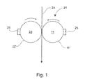
- Figure 1 shows an example in principle of a coating device 21 viewed from the side.
- the device 21 comprises two rotating application rolls 22, 11, which are adapted in a nip contact and between which the paper or board web 24 to be treated, in other words to be surface sized or coated, is adapted to travel.
- the direction of travel of the web 24 is indicated by an arrow, and the direction of travel of the rolls 22, 11 is also indicated by an arrow.
- a web 24 treatment substance such as a coating mixture or surface sizing agent, is spread onto the surfaces 22', 11' of the application rolls 22, 11 by means of coating applicators 25.
- the treatment substance layer is levelled and its thickness is adjusted by means of a doctor element such as a doctor blade or a rotating metering rod (reference number 15 in Figure 2 ).
- the doctored treatment substance layer is transferred from the application rolls 22, 11 onto both sides of the web 24 to be treated in a nip between the rolls 22, 11. If only one side of the web 24 is treated, the treatment substance is only spread onto one application roll 11.
- Figure 2 shows one example of a coating applicator 25 seen from the side.
- the coating applicator 25 is constructed to rest on the girder 12, and the application chamber 20 that is against the application roll 11 is formed by a space in the girder 12, which space is limited in the direction of rotation of the application roll 11 by a sealing blade 10 which comes first, i.e. on the inlet side, and by a metering rod 15 which is on the outlet side, i.e. latter in the direction of rotation.
- the sealing blade 10 is fastened to the girder 12 by means of a blade holder 17, and the metering rod 15 is fastened by means of a rod holder 14.
- the sealing blade 10 presses against the surface 11' of the application roll 11 and prevents the coating from flowing in an uncontrolled manner against the direction of rotation of the roll 11 and the access of air, which is carried with the rotating roll 11, into the application chamber 20.
- a metering rod 15 is placed at a distance from the sealing blade 10, which metering rod 15 is pressed against the application roll 11, but which metering rod 15 is suspended hydrodynamically at a distance from the surface 11' of the roll 11 by a film transferred onto the rotating roll 11. The thickness of the film transferred onto the surface 11' of the roll 11 is adjusted by changing the loading of the metering rod 15.
- the ends of the application chamber 20 are sealed in the case according to the embodiment by means of flexible seals 19, which limit the width of the area to be coated.
- the coating is fed into the application chamber 20 through nozzles 18 from a main tube 13 located inside the girder 12 and extending over the entire width of the coating applicator 25.
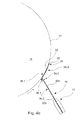
- Figure 3 presents one example of a sealing blade 10 viewed axially from the top, from its one end, which sealing blade 10 may be corresponding to the one installed in the coating applicator 25 in Figure 2 .
- the sealing blade 10 includes opposite elongated edges 30, 31 and a flat 32 between them.
- the flat 32 has two opposite sides, forming the flat surfaces 32a and 32b.
- the sealing blade 10 is adaptable, so that it may be replaced, to a blade holder 17 arranged in a coating applicator 25 of a coating device 21 and into contact with the moving surface 11'.
- the sealing blade 10 includes a fastening area 37 adapted on the side of the first elongated edge, the back edge 31, from which fastening area 37 the sealing blade 10 is adapted to be fastened to the blade holder 17.
- the fastening area 37 there may be for example die-cut fasteners, which ensure the fastening of the blade 10 to the holder 17.
- the second elongated edge, the front edge 30, which is opposite to this first edge 31 coming to the elongated holder 17, includes a tip 38, which is adaptable against the moving surface 11'.
- a contact surface 33 which may be arranged against the moving surface 11', is adapted in the sealing blade 10.
- Some examples of the contact surface 33 are presented in Figures 2 and 4a - 4c .
- the contact surface 33 is on the flat surface 32a of the sealing blade 10 on the side of the roll 11, in other words on a side different from the side of the application chamber 20.
- the contact surface 33 may be 5 - 15% of the width W of the sealing blade 10.
- the width W of the sealing blade refers to the distance between the elongated edges 30, 31 of the sealing blade 10, measured along the flat 32.
- the length L of the sealing blade 10 refers to the length of the sealing blade 10 in the cross direction of the machine.
- the length L of the sealing blade 10 may be several meters, as much as ten meters.
- the directions W and L are perpendicular to each other. It must be noted that in the figures the proportions of the sealing blade 10 and its parts are not necessarily actual proportions.
- the sealing blade 10 is, when installed in the blade holder 17, at a suitable angle with respect to the roll 11, and hence for example the lubrication of the tip 38 of the sealing blade 10 becomes sufficient and the tip 38 becomes less sharpened even otherwise, because part of the flat surface 32a is against the moving surface 11'.
- the contact surface 33 By arranging the contact surface 33 in the sealing blade 10, it can be brought into contact with the moving surface 11' more reliably over a larger area and especially over its flat 32 than merely by a connection over its elongated edge 30. Moreover, the contact surface 33 is in the sealing blade 10 already before it is installed in the blade holder 17, and it is not formed only when loading the blade 10 against the moving surface 11'. In other words, it can be said that initial tension has been removed from the blade 10 when it is installed in its blade holder 17. This makes the contact between the flat 32 of the blade 10 and the moving surface 11' very reliable, and at the same time the sharpening of the tip 38 of the blade 10 is reduced.
- flow openings 34, 34.1 - 34.3 may be adapted in the flat 32 of the sealing blade 10. Some examples of their locations have been presented in Figures 4a - 4c , where the openings are described in principle by the two-headed arrows running through the flat 32 of the blade 10. Most of the contact surface 33 may be adapted between the elongated edge 30 and the flow openings 34, 34.1 - 34.3 of the blade 10. The contact surface 33 and the flow openings 34, 34.1 - 34.3 are adapted in the sealing blade 10 so that when in contact with the moving surface 11', the flow openings 34, 34.1 - 34.3 adapted in the sealing blade 10 are at least partially separated from the moving surface 11'.
- the moving surface 11' does not block the flow openings 34, 34.1 - 34.3.
- This also ensures the functioning of the flow openings 34, 34.1 - 34.3 in all circumstances, in other words the access of air into the chamber 20 is prevented, the lubrication of the sealing blade 10 is ensured and the removal of overpressure from the chamber 20 is ensured.
- the location of the flow openings 34, 34.1 - 34.3 on the flat 32 of the blade 10 may be optimized for example close to a standardized contact surface 33 and hence the lubrication between for example the blade 10 and the moving surface 11' may be intensified.
- the contact surface 33 may be arranged in the sealing blade 10 for example so that the flat 32 of the sealing blade 10 is divided into two or more areas 35.1 - 35.3, of which the contact surface 33 is formed in at least one area 35.1, in other words on one side of the flat 32.
- the sealing blade 10 has been divided into two areas 35.1, 35.3, and the contact surface 33 is in the area 35.1.
- the contact surface 33 is in a planar area 35.1
- Figure 4b the contact surface 33 is in a curved area 35.1.
- the sealing blade 10 has been divided into three areas 35.1 - 35.3, and the contact surface 33 is again in the area 35.1, which is a planar area here, too.
- the areas 35.1 - 35.3 may be formed in several different ways.
- the flat 32 of the sealing blade 10 is divided into two or more areas 35.1 - 35.3 by means of one or more folds 36.1, 36.2.
- the sealing blade 10 has one fold 36.1
- the sealing blade 10 has two folds 36.1, 36.2.
- the fold 36.1, 36.2 may be a bevelled sharp fold or also a rounded fold. With two folds 36.1, 36.2, the angles of the folds do not need to be that great.
- the flat 32 of the sealing blade 10 may also be divided into two or more areas 35.1, 35.3 by means of one or more roundings 36.3. This is the case for example in Figure 4b .
- the folds 36.1, 36.2 and/or roundings 36.3, more generally the removal of the initial tension of the sealing blade 10, may be performed for example in the last stage of the manufacture of the sealing blade 10.
- Figures 4a present three different possibilities to arrange the flow openings 34.1 - 34.3 in the sealing blade 10. They can be for example in the same area 35.1 with the contact surface 33, in which case they are between the fold 36.1 and the contact surface 33. They can also be in the same area 35.3 where the sealing blade 10 is fastened to the holder 17. Moreover, they can also be at exactly the fold 36.1.
- the flow openings 34.3 are in the area 35.3
- the flow openings 34.1 are in the area 35.2.
- the distance D of the top edge of the flow openings 34 in other words that of the edge closest to the tip 38 of the blade 10, from the elongated edge 30 of the sealing blade 10, which edge 30 is equipped with the tip 38, may be for example 15 - 50 mm.
- the sealing blade 10 may be for example of spring steel type 1,4301, and its material thickness may be for example 0.254 - 0.381 mm and total width W for example 100 - 130 mm.
- the sealing blade 10 according to the invention is no longer a planar item known from prior art. Instead, its front edge 30 is deviated from the planar surface. The deviation may be accomplished for example by means of one or more angle folds in the longitudinal L direction of the blade 10. The folds may be located in the width W direction of the blade 10 at a distance of 5 - 15% from the tip 38 of the blade 10, which tip 38 is an edge 30 opposite to the edge 31 on the side of the blade holder 17.
- Another alternative presented for example in Figure 4b is to round the tip portion of the blade 10 in the area 33 in question to be curved in the same direction as the curvature of the roll surface 11'.
Landscapes
- Coating Apparatus (AREA)
Abstract
Description
- The invention relates to a sealing blade, which includes opposite elongated edges and between them a flat and which is adaptable to a blade holder arranged in a coating applicator of a coating device and into contact with a moving surface.
- The coating or surface sizing of paper or board may be performed for example using a film transfer coater. In it, the web to the treated runs through a nip located between two rolls. The coating mixture or sizing agent is spread using a specific coating applicator onto the surface of one roll or both rolls, from which surface it is transferred onto the surface of the web to be treated in the nip between the rolls. The thickness and profile of the sizing agent layer on the surface of the roll may be adjusted for example by means of a doctor blade or a rotating metering rod.
- The coating applicator may comprise an application chamber, which is limited in the direction of rotation of the roll by the doctor element and on the other hand by the front wall. In the lateral direction, the application chamber is limited by the side seals. The coating mixture or surface sizing agent is fed into the application chamber for example through a channel located in the girder of the coating applicator. The coating mixture is fed into the application chamber at such a great speed and pressure that a return flow is created in the gap between the front wall and the application roll, in other words a coating mixture flow or sizing agent flow in a direction opposite to the direction of rotation of the application roll is created. The purpose of the return flow is to prevent the penetration of air, which is on the surface of the application roll, into the application chamber. If air can enter the application chamber, places with no coating may be created in the web.
- It is well known that a sealing blade may be used as the front wall that closes the application chamber. The sealing blade may be pressed against the application roll so that no air escapes from between the blade and the application roll into the application chamber. There is no actual return flow from between the sealing blade and the application roll, but some coating mixture is led from the application chamber to the front of the blade through flow openings in the sealing blade. In this case, a pool of lubricant is formed in front of the sealing blade, which pool of lubricant prevents the friction occurring between the sealing blade and the application roll from damaging the roll or the sealing blade. If the pressure of the application chamber rises for example as a result of an excessive feeding of coating mixture, the force that presses the sealing blade against the application roll increases, whereby the sealing blade wears more rapidly and may damage the application roll or at least wear it.
- However, a drawback related to the prior art sealing blade is that the edge of the blade placed against the application roll becomes sharp in connection with the use of the blade. This causes occupational safety problems in the maintenance of the coating applicator. A sharpened sealing blade is dangerous to the maintenance personnel for example when the sealing blade, metering rod or the cradle of the metering rod is replaced. For the replacement of just the metering rod and its cradle, which replacement needs to be performed in some cases more frequently than the replacement of the sealing blade, it is not often customary to remove the sealing blade from the coating applicator, because this is troublesome to perform. What makes the removal of the sealing blade difficult is that it may be firmly stuck to its blade holder and would therefore require washing to facilitate the removal. A sealing blade which has become sharpened and which is also difficult to remove may cause incised wounds to employees and also damage to the surface of the application roll.
- Attempts in many different ways have been made to solve the problem related to the sealing blade becoming sharpened, but with little success. Since the holder of the sealing blade is fastened to the girder in a stationary manner, it is difficult to change the position of the holder. The sealing blade may also be lifted higher in the blade holder, but this does not always give the desired outcome, either. An attempt to enhance the lubrication that decreases the friction between the sealing blade and the application roll may be made by changing the feed pressure, but this is restricted by the seals that do not seal sufficiently well and by fouling problems. Moreover, it is not desirable to shift to a thinner sealing blade and a higher chamber pressure because of reasons such as increased leaks and splashes.
- One prior art sealing blade that can be mentioned is in FI patent number 103058. The sealing blade known from it is a planar item. Both flat surfaces of the blade are hence essentially similar planar surfaces, in other words the front edge and the back edge of the blade are in the same plane.
- The purpose of the present invention is to accomplish a sealing blade where the edge becomes less sharpened. The characteristics of the sealing blade according to the invention are presented in claim 1.
- In the invention, a contact surface, which may be arranged against a moving surface and which is 5 - 15% of the width of the sealing blade, is adapted in the sealing blade. As a result of the contact surface already adapted in the sealing blade in advance, the angle between the sealing blade and the moving surface decreases, the area of contact of the sealing blade with the moving surface increases, and the wear of the sealing blade decreases. In this way, also the flat surface of the sealing blade can be brought reliably into contact with the moving surface, the sharpening of the elongated edge of the sealing blade is reduced, and occupational safety related to the maintenance of the coating device is enhanced.
- According to one embodiment, flow openings may be included in the flat of the sealing blade. In this case, most of the contact surface is adapted between the elongated edge and the flow openings. This ensures the optimum functioning of the flow openings in all circumstances, and they do not settle against the moving surface.
- It is possible that the flat of the sealing blade is divided into two or more areas, and the contact surface is formed in at least one area. The division may be accomplished in different ways. Examples include folds or roundings to be made in the flat of the sealing blade. Several other advantages are also accomplished with the invention, such as longer service life of sealing blades, longer replacement interval of rolls, smaller quality variation of paper and board and higher production volume of paper and board, when sealing blades do not need to be replaced prematurely. The other additional advantages to be achieved with the invention are disclosed in the description of the invention, and the characteristics are disclosed in the claims.
- The invention, which is not restricted to the embodiments presented below, is described in more detail by making reference to the enclosed drawings, in which:
- Figure 1
- shows an example in principle of a coating device viewed from the side,
- Figure 2
- shows one example of a coating applicator seen from the side,
- Figure 3
- shows one example of a sealing blade viewed axially from the top, from one end of the sealing blade, and
- Figures 4a - 4c
- show on a rough level of principle various embodiments of the sealing blade and of how it settles against the application roll, viewed from the side.
-
Figure 1 shows an example in principle of acoating device 21 viewed from the side. In this case, thedevice 21 comprises tworotating application rolls board web 24 to be treated, in other words to be surface sized or coated, is adapted to travel. The direction of travel of theweb 24 is indicated by an arrow, and the direction of travel of therolls web 24 treatment substance, such as a coating mixture or surface sizing agent, is spread onto thesurfaces 22', 11' of theapplication rolls coating applicators 25. The treatment substance layer is levelled and its thickness is adjusted by means of a doctor element such as a doctor blade or a rotating metering rod (reference number 15 inFigure 2 ). The doctored treatment substance layer is transferred from theapplication rolls web 24 to be treated in a nip between therolls web 24 is treated, the treatment substance is only spread onto oneapplication roll 11. -
Figure 2 shows one example of acoating applicator 25 seen from the side. In this case, thecoating applicator 25 is constructed to rest on thegirder 12, and theapplication chamber 20 that is against theapplication roll 11 is formed by a space in thegirder 12, which space is limited in the direction of rotation of theapplication roll 11 by asealing blade 10 which comes first, i.e. on the inlet side, and by ametering rod 15 which is on the outlet side, i.e. latter in the direction of rotation. The sealingblade 10 is fastened to thegirder 12 by means of ablade holder 17, and themetering rod 15 is fastened by means of arod holder 14. - The sealing
blade 10 presses against the surface 11' of theapplication roll 11 and prevents the coating from flowing in an uncontrolled manner against the direction of rotation of theroll 11 and the access of air, which is carried with the rotatingroll 11, into theapplication chamber 20. Ametering rod 15 is placed at a distance from thesealing blade 10, whichmetering rod 15 is pressed against theapplication roll 11, but whichmetering rod 15 is suspended hydrodynamically at a distance from the surface 11' of theroll 11 by a film transferred onto the rotatingroll 11. The thickness of the film transferred onto the surface 11' of theroll 11 is adjusted by changing the loading of themetering rod 15. The distance between the sealingblade 10 and themetering rod 15 forms an application distance, and theapplication chamber 20 is hence limited by thegirder 12, sealingblade 10,metering rod 15 andapplication roll 11. The ends of theapplication chamber 20 are sealed in the case according to the embodiment by means offlexible seals 19, which limit the width of the area to be coated. The coating is fed into theapplication chamber 20 throughnozzles 18 from amain tube 13 located inside thegirder 12 and extending over the entire width of thecoating applicator 25. -
Figure 3 presents one example of asealing blade 10 viewed axially from the top, from its one end, which sealingblade 10 may be corresponding to the one installed in thecoating applicator 25 inFigure 2 . Thesealing blade 10 includes opposite elongatededges flat surfaces flat surface 32a of the flat 32 on the side of theroll 11 and theflat surface 32b on the side of theapplication chamber 20. Of these flat surfaces,Figure 3 shows theflat surface 32b on the side of theapplication chamber 20. - The
sealing blade 10 is adaptable, so that it may be replaced, to ablade holder 17 arranged in acoating applicator 25 of acoating device 21 and into contact with the moving surface 11'. For these, thesealing blade 10 includes afastening area 37 adapted on the side of the first elongated edge, theback edge 31, from whichfastening area 37 thesealing blade 10 is adapted to be fastened to theblade holder 17. In thefastening area 37, there may be for example die-cut fasteners, which ensure the fastening of theblade 10 to theholder 17. The second elongated edge, thefront edge 30, which is opposite to thisfirst edge 31 coming to theelongated holder 17, includes atip 38, which is adaptable against the moving surface 11'. - A
contact surface 33, which may be arranged against the moving surface 11', is adapted in thesealing blade 10. Some examples of thecontact surface 33 are presented inFigures 2 and4a - 4c . Thecontact surface 33 is on theflat surface 32a of thesealing blade 10 on the side of theroll 11, in other words on a side different from the side of theapplication chamber 20. Thecontact surface 33 may be 5 - 15% of the width W of thesealing blade 10. In this connection, the width W of the sealing blade refers to the distance between theelongated edges sealing blade 10, measured along the flat 32. Correspondingly, the length L of thesealing blade 10 refers to the length of thesealing blade 10 in the cross direction of the machine. The length L of thesealing blade 10 may be several meters, as much as ten meters. The directions W and L are perpendicular to each other. It must be noted that in the figures the proportions of thesealing blade 10 and its parts are not necessarily actual proportions. As a result of thecontact surface 33 arranged in thesealing blade 10 as early as during its manufacture, thesealing blade 10 is, when installed in theblade holder 17, at a suitable angle with respect to theroll 11, and hence for example the lubrication of thetip 38 of thesealing blade 10 becomes sufficient and thetip 38 becomes less sharpened even otherwise, because part of theflat surface 32a is against the moving surface 11'. - By arranging the
contact surface 33 in thesealing blade 10, it can be brought into contact with the moving surface 11' more reliably over a larger area and especially over its flat 32 than merely by a connection over itselongated edge 30. Moreover, thecontact surface 33 is in thesealing blade 10 already before it is installed in theblade holder 17, and it is not formed only when loading theblade 10 against the moving surface 11'. In other words, it can be said that initial tension has been removed from theblade 10 when it is installed in itsblade holder 17. This makes the contact between the flat 32 of theblade 10 and the moving surface 11' very reliable, and at the same time the sharpening of thetip 38 of theblade 10 is reduced. - According to one embodiment,
flow openings 34, 34.1 - 34.3 may be adapted in the flat 32 of thesealing blade 10. Some examples of their locations have been presented inFigures 4a - 4c , where the openings are described in principle by the two-headed arrows running through the flat 32 of theblade 10. Most of thecontact surface 33 may be adapted between theelongated edge 30 and theflow openings 34, 34.1 - 34.3 of theblade 10. Thecontact surface 33 and theflow openings 34, 34.1 - 34.3 are adapted in thesealing blade 10 so that when in contact with the moving surface 11', theflow openings 34, 34.1 - 34.3 adapted in thesealing blade 10 are at least partially separated from the moving surface 11'. In this case, the moving surface 11' does not block theflow openings 34, 34.1 - 34.3. This also ensures the functioning of theflow openings 34, 34.1 - 34.3 in all circumstances, in other words the access of air into thechamber 20 is prevented, the lubrication of thesealing blade 10 is ensured and the removal of overpressure from thechamber 20 is ensured. As a result of the invention, it is even possible to improve the impacts achieved with the flow opening 34, 34.1 - 34.3. The location of theflow openings 34, 34.1 - 34.3 on the flat 32 of theblade 10 may be optimized for example close to astandardized contact surface 33 and hence the lubrication between for example theblade 10 and the moving surface 11' may be intensified. - According to one embodiment, the
contact surface 33 may be arranged in thesealing blade 10 for example so that the flat 32 of thesealing blade 10 is divided into two or more areas 35.1 - 35.3, of which thecontact surface 33 is formed in at least one area 35.1, in other words on one side of the flat 32. InFigures 4a and4b , thesealing blade 10 has been divided into two areas 35.1, 35.3, and thecontact surface 33 is in the area 35.1. InFigure 4a , thecontact surface 33 is in a planar area 35.1, and inFigure 4b thecontact surface 33 is in a curved area 35.1. Correspondingly, inFigure 4c thesealing blade 10 has been divided into three areas 35.1 - 35.3, and thecontact surface 33 is again in the area 35.1, which is a planar area here, too. - According to the embodiments presented in
Figures 4a - 4c , the areas 35.1 - 35.3 may be formed in several different ways. According to a first embodiment, the flat 32 of thesealing blade 10 is divided into two or more areas 35.1 - 35.3 by means of one or more folds 36.1, 36.2. InFigures 4a and4b , thesealing blade 10 has one fold 36.1, and inFigure 4c , thesealing blade 10 has two folds 36.1, 36.2. The fold 36.1, 36.2 may be a bevelled sharp fold or also a rounded fold. With two folds 36.1, 36.2, the angles of the folds do not need to be that great. The flat 32 of thesealing blade 10 may also be divided into two or more areas 35.1, 35.3 by means of one or more roundings 36.3. This is the case for example inFigure 4b . The folds 36.1, 36.2 and/or roundings 36.3, more generally the removal of the initial tension of thesealing blade 10, may be performed for example in the last stage of the manufacture of thesealing blade 10. -
Figures 4a present three different possibilities to arrange the flow openings 34.1 - 34.3 in thesealing blade 10. They can be for example in the same area 35.1 with thecontact surface 33, in which case they are between the fold 36.1 and thecontact surface 33. They can also be in the same area 35.3 where thesealing blade 10 is fastened to theholder 17. Moreover, they can also be at exactly the fold 36.1. In the embodiment ofFigure 4b , the flow openings 34.3 are in the area 35.3, and inFigure 4c the flow openings 34.1 are in the area 35.2. - The distance D of the top edge of the
flow openings 34, in other words that of the edge closest to thetip 38 of theblade 10, from theelongated edge 30 of thesealing blade 10, whichedge 30 is equipped with thetip 38, may be for example 15 - 50 mm. Thesealing blade 10 may be for example of spring steel type 1,4301, and its material thickness may be for example 0.254 - 0.381 mm and total width W for example 100 - 130 mm. - As presented above, the
sealing blade 10 according to the invention is no longer a planar item known from prior art. Instead, itsfront edge 30 is deviated from the planar surface. The deviation may be accomplished for example by means of one or more angle folds in the longitudinal L direction of theblade 10. The folds may be located in the width W direction of theblade 10 at a distance of 5 - 15% from thetip 38 of theblade 10, which tip 38 is anedge 30 opposite to theedge 31 on the side of theblade holder 17. Another alternative presented for example inFigure 4b is to round the tip portion of theblade 10 in thearea 33 in question to be curved in the same direction as the curvature of the roll surface 11'. - It is to be understood that the above description and the related figures are only intended to illustrate the present invention. The invention is hence not only restricted to the above-presented embodiments or the embodiments defined in the claims, but several different variations and adaptations of the invention will also be obvious to a professional in the field, which variations and adaptations are possible within the inventive idea defined by the enclosed claims.
Claims (9)
- A sealing blade, which includes opposite elongated edges (30, 31) and between them a flat (32) and which is adaptable to a blade holder (17) arranged in a coating applicator (25) of a coating device (21) and into contact with a moving surface (11'), characterized in that a contact surface (33), which may be arranged against the moving surface (11') and which is 5 - 15% of the width (W) of the sealing blade (10) , is adapted in the sealing blade (10) .
- A sealing blade according to claim 1, where flow openings (34, 34.1 - 34.3) are adapted on the flat (32) of the sealing blade, characterized in that most of the contact surface (33) is adapted between the elongated edge (30) and the flow openings (34, 34.1 - 34.3).
- A sealing blade according to claim 1 or 2, where flow openings (34, 34.1 - 34.3) are adapted on the flat (32) of the sealing blade, characterized in that the contact surface (33) is adapted in the sealing blade (10) so that when in contact with the moving surface (11'), the flow openings (34, 34.1 - 34.3) adapted in the sealing blade (10) are at least partially separated from the moving surface (11').
- A sealing blade according to any one of claims 1 - 3, characterized in that the flat (32) of the sealing blade (10) is divided into two or more areas (35.1 - 35.3), from which the contact surface (33) is formed in at least one area (35.1).
- A sealing blade according to any one of claims 1 - 4, characterized in that the flat (32) of the sealing blade (10) is divided into two or more areas (35.1 - 35.3) by means of one or more folds (36.1, 36.2).
- A sealing blade according to any one of claims 1 - 5, characterized in that the flat (32) of the sealing blade (10) is divided into two or more areas (35.1, 35.3) by means of one or more roundings (36.3).
- A sealing blade according to any one of claims 2 - 6, characterized in that the distance (D) of the top edge of the flow openings (34) from the elongated edge (30) of the sealing blade (10) is 15 - 50 mm.
- A sealing blade according to any one of claims 1 - 7, characterized in that the sealing blade (10) includes:- a fastening area (37) adapted on the side of a first elongated edge (31), from which fastening area (37) the sealing blade (10) is adapted to be fastened to said blade holder (17),- a second elongated edge (30), which is opposite to the first elongated edge (31),- flat surfaces (32a, 32b) located on the opposite sides of the sealing blade (10) between the elongated edges (30, 31), to which flat surface said contact surface (33) is adapted on one side.
- A sealing blade according to claim 8, characterized in that a tip (38), which is adaptable against the moving surface (11'), is adapted on one elongated edge (30) of the sealing blade (10).
Applications Claiming Priority (1)
| Application Number | Priority Date | Filing Date | Title |
|---|---|---|---|
| FI20146006A FI126700B (en) | 2014-11-18 | 2014-11-18 | sealing Sheet |
Publications (2)
| Publication Number | Publication Date |
|---|---|
| EP3023163A1 true EP3023163A1 (en) | 2016-05-25 |
| EP3023163B1 EP3023163B1 (en) | 2020-05-13 |
Family
ID=54540954
Family Applications (1)
| Application Number | Title | Priority Date | Filing Date |
|---|---|---|---|
| EP15194249.7A Active EP3023163B1 (en) | 2014-11-18 | 2015-11-12 | Sealing blade |
Country Status (4)
| Country | Link |
|---|---|
| EP (1) | EP3023163B1 (en) |
| CN (1) | CN105603822B (en) |
| ES (1) | ES2811278T3 (en) |
| FI (1) | FI126700B (en) |
Cited By (1)
| Publication number | Priority date | Publication date | Assignee | Title |
|---|---|---|---|---|
| EP3842591A1 (en) | 2019-12-23 | 2021-06-30 | Andritz Küsters GmbH | Device for applying an applied medium |
Citations (7)
| Publication number | Priority date | Publication date | Assignee | Title |
|---|---|---|---|---|
| US4839201A (en) * | 1987-12-03 | 1989-06-13 | Valmet Paper Machinery Inc. | Method and apparatus for applying coating liquid to a moving base |
| FI103058B (en) | 1997-09-17 | 1999-04-15 | Valmet Corp | Apparatus for feeding treatment substance into an application chamber with an application device used in the treatment of paper or cardboard, as well as a method for even distribution of the substance in the chamber |
| US5902401A (en) * | 1997-07-09 | 1999-05-11 | Pevifibe Papers Inc. | Coater head |
| US6024797A (en) * | 1998-03-30 | 2000-02-15 | Beloit Technologies, Inc. | Method and apparatus for controlling coat-weight profile |
| US6579368B1 (en) * | 1999-07-22 | 2003-06-17 | Voith Sulzer Papiertechnik Patent Gmbh | Apparatus for the application of a liquid or pasty medium to a moving fiber web |
| WO2004070113A1 (en) * | 2003-02-10 | 2004-08-19 | Metso Paper, Inc. | Applicator apparatus of a film-transfer coater and coating method |
| EP1733802A1 (en) * | 2005-06-15 | 2006-12-20 | PAMA Papiermaschinen GmbH | Device for applying a liquid or pasty suspension on paper or board webs |
Family Cites Families (7)
| Publication number | Priority date | Publication date | Assignee | Title |
|---|---|---|---|---|
| US5249547A (en) * | 1990-03-29 | 1993-10-05 | Kyokutosanki Co., Ltd. | Manually operated sizing machine |
| JP3453716B2 (en) * | 1995-03-22 | 2003-10-06 | 三菱製紙株式会社 | Manufacturing method of coated paper for printing |
| BE1011561A5 (en) * | 1997-11-21 | 1999-10-05 | Volder Laurent De | METHOD AND APPARATUS FOR INKINKING AN ENGRAVED CLICHEBATE FROM AN INK RESERVOIR. |
| JP3965416B1 (en) * | 2006-06-16 | 2007-08-29 | 株式会社堅牢防水化学 | Doctor blade used for resin processing on fabric and resin processing method using the same |
| JP5568978B2 (en) * | 2009-12-17 | 2014-08-13 | 凸版印刷株式会社 | Gravure coating device and liquid removal device |
| CN102430499A (en) * | 2010-09-29 | 2012-05-02 | 竞陆电子(昆山)有限公司 | Coating scraper |
| CN203170534U (en) * | 2013-03-25 | 2013-09-04 | 无锡侨颂特种纸有限公司 | Coating scraper |
-
2014
- 2014-11-18 FI FI20146006A patent/FI126700B/en active IP Right Grant
-
2015
- 2015-11-12 EP EP15194249.7A patent/EP3023163B1/en active Active
- 2015-11-12 ES ES15194249T patent/ES2811278T3/en active Active
- 2015-11-18 CN CN201510794912.5A patent/CN105603822B/en active Active
Patent Citations (7)
| Publication number | Priority date | Publication date | Assignee | Title |
|---|---|---|---|---|
| US4839201A (en) * | 1987-12-03 | 1989-06-13 | Valmet Paper Machinery Inc. | Method and apparatus for applying coating liquid to a moving base |
| US5902401A (en) * | 1997-07-09 | 1999-05-11 | Pevifibe Papers Inc. | Coater head |
| FI103058B (en) | 1997-09-17 | 1999-04-15 | Valmet Corp | Apparatus for feeding treatment substance into an application chamber with an application device used in the treatment of paper or cardboard, as well as a method for even distribution of the substance in the chamber |
| US6024797A (en) * | 1998-03-30 | 2000-02-15 | Beloit Technologies, Inc. | Method and apparatus for controlling coat-weight profile |
| US6579368B1 (en) * | 1999-07-22 | 2003-06-17 | Voith Sulzer Papiertechnik Patent Gmbh | Apparatus for the application of a liquid or pasty medium to a moving fiber web |
| WO2004070113A1 (en) * | 2003-02-10 | 2004-08-19 | Metso Paper, Inc. | Applicator apparatus of a film-transfer coater and coating method |
| EP1733802A1 (en) * | 2005-06-15 | 2006-12-20 | PAMA Papiermaschinen GmbH | Device for applying a liquid or pasty suspension on paper or board webs |
Cited By (2)
| Publication number | Priority date | Publication date | Assignee | Title |
|---|---|---|---|---|
| EP3842591A1 (en) | 2019-12-23 | 2021-06-30 | Andritz Küsters GmbH | Device for applying an applied medium |
| US11718961B2 (en) | 2019-12-23 | 2023-08-08 | Andritz Küsters Gmbh | Device for applying a treatment substance |
Also Published As
| Publication number | Publication date |
|---|---|
| FI126700B (en) | 2017-04-13 |
| CN105603822B (en) | 2018-04-10 |
| CN105603822A (en) | 2016-05-25 |
| ES2811278T3 (en) | 2021-03-11 |
| EP3023163B1 (en) | 2020-05-13 |
| FI20146006A7 (en) | 2016-05-19 |
Similar Documents
| Publication | Publication Date | Title |
|---|---|---|
| US4182472A (en) | Contactless turning guide for running webs | |
| US20150191872A1 (en) | Sealing strip | |
| US8434338B2 (en) | Device for cooling a metal strip | |
| EP3023163B1 (en) | Sealing blade | |
| US9925555B2 (en) | Folded sealing blade for a coating applicator | |
| US5778559A (en) | Device and process for moistening a running material web | |
| CN104641038A (en) | Suction roll for a machine for producing and/or processing a paper, cardboard or tissue web | |
| US10279286B2 (en) | Method for constructing a vacuum belt filter device and vacuum belt filter device | |
| US3356067A (en) | Doctor blades having relieved ends | |
| US5628250A (en) | Chamber doctor blade assembly | |
| WO2015169475A1 (en) | Strip deflector and roll assembly | |
| CN104583488A (en) | Sealing device and roll with a sealing device | |
| EP2045021A1 (en) | Die lip for strip coating | |
| NZ207311A (en) | Coating a running paper web:web fed upwards through applicator containing coating substance to smoothing nip | |
| EP3129158B1 (en) | Method and apparatus for coating a continuous moving metal strip and installation for continuous rolling of metal pieces | |
| FI110170B (en) | Teräpäällyskone | |
| US11679524B2 (en) | Perforator lubrication system | |
| EP3221513B1 (en) | Lubricant applicator and method for lubricating a backing drum and apparatus | |
| KR100291959B1 (en) | Short dwell coating device | |
| US5919338A (en) | Cleaning apparatus for a papermachine forming wire | |
| US10724177B2 (en) | Systems and methods for providing fluid extraction vacuum box covers with integral lubrication | |
| AT13710U1 (en) | Pressing device for a machine for producing a fibrous web | |
| DE19827030A1 (en) | Application device | |
| EP1475477A2 (en) | Apparatus for applying directly a fluid or pasty coating onto a moving web | |
| DE102011090043A1 (en) | Strip material i.e. punched strip, oiling device for reducing wear of e.g. top knife in punching and/or shaping machine, has pipe coating lateral surface of rollers with oil, and doctor blade adjusting thickness of oil layer on rollers |
Legal Events
| Date | Code | Title | Description |
|---|---|---|---|
| AK | Designated contracting states |
Kind code of ref document: A1 Designated state(s): AL AT BE BG CH CY CZ DE DK EE ES FI FR GB GR HR HU IE IS IT LI LT LU LV MC MK MT NL NO PL PT RO RS SE SI SK SM TR |
|
| AX | Request for extension of the european patent |
Extension state: BA ME |
|
| PUAI | Public reference made under article 153(3) epc to a published international application that has entered the european phase |
Free format text: ORIGINAL CODE: 0009012 |
|
| STAA | Information on the status of an ep patent application or granted ep patent |
Free format text: STATUS: REQUEST FOR EXAMINATION WAS MADE |
|
| 17P | Request for examination filed |
Effective date: 20161125 |
|
| RBV | Designated contracting states (corrected) |
Designated state(s): AL AT BE BG CH CY CZ DE DK EE ES FI FR GB GR HR HU IE IS IT LI LT LU LV MC MK MT NL NO PL PT RO RS SE SI SK SM TR |
|
| STAA | Information on the status of an ep patent application or granted ep patent |
Free format text: STATUS: EXAMINATION IS IN PROGRESS |
|
| 17Q | First examination report despatched |
Effective date: 20190402 |
|
| GRAP | Despatch of communication of intention to grant a patent |
Free format text: ORIGINAL CODE: EPIDOSNIGR1 |
|
| STAA | Information on the status of an ep patent application or granted ep patent |
Free format text: STATUS: GRANT OF PATENT IS INTENDED |
|
| INTG | Intention to grant announced |
Effective date: 20200122 |
|
| GRAS | Grant fee paid |
Free format text: ORIGINAL CODE: EPIDOSNIGR3 |
|
| GRAA | (expected) grant |
Free format text: ORIGINAL CODE: 0009210 |
|
| STAA | Information on the status of an ep patent application or granted ep patent |
Free format text: STATUS: THE PATENT HAS BEEN GRANTED |
|
| AK | Designated contracting states |
Kind code of ref document: B1 Designated state(s): AL AT BE BG CH CY CZ DE DK EE ES FI FR GB GR HR HU IE IS IT LI LT LU LV MC MK MT NL NO PL PT RO RS SE SI SK SM TR |
|
| REG | Reference to a national code |
Ref country code: GB Ref legal event code: FG4D |
|
| REG | Reference to a national code |
Ref country code: CH Ref legal event code: EP |
|
| REG | Reference to a national code |
Ref country code: DE Ref legal event code: R096 Ref document number: 602015052665 Country of ref document: DE |
|
| REG | Reference to a national code |
Ref country code: AT Ref legal event code: REF Ref document number: 1269564 Country of ref document: AT Kind code of ref document: T Effective date: 20200615 |
|
| REG | Reference to a national code |
Ref country code: CH Ref legal event code: NV Representative=s name: VALIPAT S.A. C/O BOVARD SA NEUCHATEL, CH |
|
| REG | Reference to a national code |
Ref country code: SE Ref legal event code: TRGR |
|
| REG | Reference to a national code |
Ref country code: LT Ref legal event code: MG4D |
|
| REG | Reference to a national code |
Ref country code: NL Ref legal event code: MP Effective date: 20200513 |
|
| PG25 | Lapsed in a contracting state [announced via postgrant information from national office to epo] |
Ref country code: IS Free format text: LAPSE BECAUSE OF FAILURE TO SUBMIT A TRANSLATION OF THE DESCRIPTION OR TO PAY THE FEE WITHIN THE PRESCRIBED TIME-LIMIT Effective date: 20200913 Ref country code: PT Free format text: LAPSE BECAUSE OF FAILURE TO SUBMIT A TRANSLATION OF THE DESCRIPTION OR TO PAY THE FEE WITHIN THE PRESCRIBED TIME-LIMIT Effective date: 20200914 Ref country code: LT Free format text: LAPSE BECAUSE OF FAILURE TO SUBMIT A TRANSLATION OF THE DESCRIPTION OR TO PAY THE FEE WITHIN THE PRESCRIBED TIME-LIMIT Effective date: 20200513 Ref country code: NO Free format text: LAPSE BECAUSE OF FAILURE TO SUBMIT A TRANSLATION OF THE DESCRIPTION OR TO PAY THE FEE WITHIN THE PRESCRIBED TIME-LIMIT Effective date: 20200813 Ref country code: FI Free format text: LAPSE BECAUSE OF FAILURE TO SUBMIT A TRANSLATION OF THE DESCRIPTION OR TO PAY THE FEE WITHIN THE PRESCRIBED TIME-LIMIT Effective date: 20200513 Ref country code: GR Free format text: LAPSE BECAUSE OF FAILURE TO SUBMIT A TRANSLATION OF THE DESCRIPTION OR TO PAY THE FEE WITHIN THE PRESCRIBED TIME-LIMIT Effective date: 20200814 |
|
| PG25 | Lapsed in a contracting state [announced via postgrant information from national office to epo] |
Ref country code: BG Free format text: LAPSE BECAUSE OF FAILURE TO SUBMIT A TRANSLATION OF THE DESCRIPTION OR TO PAY THE FEE WITHIN THE PRESCRIBED TIME-LIMIT Effective date: 20200813 Ref country code: RS Free format text: LAPSE BECAUSE OF FAILURE TO SUBMIT A TRANSLATION OF THE DESCRIPTION OR TO PAY THE FEE WITHIN THE PRESCRIBED TIME-LIMIT Effective date: 20200513 Ref country code: HR Free format text: LAPSE BECAUSE OF FAILURE TO SUBMIT A TRANSLATION OF THE DESCRIPTION OR TO PAY THE FEE WITHIN THE PRESCRIBED TIME-LIMIT Effective date: 20200513 Ref country code: LV Free format text: LAPSE BECAUSE OF FAILURE TO SUBMIT A TRANSLATION OF THE DESCRIPTION OR TO PAY THE FEE WITHIN THE PRESCRIBED TIME-LIMIT Effective date: 20200513 |
|
| PG25 | Lapsed in a contracting state [announced via postgrant information from national office to epo] |
Ref country code: AL Free format text: LAPSE BECAUSE OF FAILURE TO SUBMIT A TRANSLATION OF THE DESCRIPTION OR TO PAY THE FEE WITHIN THE PRESCRIBED TIME-LIMIT Effective date: 20200513 Ref country code: NL Free format text: LAPSE BECAUSE OF FAILURE TO SUBMIT A TRANSLATION OF THE DESCRIPTION OR TO PAY THE FEE WITHIN THE PRESCRIBED TIME-LIMIT Effective date: 20200513 |
|
| PG25 | Lapsed in a contracting state [announced via postgrant information from national office to epo] |
Ref country code: SM Free format text: LAPSE BECAUSE OF FAILURE TO SUBMIT A TRANSLATION OF THE DESCRIPTION OR TO PAY THE FEE WITHIN THE PRESCRIBED TIME-LIMIT Effective date: 20200513 Ref country code: RO Free format text: LAPSE BECAUSE OF FAILURE TO SUBMIT A TRANSLATION OF THE DESCRIPTION OR TO PAY THE FEE WITHIN THE PRESCRIBED TIME-LIMIT Effective date: 20200513 Ref country code: DK Free format text: LAPSE BECAUSE OF FAILURE TO SUBMIT A TRANSLATION OF THE DESCRIPTION OR TO PAY THE FEE WITHIN THE PRESCRIBED TIME-LIMIT Effective date: 20200513 Ref country code: EE Free format text: LAPSE BECAUSE OF FAILURE TO SUBMIT A TRANSLATION OF THE DESCRIPTION OR TO PAY THE FEE WITHIN THE PRESCRIBED TIME-LIMIT Effective date: 20200513 Ref country code: CZ Free format text: LAPSE BECAUSE OF FAILURE TO SUBMIT A TRANSLATION OF THE DESCRIPTION OR TO PAY THE FEE WITHIN THE PRESCRIBED TIME-LIMIT Effective date: 20200513 |
|
| REG | Reference to a national code |
Ref country code: DE Ref legal event code: R097 Ref document number: 602015052665 Country of ref document: DE |
|
| PG25 | Lapsed in a contracting state [announced via postgrant information from national office to epo] |
Ref country code: PL Free format text: LAPSE BECAUSE OF FAILURE TO SUBMIT A TRANSLATION OF THE DESCRIPTION OR TO PAY THE FEE WITHIN THE PRESCRIBED TIME-LIMIT Effective date: 20200513 Ref country code: SK Free format text: LAPSE BECAUSE OF FAILURE TO SUBMIT A TRANSLATION OF THE DESCRIPTION OR TO PAY THE FEE WITHIN THE PRESCRIBED TIME-LIMIT Effective date: 20200513 |
|
| REG | Reference to a national code |
Ref country code: ES Ref legal event code: FG2A Ref document number: 2811278 Country of ref document: ES Kind code of ref document: T3 Effective date: 20210311 |
|
| PLBE | No opposition filed within time limit |
Free format text: ORIGINAL CODE: 0009261 |
|
| STAA | Information on the status of an ep patent application or granted ep patent |
Free format text: STATUS: NO OPPOSITION FILED WITHIN TIME LIMIT |
|
| 26N | No opposition filed |
Effective date: 20210216 |
|
| PG25 | Lapsed in a contracting state [announced via postgrant information from national office to epo] |
Ref country code: SI Free format text: LAPSE BECAUSE OF FAILURE TO SUBMIT A TRANSLATION OF THE DESCRIPTION OR TO PAY THE FEE WITHIN THE PRESCRIBED TIME-LIMIT Effective date: 20200513 |
|
| PG25 | Lapsed in a contracting state [announced via postgrant information from national office to epo] |
Ref country code: MC Free format text: LAPSE BECAUSE OF FAILURE TO SUBMIT A TRANSLATION OF THE DESCRIPTION OR TO PAY THE FEE WITHIN THE PRESCRIBED TIME-LIMIT Effective date: 20200513 |
|
| PG25 | Lapsed in a contracting state [announced via postgrant information from national office to epo] |
Ref country code: LU Free format text: LAPSE BECAUSE OF NON-PAYMENT OF DUE FEES Effective date: 20201112 |
|
| REG | Reference to a national code |
Ref country code: BE Ref legal event code: MM Effective date: 20201130 |
|
| PG25 | Lapsed in a contracting state [announced via postgrant information from national office to epo] |
Ref country code: IE Free format text: LAPSE BECAUSE OF NON-PAYMENT OF DUE FEES Effective date: 20201112 |
|
| REG | Reference to a national code |
Ref country code: AT Ref legal event code: UEP Ref document number: 1269564 Country of ref document: AT Kind code of ref document: T Effective date: 20200513 |
|
| PG25 | Lapsed in a contracting state [announced via postgrant information from national office to epo] |
Ref country code: TR Free format text: LAPSE BECAUSE OF FAILURE TO SUBMIT A TRANSLATION OF THE DESCRIPTION OR TO PAY THE FEE WITHIN THE PRESCRIBED TIME-LIMIT Effective date: 20200513 Ref country code: MT Free format text: LAPSE BECAUSE OF FAILURE TO SUBMIT A TRANSLATION OF THE DESCRIPTION OR TO PAY THE FEE WITHIN THE PRESCRIBED TIME-LIMIT Effective date: 20200513 Ref country code: CY Free format text: LAPSE BECAUSE OF FAILURE TO SUBMIT A TRANSLATION OF THE DESCRIPTION OR TO PAY THE FEE WITHIN THE PRESCRIBED TIME-LIMIT Effective date: 20200513 |
|
| PG25 | Lapsed in a contracting state [announced via postgrant information from national office to epo] |
Ref country code: MK Free format text: LAPSE BECAUSE OF FAILURE TO SUBMIT A TRANSLATION OF THE DESCRIPTION OR TO PAY THE FEE WITHIN THE PRESCRIBED TIME-LIMIT Effective date: 20200513 |
|
| PG25 | Lapsed in a contracting state [announced via postgrant information from national office to epo] |
Ref country code: BE Free format text: LAPSE BECAUSE OF NON-PAYMENT OF DUE FEES Effective date: 20201130 |
|
| P01 | Opt-out of the competence of the unified patent court (upc) registered |
Effective date: 20230602 |
|
| REG | Reference to a national code |
Ref country code: CH Ref legal event code: U11 Free format text: ST27 STATUS EVENT CODE: U-0-0-U10-U11 (AS PROVIDED BY THE NATIONAL OFFICE) Effective date: 20251201 |
|
| PGFP | Annual fee paid to national office [announced via postgrant information from national office to epo] |
Ref country code: DE Payment date: 20251119 Year of fee payment: 11 |
|
| PGFP | Annual fee paid to national office [announced via postgrant information from national office to epo] |
Ref country code: GB Payment date: 20251121 Year of fee payment: 11 |
|
| PGFP | Annual fee paid to national office [announced via postgrant information from national office to epo] |
Ref country code: AT Payment date: 20251120 Year of fee payment: 11 |
|
| PGFP | Annual fee paid to national office [announced via postgrant information from national office to epo] |
Ref country code: IT Payment date: 20251125 Year of fee payment: 11 |
|
| PGFP | Annual fee paid to national office [announced via postgrant information from national office to epo] |
Ref country code: FR Payment date: 20251125 Year of fee payment: 11 |
|
| PGFP | Annual fee paid to national office [announced via postgrant information from national office to epo] |
Ref country code: CH Payment date: 20251201 Year of fee payment: 11 Ref country code: SE Payment date: 20251119 Year of fee payment: 11 |
|
| PGFP | Annual fee paid to national office [announced via postgrant information from national office to epo] |
Ref country code: ES Payment date: 20251229 Year of fee payment: 11 |