EP3025834B1 - Dispositif de guidage - Google Patents
Dispositif de guidage Download PDFInfo
- Publication number
- EP3025834B1 EP3025834B1 EP15196022.6A EP15196022A EP3025834B1 EP 3025834 B1 EP3025834 B1 EP 3025834B1 EP 15196022 A EP15196022 A EP 15196022A EP 3025834 B1 EP3025834 B1 EP 3025834B1
- Authority
- EP
- European Patent Office
- Prior art keywords
- guiding
- conveying direction
- lateral
- vertical
- guiding device
- Prior art date
- Legal status (The legal status is an assumption and is not a legal conclusion. Google has not performed a legal analysis and makes no representation as to the accuracy of the status listed.)
- Active
Links
Images





Classifications
-
- B—PERFORMING OPERATIONS; TRANSPORTING
- B27—WORKING OR PRESERVING WOOD OR SIMILAR MATERIAL; NAILING OR STAPLING MACHINES IN GENERAL
- B27M—WORKING OF WOOD NOT PROVIDED FOR IN SUBCLASSES B27B - B27L; MANUFACTURE OF SPECIFIC WOODEN ARTICLES
- B27M1/00—Working of wood not provided for in subclasses B27B - B27L, e.g. by stretching
- B27M1/08—Working of wood not provided for in subclasses B27B - B27L, e.g. by stretching by multi-step processes
-
- B—PERFORMING OPERATIONS; TRANSPORTING
- B27—WORKING OR PRESERVING WOOD OR SIMILAR MATERIAL; NAILING OR STAPLING MACHINES IN GENERAL
- B27C—PLANING, DRILLING, MILLING, TURNING OR UNIVERSAL MACHINES FOR WOOD OR SIMILAR MATERIAL
- B27C5/00—Machines designed for producing special profiles or shaped work, e.g. by rotary cutters; Equipment therefor
- B27C5/02—Machines with table
- B27C5/04—Guide fences for work
-
- B—PERFORMING OPERATIONS; TRANSPORTING
- B27—WORKING OR PRESERVING WOOD OR SIMILAR MATERIAL; NAILING OR STAPLING MACHINES IN GENERAL
- B27C—PLANING, DRILLING, MILLING, TURNING OR UNIVERSAL MACHINES FOR WOOD OR SIMILAR MATERIAL
- B27C5/00—Machines designed for producing special profiles or shaped work, e.g. by rotary cutters; Equipment therefor
- B27C5/02—Machines with table
- B27C5/06—Arrangements for clamping or feeding work
Definitions
- the invention relates to a guide device for a workpiece and a woodworking machine with the features in the preamble of the independent claims.
- Such a guide device and such a processing machine go, for example, from EP 0 906 815 A2 emerged.
- a woodworking machine with a one-dimensionally adjustable guide device is known from practice.
- the range of variants of the wood profiles that can be processed with it is limited.
- the claimed guide device can be adjusted in height and in width, which results in a very large adjustment range and a large variety of workpiece geometries that can be machined, in particular profile geometries.
- the guide device has guide means which are designed to be movable relative to one another and mutually transversely to the conveying direction so that they can intervene and overlap.
- the guide device has one or more relatively stationary height and / or side guide means and one or more height and / or side guide means that can be advanced transversely to the conveying direction.
- Machining can be done, for example, by grinding one or more workpiece sides. This can be done in the area of the guide device. In addition, machining can also take place by brushing off or otherwise cleaning the workpiece or by other machining or treatment.
- a particular advantage of the claimed height and lateral guide means capable of engaging and overlapping is the greatly enlarged infeed area. Due to the overlap or the tooth-shaped or tooth-like mutual engagement, the height and lateral guide means and the guide channel formed thereby can also be adjusted to very small workpiece sizes and can guide them safely and precisely.
- the height and side guide means which can be advanced are mutually designed to be able to intervene and overlap at right angles to the conveying direction.
- the height and side guide means which can be advanced can also be designed to be capable of engaging and overlapping with an adjacent, relatively stationary height or side guide means transversely to the conveying direction.
- the guide elements arranged on the lateral and height guide means can, for example, be designed as rotatable rollers. At least some guide elements, preferably the feedable guide elements, can have a length directed transversely to the conveying and guiding direction, which is equal to or greater than the maximum facing workpiece dimension. This means everyone can Workpiece sizes can be guided safely and reliably. However, it is alternatively possible for the said length of the guide elements to be smaller than the maximum facing workpiece dimension.
- the guide elements in particular rollers, preferably have a straight extension or cylindrical shape in the contact area with the workpiece.
- This is advantageous because the row arrangement in the conveying or guiding direction creates a guiding channel with a constant contour and flat envelope walls, which is equally well suited for a wide variety of workpiece cross-sections and requires no further adjustment apart from the adjustment of the height and lateral guiding means.
- the straight extension or cylindrical shape is not absolutely necessary, so that deviations and contoured shell shapes are also possible.
- the deliverable guide elements can each be arranged on the front of a slim support arm.
- the support arm can extend transversely to the conveying direction from a rear frame.
- the support arms can each be arranged offset in the conveying direction with a gap and, if necessary, able to engage and overlap.
- the support arms aligned transversely to one another can be arranged with a gap offset and mutually capable of engagement and overlap. It is also favorable if the support arms have a free cantilever length that is greater than the engagement and overlap path.
- the orientation of the workpieces when they are fed or placed in the processing machine can be selected as required. Safe and precise guidance can be ensured for every workpiece alignment. You can thus feed all workpieces with the visible side up, especially when the workpiece processing, preferably Grinding takes place in the processing machine from above. This means, for example, that narrow workpieces can be machined upright. This advantage is of particular importance in the case of folded window timbers, since the widest side is usually the visible side of the window. Such a window square timber would therefore have to be inserted with the narrow side down. With the machining technique according to the invention, this is possible without problems in guiding and machining the workpiece. An undesired tilting of the workpiece and an associated deterioration in the surface and machining quality can be reliably prevented with the invention.
- this insertion position and location of the workpiece can be coordinated with upstream or downstream processing steps.
- the processing machine claimed in particular a woodworking machine, is therefore ideally suited for automated production. It can be easily combined with subsequent equipment or machines, in particular conveying, painting and drying systems.
- the invention relates to a guide device (1) for a workpiece (3) and a processing machine (2), in particular a woodworking machine, with such a guide device (1).
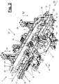
- Figure 1 shows a processing machine (2) for workpieces (3) which are guided along a conveying direction (7) by means of the guide device (1).
- the workpieces have an elongated shape and are preferably designed as profiles. They can be made of any material. They preferably consist of a wood material, the machine (2) being designed as a woodworking machine.
- the workpieces (3) are designed in particular as wooden profiles for window and furniture construction. These are wooden profiles that are manufactured to a specific cross-sectional shape and dimension in an upstream planing machine or the like and are then pretreated in the woodworking machine (2) for subsequent painting.
- processing devices (8, 9) are processed by means of one or more processing devices (8, 9) in the area of the guide device (1).
- These grinding devices (8) are located in corresponding free spaces (32) of the guide device (1) and are aligned transversely to the conveying direction (7).
- one or more further processing device devices can be present in the area of the guide device (1).
- These can be, for example, brush units for cleaning the workpiece (3) before and after grinding.
- one or two vertical brush units (9) are arranged in the entrance area of the guide device (1), the inclination of which can be changed by means of an adjusting device (10) and can also be delivered to the workpiece (3) transversely to the conveying direction (7).
- one or more further brush units (9), in particular horizontal brushes can be arranged between and behind the grinding devices (8).
- the height and width of the guide device (1) can be adjusted. It contains guide means (11, 12, 21, 22) which can move relative to one another. The adjustment is possible in one or two axes. It can be done manually or by means of a drive. In particular, an automatic adjustment based on a dimension and / or position input is possible by means of a suitable electronic control (not shown) and corresponding drives. The dimensions can be entered manually by an operator on site or remotely via data transmission.
- the processing machine (2) can have a suitable operating device with a display, for example a monitor, and possibly one or more interface (s) for data transmission.
- the guide device (1) has, for example, one or more relatively fixed height guide means (21) and side guide means (11) as well as one or more height guide means (22) and side guide means (12) which can be advanced transversely to the conveying direction (7).
- These guide means (11, 12, 21, 22) are arranged and aligned along the conveying direction (7). Together they form a guide channel (4) surrounding the workpiece (3).
- the guide means (11, 12, 21, 22) are arranged at right angles to one another and at a corner, and together they form a guide channel (4) with a rectangular cross-section.
- the processing machine (2) also has a conveying device (5) with which the workpiece (3) is transported into and through the guide device (1) and the processing machine (2).
- the conveyor device (5) has a conveyor drive (6) with conveyor rollers (23) which are arranged, for example, in the lower region of the conveyor device (1).
- the conveyor rollers (23) can be part of the lower and relatively fixed height guide means (21).
- the conveying device (5) can be designed and arranged in a different manner.
- the deliverable side and height guide means (12, 22) can be delivered together or independently of one another.
- the deliverable lateral guide means (12) having its own delivery device (19) with a horizontal delivery axis (20) transverse to the conveying direction (7).
- the adjustable height guide means (22) also has its own feed device (29) with a vertical feed axis (30).
- the delivery devices (19, 29) can be operated manually or by machine. In the exemplary embodiments shown, they each have their own controllable delivery drive.
- the feed drives can be connected to the mentioned control.
- the infeed can take place, for example, by specifying the position of the infeed and / or by specifying the dimensions of the workpiece (3).
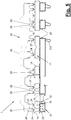
- the workpieces (3) in particular the wooden profiles, can have a very different cross-sectional shape. In the simplest case, they can be designed as a rectangular profile. In the preferred window and furniture construction sector, there are also other more complicated cross-sectional shapes with steps, curves or the like contours deviating from flat surfaces. Figures 7 and 8 show two examples of this. With the claimed guide device (1), any cross-sectional sizes and geometries of the workpieces (3) can be guided precisely and safely in the guide channel (4).
- the side and height guide means (12, 22) that can be advanced are mutually capable of engaging and overlapping at right angles to the conveying direction (7). Your delivery movements and delivery routes can cross each other. This allows very large and very small workpiece cross-sections to be guided.
- Figures 7 and 8 is the Engagement and overlap area (31) shown.
- the adjustable lateral and height guide means (12, 22) can also be designed to be capable of engaging and overlapping with an adjacent and relatively stationary side or height guide means (11, 21) transversely to the conveying direction (7). However, this is not absolutely necessary. You can also according to Figure 6 be arranged with a lateral or vertical offset and are moved past each other in the delivery without intervention.
- the lateral and vertical guide means (11, 12, 21, 22) each have a plurality of guide elements (13, 14, 23, 24) arranged in a row with a mutual spacing (18, 28) along the conveying direction (7).
- At least the spaced-apart guide elements (14, 24) of the adjustable lateral and height guide means (12, 22) are mutually offset with gaps in the conveying direction (7) and are thus arranged such that they can engage and overlap.
- the guide elements (13, 23) of the relatively stationary side and height guide means (11, 21) can be arranged in a row with a mutual spacing along the conveying direction (7) and offset with gaps.
- the straight extension of the guide elements (13, 14, 23, 24) results in flat envelope walls. Alternatively, contouring is possible.
- the number of guide elements (13,14,23,24) on the lateral and height guide means (11,12,21,22) can be the same or different. At least some of the lateral guide elements (13, 14) are preferably arranged directly opposite one another along the guide or conveying direction (7) and thus act on both sides in a guiding manner on the workpiece (3) at the same height. A corresponding opposite arrangement can also be present in the case of the upper and lower guide elements (23, 24).
- the guide elements (13, 14, 23, 24) can be designed in any suitable manner. They preferably have a straight extension in the contact area with the workpiece (3). In the illustrated and preferred exemplary embodiments, they are designed as rotatable, preferably cylindrical rollers, the axes of which are each aligned transversely to the conveying direction (7).
- the side rollers (13, 14) and the deliverable roof rollers (24) are freely rotatable on axles.
- the lower stationary guide elements or floor rollers (23) can be designed in the aforementioned manner as controllably driven conveyor rollers of the conveyor device (5).
- a drive can take place, for example, via the chain drives indicated in the drawings.
- one or more of any other guide elements (13, 14, 23, 24) can be designed as controllably driven conveyor rollers of the conveyor device (5).
- the cylindrical rollers (13,14,23,24) can have a jacket made of an elastic material, for example rubber.
- the jacket material can also have a high coefficient of friction, especially in the case of the floor or conveyor rollers (23).
- the diameter of the floor or conveyor rollers (23) can be larger than the diameter of the side and roof rollers (13,14,24). The same applies if, alternatively or in addition, other side or Height rollers (13,14,24) are designed as driven conveyor rollers.
- the deliverable guide elements (14, 24), in particular side and roof rollers, are each arranged on a slim support arm (17, 27) at the front, the support arm (17, 27) extending from a rear frame (16, 26) transversely to the Direction of conveyance (7) extends.
- the support arms (17, 27) are also spaced apart in the conveying direction (7).
- the horizontal and vertical support arms (17, 27) are mutually offset in a gap (18, 28) and thus arranged so that they can engage and overlap.
- Figure 4 and 5 illustrate this formation of side and roof rollers (14, 24) and their support arms (17, 27).
- the support arms (17, 27) each have a free cantilever length that is greater than the engagement and overlap path.
- the guide elements (14, 24) that can be advanced are spaced so far from their respective frames (16, 26) that collisions between the guide elements (14, 24) and the respective other frames (26, 16) during delivery and mutual overlap. be avoided.
- FIGs 7 and 8 the mutual engagement and overlap positions (31) are shown in each case.
- the deliverable side rollers (14) with their support arms (17) can each grip into the gaps (28) between the roof rollers (24) and their support arms (27) during horizontal delivery (20).
- the roof rollers (24) and support arms (27) each grip into the gaps (18) between the side rollers (14) during vertical delivery (30).
- the relatively stationary guide elements (13, 14) or side and bottom rollers or conveyor rollers can also be slender and in the manner described above be arranged spaced support arms. Alternatively, such an arrangement and the possibility of engagement and overlapping between adjustable and relatively stationary guide elements (13, 14, 23, 24) can be dispensed with.
- the length (1) of the guide elements (13,14,23,24) can be equal to or greater than the facing dimension (w) of the workpiece (3). This is for example at Figure 7 the height of the workpiece (3), which is smaller than the length of the side rollers (13,14). The same applies to the workpiece width and the floor and roof rollers (23, 24). Alternatively, the length (1) can be smaller than the facing dimension (w).
- the upright lateral guide elements (13, 14) are preferably arranged just above the lower guide elements (24).
- the workpiece (3) is enclosed tightly and circumferentially in the lower area.
- the adjustable lateral and height guide means (12, 22) each have an element holder (15, 25) for their guide elements (14, 24).
- the element holders (15, 25) each have one or more frames (16, 26) with said support arms (17, 27) for this purpose.
- the guide elements (14, 24) can be arranged individually or in groups, there being a gap between the groups in the conveying direction (7). In this way, for example, the aforementioned free spaces (32) for the processing devices (8, 9) can be formed.
- the frames (16, 26) are connected to one another and to their respective delivery device (19, 29) by bridging the distances by a common support beam or a support plate.
- the machine components in particular the guide device (1), the conveying device (5) and the processing devices (8, 9) can be controlled via the said electronic control of the woodworking machine. Regulation is also possible in conjunction with a suitable sensor system. Modifications of the embodiments shown and described are possible in various ways. In particular, the features of the exemplary embodiments can be combined with one another as desired or also interchanged.
Landscapes
- Life Sciences & Earth Sciences (AREA)
- Engineering & Computer Science (AREA)
- Mechanical Engineering (AREA)
- Wood Science & Technology (AREA)
- Forests & Forestry (AREA)
- Milling, Drilling, And Turning Of Wood (AREA)
- Framework For Endless Conveyors (AREA)
Claims (15)
- Appareil de guidage pour une pièce (3) déplaçable le long d'une direction de transport (7), en particulier un profilé en un matériau à base de bois, sur une machine d'usinage (2), en particulier une machine d'usinage de bois, l'appareil de guidage (1) guidant la pièce (3) le long d'une direction de transport (7) et étant configuré sous forme ajustable en hauteur et en largeur, et comprenant des moyens de guidage (11, 12, 21, 22), qui sont configurés sous forme mobile les uns relativement aux autres, ainsi que pour pouvoir s'engager et se chevaucher mutuellement perpendiculairement à la direction de transport (7),- l'appareil de guidage (1) comprenant un ou plusieurs moyens de guidage de hauteur et/ou latéraux (11, 21) relativement fixes et un ou plusieurs moyens de guidage de hauteur et latéraux (12, 22) ajustables perpendiculairement à la direction de transport (7),- les moyens de guidage de hauteur et latéraux ajustables (12, 22) étant configurés pour pouvoir s'engager et se chevaucher mutuellement perpendiculairement à la direction de transport (7),- les moyens de guidage de hauteur et latéraux ajustables (12, 22) et les moyens de guidage de hauteur et/ou latéraux relativement fixes (11, 21) comprenant respectivement plusieurs éléments de guidage (13, 14, 23, 24) agencés en une rangée avec un espacement mutuel (18, 28) le long de la direction de transport (7), qui sont respectivement configurés sous la forme de rouleau rotatif.
- Appareil de guidage selon la revendication 1, caractérisé en ce que les moyens de guidage de hauteur et latéraux ajustables (12, 22) sont configurés pour pouvoir s'engager et se chevaucher perpendiculairement à la direction de transport (7) par rapport à un moyen de guidage de hauteur ou latéral relativement fixe adjacent (11, 21), et/ou les moyens de guidage de hauteur et latéraux ajustables (12, 22) sont agencés avec un décalage latéral ou de hauteur perpendiculairement à la direction de transport (7) par rapport à un moyen de guidage de hauteur ou latéral relativement fixe adjacent (11, 21), et sont déplacés les uns devant les autres sans engagement lors de l'ajustement.
- Appareil de guidage selon l'une quelconque des revendications précédentes, caractérisé en ce qu'au moins certains éléments de guidage (13, 14, 23, 24), de préférence les éléments de guidage ajustables (14, 24), présentent une longueur dirigée perpendiculairement à la direction de transport (7), qui est supérieure ou égale à la dimension maximale de pièce lui faisant face (w) .
- Appareil de guidage selon l'une quelconque des revendications précédentes, caractérisé en ce que les éléments de guidage espacés (14, 24) des moyens de guidage latéraux et de hauteur ajustables (12, 22) sont agencés respectivement sur des vides (18, 28), ainsi que pour pouvoir s'engager et se chevaucher.
- Appareil de guidage selon l'une quelconque des revendications précédentes, caractérisé en ce que les éléments de guidage ajustables (14, 24) sont agencés respectivement du côté frontal sur un bras porteur étroit (17, 27), qui s'étend à partir d'un châssis du côté arrière (16, 26) perpendiculairement à la direction de transport (7), les bras porteurs (17, 27) dirigés perpendiculairement les uns aux autres étant agencés respectivement en décalage dans la direction de transport (7) sur des vides (18, 28), ainsi que pour pouvoir s'engager et se chevaucher.
- Appareil de guidage selon la revendication 5, caractérisé en ce que les moyens de guidage latéraux et de hauteur ajustables (12, 22) comprennent respectivement un support d'élément (15, 25), qui comprend un ou plusieurs châssis (16, 26) munis d'un ou de plusieurs bras porteurs (17, 27).
- Appareil de guidage selon l'une quelconque des revendications précédentes, caractérisé en ce qu'au moins un des éléments de guidage (13, 14, 23, 24) est configuré sous la forme d'un cylindre de transport entraîné de manière commandable (5).
- Appareil de guidage selon l'une quelconque des revendications précédentes, caractérisé en ce que les éléments de guidage (13, 14, 23, 24) sont agencés en groupes et forment dans la direction de transport (7) un ou plusieurs espaces libres plus grands (32) pour un appareil d'usinage (8, 9).
- Appareil de guidage selon l'une quelconque des revendications précédentes, caractérisé en ce que les moyens de guidage de hauteur et latéraux (11, 12, 21, 22) sont agencés et dirigés le long de la direction de transport (7).
- Appareil de guidage selon l'une quelconque des revendications précédentes, caractérisé en ce que les moyens de guidage de hauteur et latéraux (11, 12, 21, 22) sont agencés à angle droit les uns par rapport aux autres et en coin, ceux-ci formant un canal de guidage (4) rectangulaire dans la section transversale pour la pièce (3).
- Appareil de guidage selon l'une quelconque des revendications précédentes, caractérisé en ce qu'au moins certains des éléments de guidage latéraux (13, 14) sont agencés directement en face les uns des autres le long de la direction de transport (7) et agissent en guidage sur la pièce (3) à la même hauteur des deux côtés.
- Appareil de guidage selon l'une quelconque des revendications précédentes, caractérisé en ce que les moyens de guidage de hauteur et latéraux ajustables (12, 22) comprennent respectivement un dispositif d'ajustement (19, 29).
- Appareil de guidage selon la revendication 12, caractérisé en ce que les dispositifs d'ajustement (19, 29) comprennent des entraînements d'ajustement, qui sont reliés à une commande électronique.
- Machine d'usinage, en particulier machine d'usinage de bois, munie d'un appareil de guidage (1) pour une pièce (3) déplaçable le long d'une direction de transport (7), en particulier un profilé en un matériau à base de bois, caractérisée en ce que l'appareil de guidage (1) est configuré selon au moins l'une quelconque des revendications 1 à 13.
- Machine d'usinage selon la revendication 14, caractérisée en ce que la machine d'usinage (2) comprend un appareil d'usinage (8, 9), en particulier un appareil de ponçage et/ou une unité de brossage, dans la zone de l'appareil de guidage (1).
Applications Claiming Priority (1)
| Application Number | Priority Date | Filing Date | Title |
|---|---|---|---|
| DE202014105658.0U DE202014105658U1 (de) | 2014-11-25 | 2014-11-25 | Führungseinrichtung und Holzbearbeitungsmaschine |
Publications (2)
| Publication Number | Publication Date |
|---|---|
| EP3025834A1 EP3025834A1 (fr) | 2016-06-01 |
| EP3025834B1 true EP3025834B1 (fr) | 2021-08-04 |
Family
ID=54705032
Family Applications (1)
| Application Number | Title | Priority Date | Filing Date |
|---|---|---|---|
| EP15196022.6A Active EP3025834B1 (fr) | 2014-11-25 | 2015-11-24 | Dispositif de guidage |
Country Status (2)
| Country | Link |
|---|---|
| EP (1) | EP3025834B1 (fr) |
| DE (1) | DE202014105658U1 (fr) |
Families Citing this family (3)
| Publication number | Priority date | Publication date | Assignee | Title |
|---|---|---|---|---|
| CN106425526B (zh) * | 2016-12-05 | 2019-03-01 | 济南天辰铝机股份有限公司 | 一种高速动车组车体裙板的加工工装及加工方法 |
| CN112936451B (zh) * | 2021-01-27 | 2022-05-06 | 佛山市顺德区科雅力健锻压机床有限公司 | 一种具有防护机构的液压机械加工设备 |
| CN114654543A (zh) * | 2022-04-21 | 2022-06-24 | 宋圆 | 一种木材加工用双头铣设备 |
Citations (2)
| Publication number | Priority date | Publication date | Assignee | Title |
|---|---|---|---|---|
| DE2019729A1 (de) * | 1969-04-17 | 1970-11-05 | Hurn Brothers Eng Ltd | Verfahren und Vorrichtung zum Durchfuehren mehrerer Arbeiten an bestimmten Stellen eines vorzugsweise langgestreckten Werkstueckes |
| DE2406147A1 (de) * | 1973-02-07 | 1974-08-08 | Hurn Brothers Eng Ltd | Vorrichtung zum zerschneiden von holzbahnen u.dgl |
Family Cites Families (3)
| Publication number | Priority date | Publication date | Assignee | Title |
|---|---|---|---|---|
| IT1257800B (it) * | 1992-05-21 | 1996-02-13 | Scm Spa | Macchina scorniciatrice per la lavorazione del legno |
| US5979038A (en) * | 1997-09-17 | 1999-11-09 | Premark Rwp Holdings, Inc. | High-accuracy processing machine |
| DE19819170A1 (de) | 1998-04-29 | 1999-11-04 | Martin Otto Maschbau Gmbh | Abschaltvorrichtung an Werkzeugen, insbesondere an Mehrseitenhobelmaschinen |
-
2014
- 2014-11-25 DE DE202014105658.0U patent/DE202014105658U1/de not_active Expired - Lifetime
-
2015
- 2015-11-24 EP EP15196022.6A patent/EP3025834B1/fr active Active
Patent Citations (2)
| Publication number | Priority date | Publication date | Assignee | Title |
|---|---|---|---|---|
| DE2019729A1 (de) * | 1969-04-17 | 1970-11-05 | Hurn Brothers Eng Ltd | Verfahren und Vorrichtung zum Durchfuehren mehrerer Arbeiten an bestimmten Stellen eines vorzugsweise langgestreckten Werkstueckes |
| DE2406147A1 (de) * | 1973-02-07 | 1974-08-08 | Hurn Brothers Eng Ltd | Vorrichtung zum zerschneiden von holzbahnen u.dgl |
Also Published As
| Publication number | Publication date |
|---|---|
| EP3025834A1 (fr) | 2016-06-01 |
| DE202014105658U1 (de) | 2016-02-25 |
Similar Documents
| Publication | Publication Date | Title |
|---|---|---|
| EP3689563B1 (fr) | Unité de chevauchement pour le chevauchement latéral de portions transportées dans une direction longitudinale | |
| DE69003391T2 (de) | Pressenstrasseanordnung. | |
| EP2732942B1 (fr) | Machine de découpe de portail et procédé de découpe de plaques grand format | |
| WO2015165429A1 (fr) | Procédé et dispositif pour produire des découpes de pâtes à partir d'une ou de plusieurs bandes de pâtes | |
| EP3025834B1 (fr) | Dispositif de guidage | |
| DE19740222A1 (de) | Vorrichtung zum Führen einer Endlospapierbahn | |
| DE1778337B1 (de) | Endloser foerderer zur verwendung bei einer automatischen lackieranlage fuer plattenfoermige werkstuecke | |
| EP3492231B1 (fr) | Dispositif de traitement des bords | |
| DE102020129750A1 (de) | Verfahren zum Quer-Positionieren eines zu transportierenden Artikels | |
| DE102018133552B4 (de) | Biegemaschine, Bearbeitungslinie und Verfahren zum Biegen | |
| DE19627148C1 (de) | Vorrichtung zum beidseitigen Beschleifen von Steinen | |
| EP2565015B1 (fr) | Dispositif et procédé destinés au rééquipement de machines d'enrobage de profilés | |
| EP3141122B1 (fr) | Dispositif et procédé d'injection latérale d'une bande de pâte | |
| EP2481540B1 (fr) | Dispositif de sciage d'au moins deux pièces usinées sous forme de plaques ou de piles de plaques | |
| DE2745325C2 (de) | Kantenbesäumvorrichtung für einen Kautschukstreifen mit Verstärkungseinlage | |
| DE29611728U1 (de) | Vorrichtung zum beidseitigen Beschleifen von Steinen | |
| EP0489681B1 (fr) | Procédé et dispositif pour déplacer des pièces en forme de bandes ou de panneaux, empilés et juxtaposés sur une surface de support à faible coefficient de frottement | |
| EP3333100A1 (fr) | Dispositif de transport et procédé de transport pour une ligne d'assemblage pourvue d'au moins un emplacement de montage | |
| DE102009052336A1 (de) | Ladevorrichtung für Werkstoffstangen | |
| DE4212432A1 (de) | Vorrichtung zum spanlosen Abschneiden von Holzlamellen von einem Kantholz | |
| AT514262A2 (de) | Bearbeitungsanlage und Schleifeinheit | |
| AT515432B1 (de) | Vorschub- und Richtvorrichtung | |
| EP3369663B1 (fr) | Dispositif de bottelage pour pièces à usiner oblongues ainsi que procédé de bottelage de pièces à usiner oblongues | |
| EP1407835A1 (fr) | Dispositif de nettoyage d'articles sensiblement parallélépipédiques | |
| DE10303136B3 (de) | Band- und Platinenabstützung für ein Schneidwerkzeug mit zwei Schneidbalken |
Legal Events
| Date | Code | Title | Description |
|---|---|---|---|
| PUAI | Public reference made under article 153(3) epc to a published international application that has entered the european phase |
Free format text: ORIGINAL CODE: 0009012 |
|
| AK | Designated contracting states |
Kind code of ref document: A1 Designated state(s): AL AT BE BG CH CY CZ DE DK EE ES FI FR GB GR HR HU IE IS IT LI LT LU LV MC MK MT NL NO PL PT RO RS SE SI SK SM TR |
|
| AX | Request for extension of the european patent |
Extension state: BA ME |
|
| STAA | Information on the status of an ep patent application or granted ep patent |
Free format text: STATUS: REQUEST FOR EXAMINATION WAS MADE |
|
| 17P | Request for examination filed |
Effective date: 20161201 |
|
| RBV | Designated contracting states (corrected) |
Designated state(s): AL AT BE BG CH CY CZ DE DK EE ES FI FR GB GR HR HU IE IS IT LI LT LU LV MC MK MT NL NO PL PT RO RS SE SI SK SM TR |
|
| STAA | Information on the status of an ep patent application or granted ep patent |
Free format text: STATUS: EXAMINATION IS IN PROGRESS |
|
| 17Q | First examination report despatched |
Effective date: 20170728 |
|
| GRAP | Despatch of communication of intention to grant a patent |
Free format text: ORIGINAL CODE: EPIDOSNIGR1 |
|
| STAA | Information on the status of an ep patent application or granted ep patent |
Free format text: STATUS: GRANT OF PATENT IS INTENDED |
|
| INTG | Intention to grant announced |
Effective date: 20201218 |
|
| GRAJ | Information related to disapproval of communication of intention to grant by the applicant or resumption of examination proceedings by the epo deleted |
Free format text: ORIGINAL CODE: EPIDOSDIGR1 |
|
| STAA | Information on the status of an ep patent application or granted ep patent |
Free format text: STATUS: EXAMINATION IS IN PROGRESS |
|
| INTC | Intention to grant announced (deleted) | ||
| GRAP | Despatch of communication of intention to grant a patent |
Free format text: ORIGINAL CODE: EPIDOSNIGR1 |
|
| STAA | Information on the status of an ep patent application or granted ep patent |
Free format text: STATUS: GRANT OF PATENT IS INTENDED |
|
| INTG | Intention to grant announced |
Effective date: 20210323 |
|
| GRAS | Grant fee paid |
Free format text: ORIGINAL CODE: EPIDOSNIGR3 |
|
| GRAA | (expected) grant |
Free format text: ORIGINAL CODE: 0009210 |
|
| STAA | Information on the status of an ep patent application or granted ep patent |
Free format text: STATUS: THE PATENT HAS BEEN GRANTED |
|
| AK | Designated contracting states |
Kind code of ref document: B1 Designated state(s): AL AT BE BG CH CY CZ DE DK EE ES FI FR GB GR HR HU IE IS IT LI LT LU LV MC MK MT NL NO PL PT RO RS SE SI SK SM TR |
|
| REG | Reference to a national code |
Ref country code: GB Ref legal event code: FG4D Free format text: NOT ENGLISH |
|
| REG | Reference to a national code |
Ref country code: AT Ref legal event code: REF Ref document number: 1416504 Country of ref document: AT Kind code of ref document: T Effective date: 20210815 |
|
| REG | Reference to a national code |
Ref country code: CH Ref legal event code: EP |
|
| REG | Reference to a national code |
Ref country code: DE Ref legal event code: R096 Ref document number: 502015015026 Country of ref document: DE |
|
| REG | Reference to a national code |
Ref country code: IE Ref legal event code: FG4D Free format text: LANGUAGE OF EP DOCUMENT: GERMAN |
|
| REG | Reference to a national code |
Ref country code: LT Ref legal event code: MG9D |
|
| REG | Reference to a national code |
Ref country code: NL Ref legal event code: MP Effective date: 20210804 |
|
| PG25 | Lapsed in a contracting state [announced via postgrant information from national office to epo] |
Ref country code: LT Free format text: LAPSE BECAUSE OF FAILURE TO SUBMIT A TRANSLATION OF THE DESCRIPTION OR TO PAY THE FEE WITHIN THE PRESCRIBED TIME-LIMIT Effective date: 20210804 Ref country code: BG Free format text: LAPSE BECAUSE OF FAILURE TO SUBMIT A TRANSLATION OF THE DESCRIPTION OR TO PAY THE FEE WITHIN THE PRESCRIBED TIME-LIMIT Effective date: 20211104 Ref country code: NO Free format text: LAPSE BECAUSE OF FAILURE TO SUBMIT A TRANSLATION OF THE DESCRIPTION OR TO PAY THE FEE WITHIN THE PRESCRIBED TIME-LIMIT Effective date: 20211104 Ref country code: PT Free format text: LAPSE BECAUSE OF FAILURE TO SUBMIT A TRANSLATION OF THE DESCRIPTION OR TO PAY THE FEE WITHIN THE PRESCRIBED TIME-LIMIT Effective date: 20211206 Ref country code: FI Free format text: LAPSE BECAUSE OF FAILURE TO SUBMIT A TRANSLATION OF THE DESCRIPTION OR TO PAY THE FEE WITHIN THE PRESCRIBED TIME-LIMIT Effective date: 20210804 Ref country code: ES Free format text: LAPSE BECAUSE OF FAILURE TO SUBMIT A TRANSLATION OF THE DESCRIPTION OR TO PAY THE FEE WITHIN THE PRESCRIBED TIME-LIMIT Effective date: 20210804 Ref country code: SE Free format text: LAPSE BECAUSE OF FAILURE TO SUBMIT A TRANSLATION OF THE DESCRIPTION OR TO PAY THE FEE WITHIN THE PRESCRIBED TIME-LIMIT Effective date: 20210804 Ref country code: RS Free format text: LAPSE BECAUSE OF FAILURE TO SUBMIT A TRANSLATION OF THE DESCRIPTION OR TO PAY THE FEE WITHIN THE PRESCRIBED TIME-LIMIT Effective date: 20210804 Ref country code: HR Free format text: LAPSE BECAUSE OF FAILURE TO SUBMIT A TRANSLATION OF THE DESCRIPTION OR TO PAY THE FEE WITHIN THE PRESCRIBED TIME-LIMIT Effective date: 20210804 |
|
| PG25 | Lapsed in a contracting state [announced via postgrant information from national office to epo] |
Ref country code: PL Free format text: LAPSE BECAUSE OF FAILURE TO SUBMIT A TRANSLATION OF THE DESCRIPTION OR TO PAY THE FEE WITHIN THE PRESCRIBED TIME-LIMIT Effective date: 20210804 Ref country code: LV Free format text: LAPSE BECAUSE OF FAILURE TO SUBMIT A TRANSLATION OF THE DESCRIPTION OR TO PAY THE FEE WITHIN THE PRESCRIBED TIME-LIMIT Effective date: 20210804 Ref country code: GR Free format text: LAPSE BECAUSE OF FAILURE TO SUBMIT A TRANSLATION OF THE DESCRIPTION OR TO PAY THE FEE WITHIN THE PRESCRIBED TIME-LIMIT Effective date: 20211105 |
|
| PG25 | Lapsed in a contracting state [announced via postgrant information from national office to epo] |
Ref country code: NL Free format text: LAPSE BECAUSE OF FAILURE TO SUBMIT A TRANSLATION OF THE DESCRIPTION OR TO PAY THE FEE WITHIN THE PRESCRIBED TIME-LIMIT Effective date: 20210804 |
|
| PG25 | Lapsed in a contracting state [announced via postgrant information from national office to epo] |
Ref country code: DK Free format text: LAPSE BECAUSE OF FAILURE TO SUBMIT A TRANSLATION OF THE DESCRIPTION OR TO PAY THE FEE WITHIN THE PRESCRIBED TIME-LIMIT Effective date: 20210804 |
|
| REG | Reference to a national code |
Ref country code: DE Ref legal event code: R097 Ref document number: 502015015026 Country of ref document: DE |
|
| PG25 | Lapsed in a contracting state [announced via postgrant information from national office to epo] |
Ref country code: SM Free format text: LAPSE BECAUSE OF FAILURE TO SUBMIT A TRANSLATION OF THE DESCRIPTION OR TO PAY THE FEE WITHIN THE PRESCRIBED TIME-LIMIT Effective date: 20210804 Ref country code: SK Free format text: LAPSE BECAUSE OF FAILURE TO SUBMIT A TRANSLATION OF THE DESCRIPTION OR TO PAY THE FEE WITHIN THE PRESCRIBED TIME-LIMIT Effective date: 20210804 Ref country code: RO Free format text: LAPSE BECAUSE OF FAILURE TO SUBMIT A TRANSLATION OF THE DESCRIPTION OR TO PAY THE FEE WITHIN THE PRESCRIBED TIME-LIMIT Effective date: 20210804 Ref country code: EE Free format text: LAPSE BECAUSE OF FAILURE TO SUBMIT A TRANSLATION OF THE DESCRIPTION OR TO PAY THE FEE WITHIN THE PRESCRIBED TIME-LIMIT Effective date: 20210804 Ref country code: CZ Free format text: LAPSE BECAUSE OF FAILURE TO SUBMIT A TRANSLATION OF THE DESCRIPTION OR TO PAY THE FEE WITHIN THE PRESCRIBED TIME-LIMIT Effective date: 20210804 Ref country code: AL Free format text: LAPSE BECAUSE OF FAILURE TO SUBMIT A TRANSLATION OF THE DESCRIPTION OR TO PAY THE FEE WITHIN THE PRESCRIBED TIME-LIMIT Effective date: 20210804 |
|
| PLBE | No opposition filed within time limit |
Free format text: ORIGINAL CODE: 0009261 |
|
| STAA | Information on the status of an ep patent application or granted ep patent |
Free format text: STATUS: NO OPPOSITION FILED WITHIN TIME LIMIT |
|
| PG25 | Lapsed in a contracting state [announced via postgrant information from national office to epo] |
Ref country code: MC Free format text: LAPSE BECAUSE OF FAILURE TO SUBMIT A TRANSLATION OF THE DESCRIPTION OR TO PAY THE FEE WITHIN THE PRESCRIBED TIME-LIMIT Effective date: 20210804 |
|
| 26N | No opposition filed |
Effective date: 20220506 |
|
| GBPC | Gb: european patent ceased through non-payment of renewal fee |
Effective date: 20211124 |
|
| PG25 | Lapsed in a contracting state [announced via postgrant information from national office to epo] |
Ref country code: LU Free format text: LAPSE BECAUSE OF NON-PAYMENT OF DUE FEES Effective date: 20211124 Ref country code: BE Free format text: LAPSE BECAUSE OF NON-PAYMENT OF DUE FEES Effective date: 20211130 |
|
| REG | Reference to a national code |
Ref country code: BE Ref legal event code: MM Effective date: 20211130 |
|
| PG25 | Lapsed in a contracting state [announced via postgrant information from national office to epo] |
Ref country code: SI Free format text: LAPSE BECAUSE OF FAILURE TO SUBMIT A TRANSLATION OF THE DESCRIPTION OR TO PAY THE FEE WITHIN THE PRESCRIBED TIME-LIMIT Effective date: 20210804 |
|
| PG25 | Lapsed in a contracting state [announced via postgrant information from national office to epo] |
Ref country code: IE Free format text: LAPSE BECAUSE OF NON-PAYMENT OF DUE FEES Effective date: 20211124 Ref country code: GB Free format text: LAPSE BECAUSE OF NON-PAYMENT OF DUE FEES Effective date: 20211124 |
|
| PG25 | Lapsed in a contracting state [announced via postgrant information from national office to epo] |
Ref country code: HU Free format text: LAPSE BECAUSE OF FAILURE TO SUBMIT A TRANSLATION OF THE DESCRIPTION OR TO PAY THE FEE WITHIN THE PRESCRIBED TIME-LIMIT; INVALID AB INITIO Effective date: 20151124 |
|
| PG25 | Lapsed in a contracting state [announced via postgrant information from national office to epo] |
Ref country code: CY Free format text: LAPSE BECAUSE OF FAILURE TO SUBMIT A TRANSLATION OF THE DESCRIPTION OR TO PAY THE FEE WITHIN THE PRESCRIBED TIME-LIMIT Effective date: 20210804 |
|
| PGFP | Annual fee paid to national office [announced via postgrant information from national office to epo] |
Ref country code: FR Payment date: 20231124 Year of fee payment: 9 Ref country code: CH Payment date: 20231201 Year of fee payment: 9 Ref country code: AT Payment date: 20231117 Year of fee payment: 9 |
|
| PG25 | Lapsed in a contracting state [announced via postgrant information from national office to epo] |
Ref country code: MK Free format text: LAPSE BECAUSE OF FAILURE TO SUBMIT A TRANSLATION OF THE DESCRIPTION OR TO PAY THE FEE WITHIN THE PRESCRIBED TIME-LIMIT Effective date: 20210804 |
|
| PG25 | Lapsed in a contracting state [announced via postgrant information from national office to epo] |
Ref country code: MT Free format text: LAPSE BECAUSE OF FAILURE TO SUBMIT A TRANSLATION OF THE DESCRIPTION OR TO PAY THE FEE WITHIN THE PRESCRIBED TIME-LIMIT Effective date: 20210804 |
|
| REG | Reference to a national code |
Ref country code: CH Ref legal event code: PL |
|
| REG | Reference to a national code |
Ref country code: AT Ref legal event code: MM01 Ref document number: 1416504 Country of ref document: AT Kind code of ref document: T Effective date: 20241124 Ref country code: CH Ref legal event code: PL |
|
| PG25 | Lapsed in a contracting state [announced via postgrant information from national office to epo] |
Ref country code: CH Free format text: LAPSE BECAUSE OF NON-PAYMENT OF DUE FEES Effective date: 20241130 |
|
| PG25 | Lapsed in a contracting state [announced via postgrant information from national office to epo] |
Ref country code: AT Free format text: LAPSE BECAUSE OF NON-PAYMENT OF DUE FEES Effective date: 20241124 |
|
| PG25 | Lapsed in a contracting state [announced via postgrant information from national office to epo] |
Ref country code: FR Free format text: LAPSE BECAUSE OF NON-PAYMENT OF DUE FEES Effective date: 20241130 |
|
| PG25 | Lapsed in a contracting state [announced via postgrant information from national office to epo] |
Ref country code: TR Free format text: LAPSE BECAUSE OF FAILURE TO SUBMIT A TRANSLATION OF THE DESCRIPTION OR TO PAY THE FEE WITHIN THE PRESCRIBED TIME-LIMIT Effective date: 20210804 |
|
| PGFP | Annual fee paid to national office [announced via postgrant information from national office to epo] |
Ref country code: DE Payment date: 20251118 Year of fee payment: 11 |
|
| PGFP | Annual fee paid to national office [announced via postgrant information from national office to epo] |
Ref country code: IT Payment date: 20251128 Year of fee payment: 11 |