EP3032067A1 - Melangeur de gaz d'un moteur a combustion d'une centrale de cogeneration pour le fonctionnement a l'aide d'un gaz de bois - Google Patents
Melangeur de gaz d'un moteur a combustion d'une centrale de cogeneration pour le fonctionnement a l'aide d'un gaz de bois Download PDFInfo
- Publication number
- EP3032067A1 EP3032067A1 EP15003190.4A EP15003190A EP3032067A1 EP 3032067 A1 EP3032067 A1 EP 3032067A1 EP 15003190 A EP15003190 A EP 15003190A EP 3032067 A1 EP3032067 A1 EP 3032067A1
- Authority
- EP
- European Patent Office
- Prior art keywords
- gas
- compressor
- stream
- gas mixer
- mixer
- Prior art date
- Legal status (The legal status is an assumption and is not a legal conclusion. Google has not performed a legal analysis and makes no representation as to the accuracy of the status listed.)
- Withdrawn
Links
Images


Classifications
-
- F—MECHANICAL ENGINEERING; LIGHTING; HEATING; WEAPONS; BLASTING
- F02—COMBUSTION ENGINES; HOT-GAS OR COMBUSTION-PRODUCT ENGINE PLANTS
- F02B—INTERNAL-COMBUSTION PISTON ENGINES; COMBUSTION ENGINES IN GENERAL
- F02B43/00—Engines characterised by operating on gaseous fuels; Plants including such engines
- F02B43/08—Plants characterised by the engines using gaseous fuel generated in the plant from solid fuel, e.g. wood
-
- Y—GENERAL TAGGING OF NEW TECHNOLOGICAL DEVELOPMENTS; GENERAL TAGGING OF CROSS-SECTIONAL TECHNOLOGIES SPANNING OVER SEVERAL SECTIONS OF THE IPC; TECHNICAL SUBJECTS COVERED BY FORMER USPC CROSS-REFERENCE ART COLLECTIONS [XRACs] AND DIGESTS
- Y02—TECHNOLOGIES OR APPLICATIONS FOR MITIGATION OR ADAPTATION AGAINST CLIMATE CHANGE
- Y02T—CLIMATE CHANGE MITIGATION TECHNOLOGIES RELATED TO TRANSPORTATION
- Y02T10/00—Road transport of goods or passengers
- Y02T10/10—Internal combustion engine [ICE] based vehicles
- Y02T10/30—Use of alternative fuels, e.g. biofuels
Definitions
- the invention relates to a gas mixer for the mixture of air and wood gas of an internal combustion engine of a combined heat and power plant (CHP) for operation with a wood gas according to the preamble of claim 1, and a CHP using a compressor and a gas mixer.
- CHP combined heat and power plant
- the invention is not based on combined heat and power with the production of a wood gas from a lumpy Good, such. B. wood, but the wood gas can be generated in the context of the present invention by other carbonaceous biomass substances such. Wood pellets, bark products, sewage sludge, straw and other combustible biomass materials.
- wood gas used here is therefore to be understood broadly, because all the above-mentioned substances can be gasified. It is therefore used for convenience of description only and is not limited to the word meaning "wood gas”.
- Power heat couplings with the gas generation from a carbonaceous raw material in particular wood are often equipped for simplicity with a free-absorbing gas engine as a heat engine.
- the invention has the task of improving the efficiency, wear and susceptibility of a CHP with charging significantly.
- the invention is characterized by the technical teaching of claim 1.
- a compressor and gas mixer which operates with much higher efficiency and is trouble-free and reliable over a longer period of operation.
- the compressor can be designed in one or more stages. The simpler description is based on a single-stage compressor, although the invention also includes multi-stage compressor.
- the device for charging the engine preferably consists of a radial compressor / centrifugal compressor, which is used inter alia in the turbocharger in motor vehicle engines.
- Other possibilities for engine charging are screw compressors, axial compressors, reciprocating compressors, disk compressors and the like.
- the drive of the centrifugal compressor is preferably carried out, as is customary in turbochargers, via a shaft with a turbine via the exhaust gas pressure of the gas engine.
- Other versions of the drive are electric motors, rotational energy of the crankshaft of the gas engine or the like.
- Negative components of the gas produced which deteriorate its quality in terms of subsequent conversion include water, particulates (e.g., dust, coal, slag), tars, oils.
- a complete cleaning of all negative components of the gas is associated with great effort and usually requires a multi-stage cleaning system of scrubbers and / or filter systems and / or the like.
- the gas generated by the gas generator is mixed with ambient air about 5-5000cm before the entry of a radial compressor of the gas engine to obtain an ignitable gas mixture.
- the water now forms drops of different sizes and moves in the air-gas mixture together with the other remaining detrimental gas components to the compressor.
- a radial compressor requires a relatively high peripheral speed of the compressor wheel about its own axis. This can be in the range of about 100-700m / s at the extreme point. Now enters the gas mixture together with its solid and / or liquid components in the compressor, it inevitably impacts the water, dust, etc. with the rapidly moving compressor wheel. These impacts can be so strong that a material removal of the wheel takes place or parts of the wheel are damaged by erosion and peeled off. For compressors in the automotive sector, this phenomenon is also known as drop or particle impact. The medium to be compressed there, however, is not to be compared with that of a wood gas combined heat and power in terms of its particle freedom.
- a gas mixer according to the invention is connected upstream of the radial compressor.
- the impact velocity of the contaminants harmful to the compressor can thus be reduced in the range of 30-70%. As a result, wear on the compressor is greatly reduced or even completely avoided.
- the compressor housing is protected from deposits by tars or similar adhesive and abrasive substances.
- the likelihood of loosening encrustations that can cause damage to the compressor wheel is effectively reduced.
- the gas can also be fed to the centrifugal compressor before the gas engine, this gas with pressure ⁇ boost pressure radial compressor> ambient pressure must be introduced, this can be done via another compressor or the same compressor with possibly downstream throttle if this already pressurized the reactor for gas production.
- stainless steel alloys or titanium alloys or very hard and / or tough materials are selected for the material of the compressor wheel to reduce wear by impacting particles.
- Feature of the present invention is therefore that the compressor is now preceded by a gas mixer according to the invention, which consists essentially of a surrounding housing for guiding a non-combustible and almost particle- and tar-free air flow, wherein coaxially in the housing a nozzle tube is arranged so that between the outer circumference of the nozzle tube and the inner circumference of the housing forms an annular space, via which the air flow is supplied.
- a gas mixer according to the invention, which consists essentially of a surrounding housing for guiding a non-combustible and almost particle- and tar-free air flow, wherein coaxially in the housing a nozzle tube is arranged so that between the outer circumference of the nozzle tube and the inner circumference of the housing forms an annular space, via which the air flow is supplied.
- the air flow flows along the outer circumference of the nozzle tube and in the interior of the nozzle tube flows the particle and teerbehaftete gas stream, which is directed in the region of the nozzle tube on the front nozzle orifice against the central region of the compressor wheel, wherein the gas stream of the guided at the outer periphery of the gas stream air flow envelops is and is centered by this on the central axis of rotation of the compressor wheel.
- the gas stream contaminated with particles and other foreign substances is directed onto the centric part of the compressor wheel which moves at a slower speed.
- the center of rotation is formed by the compressor shaft or compressor nut and against this area, the gas stream enclosed with a pure air flow is supplied. This avoids that contaminated with particles gas stream impinges on the outer peripheral peripheral parts of the compressor wheel at a greater peripheral speed, because it is surrounded by a clean, particle-free air flow and centered.
- the air stream enveloping the contaminating gas stream acts, to some degree, as an air-assisted tubular guide device centering the gas flow on the center of the compressor wheel.
- vanes can straighten the airflow in the direction of flow to achieve a laminar airflow that envelops the contaminated gas stream.
- the guide vanes are oriented obliquely to one in itself To produce rotating air flow, which surrounds the guided in the central region gas stream in a rotating motion and helically with it.
- the portion of the nozzle tube located just before the nozzle orifice is cylindrical, d. H. it is formed in the axial direction rectilinear with the same diameter.
- this section which leads the particle-laden gas flow in front of the nozzle orifice of the nozzle tube, is conically narrowed conically in the sense of a constriction and thus forms a narrowing nozzle orifice.
- additional guide vanes are arranged in the interior of the nozzle tube, which provide either for a laminar flow and for an additional centering of the particle-laden gas flow to the central region of the compressor wheel.
- these vanes may also be bevelled to produce a rotating gas stream which is centered on the center region of the compressor wheel.
- outer air flow guide vanes may be combined with any other type of guide vanes for guiding the particulate gas flow.
- the invention is completely free in the choice of the internal combustion engine to which the gas-air mixture prepared according to the invention is supplied.
- It can be designed as a piston internal combustion engine, as a rotary piston internal combustion engine or in any other type of internal combustion engine with which it is possible to convert an ignitable gas-air mixture into a rotating energy, finally to drive an electric generator with this engine and with this Generate electricity.
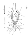
- a wood gas plant 1 which consists essentially of a gas generator 2, which is formed by a reactor consisting of a housing, in the upper region of air entrainments 6 are arranged. Combustion takes place in the reactor to form an upper oxidation zone 7 and a lower reduction zone 8.
- a wood gas plant is for example in the EP1436364B1 of the same applicant, the disclosure of which is intended to be fully encompassed by the disclosure of this invention.
- biomass substances are burned in a conventional manner, such as. As pieces of wood, pellets and other substances, as indicated in the general description introduction.
- a grate In the lower region of the reactor, a grate is arranged, which in the illustrated embodiment consists of two rotatably driven grate disks 3, 4, which operate in the ember bed 5.
- the combustible gas produced in this gas generator 2 is supplied via a line 9 to a gas cooler 10 connected downstream and fed to the output thereof via a line 11 to a filter 12.
- the filter 12 separates the majority of harmful particles from the gas stream and the output 13 of the filter 12 is connected via a line 14 to the input of the CHP 60.
- the CHP plant 60 consists of a gas mixer 21, in which the mixture according to the invention of an air stream 41 drawn from the atmosphere takes place with the ignitable gas stream 24 from the gas generator 2, the compressor 25 in the embodiment shown is via a drive shaft 17 from a turbine 18th is driven, which in turn is driven by the exhaust stream of an internal combustion engine 34.
- the exhaust gas flow of the exhaust gas 31 is introduced via the line 32 from the exhaust manifold of the internal combustion engine 34 in the inlet 33 of the turbine 18, and drives them in rotation, after which the exhaust gas 20 is discharged from the turbine 18 in the direction of arrow 19.
- the compressor 25 brings about a compression of the gas flow sucked in through the gas mixer 21.
- the internal combustion engine runs with the gas-air mixture 26 produced according to the invention and transmits its rotational energy via a drive shaft 35 to a downstream generator 36, which is thereby driven in rotation, and generates electricity which can be taken off at the current output 37.
- the ignitable gas-air mixture 26 is introduced into the intake pipe 28 of the internal combustion engine 34 and fed via a plurality of cylinder inlets 29 to the combustion chamber of the internal combustion engine 34.
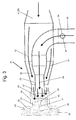
- the gas mixer 21 according to the invention allows the greatest possible protection of the compressor wheel 25 of the compressor 16 and thus a long term of the CHP 60th
- the gas mixer 21 according to FIG. 2 from an elongated, approximately cylindrical housing 22, which sucks at its central inlet opening an air flow 41 from the atmosphere.
- the air flow 41 is guided on the inner circumference of the housing 22 over the outer circumference of a coaxially arranged in the housing 22 nozzle tube 23, so that the nozzle tube 23 is surrounded on all sides on its outer periphery by the air flow 41.
- the air stream 41 surrounds the centrally guided therein gas stream 24 in the region of the nozzle orifice 40 and forms, so to speak, an air-supported pipe for guiding the gas stream 24, as in FIG. 6 is shown.
- the air flow 41 flows in the direction of arrow 55 and forms an approximately cylindrical full enclosing casing 54 for this gas stream 24.
- the gas stream 24 is therefore guided centrally by the enveloping air flow 41 (envelope 44) against the low-speed rotating central, inner region of the compressor wheel 25, as in FIG. 6 is shown.
- the envelope 54 of the gas stream 24 with the air stream 41 takes place in a mixing chamber 43 in the housing 23 of the gas mixer, said mixing chamber is to be kept short in its axial length. It should prevent there be that the gas stream 24 breaks out of the enveloping air flow 41, so that the axial length of the mixing chamber 43 is short.
- the compressor wheel 25 rotates in a compressor housing 38 at a very high peripheral speed (see general description part) and the annular space 42 is continued into the mixing chamber 43 in the axial direction and opens into it.
- the gas flow 24 enveloped by the air flow 41 is conducted as a mixed flow 59 in the direction of the compressor nut 48 of the rotating compressor wheel 25, because there are the parts of the compressor wheel 25 running at the lowest speed of movement.
- the central region of the compressor wheel 25 is formed by a solid core 39, which is not flowed through by the gas streams.
- the compressor wheel 25 is formed from a number of rotating compressor blades 44, wherein the compressor blade 44 radially inwardly each form blade upper edges 52, which extend into the mixing chamber 43 inside.
- FIG. 2 In one embodiment of the present invention is in dashed lines in FIG. 2 shown that optionally on the inner circumference of the housing 22 are arranged evenly distributed in the flow direction in the axial direction vanes 45 on the circumference, which provide a laminar air flow of the air flow 41 in the direction of the nozzle orifice 40.
- vanes 45 may also be bevelled to produce a rotating air flow 41 in the region of the nozzle orifice 40.
- vanes - such as the vanes 45 - may be arranged, evenly distributed around the circumference in the interior of the nozzle tube 23rd are arranged in the vicinity of the nozzle orifice 40, to either - in a first embodiment - to even further straighten the gas stream 24 and to provide for a laminar gas flow or - in a second embodiment - the mitigation of the gas flow 24.
- crankcase vent 47 opens, which is led by the engine 34 zoom.
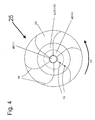
- FIG. 4 shows that the compressor wheel 25 can be substantially subdivided into a radial outer region 50 by the compressor blades 44 are arranged, wherein an annular space 42 connects with the inlet portion 51 radially inwardly of this outer region 50.
- the nozzle orifice 40 Radially inwardly to the annular space 42 then the nozzle orifice 40 according to the invention is arranged, which is arranged in the mixing chamber 43 and via which the gas stream 24 is introduced.
Landscapes
- Engineering & Computer Science (AREA)
- Chemical & Material Sciences (AREA)
- Combustion & Propulsion (AREA)
- Mechanical Engineering (AREA)
- General Engineering & Computer Science (AREA)
- Structures Of Non-Positive Displacement Pumps (AREA)
Applications Claiming Priority (1)
| Application Number | Priority Date | Filing Date | Title |
|---|---|---|---|
| DE102014016855.7A DE102014016855A1 (de) | 2014-11-14 | 2014-11-14 | Gasmischer eines Verbrennungsmotors eines BHKW für den Betrieb mit einem Holzgas |
Publications (1)
| Publication Number | Publication Date |
|---|---|
| EP3032067A1 true EP3032067A1 (fr) | 2016-06-15 |
Family
ID=54539798
Family Applications (1)
| Application Number | Title | Priority Date | Filing Date |
|---|---|---|---|
| EP15003190.4A Withdrawn EP3032067A1 (fr) | 2014-11-14 | 2015-11-06 | Melangeur de gaz d'un moteur a combustion d'une centrale de cogeneration pour le fonctionnement a l'aide d'un gaz de bois |
Country Status (2)
| Country | Link |
|---|---|
| EP (1) | EP3032067A1 (fr) |
| DE (1) | DE102014016855A1 (fr) |
Citations (11)
| Publication number | Priority date | Publication date | Assignee | Title |
|---|---|---|---|---|
| US726238A (en) * | 1902-07-11 | 1903-04-28 | David John Archer | Gas and air mixer. |
| GB191005575A (en) * | 1910-03-05 | 1911-02-02 | Victor Cazes | Improvements relating to the Application of Gas Producers to Motor Vehicles. |
| WO2007089565A1 (fr) * | 2006-01-27 | 2007-08-09 | Borgwarner Inc. | Unité de mélange permettant de réintroduire un condensat de recyclage des gaz d'échappement à basse pression dans le compresseur |
| WO2007089567A1 (fr) * | 2006-01-27 | 2007-08-09 | Borgwarner Inc. | Unité de réintroduction d'un condensat de recyclage des gaz d'échappement à basse pression avant ou au niveau du compresseur |
| JP2009024692A (ja) * | 2007-06-21 | 2009-02-05 | Toyota Motor Corp | 内燃機関の排気還流装置 |
| EP1436364B1 (fr) | 2001-05-31 | 2010-06-30 | Bernd Joos | Dispositif de production d'un melange gazeux combustible |
| WO2010101728A2 (fr) * | 2009-03-03 | 2010-09-10 | Borgwarner Inc. | Turbocompresseur |
| GB2488997A (en) * | 2011-03-14 | 2012-09-19 | O Gen Uk Ltd | Engine with Turbocharger and Intake Cleaning Features |
| EP2570629A1 (fr) * | 2010-12-28 | 2013-03-20 | Mitsubishi Heavy Industries, Ltd. | Structure de carter pour turbocompresseur d'echappement |
| GB2503065A (en) * | 2013-02-20 | 2013-12-18 | Recycling Technologies Ltd | Process and apparatus for treating waste comprising mixed plastic waste |
| US20140238364A1 (en) * | 2013-02-28 | 2014-08-28 | Bendix Commercial Vehicle Systems Llc | Method to Enhance Gas Recirculation in Turbocharged Diesel Engines |
Family Cites Families (1)
| Publication number | Priority date | Publication date | Assignee | Title |
|---|---|---|---|---|
| DE102014002905B4 (de) * | 2014-02-28 | 2018-09-20 | Mtu Friedrichshafen Gmbh | Brennverfahren zur Ausführung mit einem Gasmotor |
-
2014
- 2014-11-14 DE DE102014016855.7A patent/DE102014016855A1/de not_active Withdrawn
-
2015
- 2015-11-06 EP EP15003190.4A patent/EP3032067A1/fr not_active Withdrawn
Patent Citations (11)
| Publication number | Priority date | Publication date | Assignee | Title |
|---|---|---|---|---|
| US726238A (en) * | 1902-07-11 | 1903-04-28 | David John Archer | Gas and air mixer. |
| GB191005575A (en) * | 1910-03-05 | 1911-02-02 | Victor Cazes | Improvements relating to the Application of Gas Producers to Motor Vehicles. |
| EP1436364B1 (fr) | 2001-05-31 | 2010-06-30 | Bernd Joos | Dispositif de production d'un melange gazeux combustible |
| WO2007089565A1 (fr) * | 2006-01-27 | 2007-08-09 | Borgwarner Inc. | Unité de mélange permettant de réintroduire un condensat de recyclage des gaz d'échappement à basse pression dans le compresseur |
| WO2007089567A1 (fr) * | 2006-01-27 | 2007-08-09 | Borgwarner Inc. | Unité de réintroduction d'un condensat de recyclage des gaz d'échappement à basse pression avant ou au niveau du compresseur |
| JP2009024692A (ja) * | 2007-06-21 | 2009-02-05 | Toyota Motor Corp | 内燃機関の排気還流装置 |
| WO2010101728A2 (fr) * | 2009-03-03 | 2010-09-10 | Borgwarner Inc. | Turbocompresseur |
| EP2570629A1 (fr) * | 2010-12-28 | 2013-03-20 | Mitsubishi Heavy Industries, Ltd. | Structure de carter pour turbocompresseur d'echappement |
| GB2488997A (en) * | 2011-03-14 | 2012-09-19 | O Gen Uk Ltd | Engine with Turbocharger and Intake Cleaning Features |
| GB2503065A (en) * | 2013-02-20 | 2013-12-18 | Recycling Technologies Ltd | Process and apparatus for treating waste comprising mixed plastic waste |
| US20140238364A1 (en) * | 2013-02-28 | 2014-08-28 | Bendix Commercial Vehicle Systems Llc | Method to Enhance Gas Recirculation in Turbocharged Diesel Engines |
Non-Patent Citations (1)
| Title |
|---|
| "DER HOLZVERGASER IST WIEDER DA", TR TRANSFER: EUROPAEISCHE INDUSTRIE- UND HANDELSZEITUNG, HALLWAG AG, CH, vol. 86, no. 39, 30 September 1994 (1994-09-30), pages 60, XP000477516, ISSN: 1023-0823 * |
Also Published As
| Publication number | Publication date |
|---|---|
| DE102014016855A1 (de) | 2016-05-19 |
Similar Documents
| Publication | Publication Date | Title |
|---|---|---|
| DE2707316C2 (fr) | ||
| EP1084327B1 (fr) | Turbine a gaz ainsi que procede pour le refroidissement d'un etage de turbine | |
| EP2532898A1 (fr) | Turbocompresseur axial | |
| EP0928364A1 (fr) | Compensation de la perte de pression d'une conduite d'air de refroidissement dans une installation de turbine a gaz | |
| DE3875138T2 (de) | Kohlebefeuerte gasturbine. | |
| EP3032067A1 (fr) | Melangeur de gaz d'un moteur a combustion d'une centrale de cogeneration pour le fonctionnement a l'aide d'un gaz de bois | |
| WO2001073278A1 (fr) | Turbine radiale d'un turbocompresseur a gaz d'echappement | |
| AT507450B1 (de) | Verfahren zur entfernung von verunreinigungen aus dem diffusor eines turboladers und vorrichtung zu dessen durchführung | |
| DE3224006A1 (de) | Turboaufladegruppe fuer brennkraftmaschinen | |
| EP1687512A1 (fr) | Dispositif de nettoyage | |
| DE102015219625B4 (de) | Aufgeladene Brennkraftmaschine mit Niederdruck-Abgasrückführung und Verfahren zum Betreiben einer derartigen Brennkraftmaschine | |
| EP2400137B1 (fr) | Turbine pour statoréacteur rotatif avec turbocompresseur | |
| DE1262074B (de) | Gasturbinenanlage mit aufgeladenem, teilgeschlossenem Kreislauf mit unmittelbarer Verbrennung im Arbeitsgasstrom | |
| DE102016200891B4 (de) | Aufgeladene Brennkraftmaschine mit Verdichter und Verfahren zum Betreiben einer derartigen Brennkraftmaschine | |
| DE102014220680A1 (de) | Brennkraftmaschine mit Mixed-Flow-Turbine umfassend eine Leiteinrichtung | |
| CH663254A5 (de) | Gasturbinen-triebwerk mit kohlenstaubfeuerung. | |
| EP4031752B1 (fr) | Introduction concentrique d'un flux massique waste-gate dans un diffuseur axial à écoulement optimisé | |
| DE1601641C2 (de) | Gasturbinenanlage mit nachgeschalteter Freilaufturbine | |
| DE102015205677A1 (de) | Aufgeladene Brennkraftmaschine mit Abgasturbolader und Zusatzverdichter und Verfahren zum Betreiben einer derartigen Brennkraftmaschine | |
| DE102016215862A1 (de) | Brennkraftmaschine mit Verdichter, Abgasrückführung und einer mit dem Verdichter verbundenen Ventileinheit | |
| DE202014103104U1 (de) | Aufgeladene Brennkraftmaschine mit Abgasturbolader | |
| DE3339505A1 (de) | Gasturbine mit einem vorgeschalteten turbokompressor | |
| WO2010020487A1 (fr) | Agencement de turbine à gaz comportant moyeu de boîtier interne non cylindrique et procédé pour le flux abordant une turbine | |
| DE102021204366A1 (de) | Abgasturbolader mit einem Integralgehäuse und variabler Turbinengeometrie und Integralgehäuse für einen Abgasturbolader | |
| CH324381A (de) | Kühleinrichtung in einem Hochgeschwindigkeitsflugzeug |
Legal Events
| Date | Code | Title | Description |
|---|---|---|---|
| PUAI | Public reference made under article 153(3) epc to a published international application that has entered the european phase |
Free format text: ORIGINAL CODE: 0009012 |
|
| AK | Designated contracting states |
Kind code of ref document: A1 Designated state(s): AL AT BE BG CH CY CZ DE DK EE ES FI FR GB GR HR HU IE IS IT LI LT LU LV MC MK MT NL NO PL PT RO RS SE SI SK SM TR |
|
| AX | Request for extension of the european patent |
Extension state: BA ME |
|
| STAA | Information on the status of an ep patent application or granted ep patent |
Free format text: STATUS: THE APPLICATION HAS BEEN PUBLISHED |
|
| STAA | Information on the status of an ep patent application or granted ep patent |
Free format text: STATUS: THE APPLICATION IS DEEMED TO BE WITHDRAWN |
|
| 18D | Application deemed to be withdrawn |
Effective date: 20161216 |