EP3040640B1 - Endhalter und befestigungssystem zur montage von solarmodulen - Google Patents
Endhalter und befestigungssystem zur montage von solarmodulen Download PDFInfo
- Publication number
- EP3040640B1 EP3040640B1 EP16152545.6A EP16152545A EP3040640B1 EP 3040640 B1 EP3040640 B1 EP 3040640B1 EP 16152545 A EP16152545 A EP 16152545A EP 3040640 B1 EP3040640 B1 EP 3040640B1
- Authority
- EP
- European Patent Office
- Prior art keywords
- fastening
- end holder
- height
- mounting
- holder
- Prior art date
- Legal status (The legal status is an assumption and is not a legal conclusion. Google has not performed a legal analysis and makes no representation as to the accuracy of the status listed.)
- Active
Links
Images

Classifications
-
- F—MECHANICAL ENGINEERING; LIGHTING; HEATING; WEAPONS; BLASTING
- F16—ENGINEERING ELEMENTS AND UNITS; GENERAL MEASURES FOR PRODUCING AND MAINTAINING EFFECTIVE FUNCTIONING OF MACHINES OR INSTALLATIONS; THERMAL INSULATION IN GENERAL
- F16B—DEVICES FOR FASTENING OR SECURING CONSTRUCTIONAL ELEMENTS OR MACHINE PARTS TOGETHER, e.g. NAILS, BOLTS, CIRCLIPS, CLAMPS, CLIPS OR WEDGES; JOINTS OR JOINTING
- F16B7/00—Connections of rods or tubes, e.g. of non-circular section, mutually, including resilient connections
- F16B7/18—Connections of rods or tubes, e.g. of non-circular section, mutually, including resilient connections using screw-thread elements
- F16B7/187—Connections of rods or tubes, e.g. of non-circular section, mutually, including resilient connections using screw-thread elements with sliding nuts or other additional connecting members for joining profiles provided with grooves or channels
-
- H—ELECTRICITY
- H02—GENERATION; CONVERSION OR DISTRIBUTION OF ELECTRIC POWER
- H02S—GENERATION OF ELECTRIC POWER BY CONVERSION OF INFRARED RADIATION, VISIBLE LIGHT OR ULTRAVIOLET LIGHT, e.g. USING PHOTOVOLTAIC [PV] MODULES
- H02S20/00—Supporting structures for PV modules
- H02S20/20—Supporting structures directly fixed to an immovable object
- H02S20/22—Supporting structures directly fixed to an immovable object specially adapted for buildings
- H02S20/23—Supporting structures directly fixed to an immovable object specially adapted for buildings specially adapted for roof structures
-
- F—MECHANICAL ENGINEERING; LIGHTING; HEATING; WEAPONS; BLASTING
- F24—HEATING; RANGES; VENTILATING
- F24S—SOLAR HEAT COLLECTORS; SOLAR HEAT SYSTEMS
- F24S25/00—Arrangement of stationary mountings or supports for solar heat collector modules
- F24S25/60—Fixation means, e.g. fasteners, specially adapted for supporting solar heat collector modules
- F24S25/63—Fixation means, e.g. fasteners, specially adapted for supporting solar heat collector modules for fixing modules or their peripheral frames to supporting elements
- F24S25/634—Clamps; Clips
- F24S25/636—Clamps; Clips clamping by screw-threaded elements
-
- F—MECHANICAL ENGINEERING; LIGHTING; HEATING; WEAPONS; BLASTING
- F16—ENGINEERING ELEMENTS AND UNITS; GENERAL MEASURES FOR PRODUCING AND MAINTAINING EFFECTIVE FUNCTIONING OF MACHINES OR INSTALLATIONS; THERMAL INSULATION IN GENERAL
- F16B—DEVICES FOR FASTENING OR SECURING CONSTRUCTIONAL ELEMENTS OR MACHINE PARTS TOGETHER, e.g. NAILS, BOLTS, CIRCLIPS, CLAMPS, CLIPS OR WEDGES; JOINTS OR JOINTING
- F16B5/00—Joining sheets or plates, e.g. panels, to one another or to strips or bars parallel to them
- F16B5/12—Fastening strips or bars to sheets or plates, e.g. rubber strips, decorative strips for motor vehicles, by means of clips
- F16B5/121—Fastening strips or bars to sheets or plates, e.g. rubber strips, decorative strips for motor vehicles, by means of clips fastened over the edge(s) of the sheet(s) or plate(s)
-
- F—MECHANICAL ENGINEERING; LIGHTING; HEATING; WEAPONS; BLASTING
- F24—HEATING; RANGES; VENTILATING
- F24S—SOLAR HEAT COLLECTORS; SOLAR HEAT SYSTEMS
- F24S25/00—Arrangement of stationary mountings or supports for solar heat collector modules
- F24S25/60—Fixation means, e.g. fasteners, specially adapted for supporting solar heat collector modules
- F24S2025/6008—Fixation means, e.g. fasteners, specially adapted for supporting solar heat collector modules by using toothed elements
-
- F—MECHANICAL ENGINEERING; LIGHTING; HEATING; WEAPONS; BLASTING
- F24—HEATING; RANGES; VENTILATING
- F24S—SOLAR HEAT COLLECTORS; SOLAR HEAT SYSTEMS
- F24S25/00—Arrangement of stationary mountings or supports for solar heat collector modules
- F24S2025/80—Special profiles
- F24S2025/807—Special profiles having undercut grooves
-
- Y—GENERAL TAGGING OF NEW TECHNOLOGICAL DEVELOPMENTS; GENERAL TAGGING OF CROSS-SECTIONAL TECHNOLOGIES SPANNING OVER SEVERAL SECTIONS OF THE IPC; TECHNICAL SUBJECTS COVERED BY FORMER USPC CROSS-REFERENCE ART COLLECTIONS [XRACs] AND DIGESTS
- Y02—TECHNOLOGIES OR APPLICATIONS FOR MITIGATION OR ADAPTATION AGAINST CLIMATE CHANGE
- Y02B—CLIMATE CHANGE MITIGATION TECHNOLOGIES RELATED TO BUILDINGS, e.g. HOUSING, HOUSE APPLIANCES OR RELATED END-USER APPLICATIONS
- Y02B10/00—Integration of renewable energy sources in buildings
- Y02B10/10—Photovoltaic [PV]
-
- Y—GENERAL TAGGING OF NEW TECHNOLOGICAL DEVELOPMENTS; GENERAL TAGGING OF CROSS-SECTIONAL TECHNOLOGIES SPANNING OVER SEVERAL SECTIONS OF THE IPC; TECHNICAL SUBJECTS COVERED BY FORMER USPC CROSS-REFERENCE ART COLLECTIONS [XRACs] AND DIGESTS
- Y02—TECHNOLOGIES OR APPLICATIONS FOR MITIGATION OR ADAPTATION AGAINST CLIMATE CHANGE
- Y02E—REDUCTION OF GREENHOUSE GAS [GHG] EMISSIONS, RELATED TO ENERGY GENERATION, TRANSMISSION OR DISTRIBUTION
- Y02E10/00—Energy generation through renewable energy sources
- Y02E10/40—Solar thermal energy, e.g. solar towers
- Y02E10/47—Mountings or tracking
-
- Y—GENERAL TAGGING OF NEW TECHNOLOGICAL DEVELOPMENTS; GENERAL TAGGING OF CROSS-SECTIONAL TECHNOLOGIES SPANNING OVER SEVERAL SECTIONS OF THE IPC; TECHNICAL SUBJECTS COVERED BY FORMER USPC CROSS-REFERENCE ART COLLECTIONS [XRACs] AND DIGESTS
- Y02—TECHNOLOGIES OR APPLICATIONS FOR MITIGATION OR ADAPTATION AGAINST CLIMATE CHANGE
- Y02E—REDUCTION OF GREENHOUSE GAS [GHG] EMISSIONS, RELATED TO ENERGY GENERATION, TRANSMISSION OR DISTRIBUTION
- Y02E10/00—Energy generation through renewable energy sources
- Y02E10/50—Photovoltaic [PV] energy
Definitions
- the invention relates to an end holder and a fastening system for mounting solar modules.
- Solar modules such as photovoltaic modules for generating electrical energy or collector modules for heating heat transfer media
- Solar modules are usually mounted in roof or outdoor mounting on mutually parallel rails.
- the invention makes it possible to adjust settings of different heights of the recording of the end holder via two mutually facing sawtooth profiles on a receiving angle element and a fastening element.
- This solution has the advantage that it allows a particularly easy to handle, quasi stepless and thus very accurate height adjustment.
- the sawtooth profiles provide a particularly safe setting of the desired height in the assembled state.
- the present invention thus achieves the advantage of providing an improved mounting system and a simplified end holder, which can be used variably for different module heights.
- the height of the displacement of the fastening element and the receiving angle element to each other in the unassembled state can be preset and fine-adjusted using the adjusting element in the assembled state. For a simple installation of different modules is possible.
- the fastener is a clip holder, with a head plate with a threaded bore and two laterally on the top plate oppositely arranged Kliphalterschenkeln whose facing away from the head plate ends have hooks which are formed to engage behind cranks ,
- the second sawtooth profile extends on narrow sides of the Kliphalterschenkel and at a lying between the Kliphalterschen narrow side of the top plate.
- the fastener of the invention comprises a clip holder having a top plate with a threaded bore and two laterally on the top plate oppositely arranged Kliphalterschenkel whose facing away from the top plate ends have hooks which are formed to engage behind and one of a first and a second attachment legs formed fastening angle element, wherein the second sawtooth profile is formed on the second mounting leg.
- the fastening angle element is attached via the adjusting element on the clip holder.
- fasteners comprising a clip holder
- clip holders can be quickly and easily attached to rails and thus contribute to an easy-to-handle assembly.
- the adjusting element is a screw.
- the invention relates to a fastening system which comprises at least one end holder according to the invention and at least one profile rail to which the end holder is attached.
- the end holder is formed in one embodiment to hold module or frame heights in the range of 30 to 50 mm. Other module or frame heights are also feasible, and can be made possible by adjusting the length of the receiving angle element and the fastener.
- the fastening system comprises at least one end holder according to the first aspect of the invention or one of its embodiments and at least one profile rail to which the end holder is attached.
- the end holder is mounted transversely to the rail. This means that the second receiving leg is arranged transversely to the rail in the assembled state. In a further embodiment of the fastening system, the end holder is mounted parallel to the profile rail.
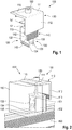
- Fig. 1 shows an embodiment of a height-adjustable end holder 100 according to the first aspect of the invention.
- the end holder 100 has a receiving angle element 110 and a fastening element 120 and an adjusting element 150.
- the adjusting element 150 is formed in the present embodiment as a screw.
- the adjusting element is designed to generate a contact pressure on the solar module to be mounted in an assembled state, not shown here, at an adjustable distance of the receptacle 115 from the mounting rail via the receptacle 115.
- the receiving angle element 110 is formed by a first receiving leg 111 and a second receiving leg 112. At the first receiving leg 111, a receptacle 115 is formed for a solar module to be mounted. Furthermore, the first receiving leg 111 has a bore for receiving the adjusting element 150.
- a first sawtooth profile 113 is arranged on its side facing the first receiving leg 111 side.
- the fastening element 120 has a clip holder 130 and a fastening angle element 140.
- the fastening angle element 140 is formed by a first fastening leg 141 and a second fastening leg 142.
- the first mounting leg 141, as well as the first receiving leg 111 has a bore (not visible here) for receiving the adjusting element.
- a second sawtooth profile 143 is arranged on its side facing the second receiving leg 112.
- the clip holder 130 has a head plate 131 with a threaded bore for receiving the adjusting element 150 and two laterally on the top plate 131 oppositely arranged Kliphalterschenkel 132, 133, whose remote from the top plate hooks 134, 135 which are formed to engage behind cranks ,
- the receiving angle element 110 is fastened in a height-adjustable manner by the adjusting element 150 on the fastening element 120.
- the first sawtooth profile 113 and the second sawtooth profile 143 are designed such that in a mounted state, not shown, under the contact pressure of the adjustment element 150, a relative movement of the receiving angle element 110 and the fastening element 120 to each other in a height direction perpendicular to a longitudinal direction of the rail, is blocked, and in the non-assembled state shown here, a relative movement of the receiving angle element 110 and the fastener 120 to each other in the height direction is possible.
- Fig. 2 shows an embodiment of a fastening system 200 according to the second aspect of the invention with an end holder 100 of the Fig. 1 illustrated embodiment in a perspective view.
- the fastening system 200 includes an end holder 100 that is attached to a rail 190.
- the solar module 180 to be mounted is symbolized here by a transparent cuboid.
- the receptacle 115 of the end holder attached to the first receiving leg 111 receives the solar module 180 and, by tightening the adjusting element 150 designed as a screw, a contact pressure on the profile rail is realized.
- the clip holder 130 engages here in the assembled state with the hooks 134, 135 which are formed on the Kliphalterschenkeln 132, 133, in the rail 190 and thus provides an easy-to-handle attachment to the rail 190.
- the top plate 131 of the clip holder 130 points a threaded bore into which the adjusting element 150 is received.
- the first sawtooth profile 113 is formed in the embodiment shown here only over a part of the length of the second receiving leg 112. Alternatively, in an embodiment not shown here, the execution of the sawtooth profile 113 over the entire length of the second receiving leg 112 is possible.
- Fig. 3 schematically shows how different module heights can be realized with a height-adjustable end holder 100 according to the first aspect of the invention in a fastening system.
- the module 181 has a module height of about 50 mm and the module 182 has a module height of about 30 mm.
- the different heights h1 and h2, which the receptacle 115 has over the profiled rail 190, are realized by means of the relative movement of the receptacle angle element 110 and of the fastening element 120 relative to one another.
- the adjusting element 150 ensures that in the assembled state, a contact pressure prevails, so that the sawtooth profiles 143 and 113 can no longer be moved against each other.
- the second receiving leg 112 of the receiving angle element 110 together with the second fastening leg 142, predetermines the stop heights h1 and h2 by the overlapping receiving legs 112 and the fastening leg 142 set via the adjusting element 150.
Landscapes
- Engineering & Computer Science (AREA)
- General Engineering & Computer Science (AREA)
- Mechanical Engineering (AREA)
- Structural Engineering (AREA)
- Civil Engineering (AREA)
- Architecture (AREA)
- Sustainable Development (AREA)
- Combustion & Propulsion (AREA)
- Chemical & Material Sciences (AREA)
- Thermal Sciences (AREA)
- Sustainable Energy (AREA)
- Physics & Mathematics (AREA)
- Life Sciences & Earth Sciences (AREA)
- Roof Covering Using Slabs Or Stiff Sheets (AREA)
- Photovoltaic Devices (AREA)
Description
- Die Erfindung betrifft einen Endhalter sowie ein Befestigungssystem zur Montage von Solarmodulen.
- Solarmodule, beispielsweise Photovoltaikmodule zur Erzeugung elektrischer Energie oder Kollektormodule zur Erwärmung von Wärmeträgermedien, werden üblicherweise in Dach- oder Freilandmontage auf parallel zueinander angeordneten Profilschienen befestigt. Es existiert eine Vielzahl von Solarmodulen, die sich hinsichtlich ihrer Abmessungen und Anordnungsmöglichkeiten unterscheiden. Unterschiedliche Typen von Solarmodulen weisen dabei unterschiedliche Modulhöhen auf. Dies betrifft insbesondere gerahmte Solarmodule. Montagesysteme für Solarmodule sollten daher möglichst variabel einsetzbar sein und eine schnelle und einfache Montage ermöglichen.
- Aus
DE 20 2013 005 668 ist ein höhenverstellbarer Endhalter bekannt, der mit Hilfe seines Höhenstellelementes so justiert werden kann, dass er für Module unterschiedlicher Höhe verwendet werden kann. Die hierfür nötige Höhenverstellung erfolgt stufenweise. AusDE 20 2011 107 843 ist ein höhenverstellbarer Endhalter mit den Merkmalen des Oberbegriffs des Anspruchs 1 bekannt. Ein erster Aspekt der vorliegenden Erfindung betrifft einen höhenverstellbaren Endhalter zur Befestigung von Solarmodulen unterschiedlicher Höhe an einer Profilschiene, mit - einem von einem ersten und einem zweiten Aufnahmeschenkel gebildeten Aufnahmewinkelelement, wobei am ersten Aufnahmeschenkel eine Aufnahme für ein zu montierendes Solarmodul ausgebildet ist,
- einem Befestigungselement zur Befestigung an einer Profilschiene,
- einem Verstellelement, das das Aufnahmewinkelelement am Befestigungselement höhenverstellbar befestigt und ausgebildet ist, in einem montierten Zustand bei einem einstellbaren Abstand der Aufnahme von der Profilschiene über die Aufnahme einen Anpressdruck auf das zu montierende Solarmodul zu erzeugen, wobei
- der zweite Aufnahmeschenkel auf seiner dem ersten Aufnahmeschenkel zugewandten Seite ein erstes Sägezahnprofil aufweist,
- das Befestigungselement an seiner dem zweiten Aufnahmeschenkel zugewandten Seite ein zweites Sägezahnprofil aufweist,
- wobei das erste Sägezahnprofil und das zweite Sägezahnprofil derart ausgebildet sind, dass im montierten Zustand unter dem Anpressdruck des Verstellelements eine Relativbewegung des Aufnahmewinkelelementes und des Befestigungselementes zueinander in einer Höhenrichtung, die senkrecht zu einer Längsrichtung der Profilschiene steht, blockiert ist, und in einem nicht-montierten Zustand eine Relativbewegung des Aufnahmewinkelelementes und des Befestigungselementes zueinander in der Höhenrichtung möglich ist, wobei das Befestigungselement aufweist:
- einen Kliphalter mit einer Kopfplatte mit einer Gewindebohrung sowie zwei seitlich an der Kopfplatte einander gegenüberliegend angeordnete Kliphalterschenkel, deren von der Kopfplatte abgewandte Enden Haken aufweisen, die ausgebildet sind, Kröpfungen zu hintergreifen und
- ein von einem ersten und einem zweiten Befestigungsschenkel gebildetes Befestigungswinkelelement, wobei das zweite Sägezahnprofil am zweiten Befestigungsschenkel ausgebildet ist und wobei
- Die Erfindung ermöglicht es, Einstellungen unterschiedlicher Höhen der Aufnahme des Endhalters über zwei einander zugewandte Sägezahnprofile an einem Aufnahmewinkelelement und einem Befestigungselement einzustellen. Diese Lösung weist den Vorteil auf, dass sie eine besonders einfach handhabbare, quasi stufenlose und somit besonders genaue Höheneinstellung erlaubt. Gleichzeitig bieten die Sägezahnprofile eine besonders sichere Einstellung der gewünschten Höhe im montierten Zustand. Die vorliegende Erfindung erzielt damit den Vorteil, ein verbessertes Montagesystem sowie einen vereinfachten Endhalter bereitzustellen, der variabel für unterschiedliche Modulhöhen einsetzbar ist. Beim Endhalter gemäß der vorliegenden Erfindung kann die Höhe über die Verschiebung des Befestigungselementes und des Aufnahmewinkelelementes zueinander im nicht montierten Zustand voreingestellt werden und mit Hilfe des Verstellelementes im Montagezustand feinjustiert werden. Damit ist eine einfache Montage unterschiedlicher Module möglich.
- Der Abstand der Aufnahme des Endhalters von einer Profilschiene, auf der der Endhalter montiert wird, also die Höheneinstellung, ergibt sich beim erfindungsgemäßen Endhalter aus der Relativverschiebung des Befestigungswinkelelementes und des Aufnahmewinkelelementes zueinander. Durch die Verschiebung der Sägezahnprofile zueinander ist somit eine einfache Justage möglich. Die Höheneinstellung ist quasi stufenlos möglich, da der Abstand benachbarter Höheneinstellungen nur von der Breite eines einzelnen Sägezahns des Sägezahnprofils abhängt.
- Nachfolgend werden Ausführungsformen und bevorzugte Anwendungsfälle des höhenverstellbaren Endhalters beschrieben.
- In einer Ausführungsform, die nicht Teil der Erfindung ist, ist das Befestigungselement ein Kliphalter, mit einer Kopfplatte mit einer Gewindebohrung sowie zwei seitlich an der Kopfplatte einander gegenüberliegend angeordneten Kliphalterschenkeln, deren von der Kopfplatte abgewandte Enden Haken aufweisen, die ausgebildet sind, Kröpfungen zu hintergreifen, wobei sich das zweite Sägezahnprofil an Schmalseiten der Kliphalterschenkel sowie an einer zwischen den Kliphalterschenkeln liegenden Schmalseite der Kopfplatte erstreckt. Das Befestigungselement der Erfindung weist einen Kliphalter mit einer Kopfplatte mit einer Gewindebohrung sowie zwei seitlich an der Kopfplatte einander gegenüberliegend angeordnete Kliphalterschenkel auf, deren von der Kopfplatte abgewandte Enden Haken aufweisen, die ausgebildet sind, Kröpfungen zu hintergreifen und ein von einem ersten und einem zweiten Befestigungsschenkel gebildetes Befestigungswinkelelement, wobei das zweite Sägezahnprofil am zweiten Befestigungsschenkel ausgebildet ist. Das Befestigungswinkelelement ist über das Verstellelement am Kliphalter befestigt.
- Die Verwendung von Befestigungselementen, die einen Kliphalter umfassen ist vorteilhaft, da Kliphalter schnell und unkompliziert an Profilschienen befestigt werden können und so zu einer einfach handhabbaren Montage beitragen.
- In einer bevorzugten Ausführungsform ist das Verstellelement eine Schraube.
- Gemäß einem zweiten Aspekt betrifft die Erfindung ein Befestigungssystem, das mindestens einen erfindungsgemäßen Endhalter und mindestens eine Profilschiene umfasst, an der der Endhalter befestigt ist.
- Der Endhalter ist in einer Ausführungsform ausgebildet, Modul- oder Rahmenhöhen im Bereich von 30 bis 50 mm zu halten. Andere Modul- oder Rahmenhöhen sind ebenfalls realisierbar, und können durch Anpassung der Länge des Aufnahmewinkelelementes und des Befestigungselementes ermöglicht werden.
- Gemäß einer bevorzugten Anwendungsform des Endhalters, die einen zweiten Aspekt der Erfindung bildet, umfasst Befestigungssystem mindestens einen Endhalter gemäß dem ersten Aspekt der Erfindung oder einer seiner Ausführungsformen und mindestens eine Profilschiene, an der der Endhalter befestigt ist.
- In einer Ausführungsform des Befestigungssystems ist der Endhalter quer zur Profilschiene montiert. Das bedeutet, dass der zweite Aufnahmeschenkel im Montagezustand quer zur Profilschiene angeordnet ist. In einer weiteren Ausführungsform des Befestigungssystems ist der Endhalter parallel zur Profilschiene montiert.
- Weitere Merkmale und Vorteile werden bei Betrachtung der nachfolgend mit Bezug auf die Figuren beschriebenen Ausführungsbeispiele offensichtlich werden. Es zeigen
- Fig. 1
- eine Ausführungsform eines höhenverstellbaren Endhalters in einer perspektivischen Darstellung.
- Fig. 2
- eine Teilansicht einer Ausführungsform eines Befestigungssystems in einer perspektivischen Darstellung.
- Fig. 3
- schematisch unterschiedliche Höheneinstellungen einer Ausführungsform des höhenverstellbaren Endhalters in einem Befestigungssystem.
-
Fig. 1 zeigt eine Ausführungsform eines höhenverstellbaren Endhalters 100 gemäß dem ersten Aspekt der Erfindung. - Der Endhalter 100 weist ein Aufnahmewinkelelement 110 sowie ein Befestigungselement 120 und ein Verstellelement 150 auf. Das Verstellelement 150 ist in der vorliegenden Ausführungsform als Schraube ausgebildet. Das Verstellelement ist dabei ausgebildet, in einem hier nicht dargestellten montierten Zustand bei einem einstellbaren Abstand der Aufnahme 115 von der Profilschiene über die Aufnahme 115 einen Anpressdruck auf das zu montierende Solarmodul zu erzeugen. Das Aufnahmewinkelelement 110 wird von einem ersten Aufnahmeschenkel 111 und einem zweiten Aufnahmeschenkel 112 gebildet. Am ersten Aufnahmeschenkel 111 ist eine Aufnahme 115 für ein zu montierendes Solarmodul ausgebildet. Desweiteren weist der erste Aufnahmeschenkel 111 eine Bohrung zur Aufnahme des Verstellelementes 150 auf. Am zweiten Aufnahmeschenkel 112 ist auf seiner dem ersten Aufnahmeschenkel 111 zugewandten Seite ein erstes Sägezahnprofil 113 angeordnet. Das Befestigungselement 120 weist in der gezeigten Ausführungsform einen Kliphalter 130 und ein Befestigungswinkelelement 140 auf. Das Befestigungswinkelelement 140 wird von einem ersten Befestigungsschenkel 141 und einem zweiten Befestigungsschenkel 142 gebildet. Der erste Befestigungsschenkel 141 weist wie auch der erste Aufnahmeschenkel 111 eine Bohrung (hier nicht sichtbar) zur Aufnahme des Verstellelementes auf. Am zweiten Befestigungsschenkel 142 ist auf seiner dem zweiten Aufnahmeschenkel 112 zugewandten Seite ein zweites Sägezahnprofil 143 angeordnet. Der Kliphalter 130 weist eine Kopfplatte 131 auf mit einer Gewindebohrung zur Aufnahme des Verstellelementes 150 sowie zwei seitlich an der Kopfplatte 131 einander gegenüberliegend angeordnete Kliphalterschenkel 132, 133, deren von der Kopfplatte abgewandte Enden Haken 134, 135 aufweisen, die ausgebildet sind, Kröpfungen zu hintergreifen. Das Aufnahmewinkelelement 110 ist durch das Verstellelement 150 am Befestigungselement 120 höhenverstellbar befestigt. Das erste Sägezahnprofil 113 und das zweite Sägezahnprofil 143 sind derart ausgebildet, dass in einem hier nicht dargestellten montierten Zustand unter dem Anpressdruck des Verstellelements 150 eine Relativbewegung des Aufnahmewinkelelementes 110 und des Befestigungselementes 120 zueinander in einer Höhenrichtung, die senkrecht zu einer Längsrichtung der Profilschiene steht, blockiert ist, und in hier gezeigten nicht-montierten Zustand eine Relativbewegung des Aufnahmewinkelelementes 110 und des Befestigungselementes 120 zueinander in der Höhenrichtung möglich ist.
-
Fig. 2 zeigt eine Ausführungsform eines Befestigungssystems 200 gemäß dem zweiten Aspekt der Erfindung mit einem Endhalter 100 der inFig. 1 dargestellten Ausführungsform in einer perspektivischen Ansicht. Das Befestigungssystem 200 umfasst einen Endhalter 100, der an einer Profilschiene 190 befestigt ist. Das zu montierende Solarmodul 180 ist hier durch einen transparenten Quader symbolisiert. In dieser perspektivischen Ansicht ist zu erkennen, dass die am ersten Aufnahmeschenkel 111 angebrachte Aufnahme 115 des Endhalters das Solarmodul 180 aufnimmt und über das Anziehen des als Schraube ausgebildeten Verstellelementes 150 ein Anpressdruck auf die Profilschiene realisiert wird. Der Kliphalter 130 greift hier im montierten Zustand mit den Haken 134, 135, die an den Kliphalterschenkeln 132, 133 ausgebildet sind, in die Profilschiene 190 ein und sorgt so für eine einfach handhabbare Befestigung an der Profilschiene 190. Die Kopfplatte 131 des Kliphalters 130 weist eine Gewindebohrung auf, in die das Verstellelement 150 aufgenommen wird. Wie in dieser Ansicht zu erkennen ist, ist das erste Sägezahnprofil 113 in der hier gezeigten Ausführungsform nur über einen Teil der Länge des zweiten Aufnahmeschenkels 112 ausgebildet. Alternativ ist in einer hier nicht gezeigten Ausführungsform auch die Ausführung des Sägezahnprofils 113 über die vollständige Länge des zweiten Aufnahmeschenkels 112 möglich. - In
Fig. 3 ist schematisch gezeigt, wie unterschiedliche Modulhöhen mit einem höhenverstellbaren Endhalter 100 gemäß dem ersten Aspekt der Erfindung in einem Befestigungssystem realisiert werden können. In der gezeigten Ausführungsform weist das Modul 181 eine Modulhöhe von ca. 50 mm und das Modul 182 eine Modulhöhe von ca. 30 mm auf. Die unterschiedlichen Höhen h1 und h2, die die Aufnahme 115 über der Profilschiene 190 aufweist werden über die Relativbewegung des Aufnahmewinkelelementes 110 und des Befestigungselementes 120 zueinander realisiert. Das Verstellelement 150 sorgt dafür, dass im montierten Zustand ein Anpressdruck herrscht, so dass die Sägezahnprofile 143 und 113 nicht mehr gegeneinander verschoben werden können. Dabei gibt der zweite Aufnahmeschenkel 112 des Aufnahmewinkelelementes 110 zusammen mit dem zweiten Befestigungsschenkel 142 die Anschlagshöhen h1 und h2 durch die jeweils über das Verstellelement 150 eingestellte Überlappung Aufnahmeschenkel 112 und des Befestigungsschenkels 142 vor.
Claims (3)
- Höhenverstellbarer Endhalter (100) zur Befestigung von Solarmodulen unterschiedlicher Höhe an einer Profilschiene, mit- einem von einem ersten und einem zweiten Aufnahmeschenkel (111, 112) gebildeten Aufnahmewinkelelement (110), wobei am ersten Aufnahmeschenkel (111) eine Aufnahme (115) für ein zu montierendes Solarmodul ausgebildet ist,- einem Befestigungselement (120) zur Befestigung an einer Profilschiene,- einem Verstellelement (150), das das Aufnahmewinkelelement (110) am Befestigungselement (120) höhenverstellbar befestigt und ausgebildet ist, in einem montierten Zustand bei einem einstellbaren Abstand der Aufnahme (115) von der Profilschiene über die Aufnahme (115) einen Anpressdruck auf das zu montierende Solarmodul zu erzeugen, wobei- der zweite Aufnahmeschenkel (112) auf seiner dem ersten Aufnahmeschenkel (111) zugewandten Seite ein erstes Sägezahnprofil (113) aufweist,- das Befestigungselement (120) an seiner dem zweiten Aufnahmeschenkel zugewandten Seite ein zweites Sägezahnprofil (143) aufweist,- wobei das erste Sägezahnprofil (113) und das zweite Sägezahnprofil (143) derart ausgebildet sind, dass im montierten Zustand unter dem Anpressdruck des Verstellelements (150) eine Relativbewegung des Aufnahmewinkelelementes (110) und des Befestigungselementes (120) zueinander in einer Höhenrichtung, die senkrecht zu einer Längsrichtung der Profilschiene steht, blockiert ist, und in einem nicht-montierten Zustand eine Relativbewegung des Aufnahmewinkelelementes (110) und des Befestigungselementes (120) zueinander in der Höhenrichtung möglich ist, wobeidas Befestigungselement aufweist:- einen Kliphalter (130) mit einer Kopfplatte (131) mit einer Gewindebohrung sowie zwei seitlich an der Kopfplatte einander gegenüberliegend angeordnete Kliphalterschenkel (132,133), deren von der Kopfplatte abgewandte Enden Haken (134, 135) aufweisen, die ausgebildet sind, Kröpfungen zu hintergreifen dadurch gekennzeichnet, dass das Befestigungselement (120) aufweist:das Verstellelement (150) das Befestigungswinkelelement (140) am Kliphalter (130) befestigt- ein von einem ersten und einem zweiten Befestigungsschenkel (141, 142) gebildetes Befestigungswinkelelement (140), wobei das zweite Sägezahnprofil (143) am zweiten Befestigungsschenkel (142) ausgebildet ist und wobei
- Endhalter (100) nach Anspruch 1, bei dem das Verstellelement (150) eine Schraube ist.
- Befestigungssystem (200) umfassend mindestens einen Endhalter (100) nach einem der Ansprüche 1 bis 2 und mindestens eine Profilschiene (190), an der der Endhalter befestigt ist.
Applications Claiming Priority (1)
| Application Number | Priority Date | Filing Date | Title |
|---|---|---|---|
| DE202014009489.6U DE202014009489U1 (de) | 2014-11-26 | 2014-11-26 | Endhalter und Befestigungssystem zur Montage von Solarmodulen |
Publications (2)
| Publication Number | Publication Date |
|---|---|
| EP3040640A1 EP3040640A1 (de) | 2016-07-06 |
| EP3040640B1 true EP3040640B1 (de) | 2017-12-20 |
Family
ID=52131754
Family Applications (1)
| Application Number | Title | Priority Date | Filing Date |
|---|---|---|---|
| EP16152545.6A Active EP3040640B1 (de) | 2014-11-26 | 2016-01-25 | Endhalter und befestigungssystem zur montage von solarmodulen |
Country Status (5)
| Country | Link |
|---|---|
| US (1) | US20160233820A1 (de) |
| EP (1) | EP3040640B1 (de) |
| JP (1) | JP6661341B2 (de) |
| DE (1) | DE202014009489U1 (de) |
| ES (1) | ES2657194T3 (de) |
Cited By (5)
| Publication number | Priority date | Publication date | Assignee | Title |
|---|---|---|---|---|
| DE202022105355U1 (de) | 2022-09-23 | 2022-10-07 | Obo Bettermann Hungary Kft | Befestigungsklemme |
| EP4276382A1 (de) * | 2022-05-09 | 2023-11-15 | S:FLEX GmbH Hamburg | Montageelement, einlegeprofil und montagesystem |
| EP4343228A1 (de) | 2022-09-23 | 2024-03-27 | OBO Bettermann Hungary Kft. | Befestigungsklemme |
| DE202023100438U1 (de) | 2023-01-31 | 2024-05-02 | Obo Bettermann Hungary Kft | Befestigungsklemme |
| DE202023100439U1 (de) | 2023-01-31 | 2024-05-02 | Obo Bettermann Hungary Kft | Befestigungsklemme |
Families Citing this family (39)
| Publication number | Priority date | Publication date | Assignee | Title |
|---|---|---|---|---|
| US9611652B2 (en) | 2011-02-25 | 2017-04-04 | Dustin M. M. Haddock | Mounting device for building surfaces having elongated mounting slot |
| WO2013101597A1 (en) | 2011-12-29 | 2013-07-04 | Haddock Dustin M M | Mounting device for nail strip panels |
| AU2016228586A1 (en) * | 2015-03-11 | 2017-11-02 | Ecolibrium Solar, Inc. | Sloped roof solar panel mounting system |
| US10673373B2 (en) | 2016-02-12 | 2020-06-02 | Solarcity Corporation | Building integrated photovoltaic roofing assemblies and associated systems and methods |
| US9876463B2 (en) | 2016-04-15 | 2018-01-23 | Sunmodo Corporation | Adjustable end clamp for mounting solar panels to roofs |
| US10443896B2 (en) | 2016-07-29 | 2019-10-15 | Rmh Tech Llc | Trapezoidal rib mounting bracket with flexible legs |
| US10640980B2 (en) | 2016-10-31 | 2020-05-05 | Rmh Tech Llc | Metal panel electrical bonding clip |
| CN108123662B (zh) * | 2016-11-30 | 2023-04-07 | 首帆动力科技股份有限公司 | 一种移动支架 |
| SE541420C2 (en) | 2016-12-16 | 2019-09-24 | Vaelinge Innovation Ab | A set of decking boards provided with a connecting system |
| EP3596283B1 (de) * | 2017-03-16 | 2025-06-11 | Välinge Innovation AB | Plattensystem |
| WO2018204137A1 (en) * | 2017-05-01 | 2018-11-08 | Hubbell Incorporated | Universal bonding end clamp |
| US10211773B2 (en) | 2017-05-24 | 2019-02-19 | Sunmodo Corporation | Height-adjustable solar panel mounting device |
| PL3684984T3 (pl) * | 2017-09-21 | 2023-03-06 | Hilti Aktiengesellschaft | Łącznik |
| WO2019074956A1 (en) | 2017-10-09 | 2019-04-18 | Rmh Tech Llc | RAIL ASSEMBLY WITH REVERSIBLE LATERAL MOUNT ADAPTER FOR DIRECT AND INDIRECT MOUNTING APPLICATIONS |
| EP3769017B1 (de) | 2018-03-21 | 2026-07-29 | RMH Tech LLC | Pv-modul-montageanordnung mit klemm-/abstandsanordnung |
| AU2019397167B2 (en) | 2018-12-14 | 2023-04-06 | Rmh Tech Llc | Mounting device for nail strip panels |
| CN113272507B (zh) | 2019-01-08 | 2023-03-10 | 瓦林格创新股份有限公司 | 设有连接系统和相关连接装置的甲板系统 |
| US12292075B2 (en) | 2019-11-25 | 2025-05-06 | Pegasus Solar Inc | Twist-lock solar module clamp |
| US11377840B2 (en) | 2019-11-26 | 2022-07-05 | Pegasus Solar Inc. | One-piece bonding splice for rails |
| US10797634B1 (en) | 2019-11-27 | 2020-10-06 | Sunmodo Corporation | Height-adjustable rail-less solar panel mounting device for roofs |
| DE112021001674T5 (de) | 2020-03-16 | 2023-06-01 | Rmh Tech Llc | Befestigungsvorrichtung für ein Metalldach |
| KR102377186B1 (ko) * | 2020-05-29 | 2022-03-22 | 주식회사 아하 | 태양광 모듈용 체결구 |
| EP4179219A4 (de) | 2020-07-09 | 2024-07-17 | RMH Tech LLC | Montagesystem, vorrichtung und verfahren |
| US11949369B2 (en) * | 2020-08-20 | 2024-04-02 | Unirac Inc. | Clamp apparatuses and components thereof for mounting solar panel modules |
| WO2023039155A1 (en) | 2021-09-09 | 2023-03-16 | Rmh Tech Llc | Torque actuated rail assembly |
| US12281750B2 (en) | 2022-01-14 | 2025-04-22 | Pegasus Solar Inc | Grip rail clamp |
| EP4551828A1 (de) | 2022-07-06 | 2025-05-14 | RMH Tech LLC | Montageanordnung für pv-modul mit klemm-/abstandsanordnung |
| USD1075493S1 (en) | 2022-07-06 | 2025-05-20 | Rmh Tech Llc | Clamp for a photovoltaic module mounting assembly |
| AU2023372054A1 (en) * | 2022-11-03 | 2025-03-06 | Pegasus Solar Inc | Module coupling clamp |
| US20240322749A1 (en) * | 2023-03-20 | 2024-09-26 | Greenec Corp. | Rail fixing assembly |
| AU2024255300A1 (en) | 2023-04-14 | 2025-11-20 | Rmh Tech Llc | Mounting device for a metal panel |
| USD1113406S1 (en) | 2023-04-14 | 2026-02-17 | Rmh Tech Llc | Mounting device |
| FR3148692B1 (fr) * | 2023-05-09 | 2025-06-06 | Caillau | Pièce pour la fixation d’un rail sur un profilé |
| USD1109686S1 (en) | 2023-08-10 | 2026-01-20 | Rmh Tech Llc | Mount for a component of a photovoltaic assembly |
| USD1128411S1 (en) | 2023-08-30 | 2026-06-02 | Rmh Tech Llc | Adjustable mounting bracket for attachment to a trapezoidal rib |
| USD1127727S1 (en) | 2023-09-07 | 2026-05-26 | Rmh Tech Llc | Mount for a component of a photovoltaic assembly |
| USD1134953S1 (en) | 2023-12-20 | 2026-07-14 | Rmh Tech Llc | Utility strut |
| CN117895873B (zh) * | 2024-03-12 | 2024-07-09 | 天合光能股份有限公司 | 快装压块 |
| DE202024107506U1 (de) * | 2024-12-20 | 2025-03-06 | VARISTA GmbH | Baugruppe einer Klemmvorrichtung, Klemmvorrichtung und Befestigungsanordnung |
Family Cites Families (7)
| Publication number | Priority date | Publication date | Assignee | Title |
|---|---|---|---|---|
| DE202009010487U1 (de) * | 2009-08-03 | 2009-12-10 | Schletter Gmbh | Endklemme zur Befestigung gerahmter PV-Module |
| US20110260027A1 (en) * | 2010-04-23 | 2011-10-27 | Daetwyler-Clean Energy LLC | Solar panel mounting assembly with locking cap |
| CN102263149A (zh) * | 2011-08-23 | 2011-11-30 | 山亿新能源股份有限公司 | 太阳能电池板的固定机构 |
| DE202011107843U1 (de) * | 2011-11-10 | 2011-11-28 | Creotecc Gmbh | Endklemmen für gerahmte Photovoltaikmodule |
| DE202012006839U1 (de) * | 2012-07-17 | 2012-08-10 | Knubix Gmbh | Befestigungsklemme für Solarmodule |
| CN202839634U (zh) * | 2012-08-07 | 2013-03-27 | 苏州瑞得恩光能科技有限公司 | 高度可调的压块 |
| DE202013005668U1 (de) | 2013-06-18 | 2014-09-23 | Mounting Systems Gmbh | Universeller Endhalter zur Halterung von Solarmodulen |
-
2014
- 2014-11-26 DE DE202014009489.6U patent/DE202014009489U1/de not_active Expired - Lifetime
-
2015
- 2015-11-24 US US14/950,816 patent/US20160233820A1/en not_active Abandoned
- 2015-11-26 JP JP2015230296A patent/JP6661341B2/ja active Active
-
2016
- 2016-01-25 EP EP16152545.6A patent/EP3040640B1/de active Active
- 2016-01-25 ES ES16152545.6T patent/ES2657194T3/es active Active
Non-Patent Citations (1)
| Title |
|---|
| None * |
Cited By (9)
| Publication number | Priority date | Publication date | Assignee | Title |
|---|---|---|---|---|
| EP4276382A1 (de) * | 2022-05-09 | 2023-11-15 | S:FLEX GmbH Hamburg | Montageelement, einlegeprofil und montagesystem |
| DE202022105355U1 (de) | 2022-09-23 | 2022-10-07 | Obo Bettermann Hungary Kft | Befestigungsklemme |
| DE102022133944B3 (de) | 2022-09-23 | 2023-08-31 | Obo Bettermann Hungary Kft | Befestigungsklemme |
| DE202023100460U1 (de) | 2022-09-23 | 2024-01-19 | Obo Bettermann Hungary Kft | Befestigungsklemme |
| EP4343228A1 (de) | 2022-09-23 | 2024-03-27 | OBO Bettermann Hungary Kft. | Befestigungsklemme |
| EP4343227A1 (de) | 2022-09-23 | 2024-03-27 | OBO Bettermann Hungary Kft. | Befestigungsklemme |
| DE202023100438U1 (de) | 2023-01-31 | 2024-05-02 | Obo Bettermann Hungary Kft | Befestigungsklemme |
| DE202023100439U1 (de) | 2023-01-31 | 2024-05-02 | Obo Bettermann Hungary Kft | Befestigungsklemme |
| EP4411150A1 (de) | 2023-01-31 | 2024-08-07 | OBO Bettermann Hungary Kft. | Befestigungsklemme |
Also Published As
| Publication number | Publication date |
|---|---|
| JP6661341B2 (ja) | 2020-03-11 |
| DE202014009489U1 (de) | 2014-12-12 |
| JP2016118091A (ja) | 2016-06-30 |
| ES2657194T3 (es) | 2018-03-01 |
| EP3040640A1 (de) | 2016-07-06 |
| US20160233820A1 (en) | 2016-08-11 |
Similar Documents
| Publication | Publication Date | Title |
|---|---|---|
| EP3040640A1 (de) | Endhalter und befestigungssystem zur montage von solarmodulen | |
| EP2009293B1 (de) | Vorrichtung zum Verbinden einer Profilschiene mit einem anderen Bauteil | |
| EP2435768B1 (de) | Vorrichtung zur befestigung einer montageschiene an einem gewindeschaft | |
| DE102011050856B4 (de) | System zum Befestigen von Solarmodulen | |
| DE202013005668U1 (de) | Universeller Endhalter zur Halterung von Solarmodulen | |
| WO2013143517A2 (de) | Freilandgestellsystem | |
| DE202015102936U1 (de) | Photovoltaikmodul-Montagebügel sowie Photovoltaiksystem | |
| EP3623721B1 (de) | Dachhaken | |
| EP3623722B1 (de) | Dachhaken | |
| DE102007018212B4 (de) | Befestigungseinrichtung für an einem Gestellaufbau anzuordnende Rahmenbauteile, insbesondere Solarmodule | |
| DE202012104033U1 (de) | Haltevorrichtung für eine Brüstungs- oder Geländerplatte sowie Geländer oder Brüstung mit Scheibe | |
| EP3043123A1 (de) | Mehrteiliger dachhaken und befestigungssystem | |
| WO2014169396A1 (de) | Tragstruktur zur befestigung eines solarmoduls auf eimem gebäudedach oder an einer gebäudefassade | |
| EP3325897A1 (de) | Vorrichtung zum befestigen von pv-modulen an profilen | |
| DE202010012937U1 (de) | Befestigungssystem | |
| DE202010008389U1 (de) | Vorrichtung zum Befestigen einer Tragschiene | |
| DE20205349U1 (de) | Befestigungsvorrichtung für Sonnenkollektoren | |
| EP3071896B1 (de) | Haltevorrichtung für ein gehäuse und verfahren zur montage des gehäuses unter verwendung der haltevorrichtung | |
| EP2682681B1 (de) | Befestigungseinrichtung zur Festlegung eines Heiz- oder Kühlkörpers | |
| DE102013109883B4 (de) | Schraubverbindung | |
| DE29920643U1 (de) | Klemmhalter für die Befestigung eines Röhrenradiators | |
| EP4411276A2 (de) | Montagesystem | |
| DE202013004877U1 (de) | Teleskophalterung für Solarmodule | |
| DE102013018419A1 (de) | Solarmodulträgersystem | |
| DE202007008150U1 (de) | Befestigungsvorrichtung für Solarmodule |
Legal Events
| Date | Code | Title | Description |
|---|---|---|---|
| PUAI | Public reference made under article 153(3) epc to a published international application that has entered the european phase |
Free format text: ORIGINAL CODE: 0009012 |
|
| AK | Designated contracting states |
Kind code of ref document: A1 Designated state(s): AL AT BE BG CH CY CZ DE DK EE ES FI FR GB GR HR HU IE IS IT LI LT LU LV MC MK MT NL NO PL PT RO RS SE SI SK SM TR |
|
| AX | Request for extension of the european patent |
Extension state: BA ME |
|
| 17P | Request for examination filed |
Effective date: 20170109 |
|
| RBV | Designated contracting states (corrected) |
Designated state(s): AL AT BE BG CH CY CZ DE DK EE ES FI FR GB GR HR HU IE IS IT LI LT LU LV MC MK MT NL NO PL PT RO RS SE SI SK SM TR |
|
| GRAP | Despatch of communication of intention to grant a patent |
Free format text: ORIGINAL CODE: EPIDOSNIGR1 |
|
| RIC1 | Information provided on ipc code assigned before grant |
Ipc: F24J 2/52 20060101AFI20170522BHEP |
|
| INTG | Intention to grant announced |
Effective date: 20170626 |
|
| GRAS | Grant fee paid |
Free format text: ORIGINAL CODE: EPIDOSNIGR3 |
|
| GRAJ | Information related to disapproval of communication of intention to grant by the applicant or resumption of examination proceedings by the epo deleted |
Free format text: ORIGINAL CODE: EPIDOSDIGR1 |
|
| GRAL | Information related to payment of fee for publishing/printing deleted |
Free format text: ORIGINAL CODE: EPIDOSDIGR3 |
|
| GRAR | Information related to intention to grant a patent recorded |
Free format text: ORIGINAL CODE: EPIDOSNIGR71 |
|
| GRAA | (expected) grant |
Free format text: ORIGINAL CODE: 0009210 |
|
| INTC | Intention to grant announced (deleted) | ||
| AK | Designated contracting states |
Kind code of ref document: B1 Designated state(s): AL AT BE BG CH CY CZ DE DK EE ES FI FR GB GR HR HU IE IS IT LI LT LU LV MC MK MT NL NO PL PT RO RS SE SI SK SM TR |
|
| INTG | Intention to grant announced |
Effective date: 20171115 |
|
| REG | Reference to a national code |
Ref country code: GB Ref legal event code: FG4D Free format text: NOT ENGLISH |
|
| REG | Reference to a national code |
Ref country code: CH Ref legal event code: EP Ref country code: CH Ref legal event code: NV Representative=s name: KELLER AND PARTNER PATENTANWAELTE AG, CH |
|
| REG | Reference to a national code |
Ref country code: IE Ref legal event code: FG4D Free format text: LANGUAGE OF EP DOCUMENT: GERMAN |
|
| REG | Reference to a national code |
Ref country code: AT Ref legal event code: REF Ref document number: 956730 Country of ref document: AT Kind code of ref document: T Effective date: 20180115 |
|
| REG | Reference to a national code |
Ref country code: DE Ref legal event code: R096 Ref document number: 502016000362 Country of ref document: DE |
|
| REG | Reference to a national code |
Ref country code: FR Ref legal event code: PLFP Year of fee payment: 3 |
|
| REG | Reference to a national code |
Ref country code: ES Ref legal event code: FG2A Ref document number: 2657194 Country of ref document: ES Kind code of ref document: T3 Effective date: 20180301 |
|
| REG | Reference to a national code |
Ref country code: NL Ref legal event code: FP |
|
| PG25 | Lapsed in a contracting state [announced via postgrant information from national office to epo] |
Ref country code: SE Free format text: LAPSE BECAUSE OF FAILURE TO SUBMIT A TRANSLATION OF THE DESCRIPTION OR TO PAY THE FEE WITHIN THE PRESCRIBED TIME-LIMIT Effective date: 20171220 Ref country code: NO Free format text: LAPSE BECAUSE OF FAILURE TO SUBMIT A TRANSLATION OF THE DESCRIPTION OR TO PAY THE FEE WITHIN THE PRESCRIBED TIME-LIMIT Effective date: 20180320 Ref country code: LT Free format text: LAPSE BECAUSE OF FAILURE TO SUBMIT A TRANSLATION OF THE DESCRIPTION OR TO PAY THE FEE WITHIN THE PRESCRIBED TIME-LIMIT Effective date: 20171220 Ref country code: FI Free format text: LAPSE BECAUSE OF FAILURE TO SUBMIT A TRANSLATION OF THE DESCRIPTION OR TO PAY THE FEE WITHIN THE PRESCRIBED TIME-LIMIT Effective date: 20171220 |
|
| REG | Reference to a national code |
Ref country code: DE Ref legal event code: R082 Ref document number: 502016000362 Country of ref document: DE Representative=s name: BOEHMERT & BOEHMERT ANWALTSPARTNERSCHAFT MBB -, DE Ref country code: DE Ref legal event code: R082 Ref document number: 502016000362 Country of ref document: DE Representative=s name: KOHLER SCHMID MOEBUS PATENTANWAELTE PARTNERSCH, DE |
|
| REG | Reference to a national code |
Ref country code: LT Ref legal event code: MG4D |
|
| PG25 | Lapsed in a contracting state [announced via postgrant information from national office to epo] |
Ref country code: GR Free format text: LAPSE BECAUSE OF FAILURE TO SUBMIT A TRANSLATION OF THE DESCRIPTION OR TO PAY THE FEE WITHIN THE PRESCRIBED TIME-LIMIT Effective date: 20180321 Ref country code: HR Free format text: LAPSE BECAUSE OF FAILURE TO SUBMIT A TRANSLATION OF THE DESCRIPTION OR TO PAY THE FEE WITHIN THE PRESCRIBED TIME-LIMIT Effective date: 20171220 Ref country code: BG Free format text: LAPSE BECAUSE OF FAILURE TO SUBMIT A TRANSLATION OF THE DESCRIPTION OR TO PAY THE FEE WITHIN THE PRESCRIBED TIME-LIMIT Effective date: 20180320 Ref country code: RS Free format text: LAPSE BECAUSE OF FAILURE TO SUBMIT A TRANSLATION OF THE DESCRIPTION OR TO PAY THE FEE WITHIN THE PRESCRIBED TIME-LIMIT Effective date: 20171220 Ref country code: LV Free format text: LAPSE BECAUSE OF FAILURE TO SUBMIT A TRANSLATION OF THE DESCRIPTION OR TO PAY THE FEE WITHIN THE PRESCRIBED TIME-LIMIT Effective date: 20171220 |
|
| REG | Reference to a national code |
Ref country code: DE Ref legal event code: R082 Ref document number: 502016000362 Country of ref document: DE Representative=s name: KOHLER SCHMID MOEBUS PATENTANWAELTE PARTNERSCH, DE |
|
| PG25 | Lapsed in a contracting state [announced via postgrant information from national office to epo] |
Ref country code: CZ Free format text: LAPSE BECAUSE OF FAILURE TO SUBMIT A TRANSLATION OF THE DESCRIPTION OR TO PAY THE FEE WITHIN THE PRESCRIBED TIME-LIMIT Effective date: 20171220 Ref country code: SK Free format text: LAPSE BECAUSE OF FAILURE TO SUBMIT A TRANSLATION OF THE DESCRIPTION OR TO PAY THE FEE WITHIN THE PRESCRIBED TIME-LIMIT Effective date: 20171220 Ref country code: CY Free format text: LAPSE BECAUSE OF FAILURE TO SUBMIT A TRANSLATION OF THE DESCRIPTION OR TO PAY THE FEE WITHIN THE PRESCRIBED TIME-LIMIT Effective date: 20171220 Ref country code: EE Free format text: LAPSE BECAUSE OF FAILURE TO SUBMIT A TRANSLATION OF THE DESCRIPTION OR TO PAY THE FEE WITHIN THE PRESCRIBED TIME-LIMIT Effective date: 20171220 |
|
| PG25 | Lapsed in a contracting state [announced via postgrant information from national office to epo] |
Ref country code: RO Free format text: LAPSE BECAUSE OF FAILURE TO SUBMIT A TRANSLATION OF THE DESCRIPTION OR TO PAY THE FEE WITHIN THE PRESCRIBED TIME-LIMIT Effective date: 20171220 Ref country code: IS Free format text: LAPSE BECAUSE OF FAILURE TO SUBMIT A TRANSLATION OF THE DESCRIPTION OR TO PAY THE FEE WITHIN THE PRESCRIBED TIME-LIMIT Effective date: 20180420 Ref country code: PL Free format text: LAPSE BECAUSE OF FAILURE TO SUBMIT A TRANSLATION OF THE DESCRIPTION OR TO PAY THE FEE WITHIN THE PRESCRIBED TIME-LIMIT Effective date: 20171220 Ref country code: IT Free format text: LAPSE BECAUSE OF FAILURE TO SUBMIT A TRANSLATION OF THE DESCRIPTION OR TO PAY THE FEE WITHIN THE PRESCRIBED TIME-LIMIT Effective date: 20171220 Ref country code: SM Free format text: LAPSE BECAUSE OF FAILURE TO SUBMIT A TRANSLATION OF THE DESCRIPTION OR TO PAY THE FEE WITHIN THE PRESCRIBED TIME-LIMIT Effective date: 20171220 |
|
| REG | Reference to a national code |
Ref country code: DE Ref legal event code: R097 Ref document number: 502016000362 Country of ref document: DE |
|
| PG25 | Lapsed in a contracting state [announced via postgrant information from national office to epo] |
Ref country code: MC Free format text: LAPSE BECAUSE OF FAILURE TO SUBMIT A TRANSLATION OF THE DESCRIPTION OR TO PAY THE FEE WITHIN THE PRESCRIBED TIME-LIMIT Effective date: 20171220 Ref country code: MT Free format text: LAPSE BECAUSE OF FAILURE TO SUBMIT A TRANSLATION OF THE DESCRIPTION OR TO PAY THE FEE WITHIN THE PRESCRIBED TIME-LIMIT Effective date: 20171220 |
|
| PG25 | Lapsed in a contracting state [announced via postgrant information from national office to epo] |
Ref country code: LU Free format text: LAPSE BECAUSE OF NON-PAYMENT OF DUE FEES Effective date: 20180125 |
|
| REG | Reference to a national code |
Ref country code: IE Ref legal event code: MM4A |
|
| PLBE | No opposition filed within time limit |
Free format text: ORIGINAL CODE: 0009261 |
|
| STAA | Information on the status of an ep patent application or granted ep patent |
Free format text: STATUS: NO OPPOSITION FILED WITHIN TIME LIMIT |
|
| REG | Reference to a national code |
Ref country code: BE Ref legal event code: MM Effective date: 20180131 |
|
| PG25 | Lapsed in a contracting state [announced via postgrant information from national office to epo] |
Ref country code: BE Free format text: LAPSE BECAUSE OF NON-PAYMENT OF DUE FEES Effective date: 20180131 Ref country code: DK Free format text: LAPSE BECAUSE OF FAILURE TO SUBMIT A TRANSLATION OF THE DESCRIPTION OR TO PAY THE FEE WITHIN THE PRESCRIBED TIME-LIMIT Effective date: 20171220 |
|
| 26N | No opposition filed |
Effective date: 20180921 |
|
| PG25 | Lapsed in a contracting state [announced via postgrant information from national office to epo] |
Ref country code: IE Free format text: LAPSE BECAUSE OF NON-PAYMENT OF DUE FEES Effective date: 20180125 |
|
| PG25 | Lapsed in a contracting state [announced via postgrant information from national office to epo] |
Ref country code: SI Free format text: LAPSE BECAUSE OF FAILURE TO SUBMIT A TRANSLATION OF THE DESCRIPTION OR TO PAY THE FEE WITHIN THE PRESCRIBED TIME-LIMIT Effective date: 20171220 |
|
| PG25 | Lapsed in a contracting state [announced via postgrant information from national office to epo] |
Ref country code: TR Free format text: LAPSE BECAUSE OF FAILURE TO SUBMIT A TRANSLATION OF THE DESCRIPTION OR TO PAY THE FEE WITHIN THE PRESCRIBED TIME-LIMIT Effective date: 20171220 |
|
| PG25 | Lapsed in a contracting state [announced via postgrant information from national office to epo] |
Ref country code: PT Free format text: LAPSE BECAUSE OF FAILURE TO SUBMIT A TRANSLATION OF THE DESCRIPTION OR TO PAY THE FEE WITHIN THE PRESCRIBED TIME-LIMIT Effective date: 20171220 |
|
| PG25 | Lapsed in a contracting state [announced via postgrant information from national office to epo] |
Ref country code: MK Free format text: LAPSE BECAUSE OF NON-PAYMENT OF DUE FEES Effective date: 20171220 Ref country code: HU Free format text: LAPSE BECAUSE OF FAILURE TO SUBMIT A TRANSLATION OF THE DESCRIPTION OR TO PAY THE FEE WITHIN THE PRESCRIBED TIME-LIMIT; INVALID AB INITIO Effective date: 20160125 |
|
| PG25 | Lapsed in a contracting state [announced via postgrant information from national office to epo] |
Ref country code: AL Free format text: LAPSE BECAUSE OF FAILURE TO SUBMIT A TRANSLATION OF THE DESCRIPTION OR TO PAY THE FEE WITHIN THE PRESCRIBED TIME-LIMIT Effective date: 20171220 |
|
| REG | Reference to a national code |
Ref country code: CH Ref legal event code: PFA Owner name: MOUNTING SYSTEMS GMBH, DE Free format text: FORMER OWNER: MOUNTING SYSTEMS GMBH, DE |
|
| REG | Reference to a national code |
Ref country code: DE Ref legal event code: R082 Ref document number: 502016000362 Country of ref document: DE Representative=s name: BOEHMERT & BOEHMERT ANWALTSPARTNERSCHAFT MBB -, DE Ref country code: DE Ref legal event code: R082 Ref document number: 502016000362 Country of ref document: DE Representative=s name: DENNEMEYER & ASSOCIATES RECHTSANWALTSGESELLSCH, DE |
|
| REG | Reference to a national code |
Ref country code: CH Ref legal event code: U11 Free format text: ST27 STATUS EVENT CODE: U-0-0-U10-U11 (AS PROVIDED BY THE NATIONAL OFFICE) Effective date: 20260201 |
|
| PGFP | Annual fee paid to national office [announced via postgrant information from national office to epo] |
Ref country code: NL Payment date: 20260122 Year of fee payment: 11 |
|
| PGFP | Annual fee paid to national office [announced via postgrant information from national office to epo] |
Ref country code: GB Payment date: 20260126 Year of fee payment: 11 |
|
| PGFP | Annual fee paid to national office [announced via postgrant information from national office to epo] |
Ref country code: ES Payment date: 20260210 Year of fee payment: 11 |
|
| PGFP | Annual fee paid to national office [announced via postgrant information from national office to epo] |
Ref country code: DE Payment date: 20260127 Year of fee payment: 11 |
|
| PGFP | Annual fee paid to national office [announced via postgrant information from national office to epo] |
Ref country code: AT Payment date: 20260119 Year of fee payment: 11 |
|
| PGFP | Annual fee paid to national office [announced via postgrant information from national office to epo] |
Ref country code: FR Payment date: 20260126 Year of fee payment: 11 |
|
| PGFP | Annual fee paid to national office [announced via postgrant information from national office to epo] |
Ref country code: CH Payment date: 20260201 Year of fee payment: 11 |
|
| REG | Reference to a national code |
Ref country code: CH Ref legal event code: R14 Free format text: ST27 STATUS EVENT CODE: U-0-0-R10-R14 (AS PROVIDED BY THE NATIONAL OFFICE) Effective date: 20260619 Ref country code: CH Ref legal event code: R17 Free format text: ST27 STATUS EVENT CODE: U-0-0-R10-R17 (AS PROVIDED BY THE NATIONAL OFFICE) Effective date: 20260619 |
|
| REG | Reference to a national code |
Ref country code: DE Ref legal event code: R081 Ref document number: 502016000362 Country of ref document: DE Owner name: ADOLF WUERTH GMBH & CO. KG, DE Free format text: FORMER OWNER: MOUNTING SYSTEMS GMBH, 15834 RANGSDORF, DE Ref country code: DE Ref legal event code: R082 Ref document number: 502016000362 Country of ref document: DE Representative=s name: DENNEMEYER & ASSOCIATES RECHTSANWALTSGESELLSCH, DE |
|
| REG | Reference to a national code |
Ref country code: GB Ref legal event code: 732E Free format text: REGISTERED BETWEEN 20260625 AND 20260701 |