EP3050521B1 - Scie sagittale chirurgicale et lame complémentaire avec des caractéristiques qui retiennent solidement la lame statique sur la scie - Google Patents
Scie sagittale chirurgicale et lame complémentaire avec des caractéristiques qui retiennent solidement la lame statique sur la scie Download PDFInfo
- Publication number
- EP3050521B1 EP3050521B1 EP16000121.0A EP16000121A EP3050521B1 EP 3050521 B1 EP3050521 B1 EP 3050521B1 EP 16000121 A EP16000121 A EP 16000121A EP 3050521 B1 EP3050521 B1 EP 3050521B1
- Authority
- EP
- European Patent Office
- Prior art keywords
- blade
- pin
- head
- saw
- opening
- Prior art date
- Legal status (The legal status is an assumption and is not a legal conclusion. Google has not performed a legal analysis and makes no representation as to the accuracy of the status listed.)
- Not-in-force
Links
Images


Classifications
-
- A—HUMAN NECESSITIES
- A61—MEDICAL OR VETERINARY SCIENCE; HYGIENE
- A61B—DIAGNOSIS; SURGERY; IDENTIFICATION
- A61B17/00—Surgical instruments, devices or methods
- A61B17/16—Instruments for performing osteoclasis; Drills or chisels for bones; Trepans
- A61B17/1637—Hollow drills or saws producing a curved cut, e.g. cylindrical
-
- A—HUMAN NECESSITIES
- A61—MEDICAL OR VETERINARY SCIENCE; HYGIENE
- A61B—DIAGNOSIS; SURGERY; IDENTIFICATION
- A61B17/00—Surgical instruments, devices or methods
- A61B17/14—Surgical saws
- A61B17/142—Surgical saws with reciprocating saw blades, e.g. with cutting edges at the distal end of the saw blades
-
- A—HUMAN NECESSITIES
- A61—MEDICAL OR VETERINARY SCIENCE; HYGIENE
- A61F—FILTERS IMPLANTABLE INTO BLOOD VESSELS; PROSTHESES; DEVICES PROVIDING PATENCY TO, OR PREVENTING COLLAPSING OF, TUBULAR STRUCTURES OF THE BODY, e.g. STENTS; ORTHOPAEDIC, NURSING OR CONTRACEPTIVE DEVICES; FOMENTATION; TREATMENT OR PROTECTION OF EYES OR EARS; BANDAGES, DRESSINGS OR ABSORBENT PADS; FIRST-AID KITS
- A61F2/00—Filters implantable into blood vessels; Prostheses, i.e. artificial substitutes or replacements for parts of the body; Appliances for connecting them with the body; Devices providing patency to, or preventing collapsing of, tubular structures of the body, e.g. stents
- A61F2/02—Prostheses implantable into the body
- A61F2/30—Joints
- A61F2/46—Special tools for implanting artificial joints
- A61F2/4603—Special tools for implanting artificial joints for insertion or extraction of endoprosthetic joints or of accessories thereof
- A61F2/4609—Special tools for implanting artificial joints for insertion or extraction of endoprosthetic joints or of accessories thereof of acetabular cups
-
- B—PERFORMING OPERATIONS; TRANSPORTING
- B23—MACHINE TOOLS; METAL-WORKING NOT OTHERWISE PROVIDED FOR
- B23D—PLANING; SLOTTING; SHEARING; BROACHING; SAWING; FILING; SCRAPING; LIKE OPERATIONS FOR WORKING METAL BY REMOVING MATERIAL, NOT OTHERWISE PROVIDED FOR
- B23D51/00—Sawing machines or sawing devices working with straight blades, characterised only by constructional features of particular parts; Carrying or attaching means for tools, covered by this subclass, which are connected to a carrier at both ends
- B23D51/08—Sawing machines or sawing devices working with straight blades, characterised only by constructional features of particular parts; Carrying or attaching means for tools, covered by this subclass, which are connected to a carrier at both ends of devices for mounting straight saw blades or other tools
- B23D51/10—Sawing machines or sawing devices working with straight blades, characterised only by constructional features of particular parts; Carrying or attaching means for tools, covered by this subclass, which are connected to a carrier at both ends of devices for mounting straight saw blades or other tools for hand-held or hand-operated devices
-
- B—PERFORMING OPERATIONS; TRANSPORTING
- B23—MACHINE TOOLS; METAL-WORKING NOT OTHERWISE PROVIDED FOR
- B23D—PLANING; SLOTTING; SHEARING; BROACHING; SAWING; FILING; SCRAPING; LIKE OPERATIONS FOR WORKING METAL BY REMOVING MATERIAL, NOT OTHERWISE PROVIDED FOR
- B23D61/00—Tools for sawing machines or sawing devices; Clamping devices for these tools
- B23D61/006—Oscillating saw blades
-
- A—HUMAN NECESSITIES
- A61—MEDICAL OR VETERINARY SCIENCE; HYGIENE
- A61F—FILTERS IMPLANTABLE INTO BLOOD VESSELS; PROSTHESES; DEVICES PROVIDING PATENCY TO, OR PREVENTING COLLAPSING OF, TUBULAR STRUCTURES OF THE BODY, e.g. STENTS; ORTHOPAEDIC, NURSING OR CONTRACEPTIVE DEVICES; FOMENTATION; TREATMENT OR PROTECTION OF EYES OR EARS; BANDAGES, DRESSINGS OR ABSORBENT PADS; FIRST-AID KITS
- A61F2/00—Filters implantable into blood vessels; Prostheses, i.e. artificial substitutes or replacements for parts of the body; Appliances for connecting them with the body; Devices providing patency to, or preventing collapsing of, tubular structures of the body, e.g. stents
- A61F2/02—Prostheses implantable into the body
- A61F2/30—Joints
- A61F2/46—Special tools for implanting artificial joints
- A61F2/4603—Special tools for implanting artificial joints for insertion or extraction of endoprosthetic joints or of accessories thereof
- A61F2002/4619—Special tools for implanting artificial joints for insertion or extraction of endoprosthetic joints or of accessories thereof for extraction
Definitions
- This invention generally relates to surgical sagittal saws and the complementary blades used with the sagittal saws.
- the invention relates to a saw and blade with complementary features that facilitate holding the blade static to the saw at a fixed location relative to the saw.
- a powered surgical instrument, surgical tool, used with some frequency is the powered surgical saw.
- This type of instrument is used to remove tissue, including bone and cartilage.
- Attached to the saw is a saw blade.
- a drive assembly internal to the saw reciprocates the blade in a back and forth motion.
- the saw includes a moving head. The head is the component of the saw to which the blade is mounted.
- Some blades are constructed to pivot back and forth, oscillate, in the plane in which the blade is oriented. This type of blade is referred to as a sagittal saw blade.
- a sagittal saw blade is provided with teeth that extend forward from the distal end of the blade body.
- a species of the sagittal saw is the acetabular cup remover. As implied by its name, this type of surgical power instrument is used to remove an artificial acetabular cup.
- An artificial acetabular cup is sometimes implanted in a patient during hip replacement surgery. Hip replacement surgery consists of the replacement of the existing ball and socket of the hip joint with prosthetic replacements. The head of the femur, the ball, is typically removed and replaced with a femoral component made of biocompatible material. This component mirrors the structure of the original bone. The acetabulum, the socket in the hip, is often reamed to form a hole. An artificial acetabular cup that corresponds and cooperates with the femoral component is fitted in the hole.
- This artificial acetabular cup often includes an outer shell constructed of a metallic material. Typically this shell is in the form of a hollowed out semi-sphere. An insert, constructed of plastic, ceramic or metal, is seated in the outer shell. In many cases, the acetabular cup component is anchored in the bone with cement. Some cups are press fit in place. Still other cups are held in place by screws or fastening tabs integral with the cup itself. A combination of these fastening methods may be employed. Sometimes, owing to the shape of the outer shell and/or the application of compound that enhance bone growth, the outer shell is designed to foster the growth of bone adjacent the shell. This new bone anchors the cup to the rest of the hip. Total hip replacement surgery has often proven successful in relieving many problems associated with the hip joint.
- Total hip replacement surgery is often successful. Nevertheless, it is sometimes necessary to perform the same surgery on the same hip. This may be necessary in situations in which wear or infection degrade the performance of the installed cup and femoral head. This sub-set of total hip replacement surgery is sometimes called revision surgery. In a revision surgery, it is necessary to remove the acetabular cup previously implanted in the hip. As mentioned above, these components may have been cemented in place or otherwise held by bone or fibrous tissue that may have grown in and around the component. Thus, their removal requires the cutting or chipping away of cement or bone material.
- the acetabular cup remover is employed to remove the artificial acetabular cup.
- This type of saw includes a pivot head that seats in the socket of the cup. A saw head is connected to the pivot head.
- the complementary blade has a foot that projects outwardly from the head.
- the blade has a trunk, a main body that, relative to the foot, extends downwardly. More particularly, the trunk is shaped to curve around the outer surface of the cup the saw is employed to remove. Teeth extend outwardly from the end and sometimes the side of the trunk.
- the saw head is oscillated to cause a similar back and forth motion of the blade. The blade is then driven around the outer surface of the cup.
- a surgical sagittal saw includes an assembly for removably holding the blade to the saw head. This is because the blade, to ensure sterility is removed and replaced between surgeries on different patients. Often a new blade is used for each surgery. This is because upon use of the blade, the teeth are immediately dulled. Owing to the economics, it is often more cost effective to use a new blade with each patient than go to the expense of sterilizing and resharpening a previously used blade. This means that, each time a saw or acetabular cup remover is used for a new patient, a new blade is fitted to the saw. Moreover, during the process of removing an acetabular cup, often two or more blades are used in sequence.
- the first blade has a trunk that subtends a first arc. This blade is used to form an initial shallow cut around the acetabular cup being removed. Once this shallow cut is formed, a second blade is fitted to the acetabular cup remover. This second blade subtends an arc greater than that subtended by the first blade. The second blade is used to form a deeper cut. This deeper cut typically extends completely around the cup. Once this deep cut is formed, the cup is then removed from the hip.
- a surgical sagittal saw including a saw designed as an acetabular cup remover, is typically designed so that the head has a slot.
- the slot is the void space dimensioned to receive the proximal end of the blade.
- the proximal end of the blade is provided with one or more openings. Each opening is dimensioned to receive a pin that is moveably mounted to the saw head. The seating of the pin in the blade opening re-leasably holds the blade to the head.
- the back-and-forth movement of the blade is not always in phase with the back-and-forth movement of the saw head. More specifically this occurs because when the saw head reverses direction, owing to the blade having a momentum in the opposite direction, the blade continues to move in the first direction. Thus, there may be times in the movement of the saw head and blade where these two components move in the opposed directions. This can result in the blade striking an adjacent surface of the saw head. This action is sometimes referred to as blade slap.
- a result of blades continually slapping against the saw head is that the material forming the head can fatigue. This component fatigue can result in the fracturing of the saw head. Once such a fracture occurs, at a minimum, it is necessary to replace the saw head.
- a resection guide is a block that is affixed to the bone adjacent where the cut is to be formed.
- the block is formed with one or more slots.
- the slots serve as guide paths through which the saw blade is inserted.
- the surgeon shapes the remaining bone to have a selected, precisely defined shape.
- This precision shaping of the bone is often performed to ensure the proper fitting of an orthopedic implant to the bone. Owing to the flexure of the blade when fitted in one of these slots, the blade can gall, wear the material that defines the slots. This can result in the shape of the slot deforming from the shape needed to ensure that a cut formed based on the shape of the slot has the desired shape. Once this deformation of the resection guide occurs, the guide is no longer useful.
- This blade shifting is also disadvantageous when it occurs relative to the head of an acetabular cup remover.
- the acetabular cup remover is designed so that when the blade is fitted to the saw, and the blade moved around the cup being removed, the blade ideally should move as close as possible around the cup without pressing against the cup. If the blade is spaced away from the cup, more bone is removed from the patient than is necessary to remove the acetabular cup. This can complicate the process of fitting the replacement cup. If the blade presses against the acetabular cup the metal-against-metal movement of the blade, at a minimum, reduces the efficiency of the bone removal process. A more adverse result from this contact is the deformation of the blade or the cup. Either of these events can appreciably complicate the removal of the old cup and the fitting of the replacement cup.
- An alternative means to ensure the saw head and blade move as a single rigid body is to provide a clamping assembly that, when set, applies an appreciable amount of force to the blade to hold the blade to the saw head.
- Document US 2014/018811 A1 describes a saw, comprising a drive, a first blade configured to oscillate about an axis perpendicular to a plane defined by a surface of the first blade, and a second blade configured to oscillate about an axis perpendicular to the plane in a direction opposite to that of the first blade. Gearing is provided between the drive and the first and second blades to reduce the speed transmitted from the drive to the blades.
- a saw blade, a connection mechanism for connecting a blade to a saw and associated methods are also provided.
- Document US 2005/192585 shows a motor assembly, a collet assembly connected to the motor assembly, and a dissection tool such as a bone saw blade.
- the collet assembly includes a body portion with a plurality of engaging members.
- the dissection tool includes a tool body with a hub positioned in an opening formed within the tool body.
- the hub includes a plurality of indentions configured to selectively engage with the engaging members.
- This invention relates to a new and useful surgical saw with a coupling assembly that firmly, yet releasably, holds the complementary blade to the saw head so the saw head and blade essentially move as a single component.
- This invention also relates to a surgical saw blade designed for use with the saw of this invention.
- This invention further relates to a new and useful surgical sagittal saw that, when the blade is held to the saw, though releasably attached to the saw, abuts a static surface of the saw head to which the blade is attached.
- This invention also relates to a surgical sagittal saw blade designed for use with the saw of this invention.
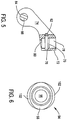
- FIGS 1 and 2 illustrate a type of a surgical sagittal saw, an acetabular cup remover 40, of this invention and the relation of the tool to an acetabular cup 42.
- the cup 42 is often in the form of a hollow semi-spherical structure typically formed of metal.
- the outer surface of the cup 42 is embedded in the bone of the hip.
- the inner surface of the cup 42 defines a socket (not illustrated). This socket is designed to receive the ball of a femoral stem.
- a liner often in the form of a hollow semi-spherical structure, may be seated against the inner surface of the cup 42. The liner, when present, defines the socket space that receives the femoral ball.
- the cup remover 40 includes a pivot head 66.
- Pivot head 66 is the portion of the cup remover 40 that is seated in the cup 42.
- a coupler 58 extends proximally away from the head.
- the coupler 58 is an elongated structure.
- Proximally it is understood means towards the surgeon using the cup remover 40, away from the cup 42.
- distal means away from the surgeon, towards the cup 42.
- a shaft 54 extends proximally from the distal end of the coupler 58.
- a saw head 70 is connected to the coupler so as to be located less than 4 cm proximally away to where the coupler extends away from the cup.
- the saw head 70 is pivotally connected to the coupler 58.
- saw head 70 of an acetabular cup remover is sometimes referred to as a hinge.
- a blade 130 is removably attached to and extends outwardly from the saw head. Blade 130 is shaped so, when the saw head 70 is pivoted in the forward direction, the blade extends around the outer surface of the cup 42.
- a handle 56 is slidably connected to the shaft 54 at a location slightly forward of the proximal end of the shaft.
- An actuator rod 59 is located adjacent to and extends distally forward with the shaft 54.
- the proximal end of the actuator rod 58 is connected to the handle 56 so that the rod moves with the handle.
- An actuator 60 is connected to the distal end of the actuator rod.
- Actuator 60 is formed to have an elongated slot 61.
- the actuator 60 is shaped so that as slot 61 extends proximally, the slot extends outwardly from the longitudinal axis of the actuator 60.
- a pin 62 that extends through slot 61 connects the actuator 60 to the saw head 70.
- the longitudinal movement of the handle 56 over the shaft 54 results in the like longitudinal movement of the actuator rod 59 and actuator 60 relative to the shaft 54.
- the longitudinal movement of the actuator 60 causes the saw head 70 to pivot. This pivoting is around an axis that is perpendicular to the longitudinal axis of the actuator rod 59.
- the pivoting of the saw head 70 results in the blade 130 being pivoted either distally forward, against the bone surrounding the acetabular cup 42 or proximally, away from this tissue.
- the proximal end of the shaft 54 is attached to a driver 50.
- the driver 50 is a surgical handpiece. Internal to the driver is a motor 51, represented as a phantom cylinder.
- the driver rotates the shaft 54 and by extension, the components attached to the shaft. These components include the blade 130.
- the driver 50 is configured so that when the driver is actuated, the driver oscillates the shaft 54 back and forth around the longitudinal axis of the shaft.
- the shaft 54 is oscillated while the saw head 70 is in the forward position, the movement of the shaft results in the blade 130 being driven back and forth against the bone against which the blade is pressed.
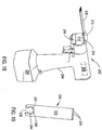
- the saw head 70 as seen in Figures 3-5 is a single piece component.
- Saw head 70 includes a base 72 that is generally rectangular in shape.
- Two parallel legs 74 one identified in Figures 4 and 5 , project outwardly from one end of the base.
- the head 70 is dimensioned so that legs 74 slip fit over opposed sides of the coupler 58.
- Each leg 74 is formed to have a rounded free end (not identified).
- Saw head 70 is further formed to have a rectangular slot 76 that extends through the base 72.
- a circular bore 78 extends downwardly from the top of the base 72. Bore 78 intersects and extends below slot 76.
- the saw head 70 is further formed so, above slot 76, bore 78 has a small ledge 79. Bore 78 opens into a bore 80. Bore 80 is coaxial with and has a smaller diameter than bore 78.
- the saw head 70 is formed so that each leg 74 is formed with two bores that extend side-to-side through the leg. Each leg 74 has a bore 82 located adjacent where the leg extends outwardly from the base 72. Bores 82 are coaxial. The saw head 70 is further formed so that bores 82 partially intersect the rear end of slot 76. Each leg 74 is further formed with a bore 84. Bores 84 are formed in the free ends of the legs 74 and are coaxial.
- a pin 88 extends through the coupler and the leg bores 84. Pin 88 pivotally holds the head 70 to the coupler 58.
- Pin 62 extends through actuator slot 61 into saw head bores 82.
- Pin 62 extends outwardly from the leg 74 adjacent the actuator.
- the pin 90 is able to slide within slot 61.
- the saw is designed so that that the proximal to distal movement of the actuating rod 59 and actuator 60 cause the actuator to pivot the saw head 70 about pin 88. Given that pin 62 extends between the saw head legs 74, it should be understood that the pin 62 extends across the open rear end of head slot 76.
- a pin 94 is moveably mounted to the saw head base 72.
- Pin 94 as seen in Figures 6 , 7 and 8 , is a single piece component that has a cylindrical head 96. (In the Figures the head is seen as the bottommost component of the pin because the head 96 is the distalmost component of pin 94.)
- Pin head 96 is dimensioned to slip fit in the saw head bore 80.
- a neck 98 is located immediately above the head. Neck 98, in planes perpendicular to the longitudinal axis of the pin 94, has a cross sectional shape that is non-circular. In the illustrated version of the invention, neck 98 has a cross sectional shape that is elliptical.
- the major and minor axes of the neck are both longer in length than the diameter of the saw head bore 80 and pin head 96.
- the pin Above the top of the neck 98 the pin has a waist 104.
- Waist 104 is circular in cross section. More particularly, pin 94 is formed so that the diameter of the waist 104 is equal to the length of the major axis of the neck 98.
- Each shoulder 102 extends outwardly from the top of the neck 98.
- Each shoulder 102 is symmetrically centered over one end of a line that is an extension of the minor axis of the neck 98.
- Each shoulder extends outwardly from the neck to the waist 104.
- the radial length of the shoulder increases moving distally to proximally along the pin 94.
- Each shoulder 102 thus has an outer surface that is chamfered, is tapered.
- Pin 94 is further formed to have a stem 106 that extends upwardly from waist 104.
- Stem 106 has a shape that in cross section can be considered to be of a flattened oval.
- the curved end faces of stem 106 are not completely semi-circular in shape.
- a coil spring 112 is disposed around the pin stem 106.
- a cap 114 is seated in bore 78.
- Cap 114 seats on ledge 79.
- the cap 114 is formed with an opening 116, identified in Figure 4 , dimensioned to receive the pin stem 106.
- Cap opening 116 has a cross sectional shape similar to but larger in size than the cross sectional shape of the pin stem.
- the components forming the saw are dimensioned so that the stem can freely move in the cap bore 116. Not identified is a void internal to the cap dimensioned to receive the spring 112.
- the components of the saw are dimensioned so that the spring 112 is compressed between the underside of the cap 114 and the circular stepped surface of the waist 104 that protrudes radially outwardly from the pin stem 106.
- Spring 112 thus normally urges the pin downwardly.
- the spring 112 is selected so the force the spring places on pin 94 can be overcome by finger force.
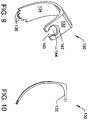
- the blade 130 of this invention is now described by reference to Figures 9-12 .
- the blade 130 is a single piece unit and is typically formed from material that can be sharpened and sterilized. Often the blade 130 is formed from stainless steel.
- Blade 130 is formed to have a rectangularly shaped foot 132. Foot 132 is the most proximal portion of the blade 130. The foot 132 is dimensioned to closely slip fit in the slot 76 internal to the saw head 70.
- a trunk 134 extends distally forward from foot 294. In the versions of the invention in which the saw functions as an acetabular cop remover, the trunk is dimensioned to extend around the outer surface of the acetabular cup 42 the blade 130 is intended to remove. Thus the trunk 134 is curved both along its longitudinal axis and lateral axis. Teeth 136 protrude outwardly from the distal end of the trunk 134. The teeth 136 are the most distal features of the blade 130.
- Blade 130 is further formed so that a slot 140 extends distally forward from the proximal end of the blade foot 132.
- Slot 140 has a width slightly greater than the diameter of the pin head 96 and less than the length of the minor axis of the neck 98.
- the blade 130 is formed so that slot 140 opens up into two contiguous voids in the blade foot 132 both of which are located distal to the proximal end of the blade. A first one of these voids is opening 142. Opening 142 extends downwardly from the top planar face of the foot 132. Opening 142 is circular in shape. Opening 142 is further formed to be tapered or beveled. More particularly, as the distance from the top planar surface of the foot 132 increases, the diameter of opening 142 decreases.
- Opening 142 thus is defined by tapered surface 141 of the blade 130.
- the blade 130 is shaped so that pin shoulders 102 can seat in opening 142.
- Opening 142 opens into a through bore 144, the second of the two contiguous voids.
- Through bore 144 extends from the opening 142 to the bottom face of the blade foot 132.
- the blade 130 is shaped so that the dimensions of the through bore are constant along the length of the bore.
- the blade is further shaped so that pin neck 98 can closely seat in the through bore 144.
- the through bore 144 is elliptical in shape.
- the major axis of the through bore is perpendicular to the proximal to distal longitudinal axis along the blade.
- the major axis of the through bore has a length that is approximately 0.2 mm greater than the major axis of the pin neck 98.
- the blade 130 is further shaped so that the opening 142 is not centered on the major axis of the through bore 144.
- dashed line 146 represents a diameter across the opening 142 perpendicular to the longitudinal axis of the blade.
- Dotted line 148 represents the major axis of the through bore 144.
- the center of opening 142 is located distally forward of the major axis of the through bore 148.
- opening 142 is circular in shape. Accordingly, in this version of the invention, the blade is constructed so that major axis 148 of through bore 144 is offset from the center of the opening 142.
- Part of the process of preparing the acetabular cup remover 40 of this invention for use is the fitting of the blade 130 to head 70.
- pin head 96 is pushed upwardly.
- the finger force placed on the pin overcomes the force spring 112 imposes on the pin 94.
- Pin 94 moves along a path of travel coincident with the longitudinal axis of the pin.
- the pin head 96 moving upwardly, the pin is translated so that the section of the pin head adjacent neck 98 moves into head slot 76.
- the pin is in the load position.
- Blade 130 is inserted in the slot 76. More particularly, the blade 130 is generally inserted in the slot 76 so that the blade through opening 144 is approximately in registration with the pin neck 98.
- the finger force used to hold the pin 94 in the load positon is then released. This results in the release of the potential energy stored in the spring 112.
- the spring 112 acts against the pin 94 to return the pin to the run or locked position.
- the pin neck extends through blade opening 142 into the through bore 144.
- one of the pin shoulders 102 strikes blade tapered surface 141. More particularly, owing to the opening 142 and through bore 144 not being concentric, the proximally directed pin shoulder 102 strikes the proximal sections of blade tapered surface 141. This event occurs before the distally directed shoulder 102 strikes the distal section of surface 141.
- pin 94 urges the blade proximally rearward. More particularly, the blade is urged rearward until the proximally directed end of blade 130 abuts pin 62 integral with saw head 70. Pin 62 thus acts as a stop that prevents further movement of the blade in head slot 76. Saw 40 including blade 130 of this invention is then ready for use.
- Saw 40 is used by actuating the motor 51. This results in the driver 50 oscillating the shaft 54.
- the pivoting of the shaft 54 results in a like pivoting of saw head 70 and, by extension blade 130.
- Handle 56 is urged downwardly to cause the blade to extend around the acetabular cup 42.
- the blade teeth 136 excise the tissue surrounding the cup. The excising of this tissue makes it possible to extract the implanted acetabular cup 42.
- the saw 40 and blade 130 of this invention is designed so that, owing to the arrangement of the components, the pin 94 holds the blade 130 against pin 62 integral with the saw head.
- the blade 130 can be considered to be clamped between pin 62 and pin 94.
- the blade is clamped along the proximal-to-distal longitudinal axis of blade foot 132.
- Pivot head 66 while able to rotate relative to the acetabular cup 42 has a fixed center relative to the cup 42. This means the saw head rotates around an arc that is fixed relative to the cup 42. Since blade 130 is forced against pin 62, the blade is in a fixed position relative to the saw head 70.
- Blade 130 therefore likewise moves around an arc that is fixed relative to acetabular cup 42. This means that the blade 130 can be shaped to move along paths of travel that, while relative close to the surface of the cup 42, do not intersect the cup.
- the saw of this invention is designed to minimize the removal of tissue around the acetabular cup the saw is employed to remove. The minimization of this tissue removal reduces the extent to which the remaining tissue needs to heal after the procedure in which the acetabular cup remover of this invention is employed.
- the pivotal motion of the pin 94 is transferred to the blade along the non-circular interface between pin neck 98 and the adjacent non-circular surface of the saw that defines through opening 144. This reduces the extent to which the oscillatory motion of the blade 130 lags the oscillatory motion of the saw head 70. The reduction in the extent to which these two motions varies reduces the problems that occur when these motions are not substantially identical.
- a further feature of the saw and blade of this invention is associated with the movement of the pin between the run/locked and load positions. As discussed there is some clearance between the pin stem 106 and the surrounding cap 114. This clearance facilitates the ability to use finger force to displace the pin from the run/locked state to the load position. A consequence of the presence of this clearance is that pin 94 is able to engage in a limited degree of rotation relative to the saw head 70. As a result of this rotation of pin 94, there may be instances in which the major axis pin neck 96 is not in alignment with the major axis of blade through opening 144. When this event occurs, and the finger force on the pin is released, the spring 112 moves the pin 94 towards the run/locked position.
- pin 94 The downward movement of the pin 94 results in the edge around the perimeter of the pin neck 98 striking the blade tapered surface 141. As a consequence of surface 141 being tapered, the downward force is converted into a force that rotates the pin 94. The more particularly, pin 94 is rotated to cause the neck to move back to the orientation in which the major axis of the neck is in alignment with the major axis of blade through opening 150. This ensures that pin 94 fully seats in the blade 130.
- FIGs 13 and 14 illustrate an alternative saw head assembly and blade 130a constructed in accordance with this invention.
- the saw head assembly includes the previously described saw head 70.
- a pin 160 is slidably disposed in the saw head 70.
- the pin 160 as seen in Figure 15 includes a circularly shaped head 162.
- Above the head 162, pin 160 is formed with a neck 168.
- Neck 168 is similar to previously described pin neck 98 in that both necks are elliptical in cross sectional shape. Specifically, the major axis of neck 168 is equal to the diameter of the pin head.
- the minor axis of the neck 168 is less than the diameter of the pin head.
- Pin 160 is further shaped so that head 162 while being generally circular in shape, is formed with two symmetrically opposed strike surfaces 164. Each strike surface 164 tapers such that extending upwardly from the pin head 162 the surface extends diagonally toward an adjacent terminus of the minor axis of the neck 168.
- Pin 160 is further formed to have a shaft 170 that extends upwardly from the neck 168.
- Shaft 170 is cylindrical in shape and has a diameter less than the length of the minor axis of the neck 168.
- a stop ring 172, also part of the pin 160 extends radially outwardly from the shaft 170. Pin 160 is shaped so the stop ring is spaced away neck 168. Stop ring 172 is circular in shape and has a diameter greater than that of shaft 170.
- a stem 174 extends upwardly from the stop ring 172 so as to be the topmost portion of pin 160. Stem 172 is similar in shape to the previously described pin stem 106.
- Pin 160 is moveably mounted in saw head base 72 as seen in Figure 14 .
- a cup 176 is seated in base bore 78. Not identified is the hole in the base of the cup 176 through which the pin 160 extends into and through slot 76. Cup 176 projects above the saw head base.
- a cap 178 extends around the section of the base that extends above the base. The top of the cap 178 is formed with an opening 180 similar to opening 116 is cap 114.
- pin head 162 and neck 168 are generally disposed in slot 76 internal to saw head 70.
- Pin shaft 170 and stop ring 172 are disposed in cup 176 and cap 178.
- a coil spring 180 is disposed around the pin shaft 170.
- Spring 180 extends between either the surface internal to the head 70 that defines the base of bore 78 or the base of the cup 176 to stop ring 172.
- Spring 180 presses against the stop ring 172 to hold the stop ring away from head slot 76.
- the abutment of the stop ring against the undersurface of the top of cap 178 limits the upward movement of the pin 160.
- Blade 130a is similar to blade 130.
- Blade 130a includes a foot 132a.
- Previously described trunk 134 extends downwardly from foot 134. While not seen in the Figures depicting blade 130a it us understood that previously described teeth 136 extend forward from trunk 134.
- Blade 130a is formed so as to have a slot 181 extend forward from the proximal end of foot 132a.
- Slot 181 has a width slightly greater than the diameter of pin shaft 170.
- Slot 181 opens up into two contiguous void spaces. One of these void spaces is opening 184.
- Opening 184 extends upwardly from the underside of foot 132a.
- Opening 184 is in cross section circular in shape.
- the diameter of opening 184 like the diameter of opening 142, varies along the length of the opening. Specifically, extending upwardly from the underside face of foot 132a, the diameter of opening 184 decreases. Opening 184 is thus defined by blade tapered surface 182.
- Blade 130a is shaped so the section of the pin head 162 that defines surfaces 164 can seat in opening 184.
- Opening 184 opens into the second void space, through bore 186.
- Through bore 186 extends upwardly from opening 184 to the top face of the blade foot 132a.
- the blade 130a is
- Blade 130a is further formed so that opening 184 and bore 186 are not concentric.
- the center of opening 184 is located forward of the major axis through the bore 186.
- Figure 18 illustrates that this invention may be incorporated into what can be considered a conventional sagittal saw 202.
- a convention sagittal saw is understood to be a saw used to oscillate the planar blade 220 of Figure 19 around an axis that extends through the plane of the blade, an axis extending in and out of the plane of Figure 19 .
- Saw 202 includes a pistol shaped body 204.
- a motor 206 represented as a dashed cylinder is disposed inside the barrel of the body.
- a battery 208 is shown attached to the butt end of the handgrip integral with the body 204. Battery 208 provides the charge used to energize the motor 206.
- a static head 210 extends forward from the distal end of the barrel of the body 204.
- a blade mount 212 is rotatably mounted to head 210.
- Blade mount 212 is analogues in function to the previously described saw head 72.
- the blade mount 212 is thus the component of saw 202 to which the blade 230 is releasably mounted.
- the blade mount 212 includes an elongated rod like stem, not illustrated.
- the stem is rotatably mounted to the static head 210.
- the stem extends to a head portion of the blade mount. This blade mount head is the portion of the blade mount 212 disposed above the static head 210 in Figure 18 .
- a transmission assembly extends between the motor 206 and the stem of the blade mount 212. This transmission converts the rotational motion of the shaft of motor 206 into a motion that oscillates the blade mount stem and by extension the whole of the blade mount 212 and the blade 230 mounted to the blade mount.
- the head of the blade mount 212 is formed with a slot 214 for receiving the proximal end of the blade 230. While not seen, it is understood that disposed in the blade mount is a pin. This pin is similar to previously described pin 160. This pin is mounted to the blade mount such that relative to gravity, the pin head is the top most component of the pin. In some versions of the invention, this pin is slidably mounted in the stem of the blade mount 212. A clamping assembly, represented by finger lever 216, raises and lowers the pin. When the pin is lowered, the pin head presses against the blade 230. When the pin is in this state, the pin is in the run/locked state. The clamping assembly is able to raise the pin.
- the blade 230 designed for use with saw 202 as seen in Figure 19 includes a planar body 232. Teeth 234 extend forward from the distal end of the body. Blade 230 is formed to have a slot 238 that extends forward from the proximal end of the body. Slot 238 extends to an opening 242 and a bore 244 that collectively form a top-to-bottom through hole in the blade body 232. Opening 242 is similar in shape to opening 144. Opening 242 is defined by tapered surface 240. Opening 242 extends from the face of the blade body in which the opening is formed into through bore 244. Through bore 244 is similar in shape to through bore 144. The center of opening 242 is located forward of the major axis through the through bore 244.
- Blade 230 is mounted to saw 202 by setting the clamp assembly so the pin internal to the blade mount 212 is displaced. More particularly, the pin is displaced so the pin head and neck are moved upwardly, away from the surface internal to the head of the blade mount 212 that defines the base of slot 214. The blade 230 is seated in the slot so that the blade opening 242 and through opening 244 are located below the neck and head of the pin. The clamp assembly is then actuated to move the pin from the load position to the run/locked position. More specifically, the clamp assembly is actuated to lower the pin neck and head toward the base of the slot 214. As a result of this displacement of the pin, the pin neck seats in the blade through opening 244.
- the pin head surfaces analogues to strike surfaces 164 are pressed against the blade tapered surface 240.
- this axis is typically the proximal-to-distal longitudinal axis along the length of the blade.
- the blade is so displaced until the blade is pushed against a static surface integral with the blade mount. The blade is thus clamped along two axes. First, as result of the head of the pin head pressing against the face of the blade, the blade is clamped along the top-to-bottom axis between the opposed faces of the blade.
- the opposed surface against which the blade is clamped is the surface on which the blade is seated.
- the blade is clamped between the pin and the blade mount static surface, this clamping is along the proximal-to-distal longitudinal axis along the blade 230.
- the non-circular geometry of the pin neck and complementary blade through bore 244 inhibit rotation of the blade. The pin thus holds blade 230 fast to the blade mount 212 so the blade mount and blade move as a single unit.
- an alternative conventional sagittal saw of this invention may be constructed so that pin that to translate the pin that releasably holds the blade to the blade mount is downwardly displaced in order to move the pin from the run/locked position to the load position.
- the motor is an electrically driven motor and the motor is powered by a battery that is not a requirement of all versions of the invention.
- the motor may be a pneumatic or hydraulic motor.
- the saw may be attached to a console that provides the power for actuating the motor.
- the geometric features of the components of this invention may vary from what has described.
- the blade through bore and complementary section of the pin that seats in this opening be elliptical in shape. At a minimum this bore is typically non-circular.
- the through bore may be defined by an interior surface of the blade that is either curved or straight.
- the through bore may different by surfaces that meet at defined, non-circular corners, vertices.
- the through bore be oval or a polygonal in shape.
- the through bore may be defined by a combination of interior surfaces of the blade that are both straight and curved.
- the through bore is formed to have a major axis that is greater in length than one or more minor axes that further define the shape of the bore.
- the ratio of the length of the major axis of this bore to the minor axis is 1.2 to 1 or more.
- the ratio of the length of the major axis of this bore to the minor axis is 1.35 to 1 or more.
- the through bore be formed so that the major axis is perpendicular to the proximal-to-distal longitudinal axis along the blade.
- the major axis of the through bore may be offset from the blade longitudinal axis.
- the blade may be shaped so the major axis of the through bore is aligned with or parallel to the longitudinal axis along the body of the blade.
- this invention is not limited to constructions where the opening into the through bore is circular in shape.
- this opening may have other shapes. These shapes may even include shapes with one or more straight surfaces. In versions of the invention wherein this opening has straight surfaces, two of these adjacent surfaces may meet at a corner.
- this opening into the through bore may be symmetric about an axis that extends across this opening.
- the opening may be defined by one or more tapered surfaces that do not extend completely circumferentially around the through bore. Here the interruption due to slot 140 is ignored.
- the tapered surface may only subtend an arc around the center of the opening that is greater than 180°.
- the tapered surface may subtend an arc of 180° or less.
- this opening could be defined by a tapered surface adjacent one section of the through bore and adjacent this tapered surface a surface that is extension of the inner surface of the blade that defines the through bore.
- the blade be formed so that the opening and adjacent through bore are centered on axis that are offset from each other.
- these two void spaces are located on axis that are offset
- the voids are arranged so that the axis through the opening is located distally forward of the axis through the through opening.
- the above arrangement is preferred if there is a reason to, upon securing the blade to the saw, urge the blade proximally.
- the blade can be designed so that the axis through the opening would be laterally spaced from the axis through the blade through bore. In still other constructions of the invention, it is useful to, upon securing the blade to the saw head, urge the blade distally forward. In these constructions of the invention, the blade can be shaped so that so that the axis through the opening is located proximal to the axis through the blade through bore.
- the static surface integral with the saw head against which the blade is pushed may not be the surface of a separate component, pin 62 in the primary described versions of the invention.
- This static surface may simply be an inner surface of the saw head that defines the perimeter of the blade slot.
- the static surface may be the surface of a tab integral with the saw head that protruded into the slot.
- the blade it may not be necessary to form the blade so that that the opening and adjacent through bore are centered on axes that offset from each other.
- the goal of providing a blade that, when exposed to the unidirectional motion of the pin along one axis is displaced along a second axis that is angularly offset from the axis along which the pin moves can be accomplished by shaping the blade so that the taper, the chamfer, around the opening has an angle that varies around the circumference of the opening.
- it is desirable to displace the blade proximally, towards pin 62 in Figure 5 one could provide a blade wherein the taper of the proximal section of the opening is shallower than the taper around the distal section of the opening.
- the proximally directed shoulder When the pin moves against the surfaces of the blade that define the opening, the proximally directed shoulder would strike the shallow adjacent tapered surface of the blade before the distally directed shoulder strikes the opposed opening-defining surface with the more pronounced taper. This would result in the proximally directed pin shoulder urging the blade proximally, against pin 62.
- the opening into the through bore may not even be tapered around the whole of the circumference of the opening.
- the assembly can still be designed so that when the pin moves to the run/locked position the blade is displaced along a desired axis. In these versions of the invention this movement is accomplished by shaping the pin so that shoulder surfaces are asymmetric relative to each other.
- the pin is constructed so, relative to the longitudinal axis of the pin, the proximally directed pin extends radially outwardly than the opposed distally directed pin.
- the proximally directed shoulder will strike the adjacent tapered surface before the opposed shoulder strikes the distally directed surface. This action would result in the desired movement of the blade along an axis that is angularly offset from the axis along with the saw head pin travels.
- the pin may therefore only have a single shoulder with a blade-striking surface that is tapered or chamfered outwardly.
- the saw head components and blade are designed so that when the saw head pin moves against the blade, the blade moves along an axis that is perpendicular to the axis of travel of the pin. While these movements are along axes that are angularly offset, there is no requirement that in all versions of the invention, these two axes be perpendicular.
- coil springs may be used to bias the pin in the run/locked position against the blade.
- the saws of this invention may have shapes and features different from what has been described.
- an acetabular cup remover of this invention may not have a pivot head. Instead the most distal portion of this saw may be a plug or boss. The plug/boss rotates in a bore associated with the cup 42 being removed.
- the acetabular cup remover and by extension the attached saw blade only rotates around the cup 42. The saw and blade do not pivot together around the cup.
- a standard sagittal saw of this invention may have a pencil shaped body. This type of saw is held in the web between the thumb and forefinger of the hand of the surgeon. This type of saw is typically used for small bone surgery, surgeon on the hand or foot bones.
- the blade is typically designed for use with a sagittal surgical saw
- the features of this invention may be incorporated into other assemblies.
- These assemblies include saws designed to reciprocate the attached blades.
- reciprocation is understood to be back and forth movement on a path of travel that is in line with the longitudinal axis along the blade.
- the invention may be incorporated into saws and other devices not used for medical purposes.
Landscapes
- Health & Medical Sciences (AREA)
- Engineering & Computer Science (AREA)
- Life Sciences & Earth Sciences (AREA)
- Surgery (AREA)
- General Health & Medical Sciences (AREA)
- Orthopedic Medicine & Surgery (AREA)
- Oral & Maxillofacial Surgery (AREA)
- Biomedical Technology (AREA)
- Heart & Thoracic Surgery (AREA)
- Veterinary Medicine (AREA)
- Public Health (AREA)
- Animal Behavior & Ethology (AREA)
- Mechanical Engineering (AREA)
- Molecular Biology (AREA)
- Medical Informatics (AREA)
- Nuclear Medicine, Radiotherapy & Molecular Imaging (AREA)
- Dentistry (AREA)
- Transplantation (AREA)
- Physical Education & Sports Medicine (AREA)
- Cardiology (AREA)
- Vascular Medicine (AREA)
- Surgical Instruments (AREA)
- Prostheses (AREA)
Claims (21)
- Lame (130, 130a, 230) pour une utilisation avec une scie chirurgicale sagittale (50, 202), ladite lame comprenant :un corps (132, 132a, 134, 232) avec des extrémités proximale et distale opposées et des faces opposées ;des dents (136, 234) pour couper du tissu, les dents s'étendant vers l'avant depuis l'extrémité distale du corps ; etun espace vide (144, 186, 244) formé dans le corps adjacent à l'extrémité proximale du corps qui s'étend entre les faces opposées,caractérisée en ce quel'espace vide est défini par :une ouverture (142, 184, 242) qui s'étend vers l'intérieur à partir d'une première face des faces du corps de lame, l'ouverture étant au moins partiellement définie par une surface (141, 182, 240) qui se rétrécit vers l'intérieur à partir de la première face du corps de lame de manière à avoir un diamètre maximum adjacent à la première face du corps de lame ; etun alésage traversant (144, 186, 244) qui s'étend de l'extrémité de l'ouverture (142, 184, 242) espacée de la première face à la seconde face du corps de lame, le corps de lame étant formé de sorte que l'alésage traversant présente une forme qui n'est pas circulaire et qui est en outre formée pour définir un axe principal (148) à travers l'alésage traversant et au moins un axe mineur à travers l'alésage traversant, l'axe principal étant plus long en terme de longueur que l'au moins un axe mineur et plus court en terme de longueur qu'une distance maximale à travers la partie de l'ouverture adjacente à la première face.
- Lame selon la revendication 1, dans laquelle le corps de lame est en outre formé de telle sorte que :l'ouverture (142, 184, 242) est symétrique autour d'un axe (146) à travers l'ouverture ; etl'alésage traversant est formé de telle sorte que l'axe principal (148) à travers l'alésage traversant ne soit pas aligné avec l'axe (146) à travers l'ouverture (144, 184, 242).
- Lame selon la revendication 2, dans laquelle le corps de lame est en outre formé de telle sorte que l'axe principal (148) à travers l'alésage traversant soit au moins partiellement situé à proximité de l'axe (146) à travers l'ouverture (144, 184, 242).
- Lame selon l'une quelconque des revendications 1 à 3, dans laquelle le corps de lame (132, 132a, 134, 232) est en outre formé de telle sorte que :un axe longitudinal s'étend entre les extrémités proximale et distale opposées ;un axe (146) s'étend à travers l'ouverture (142, 184, 242) ; etau moins l'un de l'axe (146) à travers l'ouverture et l'axe principal (148) à travers l'alésage traversant est perpendiculaire à l'axe longitudinal du corps de lame.
- Lame selon la revendication 4, dans laquelle à la fois l'axe (146) à travers l'ouverture (144, 184, 242) et l'axe principal (148) à travers l'alésage traversant sont perpendiculaires à l'axe longitudinal du corps de lame.
- Lame selon l'une quelconque des revendications 1 à 5, dans laquelle l'ouverture (144, 184, 242) est de forme circulaire.
- Lame selon l'une quelconque des revendications 1 à 6, dans laquelle l'alésage traversant (44, 186, 242) est de forme elliptique.
- Lame selon l'une quelconque des revendications 1 à 7, dans laquelle le corps de lame (132, 132a, 134, 232) est en outre formé avec une fente (140, 181, 238) qui s'étend depuis un périmètre extérieur du corps de lame (132, 132a, 134, 232) jusqu'à l'ouverture (142, 184, 242) et l'alésage traversant (144, 186, 244), la fente ayant une longueur transversale qui est inférieure à la longueur de l'axe principal (148) à travers l'alésage traversant.
- Lame selon l'une quelconque des revendications 1 à 8, dans laquelle le corps de lame (232) est de forme plane.
- Lame selon l'une quelconque des revendications 1 à 8, dans laquelle le corps de lame (130, 130a) est formé de manière à avoir entre l'extrémité proximale et les dents (136) un tronc (134) qui s'incurve à l'opposé de l'extrémité proximale.
- Lame selon l'une quelconque des revendications 1 à 10, dans laquelle le corps de lame est en outre formé de telle sorte que la surface effilée (141, 240) qui définit au moins partiellement l'ouverture (142, 186, 244) sous-tend un arc supérieur à 180° autour de l'ouverture.
- Scie chirurgicale sagittale (50, 202) comprenant la lame selon l'une quelconque des revendications 1 à 11.
- Scie chirurgicale sagittale selon la revendication 12, dans laquelle la scie (50) est adaptée pour retirer une cupule acétabulaire (42).
- Ensemble scie chirurgicale comprenant :une lame (130, 130a, 230) ayant : des extrémités proximale et distale opposées ; et des faces opposées ; un espace vide (144, 186, 244) en avant de l'extrémité proximale entre les faces opposées ; et des dents (136, 234) qui s'étendent vers l'avant depuis l'extrémité distale ; etune scie (50, 202) avec : une tête pivotante (70, 212) qui est formée afin de définir une fente (76, 214) façonnée pour recevoir l'extrémité proximale de la lame et une surface statique (62) adjacente à la fente de la tête ; et une broche (94, 160) disposée dans la tête qui s'étend au moins partiellement à travers la fente, la broche pouvant se déplacer le long d'un axe et étant dimensionnée pour s'asseoir dans l'espace vide de lame afin de maintenir de manière amovible la lame sur la tête,caractérisé en ce que :la broche (94, 160) a un col (98, 168) et l'espace vide de la lame est défini en partie par un alésage traversant (144, 186, 244) dimensionné pour recevoir le col, le col de la broche et l'alésage traversant de la lame ayant des formes non circulaires complémentaires de sorte que le col de la broche puisse s'asseoir dans l'alésage traversant de la lame et de telle sorte que le col de la broche et l'alésage traversant de la lame aient chacun un axe principal et au moins un axe mineur, chaque axe principal étant plus long en terme de longueur que l'au moins un axe mineur ; etla broche (94, 160) est formée avec au moins un épaulement (102, 164) adjacent au col (98, 168) qui s'étend vers l'extérieur à partir du col et l'espace vide de la lame est en outre défini par une ouverture (142, 184, 242) dans l'alésage traversant à partir de l'une des faces de la lame, l'ouverture de la lame étant effilée et dimensionnée pour recevoir le col de la broche et l'épaulement de la broche, l'au moins un épaulement de la broche et l'ouverture de la lame étant formés collectivement de sorte que le mouvement du col de la broche dans l'alésage traversant de la lame fait que l'épaulement de la broche heurte une surface effilée (141, 182, 240) de la lame qui définit l'ouverture de la lame de sorte que la lame se déplace le long d'un axe décalé angulairement de l'axe le long duquel la broche se déplace dans la tête de la scie (70, 212) de sorte que la lame soit poussée contre la surface statique (62) adjacente à la fente de la tête (76, 214).
- Ensemble scie chirurgicale selon la revendication 14, dans lequel :la tête pivotante (70, 212) est en outre formée de sorte que la fente (76, 214) s'étend de manière proximale vers l'intérieur depuis une extrémité distale de la tête et la surface statique (62) à une extrémité proximale de la fente ; etladite broche (94, 160) et la lame (130, 130a, 230) sont formées collectivement de telle sorte que, lorsque l'épaulement (102, 164) de la broche heurte la surface effilée (141, 182, 240) qui définit l'ouverture de la lame (142, 184, 242), la lame est déplacée de manière proximale de sorte que l'extrémité proximale de la lame soit poussée contre la surface statique (62) adjacente à la fente de la tête (76, 214).
- Ensemble scie chirurgicale selon les revendications 14 ou 15, dans lequel :
la broche (94) est en outre formée pour avoir une tête (96), ladite tête de broche (96) formant une extrémité de la broche (94), dans lequel ledit col (98) est situé adjacent à ladite tête (96) et ledit au moins un épaulement (102) est formé de telle sorte que, lorsque ledit épaulement (102) s'étend vers l'extérieur à partir dudit col (98), ledit épaulement se rétrécit en s'éloignant de ladite tête de broche (96). - Ensemble scie chirurgicale selon les revendications 14 ou 15, dans lequel la broche (160) est en outre formée pour avoir une tête (162), ladite tête de broche (162) formant une extrémité de ladite broche (160), dans lequel ledit col (168) est adjacent à ladite tête (162) et ledit au moins un épaulement (164) est en outre formé de telle sorte que, lorsque ledit épaulement (164) s'étend vers l'extérieur à partir dudit col (168), ledit épaulement (164) se rétrécit vers ladite tête de broche (162).
- Ensemble scie chirurgicale selon l'une quelconque des revendications 14 à 17, dans lequel : la broche (94, 160) est formée avec plusieurs épaulements (102, 164) qui se rétrécissent en s'éloignant du col (98, 168).
- Ensemble scie chirurgicale selon l'une quelconque des revendications 14 à 18, dans lequel la broche (94, 160) est formée de telle sorte que le col soit de forme elliptique.
- Ensemble scie chirurgicale selon l'une quelconque des revendications 14 à 19, dans lequel la lame (130, 130a) et la scie (50) sont collectivement adaptées de sorte que la scie peut être reçue dans une cupule acétabulaire (42) et que la lame peut être retirée de la cupule acétabulaire.
- Ensemble scie chirurgicale selon l'une quelconque des revendications 14 à 19, dans lequel la lame (230) se trouve dans un plan et la scie (202) est conçue pour faire osciller la lame autour d'un axe qui s'étend à travers le plan de la lame.
Applications Claiming Priority (1)
| Application Number | Priority Date | Filing Date | Title |
|---|---|---|---|
| US201562105795P | 2015-01-21 | 2015-01-21 |
Publications (2)
| Publication Number | Publication Date |
|---|---|
| EP3050521A1 EP3050521A1 (fr) | 2016-08-03 |
| EP3050521B1 true EP3050521B1 (fr) | 2020-12-23 |
Family
ID=55221257
Family Applications (1)
| Application Number | Title | Priority Date | Filing Date |
|---|---|---|---|
| EP16000121.0A Not-in-force EP3050521B1 (fr) | 2015-01-21 | 2016-01-20 | Scie sagittale chirurgicale et lame complémentaire avec des caractéristiques qui retiennent solidement la lame statique sur la scie |
Country Status (2)
| Country | Link |
|---|---|
| US (1) | US10342553B2 (fr) |
| EP (1) | EP3050521B1 (fr) |
Families Citing this family (11)
| Publication number | Priority date | Publication date | Assignee | Title |
|---|---|---|---|---|
| GB201319811D0 (en) * | 2013-11-11 | 2013-12-25 | Academisch Ziekenhuis Leiden | A tool assembly and associated apparatus |
| US10342553B2 (en) | 2015-01-21 | 2019-07-09 | Stryker European Holdings I, Llc | Surgical sagittal saw and complementary blade with features that fixedly hold the blade static to the saw |
| USD816219S1 (en) * | 2016-08-25 | 2018-04-24 | Shukia Medical | Slap hammer |
| US11612501B2 (en) | 2018-10-19 | 2023-03-28 | Tightline Development, LLC. | Hip and knee joint stem explant system and methods of using the same |
| DE102018130381A1 (de) * | 2018-11-29 | 2020-06-04 | Aesculap Ag | Chirurgisches Werkzeug mit Effektoraufnahme |
| US11490898B2 (en) | 2019-10-18 | 2022-11-08 | Depuy Synthes Products, Inc | Surgical saw blade |
| US11771475B2 (en) | 2020-10-07 | 2023-10-03 | Globus Medical, Inc. | Systems and methods for surgical procedures using band clamp implants and tensioning instruments |
| US11974785B2 (en) | 2020-10-16 | 2024-05-07 | Globus Medical, Inc | Band clamp implants |
| US12029661B2 (en) * | 2022-01-19 | 2024-07-09 | Adam Harris | Apparatus and method for removal of acetabular cup with minimal bone loss |
| US12194552B2 (en) * | 2022-11-14 | 2025-01-14 | Robert Bosch Tool Corporation | Tool accessory mounting interface |
| IT202300002739A1 (it) * | 2023-02-17 | 2024-08-17 | Limacorporate Spa | Dispositivo di rimozione di componente di protesi |
Family Cites Families (81)
| Publication number | Priority date | Publication date | Assignee | Title |
|---|---|---|---|---|
| US2547707A (en) | 1947-01-15 | 1951-04-03 | Singer Mfg Co | Surgical sawing instrument |
| US2854981A (en) | 1957-02-18 | 1958-10-07 | Orthopedic Frame Company | Surgical instrument |
| GB1170845A (en) | 1967-08-11 | 1969-11-19 | Derouter Brothers Ltd | Improved Portable Power Operated Saw |
| US3678934A (en) | 1970-08-13 | 1972-07-25 | Stryker Corp | Power osteotome |
| GB1455566A (en) | 1973-01-08 | 1976-11-17 | Nat Res Dev | Saws and blades therefor |
| US3852881A (en) | 1973-06-11 | 1974-12-10 | Richards Mfg Co | Cutting blade for use with an oscillating cutting device |
| US3978862A (en) | 1974-08-26 | 1976-09-07 | Stryker Corporation | Surgical cutting device |
| US3952412A (en) | 1975-03-28 | 1976-04-27 | Rhodes William A | Oscillatory saw |
| US3964163A (en) | 1975-09-04 | 1976-06-22 | Minnesota Mining And Manufacturing Company | Surgical saw blade fastening means |
| US4020555A (en) | 1976-04-12 | 1977-05-03 | Pevrick Engineering Co., Inc. | Connecting mechanism for a saw blade |
| US4106181A (en) | 1976-08-09 | 1978-08-15 | American Safety Equipment Corporation | Quick release mechanism for oscillating saw blade |
| CH620853A5 (fr) | 1977-12-09 | 1980-12-31 | Arnegger Richard E | |
| US4386609A (en) | 1979-12-17 | 1983-06-07 | Minnesota Mining And Manufacturing Company | Attaching assembly for an osteotomy saw blade |
| AT382776B (de) | 1985-05-07 | 1987-04-10 | Ender Hans Georg | Vorrichtung zur osteotomie und saegeblatt hiefuer |
| DE8631778U1 (de) | 1986-11-27 | 1987-02-19 | Aesculap-Werke Ag Vormals Jetter & Scheerer, 7200 Tuttlingen | Chirurgische Knochensäge |
| DE3640516C1 (en) | 1986-11-27 | 1988-04-28 | Aesculap Werke Ag | Surgical bone saw |
| US4922612A (en) | 1988-06-16 | 1990-05-08 | Henry E. Bruce | Oscillatory saw |
| US5042983A (en) | 1989-10-30 | 1991-08-27 | Rayhack John M | Precision bone cutting guide |
| DE4029676C2 (de) | 1990-09-19 | 1997-02-27 | Hans Prof Dr Med Sachse | Zirkulär oszillierende Säge |
| US5092869A (en) | 1991-03-01 | 1992-03-03 | Biomet, Inc. | Oscillating surgical saw guide pins and instrumentation system |
| US6503253B1 (en) | 1993-11-16 | 2003-01-07 | Synvasive Technology, Inc. | Surgical saw blade |
| DE9300271U1 (de) | 1993-01-12 | 1993-03-11 | Howmedica GmbH, 2314 Schönkirchen | Chirurgische Säge |
| US5340129A (en) | 1993-01-21 | 1994-08-23 | Minnesota Mining And Manufacturing Company | Saw blade retention system |
| US5468247A (en) | 1993-05-26 | 1995-11-21 | Stryker Corporation | Saw blade for powered medical handpiece |
| DE59408782D1 (de) | 1993-08-03 | 1999-11-04 | Ricana Ag Zuerich | Sägeblatt für oszillierend oder rotierend ausgeführte Trennschnitte |
| US5366312A (en) | 1993-08-18 | 1994-11-22 | Surgiquip, Inc. | Surgical saw blade attachment assembly |
| US5489285A (en) | 1994-02-23 | 1996-02-06 | Hall Surgical, Div. Of Zimmer, Inc. | Surgical saw blade and clamp |
| AU696069B2 (en) | 1994-12-13 | 1998-09-03 | Linvatec Corporation | Surgical cutting device with safety interlock |
| US5554165A (en) | 1995-02-09 | 1996-09-10 | Hall Surgical, Div. Of Zimmer, Inc. | Surgical blade and hub |
| JPH11512624A (ja) | 1995-09-18 | 1999-11-02 | イグザクテック,インコーポレーテッド | カウンタバランス揺動式手術用鋸 |
| DE19614832C1 (de) | 1996-04-15 | 1997-04-17 | Aesculap Ag | Säge für chirurgische Zwecke |
| US6007541A (en) | 1998-01-09 | 1999-12-28 | Midas Rex, L.P. | Dual-bladed reciprocating bone saw |
| DE29810157U1 (de) | 1998-06-06 | 1998-08-13 | Aesculap AG & Co. KG, 78532 Tuttlingen | Oszillierende Säge |
| GB9827943D0 (en) | 1998-12-18 | 1999-02-10 | Black & Decker Inc | An arrangement for clamping a saw blade |
| US6113618A (en) | 1999-01-13 | 2000-09-05 | Stryker Corporation | Surgical saw with spring-loaded, low-noise cutting blade |
| US6485495B1 (en) | 1999-05-12 | 2002-11-26 | Surgical Specialties Puerto Rico, Inc. | Corrugated osteotome blade and method of severing bones and other anatomical structures |
| US6302406B1 (en) | 2000-01-10 | 2001-10-16 | Microaire Surgical Instruments, Inc. | Connector assembly for a surgical saw blade |
| DE20012138U1 (de) | 2000-07-07 | 2000-12-07 | Merete Management GmbH, 10719 Berlin | Sägeblatt und Adapter für chirurgische Knochensägen |
| US6565575B2 (en) | 2001-02-16 | 2003-05-20 | Randall J. Lewis | Method and apparatus for removing an acetabular cup |
| DE10112288B4 (de) | 2001-03-14 | 2006-09-07 | Gebr. Brasseler Gmbh & Co. Kg | Chirurgisches Sägeblatt mit Ausnehmungen im Arbeitsbereich |
| DE10112286C1 (de) | 2001-03-14 | 2002-08-29 | Brasseler Gmbh & Co Kg Geb | Verfahren zur Herstellung eines chirurgischen Sägeblatts |
| US6656186B2 (en) | 2002-04-22 | 2003-12-02 | Molecular Metallurgy, Inc. | Bone saw blade and a method for manufacturing a bone saw blade |
| DE10231393A1 (de) * | 2002-07-08 | 2004-01-29 | Aesculap Ag & Co. Kg | Chirurgisches Sägeblatt |
| US7833241B2 (en) | 2002-11-12 | 2010-11-16 | Stryker Corporation | Surgical saw blade coupler |
| US7189239B2 (en) | 2003-01-14 | 2007-03-13 | Synvasive Technology, Inc. A California Corporation | Saw blade having a prearranged hub section |
| ITVR20030132A1 (it) | 2003-11-10 | 2005-05-11 | Garniga Entpr S P A | Dispositivo di fissaggio meccanico per bloccare |
| US20050192585A1 (en) | 2004-02-27 | 2005-09-01 | Medtronic, Inc. | Surgical saw collet with closed drive ring |
| US7497860B2 (en) | 2004-07-09 | 2009-03-03 | Stryker Corporation | Surgical sagittal saw including a handpiece and a removable blade assembly, the blade assembly including a guide bar, a blade head capable of oscillatory movement and a drive rod for actuating the blade head |
| JP2006081611A (ja) | 2004-09-14 | 2006-03-30 | Nakanishi:Kk | レシプロケーティングソー用交換ブレード及びホルダー |
| EP2594208B1 (fr) | 2005-07-14 | 2015-08-19 | Stryker Corporation | Scie sagittale chirurgicale comprenant un montage de lame à faible jeu |
| US7704254B2 (en) | 2005-09-10 | 2010-04-27 | Stryker Corporation | Surgical sagittal saw with indexing head and toolless blade coupling assembly for actuating an oscillating tip saw blade |
| US7744616B2 (en) * | 2005-10-15 | 2010-06-29 | Stryker Ireland, Ltd. | Surgical sagittal saw blade with angled teeth and chip catchment and reciprocating saw blade with broached teeth |
| DE202006009423U1 (de) | 2006-06-16 | 2006-08-17 | Aesculap Ag & Co. Kg | Chirurgische Säge |
| US20080027449A1 (en) | 2006-07-28 | 2008-01-31 | Depuy Products, Inc. | Adapters to convert output motion of orthopaedic bone saws and bone drills |
| KR101432842B1 (ko) | 2006-08-21 | 2014-08-26 | 스트리커 아일랜드 리미티드 | 진동하는 팁 수술용 톱 블레이드의 제조 방법 |
| EP1974881B1 (fr) | 2007-03-30 | 2013-10-23 | WSEngineering GmbH & Co. KG | Agencement doté d'un moyeu pour une scie à oscillations |
| US8852221B2 (en) | 2008-06-11 | 2014-10-07 | Medtronic Ps Medical, Inc. | Surgical cutting instrument with near-perimeter interlocking coupling arrangement |
| US8523868B2 (en) | 2008-06-11 | 2013-09-03 | Medtronic Ps Medical, Inc. | Surgical cutting instrument with dual surface interlocking coupling arrangement |
| US8920424B2 (en) | 2008-06-11 | 2014-12-30 | Medtronic Ps Medical, Inc. | Micro-saw blade for bone-cutting surgical saws |
| GB0815744D0 (en) | 2008-08-29 | 2008-10-08 | Finsbury Dev Ltd | Tool |
| DE202008017023U1 (de) | 2008-12-16 | 2009-03-05 | Aesculap Ag | Chirurgische Sägeeinrichtung und chirurgische Säge |
| WO2010129243A2 (fr) | 2009-04-28 | 2010-11-11 | Stryker Corporation | Ensemble lame de scie chirurgicale oscillante comprenant une lame avec un axe d'entraînement chargé de manière asymétrique |
| CN201523547U (zh) | 2009-05-08 | 2010-07-14 | 南京德朔实业有限公司 | 电动工具 |
| US8672943B2 (en) | 2009-05-12 | 2014-03-18 | Synvasive Technology, Inc. | Surgical saw blade device and system |
| US20110046627A1 (en) | 2009-08-21 | 2011-02-24 | Chong Chol Kim | Reciprocating Surgical Saws With Blade Assemblies |
| US8206392B2 (en) | 2009-10-21 | 2012-06-26 | Synvasive Technology, Inc. | Surgical saw device and method of manufacture |
| US9073195B2 (en) * | 2010-04-29 | 2015-07-07 | Black & Decker Inc. | Universal accessory for oscillating power tool |
| WO2012021771A2 (fr) | 2010-08-13 | 2012-02-16 | Smith & Nephew, Inc. | Moyeu de scie chirurgicale |
| DE102011001545A1 (de) | 2011-03-24 | 2012-09-27 | Aesculap Ag | Chirurgisches Sägeblatt und chirurgische Säge |
| DE202011000681U1 (de) | 2011-03-24 | 2011-06-09 | Aesculap AG, 78532 | Chirurgisches Sägeblatt und chirurgische Säge |
| US9579105B2 (en) | 2011-06-10 | 2017-02-28 | Tufts University | Sagittal saw |
| JP2014527859A (ja) | 2011-07-27 | 2014-10-23 | ストライカー・アイルランド・リミテッド | 外科用矢状鋸本体、及びブレードバーと一体に形成された補強リブを有するブレードカートリッジ |
| DE102011056927A1 (de) | 2011-12-22 | 2013-06-27 | Aesculap Ag | Chirurgische Sägelehre, chirurgisches Sägeblatt und chirurgisches Sägesystem |
| DE202011052439U1 (de) | 2011-12-22 | 2012-01-31 | Aesculap Ag | Chirurgische Sägelehre, chirurgisches Sägeblatt und chirurgisches Sägesystem |
| US8936597B2 (en) * | 2012-02-06 | 2015-01-20 | Medtronic Ps Medical, Inc. | Deflectable finger connection feature on surgical saw blade |
| US8858559B2 (en) * | 2012-02-06 | 2014-10-14 | Medtronic Ps Medical, Inc. | Saw blade stability and collet system mechanism |
| CN104470447B (zh) | 2012-07-12 | 2018-04-27 | 新特斯有限责任公司 | 锯、锯刀片和连接机构 |
| US9561569B2 (en) | 2012-12-31 | 2017-02-07 | Robert Bosch Tool Corporation | Wobble drive for an oscillating tool |
| EP2961354B1 (fr) | 2013-03-01 | 2018-11-07 | Stryker Corporation | Dispositif de retrait de cotyle prothétique comprenant un ensemble d'indexage pour faire tourner la lame de retrait autour du cotyle |
| EP2818125B1 (fr) | 2013-06-28 | 2016-08-17 | Stryker European Holdings I, LLC | Lame chirurgicale destinée à être utilisée avec une cupule acétabulaire décapant pour retirer l'os autour de la coupe acétabulaire |
| US10342553B2 (en) | 2015-01-21 | 2019-07-09 | Stryker European Holdings I, Llc | Surgical sagittal saw and complementary blade with features that fixedly hold the blade static to the saw |
-
2016
- 2016-01-18 US US14/997,720 patent/US10342553B2/en active Active
- 2016-01-20 EP EP16000121.0A patent/EP3050521B1/fr not_active Not-in-force
Non-Patent Citations (1)
| Title |
|---|
| None * |
Also Published As
| Publication number | Publication date |
|---|---|
| EP3050521A1 (fr) | 2016-08-03 |
| US20160206326A1 (en) | 2016-07-21 |
| US10342553B2 (en) | 2019-07-09 |
Similar Documents
| Publication | Publication Date | Title |
|---|---|---|
| EP3050521B1 (fr) | Scie sagittale chirurgicale et lame complémentaire avec des caractéristiques qui retiennent solidement la lame statique sur la scie | |
| US11364036B2 (en) | Saw for blade having deformable lock teeth | |
| US9320529B2 (en) | Surgical instrument for impacting and extracting a cutting instrument | |
| US9763676B2 (en) | Surgical blade for use with an acetabular cup remover to remove bone around an acetabular cup | |
| US11039936B2 (en) | Medical implant extraction device | |
| US8034059B2 (en) | Acetabular shell removal instrument | |
| US10463507B2 (en) | Acetabular cup remover with indexing assembly for rotating the removal blade around the cup | |
| US8679005B2 (en) | Posterior tissue retractor for use in hip replacement surgery | |
| US9345525B2 (en) | Surgical instrument for impacting and extracting a shaping instrument and a shaping instrument useable therewith | |
| WO2004032767A1 (fr) | Ensemble alesoir | |
| JP2006280946A (ja) | 制御された力の衝撃器具 | |
| JP6482047B1 (ja) | 人工股関節置換術用具及びこれらを用いた人工股関節置換手術システム |
Legal Events
| Date | Code | Title | Description |
|---|---|---|---|
| PUAI | Public reference made under article 153(3) epc to a published international application that has entered the european phase |
Free format text: ORIGINAL CODE: 0009012 |
|
| AK | Designated contracting states |
Kind code of ref document: A1 Designated state(s): AL AT BE BG CH CY CZ DE DK EE ES FI FR GB GR HR HU IE IS IT LI LT LU LV MC MK MT NL NO PL PT RO RS SE SI SK SM TR |
|
| AX | Request for extension of the european patent |
Extension state: BA ME |
|
| STAA | Information on the status of an ep patent application or granted ep patent |
Free format text: STATUS: REQUEST FOR EXAMINATION WAS MADE |
|
| 17P | Request for examination filed |
Effective date: 20170118 |
|
| RBV | Designated contracting states (corrected) |
Designated state(s): AL AT BE BG CH CY CZ DE DK EE ES FI FR GB GR HR HU IE IS IT LI LT LU LV MC MK MT NL NO PL PT RO RS SE SI SK SM TR |
|
| STAA | Information on the status of an ep patent application or granted ep patent |
Free format text: STATUS: EXAMINATION IS IN PROGRESS |
|
| 17Q | First examination report despatched |
Effective date: 20170411 |
|
| GRAP | Despatch of communication of intention to grant a patent |
Free format text: ORIGINAL CODE: EPIDOSNIGR1 |
|
| STAA | Information on the status of an ep patent application or granted ep patent |
Free format text: STATUS: GRANT OF PATENT IS INTENDED |
|
| INTG | Intention to grant announced |
Effective date: 20200624 |
|
| GRAJ | Information related to disapproval of communication of intention to grant by the applicant or resumption of examination proceedings by the epo deleted |
Free format text: ORIGINAL CODE: EPIDOSDIGR1 |
|
| STAA | Information on the status of an ep patent application or granted ep patent |
Free format text: STATUS: EXAMINATION IS IN PROGRESS |
|
| INTC | Intention to grant announced (deleted) | ||
| RIN1 | Information on inventor provided before grant (corrected) |
Inventor name: GILHOOLEY, SEAMUS |
|
| GRAR | Information related to intention to grant a patent recorded |
Free format text: ORIGINAL CODE: EPIDOSNIGR71 |
|
| GRAS | Grant fee paid |
Free format text: ORIGINAL CODE: EPIDOSNIGR3 |
|
| STAA | Information on the status of an ep patent application or granted ep patent |
Free format text: STATUS: GRANT OF PATENT IS INTENDED |
|
| GRAA | (expected) grant |
Free format text: ORIGINAL CODE: 0009210 |
|
| STAA | Information on the status of an ep patent application or granted ep patent |
Free format text: STATUS: THE PATENT HAS BEEN GRANTED |
|
| AK | Designated contracting states |
Kind code of ref document: B1 Designated state(s): AL AT BE BG CH CY CZ DE DK EE ES FI FR GB GR HR HU IE IS IT LI LT LU LV MC MK MT NL NO PL PT RO RS SE SI SK SM TR |
|
| INTG | Intention to grant announced |
Effective date: 20201116 |
|
| REG | Reference to a national code |
Ref country code: GB Ref legal event code: FG4D |
|
| REG | Reference to a national code |
Ref country code: DE Ref legal event code: R096 Ref document number: 602016050103 Country of ref document: DE |
|
| REG | Reference to a national code |
Ref country code: AT Ref legal event code: REF Ref document number: 1346933 Country of ref document: AT Kind code of ref document: T Effective date: 20210115 |
|
| REG | Reference to a national code |
Ref country code: IE Ref legal event code: FG4D |
|
| REG | Reference to a national code |
Ref country code: NL Ref legal event code: FP |
|
| PG25 | Lapsed in a contracting state [announced via postgrant information from national office to epo] |
Ref country code: GR Free format text: LAPSE BECAUSE OF FAILURE TO SUBMIT A TRANSLATION OF THE DESCRIPTION OR TO PAY THE FEE WITHIN THE PRESCRIBED TIME-LIMIT Effective date: 20210324 Ref country code: RS Free format text: LAPSE BECAUSE OF FAILURE TO SUBMIT A TRANSLATION OF THE DESCRIPTION OR TO PAY THE FEE WITHIN THE PRESCRIBED TIME-LIMIT Effective date: 20201223 Ref country code: FI Free format text: LAPSE BECAUSE OF FAILURE TO SUBMIT A TRANSLATION OF THE DESCRIPTION OR TO PAY THE FEE WITHIN THE PRESCRIBED TIME-LIMIT Effective date: 20201223 Ref country code: NO Free format text: LAPSE BECAUSE OF FAILURE TO SUBMIT A TRANSLATION OF THE DESCRIPTION OR TO PAY THE FEE WITHIN THE PRESCRIBED TIME-LIMIT Effective date: 20210323 |
|
| REG | Reference to a national code |
Ref country code: AT Ref legal event code: MK05 Ref document number: 1346933 Country of ref document: AT Kind code of ref document: T Effective date: 20201223 |
|
| PG25 | Lapsed in a contracting state [announced via postgrant information from national office to epo] |
Ref country code: BG Free format text: LAPSE BECAUSE OF FAILURE TO SUBMIT A TRANSLATION OF THE DESCRIPTION OR TO PAY THE FEE WITHIN THE PRESCRIBED TIME-LIMIT Effective date: 20210323 Ref country code: LV Free format text: LAPSE BECAUSE OF FAILURE TO SUBMIT A TRANSLATION OF THE DESCRIPTION OR TO PAY THE FEE WITHIN THE PRESCRIBED TIME-LIMIT Effective date: 20201223 Ref country code: SE Free format text: LAPSE BECAUSE OF FAILURE TO SUBMIT A TRANSLATION OF THE DESCRIPTION OR TO PAY THE FEE WITHIN THE PRESCRIBED TIME-LIMIT Effective date: 20201223 |
|
| PG25 | Lapsed in a contracting state [announced via postgrant information from national office to epo] |
Ref country code: HR Free format text: LAPSE BECAUSE OF FAILURE TO SUBMIT A TRANSLATION OF THE DESCRIPTION OR TO PAY THE FEE WITHIN THE PRESCRIBED TIME-LIMIT Effective date: 20201223 |
|
| REG | Reference to a national code |
Ref country code: LT Ref legal event code: MG9D |
|
| PG25 | Lapsed in a contracting state [announced via postgrant information from national office to epo] |
Ref country code: LT Free format text: LAPSE BECAUSE OF FAILURE TO SUBMIT A TRANSLATION OF THE DESCRIPTION OR TO PAY THE FEE WITHIN THE PRESCRIBED TIME-LIMIT Effective date: 20201223 Ref country code: SM Free format text: LAPSE BECAUSE OF FAILURE TO SUBMIT A TRANSLATION OF THE DESCRIPTION OR TO PAY THE FEE WITHIN THE PRESCRIBED TIME-LIMIT Effective date: 20201223 Ref country code: EE Free format text: LAPSE BECAUSE OF FAILURE TO SUBMIT A TRANSLATION OF THE DESCRIPTION OR TO PAY THE FEE WITHIN THE PRESCRIBED TIME-LIMIT Effective date: 20201223 Ref country code: CZ Free format text: LAPSE BECAUSE OF FAILURE TO SUBMIT A TRANSLATION OF THE DESCRIPTION OR TO PAY THE FEE WITHIN THE PRESCRIBED TIME-LIMIT Effective date: 20201223 Ref country code: SK Free format text: LAPSE BECAUSE OF FAILURE TO SUBMIT A TRANSLATION OF THE DESCRIPTION OR TO PAY THE FEE WITHIN THE PRESCRIBED TIME-LIMIT Effective date: 20201223 Ref country code: RO Free format text: LAPSE BECAUSE OF FAILURE TO SUBMIT A TRANSLATION OF THE DESCRIPTION OR TO PAY THE FEE WITHIN THE PRESCRIBED TIME-LIMIT Effective date: 20201223 Ref country code: PT Free format text: LAPSE BECAUSE OF FAILURE TO SUBMIT A TRANSLATION OF THE DESCRIPTION OR TO PAY THE FEE WITHIN THE PRESCRIBED TIME-LIMIT Effective date: 20210423 |
|
| PG25 | Lapsed in a contracting state [announced via postgrant information from national office to epo] |
Ref country code: PL Free format text: LAPSE BECAUSE OF FAILURE TO SUBMIT A TRANSLATION OF THE DESCRIPTION OR TO PAY THE FEE WITHIN THE PRESCRIBED TIME-LIMIT Effective date: 20201223 Ref country code: AT Free format text: LAPSE BECAUSE OF FAILURE TO SUBMIT A TRANSLATION OF THE DESCRIPTION OR TO PAY THE FEE WITHIN THE PRESCRIBED TIME-LIMIT Effective date: 20201223 |
|
| REG | Reference to a national code |
Ref country code: CH Ref legal event code: PL |
|
| REG | Reference to a national code |
Ref country code: DE Ref legal event code: R097 Ref document number: 602016050103 Country of ref document: DE |
|
| PG25 | Lapsed in a contracting state [announced via postgrant information from national office to epo] |
Ref country code: LU Free format text: LAPSE BECAUSE OF NON-PAYMENT OF DUE FEES Effective date: 20210120 Ref country code: IS Free format text: LAPSE BECAUSE OF FAILURE TO SUBMIT A TRANSLATION OF THE DESCRIPTION OR TO PAY THE FEE WITHIN THE PRESCRIBED TIME-LIMIT Effective date: 20210423 Ref country code: MC Free format text: LAPSE BECAUSE OF FAILURE TO SUBMIT A TRANSLATION OF THE DESCRIPTION OR TO PAY THE FEE WITHIN THE PRESCRIBED TIME-LIMIT Effective date: 20201223 |
|
| REG | Reference to a national code |
Ref country code: BE Ref legal event code: MM Effective date: 20210131 |
|
| PG25 | Lapsed in a contracting state [announced via postgrant information from national office to epo] |
Ref country code: IT Free format text: LAPSE BECAUSE OF FAILURE TO SUBMIT A TRANSLATION OF THE DESCRIPTION OR TO PAY THE FEE WITHIN THE PRESCRIBED TIME-LIMIT Effective date: 20201223 Ref country code: AL Free format text: LAPSE BECAUSE OF FAILURE TO SUBMIT A TRANSLATION OF THE DESCRIPTION OR TO PAY THE FEE WITHIN THE PRESCRIBED TIME-LIMIT Effective date: 20201223 |
|
| PLBE | No opposition filed within time limit |
Free format text: ORIGINAL CODE: 0009261 |
|
| STAA | Information on the status of an ep patent application or granted ep patent |
Free format text: STATUS: NO OPPOSITION FILED WITHIN TIME LIMIT |
|
| PG25 | Lapsed in a contracting state [announced via postgrant information from national office to epo] |
Ref country code: CH Free format text: LAPSE BECAUSE OF NON-PAYMENT OF DUE FEES Effective date: 20210131 Ref country code: DK Free format text: LAPSE BECAUSE OF FAILURE TO SUBMIT A TRANSLATION OF THE DESCRIPTION OR TO PAY THE FEE WITHIN THE PRESCRIBED TIME-LIMIT Effective date: 20201223 Ref country code: ES Free format text: LAPSE BECAUSE OF FAILURE TO SUBMIT A TRANSLATION OF THE DESCRIPTION OR TO PAY THE FEE WITHIN THE PRESCRIBED TIME-LIMIT Effective date: 20201223 Ref country code: LI Free format text: LAPSE BECAUSE OF NON-PAYMENT OF DUE FEES Effective date: 20210131 |
|
| 26N | No opposition filed |
Effective date: 20210924 |
|
| REG | Reference to a national code |
Ref country code: GB Ref legal event code: 732E Free format text: REGISTERED BETWEEN 20211111 AND 20211117 |
|
| REG | Reference to a national code |
Ref country code: DE Ref legal event code: R081 Ref document number: 602016050103 Country of ref document: DE Owner name: STRYKER EUROPEAN OPERATIONS HOLDINGS LLC (N.D., US Free format text: FORMER OWNER: STRYKER EUROPEAN HOLDINGS I, LLC, KALAMAZOO, MICH., US |
|
| REG | Reference to a national code |
Ref country code: NL Ref legal event code: PD Owner name: STRYKER EUROPEAN HOLDINGS III, LLC; US Free format text: DETAILS ASSIGNMENT: CHANGE OF OWNER(S), ASSIGNMENT; FORMER OWNER NAME: STRYKER EUROPEAN HOLDINGS I, LLC Effective date: 20211203 Ref country code: NL Ref legal event code: HC Owner name: STRYKER EUROPEAN OPERATIONS HOLDINGS LLC; US Free format text: DETAILS ASSIGNMENT: CHANGE OF OWNER(S), CHANGE OF OWNER(S) NAME; FORMER OWNER NAME: STRYKER EUROPEAN HOLDINGS III, LLC Effective date: 20211203 |
|
| PG25 | Lapsed in a contracting state [announced via postgrant information from national office to epo] |
Ref country code: SI Free format text: LAPSE BECAUSE OF FAILURE TO SUBMIT A TRANSLATION OF THE DESCRIPTION OR TO PAY THE FEE WITHIN THE PRESCRIBED TIME-LIMIT Effective date: 20201223 |
|
| PG25 | Lapsed in a contracting state [announced via postgrant information from national office to epo] |
Ref country code: IS Free format text: LAPSE BECAUSE OF FAILURE TO SUBMIT A TRANSLATION OF THE DESCRIPTION OR TO PAY THE FEE WITHIN THE PRESCRIBED TIME-LIMIT Effective date: 20210423 |
|
| PG25 | Lapsed in a contracting state [announced via postgrant information from national office to epo] |
Ref country code: BE Free format text: LAPSE BECAUSE OF NON-PAYMENT OF DUE FEES Effective date: 20210131 |
|
| PG25 | Lapsed in a contracting state [announced via postgrant information from national office to epo] |
Ref country code: HU Free format text: LAPSE BECAUSE OF FAILURE TO SUBMIT A TRANSLATION OF THE DESCRIPTION OR TO PAY THE FEE WITHIN THE PRESCRIBED TIME-LIMIT; INVALID AB INITIO Effective date: 20160120 |
|
| P01 | Opt-out of the competence of the unified patent court (upc) registered |
Effective date: 20230523 |
|
| PG25 | Lapsed in a contracting state [announced via postgrant information from national office to epo] |
Ref country code: CY Free format text: LAPSE BECAUSE OF FAILURE TO SUBMIT A TRANSLATION OF THE DESCRIPTION OR TO PAY THE FEE WITHIN THE PRESCRIBED TIME-LIMIT Effective date: 20201223 |
|
| PGFP | Annual fee paid to national office [announced via postgrant information from national office to epo] |
Ref country code: GB Payment date: 20231130 Year of fee payment: 9 |
|
| PGFP | Annual fee paid to national office [announced via postgrant information from national office to epo] |
Ref country code: NL Payment date: 20231215 Year of fee payment: 9 Ref country code: IE Payment date: 20231211 Year of fee payment: 9 Ref country code: FR Payment date: 20231212 Year of fee payment: 9 |
|
| PG25 | Lapsed in a contracting state [announced via postgrant information from national office to epo] |
Ref country code: MK Free format text: LAPSE BECAUSE OF FAILURE TO SUBMIT A TRANSLATION OF THE DESCRIPTION OR TO PAY THE FEE WITHIN THE PRESCRIBED TIME-LIMIT Effective date: 20201223 |
|
| PGFP | Annual fee paid to national office [announced via postgrant information from national office to epo] |
Ref country code: DE Payment date: 20231205 Year of fee payment: 9 |
|
| PG25 | Lapsed in a contracting state [announced via postgrant information from national office to epo] |
Ref country code: MT Free format text: LAPSE BECAUSE OF FAILURE TO SUBMIT A TRANSLATION OF THE DESCRIPTION OR TO PAY THE FEE WITHIN THE PRESCRIBED TIME-LIMIT Effective date: 20201223 |
|
| REG | Reference to a national code |
Ref country code: DE Ref legal event code: R119 Ref document number: 602016050103 Country of ref document: DE |
|
| REG | Reference to a national code |
Ref country code: NL Ref legal event code: MM Effective date: 20250201 |
|
| GBPC | Gb: european patent ceased through non-payment of renewal fee |
Effective date: 20250120 |
|
| PG25 | Lapsed in a contracting state [announced via postgrant information from national office to epo] |
Ref country code: DE Free format text: LAPSE BECAUSE OF NON-PAYMENT OF DUE FEES Effective date: 20250801 |
|
| PG25 | Lapsed in a contracting state [announced via postgrant information from national office to epo] |
Ref country code: NL Free format text: LAPSE BECAUSE OF NON-PAYMENT OF DUE FEES Effective date: 20250201 |
|
| PG25 | Lapsed in a contracting state [announced via postgrant information from national office to epo] |
Ref country code: GB Free format text: LAPSE BECAUSE OF NON-PAYMENT OF DUE FEES Effective date: 20250120 |
|
| PG25 | Lapsed in a contracting state [announced via postgrant information from national office to epo] |
Ref country code: FR Free format text: LAPSE BECAUSE OF NON-PAYMENT OF DUE FEES Effective date: 20250131 |
|
| PG25 | Lapsed in a contracting state [announced via postgrant information from national office to epo] |
Ref country code: TR Free format text: LAPSE BECAUSE OF FAILURE TO SUBMIT A TRANSLATION OF THE DESCRIPTION OR TO PAY THE FEE WITHIN THE PRESCRIBED TIME-LIMIT Effective date: 20201223 |
|
| PG25 | Lapsed in a contracting state [announced via postgrant information from national office to epo] |
Ref country code: IE Free format text: LAPSE BECAUSE OF NON-PAYMENT OF DUE FEES Effective date: 20250120 |