EP3057407B1 - Zitzengummi und düse - Google Patents
Zitzengummi und düse Download PDFInfo
- Publication number
- EP3057407B1 EP3057407B1 EP14786184.3A EP14786184A EP3057407B1 EP 3057407 B1 EP3057407 B1 EP 3057407B1 EP 14786184 A EP14786184 A EP 14786184A EP 3057407 B1 EP3057407 B1 EP 3057407B1
- Authority
- EP
- European Patent Office
- Prior art keywords
- teat
- vent
- cup
- liner
- nozzle
- Prior art date
- Legal status (The legal status is an assumption and is not a legal conclusion. Google has not performed a legal analysis and makes no representation as to the accuracy of the status listed.)
- Active
Links
Images


Classifications
-
- A—HUMAN NECESSITIES
- A01—AGRICULTURE; FORESTRY; ANIMAL HUSBANDRY; HUNTING; TRAPPING; FISHING
- A01J—MANUFACTURE OF DAIRY PRODUCTS
- A01J7/00—Accessories for milking machines or devices
- A01J7/02—Accessories for milking machines or devices for cleaning or sanitising milking machines or devices
- A01J7/025—Teat cup cleaning, e.g. by rinse jetters or nozzles
-
- A—HUMAN NECESSITIES
- A01—AGRICULTURE; FORESTRY; ANIMAL HUSBANDRY; HUNTING; TRAPPING; FISHING
- A01J—MANUFACTURE OF DAIRY PRODUCTS
- A01J5/00—Milking machines or devices
- A01J5/04—Milking machines or devices with pneumatic manipulation of teats
- A01J5/08—Teat-cups with two chambers
Definitions
- the invention relates to a teat rubber according to the preamble of claim 1 and a nozzle suitable for such a teat rubber.
- a generic teat rubber is, for example, from the patent family DE 10 2006 026 271 A1 and the additional registrations DE 10 2006 040 079 A1 and DE 10 2007 053 230 A1 known.
- teatcup liner with a teatcup liner head which has an insertion opening for a teat.
- a hose part for receiving the teat connects to the teat rubber head.
- the teat rubber head is formed with a head sleeve which, in the assembled state, engages around a milking cup, the other end section of which rests on a tensioning bead of the hose part in order to apply a tension to the teat rubber.
- an air inlet nozzle is formed in the teat rubber head, through which an interior of the head is vented to the atmosphere. This ventilation ensures that no excessive vacuum can develop in the teat rubber head.
- the known advantages for the air intake when milking on the teat rubber include better milk transport and no return spray from the collector's item. Furthermore, in combination with the animal-friendly relief system developed by the applicants in the massage phase, the desired vacuum relief is brought about by the supplied air.
- the air inlet nozzle has a relatively small opening diameter of approximately 0.6 to 1.0 mm. There is a risk that this nozzle opening will become blocked during milking, for example through contact with the Udder or folds of skin clogged and no longer works properly.
- care must be taken after each milking that the teat cup liner is also cleaned during normal cleaning. This can be done manually, for example, by spraying or brushing off the nozzle mouth.
- the rinsing cap with a circumferential sealing lip which seals the peripheral region of the teat rubber toward the outside, so that the interior of the head and / or the relevant outer peripheral portion of the teat rubber head can be cleaned.
- the nozzle is positioned in such a way that it lies in the space closed off by the sealing lip, so that when the teat rubber is cleaned, the nozzle is washed around and thus also cleaned.
- the nozzle can also clog up during the milking process, so that manual cleaning before the rinsing described above must be carried out through the rinsing cap in order to ensure the proper functioning of the milking cluster.
- the milker uses a kind of nail to open the cross section of the nozzle. This is relatively cumbersome to do during the milking process and requires a great deal of experience.
- the invention has for its object to provide a teat rubber with an air inlet nozzle, in which the air inlet nozzle can be cleaned with little effort. Furthermore, the invention has for its object to provide a suitable nozzle.
- a nozzle made of an elastic material is formed on a teatcup liner head of a teatcup liner, which protrudes beyond the outer contour of the teatcup liner, in other words, protrudes therefrom.
- This projection guarantees good accessibility.
- the use of an elastic material makes it possible to clean or wipe off the deposits through the finger / fingernail without additional aids.
- the elastic material is selected so that at least the protruding area of the nozzle can be elastically deformed manually during cleaning, so that the dirt / incrustations can be easily removed.
- the nozzle is arranged in an area on which a rinsing cap for cleaning the teat rubber is placed, so that the contamination of the nozzle is "wiped off" by this placing process.
- This stripping is supported by the formation of the nozzle from the elastic material and the accompanying deformation.
- Such rinsing caps are usually formed with a sealing edge or sealing lip, which then come into direct contact with the nozzle made of elastic material when they are placed on.
- the nozzle is arranged in the region of the largest circumference of the teat rubber head, so that the nozzle cannot be covered by the udder or skin folds during milking and is also easily accessible to the milker so that he can access the nozzle can deform (walk through) with your finger to loosen any dirt.
- this positioning in the area of the greatest circumference ensures that the flushing cap comes into mechanical contact with the projecting end section of the nozzle.
- the nozzle is arranged offset to the hose part with reference to the largest enveloping circle / cylinder of the teat rubber head.
- the nozzle is held interchangeably in the teat rubber.
- the insertion and positioning of the nozzle is particularly simple if it has two positioning flanges spaced from one another, the spacing of which corresponds approximately to the wall thickness of the teat rubber head in this area, so that the teat rubber wall runs between the two positioning flanges and the nozzle is thus reliably positioned.
- a countersunk flange receptacle is preferably formed on the outer wall of the teat rubber head, so that the seat, for example the corresponding positioning flange, is countersunk so that the nozzle cannot slip or be pulled out when the flushing device is attached.
- the depression can be approximately 0.5 to 1.5 mm.
- the positioning of the nozzle can be further improved if it is fixed in the teat rubber head by means of a plug-in sleeve.
- the production of the teatcup liner is particularly simple if the nozzle is formed in one piece with the teatcup liner.
- this nozzle is made of silicone or a comparable material.
- the Shore A hardness (determined according to the Shore A hardness test method) should be in the range between 50 and 70, preferably 60.
- the nozzle for such a teat rubber is preferably designed with a stepped inner diameter, which enables the nozzle to be inserted into the teat rubber by means of a tool, without damaging the nozzle tip / the nozzle dome.
- the attachment can be improved by an additional socket.
- This is preferably made of metal.
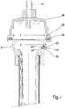
- Figure 1 shows a part of a longitudinal section through a conventional teat rubber 1, which is placed on a teat 2 of an udder 3.
- the teatcup liner 1 has a teatcup liner head 4 which merges into a teatcup rubber shaft 6 of a tube part which has a reduced diameter.
- the teat rubber 1 is also designed with an oblique closure 8, which creates a vacuum seal through a folding thin-wall area 10 of the teat rubber 1. Details of this concept are in the EP 1 119 235 and the EP 1 219 166 explained.
- a flange-like head sleeve 12 is formed, which with the outer circumference of the Teat rubber shaft 6 forms an annular space 14 into which an end section of a cup sleeve 16 is immersed.
- This is - as explained at the beginning - with its other one, in Figure 1 not visible end section in contact with a clamping bead of the teat rubber 1, so that the teat rubber 1 is clamped in the teat cup sleeve 16.
- an air inlet nozzle which is referred to below as nozzle 18, is formed in the teat rubber head 4 pointing toward the udder 3.
- the structure of the nozzle 18 shown corresponds to the solution according to the invention.
- the Figure 1 is only intended to clarify the position at which nozzles of any type are conventionally arranged. It can be seen in this illustration that the nozzle 18 is covered by the udder 3 and there is therefore a risk that on the one hand the nozzle opening is sealed or that it can be closed by means of dirt.
- FIG Figure 2 shows in principle the same structure, the nozzle is now positioned according to the invention. It can be seen that this is arranged at a distance from the udder 3 approximately in the area in which the teat rubber head 4 has its largest diameter D. Specifically, the nozzle 18 is shown in FIG Figure 2 arranged below this maximum outer diameter D of the teat rubber head 4, that is to say offset to the teat rubber shaft 6. An axis 20 of the nozzle 18 runs essentially at right angles to the teat rubber wall.
- this nozzle 18 has a dome-shaped dome 22 in which the nozzle bore is formed.
- the apex of this dome 22 protrudes beyond the outer circumference of the teat rubber 1.
- the apex of the dome 22 extends outward in the radial direction over the envelope cylinder of the teat rubber head 4 with the diameter D indicated by the broken line. This ensures that this dome 22 is easily accessible for cleaning.
- the specific structure of the nozzle 18 is explained in more detail below.
- Figure 3 shows a variant in which the nozzle 18 is fixed by means of a metallic plug-in sleeve 24.
- a receiving bore 26 is formed in the teat rubber wall, which is widened towards the outside to form a flange receptacle 28.
- This is shaped in such a way that the nozzle seat is slightly recessed into the teat rubber head wall and therefore the nozzle does not accidentally slip when a rinsing device / rinsing cap is attached or can be pulled out.
- the recess depth s is preferably between 0.5 and 1.5 mm.
- the nozzle 18 has two positioning flanges 30, 32 spaced apart from one another, the positioning flange 30 on the dome side merging conically into the dome 22.
- the flange receptacle 28 is designed such that it receives the positioning flange 30 at least in sections and is sunk as described above.
- the nozzle 18 (this applies to all of the exemplary embodiments) is made of a highly elastic material, for example silicone with a Shore A hardness of approximately 60, and can therefore be inserted very easily into the receiving bore 26 by elastic deformation. Subsequently, the metallic plug-in sleeve 24 is then used for fixing, so that the two positioning flanges 30, 32 are arranged on both sides of the teat rubber wall and the outer circumference of the nozzle 18 is prestressed with surface pressure against the circumferential wall of the receiving bore 26. This mounting position is in Figure 4 shown.
- FIGS. 3 and 4th also show a section of a flushing cap 34, which can be designed, for example, as a standard flushing cap or clearwashing flushing cap.
- This flushing cap 34 is connected to a cleaning device of the milking system via a hose connector 35 and a hose, not shown.
- a circumferential seal 36 is formed with a sealing lip 38 which, when the flushing cap is fitted, lies sealingly against the outer circumferential area of the teat rubber head 4.
- the inner diameter d of the sealing lip 38 is smaller than the diameter D of the teat rubber head 4, so that the sealing lip 38 slides over the dome 22 of the nozzle 18 with pretension when the rinsing cap 34 is placed on, and thus mechanically wipes off deposits / dirt and at least the dome 22 elastically deformed.
- Figure 5 shows the constellation according to Figure 4 when putting on a standard flushing cap 34, which is designed without a seal. It can be seen that in this case the inner diameter d of the flushing cap 34 is selected such that it also comes into wiping contact with the mandrel 22 of the nozzle 18. Accordingly, the diameter d is selected to be the same size or slightly smaller than the outer diameter D of the teat rubber head 4.
- FIG. 6 shows a constellation in which the flushing cap 34 is designed as a clearwashing flushing cap, the geometry of which is selected somewhat differently from that of the previously described flushing caps 34.
- a teat rubber head 4 suitable for such a system can be designed with an approximately cylindrical jacket section 40, which is then somewhat stepped down and also connected in the broadest sense to a ring sleeve-like head sleeve 12.
- the nozzle 18 is accommodated in the cylindrical jacket section 40, which is not arranged obliquely, as in the previously described exemplary embodiments, but in the radial direction with respect to the teat rubber axis 42.
- the illustrated flushing cap 34 also has a seal 36 with a sealing lip 38, the inside diameter d of which is somewhat smaller than the outside diameter D of the cylindrical casing section 40, so that when the flushing cap 34 is placed on, the sealing lip 38 comes into contact with the dome 22 of the nozzle 18.
- Figure 7 shows an individual representation of a preferred embodiment of a nozzle 18 according to the invention.
- the nozzles 18 according to the invention are preferably formed from highly elastic silicone.
- the material should have a Shore A hardness in the range between 50 to 70, preferably a Shore A hardness of about 60.
- the nozzle 18 shown has an approximately cylindrical base body 44 with the two positioning flanges 30, 32 projecting radially to the axis 20.
- the nozzle 18 has a stepped nozzle bore 46 which is stepped back in the direction of the rounded dome 22 of the nozzle 18.
- the actual nozzle opening 47 is formed in this dome 22, the diameter of which is substantially smaller than that of the nozzle bore 46.
- the annular shoulder 48 formed by a radial step can serve, for example, as a stop surface for the plug-in sleeve 24 explained above. In principle, this radial shoulder 48 can also be used to place an insertion tool, via which the nozzle 18 is inserted into the receiving bore 26 of the teat rubber head 4. Since the diameter of the radial shoulder 48 is substantially larger than that of the nozzle opening 47, it cannot be damaged when it is inserted.
- the positioning flange 30 on the dome side is formed with a conical end face, so that an almost continuous transition to the dome 22 is formed.
- This nozzle 18 can be manufactured, for example, by injection molding or the like.
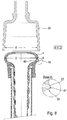
- Figure 8 shows a greatly simplified embodiment with, for example, a standard rinsing cap 34 and a nozzle 18 formed integrally on the teat rubber head 4.
- the dome 22 of the nozzle 18 is formed by a membrane-like, curved, highly elastic jacket section of the teat rubber head 4.
- the nozzle opening 47 opens into this dome 22.
- the nozzle bore 46 which is radially enlarged in comparison, is then in accordance with FIG Figure 8 formed in the wall of the teatcup liner 4. In such an embodiment, the assembly effort is reduced compared to the embodiment described above.
- Figure 9 shows a variant of the embodiment according to the Figures 3 and 4th .
- the variant according to FIG Figure 9 the nozzle 18 is arranged in the area with the largest diameter D of the teat rubber head 4.
- the flushing cap 34 is, for example, according to the exemplary embodiments according to FIGS Figures 3 and 4th educated. Accordingly, the diameter d of the sealing lip 38 is significantly smaller than the diameter D of the teat rubber head 4, so that when the rinsing cap 34 is put on, dirt is wiped off from the dome 22 of the nozzle 18.
- This stripping can be accompanied by an elastic deformation of the nozzle 18 when the rinsing cap 34 is put on in accordance with the above-described exemplary embodiments.
- the nozzle 18 is made of silicone.
- other materials can be provided that are relatively soft and elastic compared to the conventional solutions, so that stripping / deforming is made possible in a simple manner.
- a teat rubber and a nozzle suitable for such a teat rubber which is made of a highly elastic material that allows stripping of dirt by elastic deformation.
Landscapes
- Life Sciences & Earth Sciences (AREA)
- Animal Husbandry (AREA)
- Environmental Sciences (AREA)
- Cleaning In General (AREA)
- Medical Preparation Storing Or Oral Administration Devices (AREA)
- Dental Tools And Instruments Or Auxiliary Dental Instruments (AREA)
- Acyclic And Carbocyclic Compounds In Medicinal Compositions (AREA)
Description
- Die Erfindung betrifft einen Zitzengummi gemäß dem Oberbegriff des Patentanspruches 1 und eine für einen derartigen Zitzengummi geeignete Düse.
- Ein gattungsgemäßer Zitzengummi ist beispielsweise aus der Patentfamilie
DE 10 2006 026 271 A1 und den ZusatzanmeldungenDE 10 2006 040 079 A1 undDE 10 2007 053 230 A1 bekannt. - Diese Druckschriften offenbaren jeweils einen Zitzengummi mit einem Zitzengummikopf, der eine Einführöffnung für eine Zitze aufweist. An den Zitzengummikopf schließt sich ein Schlauchteil zur Aufnahme der Zitze an. Der Zitzengummikopf ist mit einer Kopfmuffe ausgebildet, die im montierten Zustand einen Melkbecher umgreift, dessen anderer Endabschnitt an einer Spannwulst des Schlauchteils anliegt, um den Zitzengummi mit einer Spannung zu beaufschlagen.
- Die prinzipielle Anordnung eines derartigen Zitzengummis mit Bezug zum Melkbecher ist in den Druckschriften
EP 1 119 235 B1 undEP 1 219 166 A2 offenbart. - Bei dem eingangs genannten Stand der Technik ist im Zitzengummikopf eine Lufteinlassdüse ausgebildet, über die ein Kopfinnenraum zur Atmosphäre hin belüftet ist. Durch diese Belüftung ist gewährleistet, dass sich im Zitzengummikopf kein übermäßiges Vakuum ausbilden kann. Die bekannten Vorteile für den Lufteinlass beim Melken am Zitzengummi sind u.a. ein besserer Milchtransport und kein Rückspray vom Sammelstück. Des Weiteren wird durch die Kombination mit dem von den Anmeldern entwickelten tiergerechten Entlastungssystem in der Massagephase durch die zugeführte Luft die gewünschte Vakuumentlastung bewirkt.
- Ein Problem bei derartigen Lösungen besteht darin, dass die Lufteinlassdüse einen relativ geringen Öffnungsdurchmesser von etwa 0,6 bis 1,0 mm aufweist. Es besteht die Gefahr, dass sich diese Düsenöffnung beim Melken beispielsweise durch Kontakt mit dem Euter oder mit Hautfalten zusetzt und nicht mehr ordnungsgemäß funktioniert. Beim Einsatz eines derartigen Melkzeugs ist somit nach jedem Melken darauf zu achten, dass bei der üblichen Reinigung der Zitzengummi auch die Lufteinlassdüse gesäubert wird. Dies kann beispielsweise manuell durch Abspritzen oder Abbürsten der Düsenmündung erfolgen.
- In der
DE 10 2008 027 277 A1 ist eine Lösung vorgeschlagen, bei der zur Reinigung eines Zitzengummis eine Spülkappe auf den Zitzengummikopf aufgesetzt wird, so dass der vom Zitzengummikopf umgriffene Kopfinnenraum und auch Umfangsbereiche des Zitzengummis mit einer Reinigungsflüssigkeit gereinigt werden können. - In dieser Druckschrift der Anmelder wird vorgeschlagen, die Spülkappe mit einer umlaufenden Dichtlippe auszubilden, die den Umfangsbereich des Zitzengummis nach Außen hin abdichtet, so dass der Kopfinnenraum und/oder der betreffende Außenumfangsabschnitt des Zitzengummikopfes gereinigt werden kann. Bei dieser Lösung ist die Düse so positioniert, dass sie in dem von der Dichtlippe abgeschlossenen Raum liegt, so dass beim Reinigen des Zitzengummis die Düse umspült und somit mitgereinigt wird.
- Es zeigte sich jedoch, dass sich die Düse auch bereits während des Melkvorganges zusetzen kann, so dass eine manuelle Reinigung vor dem oben beschriebenen Spülen durch die Spülkappe erfolgen muss, um die ordnungsgemäße Funktion des Melkzeugs zu gewährleisten. Bei den bekannten Zitzengummis verwendet der Melker eine Art Nagel, um den Düsenquerschnitt zu öffnen. Dies ist während des Melkvorgangs relativ umständlich durchführbar und setzt eine große Erfahrung voraus.
- Demgegenüber liegt der Erfindung die Aufgabe zugrunde, einen Zitzengummi mit Lufteinlassdüse zu schaffen, bei dem die Lufteinlassdüse mit geringem Aufwand gereinigt werden kann. Des Weiteren liegt der Erfindung die Aufgabe zugrunde, eine geeignete Düse zu schaffen.
- Diese Aufgabe wird durch einen Zitzengummi mit den Merkmalen des Patentanspruches 1 gelöst. Im Hinblick auf die Düse wird die Erfindung durch die Merkmale des nebengeordneten Patentanspruches 14 gelöst.
- Vorteilhafte Weiterbildungen der Erfindung sind Gegenstand der Unteransprüche.
- Erfindungsgemäß ist an einem Zitzengummikopf eines Zitzengummis eine Düse aus einem elastischen Material ausgebildet, die über die Außenkontur des Zitzengummis hervorsteht, mit anderen Worten gesagt, aus diesem auskragt. Durch dieses Auskragen ist zum einen gute Zugänglichkeit gewährleistet. Zum anderen ist durch die Verwendung eines elastischen Materials ein Reinigen oder Abstreifen der Ablagerungen durch den Finger/Fingernagel ohne zusätzliche Hilfsmittel möglich. Das elastische Material ist so gewählt, dass sich zumindest der auskragende Bereich der Düse beim Reinigen manuell elastisch deformieren lässt, so dass die Verschmutzungen/Verkrustungen einfach gelöst werden können.
- Bei einem besonders bevorzugten Ausführungsbeispiel der Erfindung ist die Düse in einem Bereich angeordnet, an dem eine Spülkappe zum Reinigen des Zitzengummis aufgesetzt wird, so dass durch diesen Aufsetzvorgang die Verschmutzung der Düse "abgestriffen" wird. Dieses Abstreifen wird durch die Ausbildung der Düse aus dem elastischen Material und die damit einhergehende Deformation unterstützt.
- Üblicher Weise sind derartige Spülkappen mit einer Dichtkante oder Dichtlippe ausgebildet, die dann beim Aufsetzen in direkten Abstreifkontakt mit der Düse aus elastischem Material gelangen.
- Bei einem bevorzugten Ausführungsbeispiel der Erfindung ist die Düse im Bereich des größten Umfangs des Zitzengummikopfes angeordnet, so dass die Düse zum einen beim Melken nicht durch das Euter oder Hautfalten abgedeckt werden kann und zum anderen für den Melker gut erreichbar ist, so dass er die Düse mit dem Finger verformen (durchwalken) kann, um die etwaige Verschmutzungsreste zu lösen. Zum anderen ist durch diese Positionierung im Bereich des größten Umfangs gewährleistet, dass die Spülkappe in mechanischen Kontakt mit dem auskragenden Endabschnitt der Düse gelangt.
- Dabei wird es besonders bevorzugt, wenn die Düse zum Schlauchteil hin versetzt mit Bezug zum größten Hüllkreis-/zylinder des Zitzengummikopfes angeordnet ist.
- Bei einem Ausführungsbeispiel wird es bevorzugt, wenn die Düse auswechselbar im Zitzengummi gehalten ist.
- Das Einsetzen und Positionieren der Düse ist besonders einfach, wenn diese zwei zu einander beabstandete Positionierflansche hat, deren Abstand in etwa der Wandstärke des Zitzengummikopfes in diesem Bereich entspricht, so dass die Zitzengummiwandung zwischen den beiden Positionierflanschen verläuft und somit die Düse zuverlässig lagepositioniert ist.
- Bei einem derartigen Ausführungsbeispiel wird es bevorzugt, wenn der außen liegende Positionierflansch zum Endabschnitt der Düse, d.h. zu deren Düsenöffnung hin, etwa kegelförmig oder verrundet ausgeführt ist.
- Vorzugsweise wird an der Außenwandung des Zitzengummikopfs eine versenkte Flanschaufnahme ausgebildet, so dass der Sitz, beispielsweise der außenliegende Positionierflansch entsprechen versenkt ist, so dass die Düse beim Aufsetzen der Spüleinrichtung nicht verrutschen oder herausgezogen werden kann. Die Einsenkung kann etwa 0,5 bis 1,5 mm betragen.
- Die Positionierung der Düse lässt sich weiter verbessern, wenn diese mittels einer Steckhülse im Zitzengummikopf festgelegt ist.
- Die Herstellung des Zitzengummis ist besonders einfach, wenn die Düse einstückig mit dem Zitzengummi ausgebildet ist.
- Erfindungsgemäß wird es bevorzugt, wenn diese Düse aus Silikon oder einem vergleichbaren Material hergestellt ist. Die Shore A-Härte sollte (bestimmt nach dem Shore A-Härte-Prüfverfahren) im Bereich zwischen 50 und 70, vorzugsweise 60 betragen.
- Erfindungsgemäß wird somit ein Zitzengummi geschaffen, der:
- beim Melken nicht verschmutzt,
- beim Melken nicht durch das Euter oder Hautfalten verschlossen werden kann,
- mechanisch leicht mit dem Finger ohne Werkzeug zu reinigen ist und
- bei jedem Spülvorgang bei allen gängigen Spülaufnahmen gereinigt wird.
- Weitere Vorteile der Erfindung werden gesehen in:
- der hochelastischen Düse für den Lufteinlass mit einem nach außen gewölbten Dom (Endabschnitt) und integrierter Bohrung, vorzugsweise am höchsten Punkt (Scheitel des Doms),
- Verwendung eines hochelastischen Materials, vorzugsweise Silikon,
- Positionierung der Düse im Zitzengummi derart, dass beim regelmäßigen Aufstecken auf die Spüleinrichtung (Spülkappe) der elastische, nach außen gewölbte Dom eine mechanische Verformung erfährt, die sicherstellt, dass die Düsenbohrung geöffnet bleibt bzw. evtl. vorhandene Schmutzpartikel gelöst werden,
- einem Tiefersetzen der Düse in der Form, dass nur der Dom die Reinigungseinrichtung streift, so dass ein Herausrutschen der Düse aus dem Zitzengummi verhinderbar ist,
- eine alternativen Ausgestaltung der Düse einstückig mit dem Zitzengummi und
- in der kuppelförmigen Ausgestaltung der Düse, so dass diese auch während des Melkens mit dem Finger bzw. Fingernagel gereinigt oder kontrolliert werden kann.
- Die Düse für einen derartigen Zitzengummi wird vorzugsweise mit einem abgestuften Innendurchmesser ausgebildet, der ein Einschieben der Düse mittels eines Werkzeugs in den Zitzengummi ermöglicht, ohne die Düsenkuppe/ den Düsendom zu beschädigen.
- Wie erläutert, kann die Befestigung durch eine zusätzliche Steckhülse verbessert werden. Diese wird vorzugsweise aus Metall gefertigt.
- Die Erfindung wird im Folgenden anhand schematischer Zeichnungen näher erläutert. Es zeigen:
-
Figur 1 einen aus dem Stand der Technik bekannten Zitzengummikopf; -
Figur 2 einen erfindungsgemäßen Zitzengummikopf mit einer hochelastischen Düse; -
Figur 3 ein Ausführungsbeispiel des Zitzengummikopfes ausFigur 2 mit Steckhülse; -
Figur 4 das Ausführungsbeispiel gemäßFigur 3 im montierten Zustand; -
Figur 5 ein Ausführungsbeispiel mit einer für eine radiale Abdichtung mittels einer Standard-Spülkappe geeigneten Düsenposition; -
Figur 6 ein Ausführungsbeispiel der Erfindung mit einer Düsenposition, die für eine Clearwash-Spülaufnahme geeignet ist; -
Figur 7 eine Schnittdarstellung einer hochelastischen Düse für einen Zitzengummi gemäß den vorbeschriebenen Ausführungsbeispielen; -
Figur 8 eine einstückig mit dem Zitzengummi ausgebildete Düse und -
Figur 9 ein weiteres Ausführungsbeispiel für einen Zitzengummi mit einer erfindungsgemäßen Düse. -
Figur 1 zeigt einen Teil eines Längsschnittes durch einen herkömmlichen Zitzengummi 1, der auf eine Zitze 2 eines Euters 3 aufgesetzt ist. Der Zitzengummi 1 hat einen Zitzengummikopf 4, der in einen im Durchmesser verringerten Zitzengummischaft 6 eines Schlauchteils übergeht. Der Zitzengummi 1 ist des Weiteren mit einem Schrägabschluss 8 ausgeführt, der im Entlastungstakt durch einen sich einfaltenden Dünnwandbereich 10 des Zitzengummis 1 einen Abschluss zum Vakuum herstellt. Einzelheiten dieser Konzeption sind in derEP 1 119 235 und derEP 1 219 166 erläutert. - Im Übergangsbereich zwischen dem Zitzengummikopf 4 und dem Zitzengummischaft 6 ist eine flanschartige Kopfmuffe 12 ausgebildet, die mit dem Außenumfang des Zitzengummischaftes 6 einen Ringraum 14 ausbildet, in den ein Endabschnitt einer Becherhülse 16 eintaucht. Diese ist-wie eingangs erläutert - mit ihrem anderen, in
Figur 1 nicht sichtbaren Endabschnitt in Anlage an einer Spannwulst des Zitzengummis1, so dass der Zitzengummi 1 in die Melkbecherhülse 16 eingespannt ist. Bei der herkömmlichen Lösung ist im Zitzengummikopf 4 zum Euter 3 hinweisend eine Lufteinlassdüse ausgebildet, die im Folgenden als Düse 18 bezeichnet wird. Der Aufbau der dargestellten Düse 18 an sich entspricht der erfindungsgemäßen Lösung. DieFigur 1 soll lediglich verdeutlichen, an welcher Position herkömmlicher Weise Düsen -jedweder Bauart - angeordnet sind. Man erkennt in dieser Darstellung, dass die Düse 18 vom Euter 3 überdeckt ist und somit die Gefahr besteht, dass zum einen die Düsenöffnung abgedichtet ist oder aber mittels Verschmutzungen verschlossen werden kann. -
Figur 2 zeigt im Prinzip den gleichen Aufbau, wobei die Düse nunmehr erfindungsgemäß positioniert ist. Man erkennt, dass diese im Abstand zum Euter 3 etwa in dem Bereich angeordnet ist, in dem der Zitzengummikopf 4 seinen größten Durchmesser D aufweist. Konkret ist die Düse 18 in der Darstellung gemäßFigur 2 unterhalb dieses maximalen Außendurchmessers D des Zitzengummikopfes 4 angeordnet, d.h. hin zum Zitzengummischaft 6 versetzt angeordnet. Eine Achse 20 der Düse 18 verläuft dabei im Wesentlichen rechtwinklig zur Zitzengummiwandung. - Wie im Folgenden noch näher erläutert wird, hat diese Düse 18 einen kuppelförmigen Dom 22, in dem die Düsenbohrung ausgebildet ist. Der Scheitel dieses Doms 22 kragt über den Außenumfang des Zitzengummis 1 hinaus. Mit anderen Worten gesagt, der Scheitel des Doms 22 erstreckt sich über den gestrichelt angedeuteten Hüllzylinder des Zitzengummikopfs 4 mit dem Durchmesser D in Radialrichtung nach außen heraus. Dadurch ist sichergestellt, dass dieser Dom 22 zur Reinigung gut zugänglich ist. Der konkrete Aufbau der Düse 18 wird im Folgenden noch näher erläutert.
-
Figur 3 zeigt eine Variante, bei der die Fixierung der Düse 18 mittels einer metallischen Steckhülse 24 erfolgt. In der Zitzengummiwandung ist eine Aufnahmebohrung 26 ausgebildet, die nach außen hin zu einer Flanschaufnahme 28 erweitert ist. Diese ist so geformt, dass der Düsensitz etwas in die Zitzengummikopfwandung versenkt ist und somit die Düse beim Ansetzen einer Spüleinrichtung/Spülkappe nicht versehentlich verrutschen oder herausgezogen werden kann. Die Einsenktiefe s beträgt vorzugsweise zwischen 0,5 und 1,5 mm. Die Düse 18 hat - wie im Folgenden noch näher erklärt wird - zwei zueinander beabstandete Positionierflansche 30, 32, wobei der domseitige Positionierflansch 30 kegelförmig in den Dom 22 übergeht. Die Flanschaufnahme 28 ist so ausgebildet, dass sie den Positionierflansch 30 zumindest abschnittsweise aufnimmt und dieser wie oben beschrieben versenkt ist. - Die Düse 18 (dies gilt für alle Ausführungsbeispiele) ist aus einem hochelastischen Material, beispielsweise Silikon mit einer Shore A-Härte von etwa 60 ausgebildet und kann somit sehr einfach durch elastische Verformung in die Aufnahmebohrung 26 eingesetzt werden. Im Anschluss daran wird dann zur Fixierung die metallische Steckhülse 24 eingesetzt, so dass die beiden Positionierflansche 30, 32 beidseitig der Zitzengummiwandung angeordnet sind und der Außenumfang der Düse 18 mit Flächenpressung gegen die Umfangswandung der Aufnahmebohrung 26 vorgespannt ist. Diese Montageposition ist in
Figur 4 dargestellt. - Die
Figuren 3 und4 zeigen auch einen Schnitt einer Spülkappe 34, die beispielsweise als Standard-Spülkappe oder Clearwash-Spülkappe ausgeführt sein kann. Diese Spülkappe 34 ist über einen Schlauchstutzen 35 und einen nicht dargestellten Schlauch an eine Reinigungseinrichtung der Melkanlage angeschlossen. Im Innenumfangsbereich der Spülkappe 34 ist eine umlaufende Dichtung 36 mit einer Dichtlippe 38 ausgebildet, die bei aufgesetzter Spülkappe dichtend am Außenumfangsbereich des Zitzengummikopfes 4 anliegt. Der Innendurchmesser d der Dichtlippe 38 ist dabei geringer als der Durchmesser D des Zitzengummikopfes 4, so dass die Dichtlippe 38 beim Aufsetzen der Spülkappe 34 mit Vorspannung über den Dom 22 der Düse 18 hinweg gleitet und somit mechanisch Ablagerungen/Verschmutzungen abstreift und zumindest den Dom 22 elastisch deformiert. -
Figur 5 zeigt die Konstellation gemäßFigur 4 bei Aufsetzen einer Standard-Spülkappe 34, die ohne Dichtung ausgeführt ist. Man erkennt, dass in diesem Fall der Innendurchmesser d der Spülkappe 34 so gewählt ist, dass auch er in Abstreifkontakt mit dem Dom 22 der Düse 18 gelangt. Dementsprechend ist der Durchmesser d gleich groß oder etwas geringer als der Außendurchmesser D des Zitzengummikopfes 4 gewählt. -
Figur 6 zeigt eine Konstellation, bei der die Spülkappe 34 als Clearwash-Spülkappe ausgebildet ist, deren Geometrie etwas anders als diejenige der vorbeschriebenen Spülkappen 34 gewählt ist. Ein für ein derartiges System geeigneter Zitzengummikopf 4 kann mit einem etwa zylinderförmigen Mantelabschnitt 40 ausgeführt sein, an den sich dann etwas zurückgestuft die ebenfalls im weitesten Sinn ringzylinderartige Kopfmuffe 12 anschließt. In dem zylinderförmigen Mantelabschnitt 40 ist die Düse 18 aufgenommen, die dabei nicht schräg, wie bei den zuvor beschriebenen Ausführungsbeispielen sondern in Radialrichtung mit Bezug zur Zitzengummiachse 42 angeordnet ist. Die inFigur 6 dargestellte Spülkappe 34 hat ebenfalls eine Dichtung 36 mit einer Dichtlippe 38, deren Innendurchmesser d etwas kleiner als der Außendurchmesser D des zylindrischen Mantelabschnittes 40 ausgebildet ist, so dass beim Aufsetzen der Spülkappe 34 die Dichtlippe 38 in Kontakt mit dem Dom 22 der Düse 18 gelangt. -
Figur 7 zeigt eine Einzeldarstellung eines bevorzugten Ausführungsbeispiels einer erfindungsgemäßen Düse 18. Wie vorstehend erläutert, sind die erfindungsgemäßen Düsen 18 vorzugsweise aus hochelastischem Silikon ausgebildet. Das Material sollte eine Shore A-Härte im Bereich zwischen 50 bis 70, vorzugsweise eine Shore A-Härte von etwa 60 aufweisen. - Die in
Figur 7 gezeigte Düse 18 hat einen in etwa zylinderförmigen Grundkörper 44 mit den beiden in Radialrichtung zur Achse 20 auskragenden Positionierflanschen 30, 32. Die Düse 18 hat eine gestufte Düsenbohrung 46, die in Richtung zu dem verrundeten Dom 22 der Düse 18 zurückgestuft ist. In diesem Dom 22 ist die eigentliche Düsenöffnung 47 ausgebildet, deren Durchmesser wesentlich geringer als derjenige der Düsenbohrung 46 ist. Die durch eine Radialstufe ausgebildete Ringschulter 48 kann beispielsweise als Anschlagfläche für die vorstehend erläuterte Steckhülse 24 dienen. Prinzipiell kann diese Radialschulter 48 auch zur Anlage eines Einsetzwerkzeuges verwendet werden, über das die Düse 18 in die Aufnahmebohrung 26 des Zitzengummikopfes 4 eingeschoben wird. Da der Durchmesser der Radialschulter 48 wesentlich größer als derjenige der Düsenöffnung 47, kann diese beim Einsetzen nicht beschädigt werden. - Der domseitige Positionierflansch 30 ist mit einer kegeligen Stirnfläche ausgebildet, so dass ein nahezu stetiger Übergang zum Dom 22 ausgebildet ist.
- Diese Düse 18 kann beispielsweise durch Spritzgießen oder dergleichen hergestellt werden.
-
Figur 8 zeigt ein stark vereinfachtes Ausführungsbeispiel mit beispielsweise einer Standard-Spülkappe 34 und einer einstückig am Zitzengummikopf 4 ausgebildeten Düse 18. Dabei ist der Dom 22 der Düse 18 durch einen membranartigen, ausgewölbten, hochelastischen Mantelabschnitt des Zitzengummikopfes 4 ausgebildet. In diesem Dom 22 mündet die Düsenöffnung 47. Die demgegenüber radial vergrößerte Düsenbohrung 46 ist dann gemäßFigur 8 in der Wandung des Zitzengummis 4 ausgebildet. Bei einem derartigen Ausführungsbeispiel ist der Montageaufwand gegenüber dem vorstehend beschriebenen Ausführungsbeispiel verringert. -
Figur 9 zeigt eine Variante des Ausführungsbeispiels gemäß denFiguren 3 und4 . Im Unterschied zu diesen Ausführungsbeispielen ist bei der Variante gemäßFigur 9 die Düse 18 in dem Bereich mit dem größten Durchmesser D des Zitzengummikopfes 4 angeordnet. Die Spülkappe 34 ist beispielsweise nach den Ausführungsbeispielen gemäß denFiguren 3 und4 ausgebildet. Dementsprechend ist der Durchmesser d der Dichtlippe 38 deutlich geringer als der Durchmesser D des Zitzengummikopfes 4 ausgebildet, so dass beim Aufsetzen der Spülkappe 34 Verschmutzungen vom Dom 22 der Düse 18 abgestriffen werden. Dieses Abstreifen kann beim Aufsetzen der Spülkappe 34 gemäß den vorbeschriebenen Ausführungsbeispielen mit einer elastischen Verformung der Düse 18 einhergehen. - Bei den zuvor beschriebenen Ausführungsbeispielen ist die Düse 18 aus Silikon gefertigt. Prinzipiell können auch andere Materialien vorgesehen werden, die gegenüber den herkömmlichen Lösungen relativ weich und elastisch ausgebildet sind, so dass ein Abstreifen/Verformen auf einfache Weise ermöglicht ist.
- Offenbart sind ein Zitzengummi und eine für einen derartigen Zitzengummi geeignete Düse, die aus einem hochelastischen Material gefertigt ist, das ein Abstreifen von Schmutz durch ein elastisches Deformieren ermöglicht.
-
- 1
- Zitzengummi
- 2
- Zitze
- 3
- Euter
- 4
- Zitzengummikopf
- 6
- Zitzengummischaft
- 8
- Schrägabschluss
- 10
- Dünnwandbereich
- 12
- Kopfmuffe
- 14
- Ringraum
- 16
- Melkbecherhülse
- 18
- Düse
- 20
- Achse
- 22
- Dom
- 24
- Steckhülse
- 26
- Aufnahmebohrung
- 28
- Flanschaufnahme
- 30
- Positionierflansch
- 32
- Positionierflansch
- 34
- Spülkappe
- 35
- Schlauchstutzen
- 36
- Dichtung
- 38
- Dichtlippe
- 40
- Mantelabschnitt
- 42
- Zitzengummiachse
- 44
- Grundkörper
- 46
- Düsenbohrung
- 47
- Düsenöffnung
- 48
- Radialschulter
Claims (15)
- Zitzengummi mit einem Zitzengummikopf (4), in dem eine Düse (18) vorgesehen ist, wobei die Düse (18) aus dem Zitzengummikopf (4) nach außen, über die Zitzengummikopfkontur hinaus auskragt, dadurch gekennzeichnet, dass die Düse (18) aus einem zur Reinigung elastisch deformierbaren Material gebildet ist, so dass ein Abstreifen und Deformieren der Düse (18) manuell mit dem Finger ermöglicht ist.
- Zitzengummi nach Patentanspruch 1, wobei die Düse (18) in einem Bereich angeordnet ist, in dem eine Spülkappe (34) zum Reinigen des Zitzengummis (1) aufgesetzt wird, so dass ein Abstreifen und Deformieren der Düse (18) auch durch das Aufsetzen der Spülkappe (34) ermöglicht ist.
- Zitzengummi nach Patentanspruch 1 oder 2, wobei die Düse (18) im Bereich des größten Durchmessers (D) des Zitzengummikopfes (4) angeordnet ist.
- Zitzengummi nach Patentanspruch 3, wobei die Düse (18) über den Hüllzylinder des Zitzengummikopfes (4) hinaus auskragt.
- Zitzengummi nach Patentanspruch 3 oder 4, wobei die Düse (18) etwas zu einem Zitzengummischaft (6) hin versetzt ist.
- Zitzengummi nach einem der vorhergehenden Patentansprüche, wobei ein auskragender Endabschnitt der Düse (18) zu einem Dom (22) verrundet ist.
- Zitzengummi nach einem der vorhergehenden Patentansprüche, wobei die Düse (18) auswechselbar im Zitzengummikopf (4) gehalten ist.
- Zitzengummi nach Patentanspruch 7, wobei die Düse (18) zwei zu einander beabstandete Positionierflansche (30, 32) hat, zwischen denen ein Teil der Zitzengummiwandung aufgenommen ist.
- Zitzengummi nach Patentanspruch 8, wobei ein außen liegender Positionierflansch (30) zum Dom (22) der Düse (18) hin kegelig ausgebildet ist.
- Zitzengummi nach einem der vorhergehenden Patentansprüche, wobei an einer Außenwandung des Zitzengummikopfs (4) eine versenkte Flanschaufnahme (28) für einen Sitz der Düse (18), vorzugsweise für einen außenliegenden Positionierflansch (30) ausgebildet ist, wobei die Senktiefe (s) vorzugsweise im Bereich zwischen 0,5mm und 1,5mm beträgt.
- Zitzengummi nach Patentanspruch 7, 8, 9 oder 10 mit einer Steckhülse (24) zur Befestigung der Düse (18).
- Zitzengummi nach einem der Patentansprüche 1 bis 6, wobei die Düse (18) einstückig am Zitzengummikopf (4) ausgebildet ist.
- Zitzengummi nach einem der vorhergehenden Patentansprüche, wobei die Düse (18) aus Silikon, vorzugsweise mit einer Shore A-Härte von 50 bis 70, vorzugsweise 60 ausgebildet ist.
- Düse für einen Zitzengummi (1) gemäß einem der vorhergehenden Patentansprüche, dadurch gekennzeichnet, dass diese aus einem zur Reinigung elastisch deformierbaren Material ausgebildet ist, so dass ein Abstreifen und Deformieren der Düse (18) manuell mit dem Finger ermöglicht ist.
- Düse nach Patentanspruch 14, wobei diese zwei zu einander beabstandete Positionierflansche (30, 32) hat, deren Flanschabstand der Wandstärke des Zitzengummikopfes (4) entspricht, wobei vorzugsweise der düsenöffnungsseitige Endabschnitt zu einem Dom (22) verrundet ist.
Applications Claiming Priority (3)
| Application Number | Priority Date | Filing Date | Title |
|---|---|---|---|
| DE102013111544 | 2013-10-18 | ||
| DE201310114987 DE102013114987A1 (de) | 2013-10-18 | 2013-12-30 | Zitzengummi und Düse |
| PCT/EP2014/072330 WO2015055821A1 (de) | 2013-10-18 | 2014-10-17 | Zitzengummi und düse |
Publications (2)
| Publication Number | Publication Date |
|---|---|
| EP3057407A1 EP3057407A1 (de) | 2016-08-24 |
| EP3057407B1 true EP3057407B1 (de) | 2020-03-18 |
Family
ID=52775008
Family Applications (1)
| Application Number | Title | Priority Date | Filing Date |
|---|---|---|---|
| EP14786184.3A Active EP3057407B1 (de) | 2013-10-18 | 2014-10-17 | Zitzengummi und düse |
Country Status (7)
| Country | Link |
|---|---|
| US (1) | US10681896B2 (de) |
| EP (1) | EP3057407B1 (de) |
| JP (1) | JP6494043B2 (de) |
| CN (1) | CN105848472B (de) |
| DE (1) | DE102013114987A1 (de) |
| NZ (1) | NZ719144A (de) |
| WO (1) | WO2015055821A1 (de) |
Families Citing this family (7)
| Publication number | Priority date | Publication date | Assignee | Title |
|---|---|---|---|---|
| DE102014101615A1 (de) | 2014-02-10 | 2015-08-13 | Happel WDA Besitz GbR (vertretungsberechtigter Gesellschafter: Werner Happel, 87654 Friesenried) | Zitzengummi |
| DE102017123166A1 (de) | 2017-10-05 | 2019-04-11 | Werner Happel | Zitzengummi |
| NL2021181B1 (nl) * | 2018-06-26 | 2020-01-06 | Hokofarm Group B V | Tepelvoering voor een melkbeker van een melkinstallatie, melkbeker en installatie voorzien daarvan, en werkwijze daarvoor |
| AU2019341969A1 (en) * | 2018-09-19 | 2021-04-15 | Tokuyama Corporation | Milking device |
| JPWO2021065570A1 (de) * | 2019-10-02 | 2021-04-08 | ||
| US20220312719A1 (en) * | 2021-03-31 | 2022-10-06 | Beco Dairy Automation Inc. | Teat Cup Liner, Apparatus Including the Same, and Methods of Making and Using the Same |
| USD1057325S1 (en) * | 2022-01-14 | 2025-01-07 | Gea Farm Technologies, Inc. | Short milk tube vent plug for a dairy animal milker unit |
Citations (7)
| Publication number | Priority date | Publication date | Assignee | Title |
|---|---|---|---|---|
| GB644168A (en) | 1948-03-17 | 1950-10-04 | Harold Walter Burry | Improvements in teat cups for milking machines |
| DE1063849B (de) | 1959-01-16 | 1959-08-20 | Utina Elektrowerk Gmbh | Zitzengummi fuer Melkbecher von Melkmaschinen |
| DE1937122A1 (de) | 1968-07-29 | 1970-01-29 | Borg Warner | Rohrfoermige Waermeuebertragungsvorrichtung |
| WO2000013489A2 (de) | 1998-09-07 | 2000-03-16 | Fritz Happel | Melkbecher |
| WO2005120217A1 (en) | 2004-06-10 | 2005-12-22 | Delaval Holding Ab | Milking devices |
| DE102006040079A1 (de) | 2006-06-02 | 2008-03-13 | Fritz Happel | Zitzengummi |
| DE102008027277A1 (de) | 2008-06-06 | 2009-12-10 | Werner Happel | Reinigungseinrichtung und Spülkappe |
Family Cites Families (29)
| Publication number | Priority date | Publication date | Assignee | Title |
|---|---|---|---|---|
| US644168A (en) * | 1899-05-17 | 1900-02-27 | Charles E Gibbs | Fruit-picker. |
| GB190007524A (en) * | 1900-04-24 | 1901-04-06 | John Perkins Jackson | Improvements in Bottles & Stoppers for Sterilized Milk and the like. |
| US2321236A (en) * | 1940-11-19 | 1943-06-08 | Parkin Victer | Nursing bottle valve |
| US3071272A (en) * | 1961-08-29 | 1963-01-01 | Forrest Maurits | Infant feeding bottle |
| DE1937122U (de) * | 1964-12-12 | 1966-04-21 | Benedikt Mueller | Luftduese fuer melkmaschinen. |
| US3476085A (en) * | 1967-12-27 | 1969-11-04 | Daniel O Noorlander | Air-vent for milking inflation |
| US4143787A (en) * | 1978-06-15 | 1979-03-13 | National Presto Industries, Inc. | Captivated over-pressure relief air vent assembly |
| US4441454A (en) * | 1980-05-28 | 1984-04-10 | Fritz Happel | Milking apparatus |
| US4651676A (en) * | 1985-12-04 | 1987-03-24 | Kupres Steven J | Silicone milking unit |
| US4756852A (en) * | 1986-08-04 | 1988-07-12 | Nuclear Packaging, Inc. | Method of installing a vent in a nuclear waste storage system |
| US5944205A (en) * | 1998-01-22 | 1999-08-31 | Lajoie; Ronald J. | Automatic air venting rigid plastic baby bottle |
| US6055931A (en) * | 1998-10-13 | 2000-05-02 | Dec International, Inc. | Clog resistant air vent plug for teatcup liner |
| US6375528B1 (en) * | 2000-04-11 | 2002-04-23 | Bombardier Motor Corporation Of America | Adjustable variable vent opening plugs for engine exhaust |
| DE10107747A1 (de) | 2000-12-26 | 2002-09-05 | Fritz Happel | Melkverfahren mittels Melkbecher mit einem zur Zitzenaufnahme bestimmten Schlauchteil mit Dünnwand-Massageflächen und Reduzierung des Vakuums im Innenraum beim Massagetakt |
| NL1033100C2 (nl) * | 2006-12-21 | 2008-06-24 | Maasland Nv | Melkbekerreinigingsinrichting en -werkwijze. |
| DE102004019728A1 (de) * | 2004-04-20 | 2005-11-17 | Werner Happel | Melkzeug |
| US7290498B2 (en) * | 2004-06-29 | 2007-11-06 | Lauren Agrisystems, Ltd. | Vent plug for milking liner |
| CA2570327C (en) * | 2004-06-29 | 2013-11-26 | Lauren Agrisystems, Ltd. | Milking liner |
| US7293527B2 (en) * | 2004-06-29 | 2007-11-13 | Lauren Agrisystems, Ltd. | Vent plug for milking liner |
| DE202006020484U1 (de) * | 2006-05-26 | 2008-10-02 | Happel, Fritz | Zitzengummi |
| DE102007053230A1 (de) * | 2006-06-02 | 2009-05-07 | Fritz Happel | Zitzengummi |
| SE530943C2 (sv) * | 2006-10-02 | 2008-10-28 | Delaval Holding Ab | Spengummi |
| WO2008131281A1 (en) * | 2007-04-20 | 2008-10-30 | Learning Curve Brands, Inc. | Drinking container lid with soft spout |
| WO2009048417A1 (en) * | 2007-10-08 | 2009-04-16 | Delaval Holding Ab | A tubular element and a method for manufacturing thereof |
| DK2229085T3 (da) * | 2008-01-14 | 2011-10-03 | Pi Design Ag | Dobbeltvægget beholder med trykudligningslåg |
| JP2010270829A (ja) | 2009-05-21 | 2010-12-02 | Ntn Corp | 油圧式オートテンショナ |
| NZ599630A (en) | 2009-12-02 | 2013-10-25 | Avon Polymer Prod Ltd | Mouthpiece-vented teat cup inflation |
| US8056505B2 (en) * | 2009-12-08 | 2011-11-15 | Lauren Agrisystems, Ltd. | Vent for milking liner |
| JP2012047297A (ja) | 2010-08-27 | 2012-03-08 | Ntn Corp | 軸受装置 |
-
2013
- 2013-12-30 DE DE201310114987 patent/DE102013114987A1/de not_active Ceased
-
2014
- 2014-10-17 WO PCT/EP2014/072330 patent/WO2015055821A1/de not_active Ceased
- 2014-10-17 JP JP2016524527A patent/JP6494043B2/ja active Active
- 2014-10-17 CN CN201480057357.1A patent/CN105848472B/zh active Active
- 2014-10-17 EP EP14786184.3A patent/EP3057407B1/de active Active
- 2014-10-17 NZ NZ719144A patent/NZ719144A/en unknown
- 2014-10-17 US US15/030,001 patent/US10681896B2/en active Active
Patent Citations (8)
| Publication number | Priority date | Publication date | Assignee | Title |
|---|---|---|---|---|
| GB644168A (en) | 1948-03-17 | 1950-10-04 | Harold Walter Burry | Improvements in teat cups for milking machines |
| DE1063849B (de) | 1959-01-16 | 1959-08-20 | Utina Elektrowerk Gmbh | Zitzengummi fuer Melkbecher von Melkmaschinen |
| DE1937122A1 (de) | 1968-07-29 | 1970-01-29 | Borg Warner | Rohrfoermige Waermeuebertragungsvorrichtung |
| WO2000013489A2 (de) | 1998-09-07 | 2000-03-16 | Fritz Happel | Melkbecher |
| US6546893B1 (en) | 1998-09-07 | 2003-04-15 | Fritz Happel | Milking cup |
| WO2005120217A1 (en) | 2004-06-10 | 2005-12-22 | Delaval Holding Ab | Milking devices |
| DE102006040079A1 (de) | 2006-06-02 | 2008-03-13 | Fritz Happel | Zitzengummi |
| DE102008027277A1 (de) | 2008-06-06 | 2009-12-10 | Werner Happel | Reinigungseinrichtung und Spülkappe |
Non-Patent Citations (2)
| Title |
|---|
| "Nylon 6", WIKIPEDIA, 8 August 2020 (2020-08-08), XP055763725, Retrieved from the Internet <URL:https://en.wikipedia.org/wiki/Nylon_6> |
| Retrieved from the Internet <URL:https://capitalrubber.com/ w-content/uloads/2016/10/DUROMETER-CHART-CRC.pdf> |
Also Published As
| Publication number | Publication date |
|---|---|
| EP3057407A1 (de) | 2016-08-24 |
| WO2015055821A1 (de) | 2015-04-23 |
| NZ719144A (en) | 2018-03-23 |
| DE102013114987A1 (de) | 2015-04-23 |
| WO2015055821A4 (de) | 2015-06-18 |
| US20160270361A1 (en) | 2016-09-22 |
| JP6494043B2 (ja) | 2019-04-03 |
| JP2017501677A (ja) | 2017-01-19 |
| CN105848472B (zh) | 2019-12-20 |
| CN105848472A (zh) | 2016-08-10 |
| US10681896B2 (en) | 2020-06-16 |
Similar Documents
| Publication | Publication Date | Title |
|---|---|---|
| EP3057407B1 (de) | Zitzengummi und düse | |
| EP3258981B1 (de) | Adapter mit medientrennmembran für eine brusthaube | |
| EP0816151A1 (de) | Kraftstoffbehälter | |
| DE102007022800A1 (de) | Verbindung von Zitzengummi und Melkbecherhülse | |
| DE2449104A1 (de) | Dichtungsanordnung | |
| DE202008017534U1 (de) | Vorrichtung zur Durchführung von Langformteilen | |
| DE102008023904A1 (de) | Push-Pull-Verschluss für einen Trinkbehälter | |
| DE102019133868B3 (de) | Einfüllstopfen zum Einbringen eines Schaums in einen Hohlraum | |
| DE60117746T2 (de) | Vorrichtung zur Befestigung einer Abgabevorrichtung auf den Hals eines Behälters | |
| DE102008008562A1 (de) | Befestigungseinrichtung für eine Leitung | |
| DE202006020484U1 (de) | Zitzengummi | |
| AT506834B1 (de) | Reinigungseinrichtung und spülkappe | |
| DE202014104970U1 (de) | Zitzengummi und Düse | |
| EP2517974B1 (de) | Trinkflasche | |
| EP2580397B1 (de) | Sanitäre auslaufarmatur | |
| DE9116100U1 (de) | Schutzstopfen | |
| EP3763266B1 (de) | Tragbares sauggerät | |
| EP2489793B1 (de) | Spülkastenanordnung | |
| EP3839299A1 (de) | Radialwellendichtung, faltenbalgflansch und montageverfahren hierfür | |
| DE1425426A1 (de) | Schlauchanschlussstueck | |
| DE29605446U1 (de) | Abschlußelement für ein Rohrende | |
| EP0738636A1 (de) | Waschdüse für eine Scheibenwaschanlage eines Fahrzeuges | |
| DE20221958U1 (de) | Adapter mit Schlitzventil | |
| DE3022555C2 (de) | Zweiraum-Melkbecher | |
| DE102016125311A1 (de) | Wasserablauf für einen Duschboden mit einem universell einsetzbaren Anschlussadapter |
Legal Events
| Date | Code | Title | Description |
|---|---|---|---|
| PUAI | Public reference made under article 153(3) epc to a published international application that has entered the european phase |
Free format text: ORIGINAL CODE: 0009012 |
|
| 17P | Request for examination filed |
Effective date: 20160513 |
|
| AK | Designated contracting states |
Kind code of ref document: A1 Designated state(s): AL AT BE BG CH CY CZ DE DK EE ES FI FR GB GR HR HU IE IS IT LI LT LU LV MC MK MT NL NO PL PT RO RS SE SI SK SM TR |
|
| AX | Request for extension of the european patent |
Extension state: BA ME |
|
| DAX | Request for extension of the european patent (deleted) | ||
| GRAP | Despatch of communication of intention to grant a patent |
Free format text: ORIGINAL CODE: EPIDOSNIGR1 |
|
| STAA | Information on the status of an ep patent application or granted ep patent |
Free format text: STATUS: GRANT OF PATENT IS INTENDED |
|
| INTG | Intention to grant announced |
Effective date: 20191004 |
|
| RAP1 | Party data changed (applicant data changed or rights of an application transferred) |
Owner name: INRAD TECHNOLOGIES B.V. |
|
| GRAS | Grant fee paid |
Free format text: ORIGINAL CODE: EPIDOSNIGR3 |
|
| GRAA | (expected) grant |
Free format text: ORIGINAL CODE: 0009210 |
|
| STAA | Information on the status of an ep patent application or granted ep patent |
Free format text: STATUS: THE PATENT HAS BEEN GRANTED |
|
| AK | Designated contracting states |
Kind code of ref document: B1 Designated state(s): AL AT BE BG CH CY CZ DE DK EE ES FI FR GB GR HR HU IE IS IT LI LT LU LV MC MK MT NL NO PL PT RO RS SE SI SK SM TR |
|
| REG | Reference to a national code |
Ref country code: GB Ref legal event code: FG4D Free format text: NOT ENGLISH |
|
| REG | Reference to a national code |
Ref country code: DE Ref legal event code: R096 Ref document number: 502014013830 Country of ref document: DE |
|
| REG | Reference to a national code |
Ref country code: CH Ref legal event code: NV Representative=s name: ROTTMANN, ZIMMERMANN + PARTNER AG, CH Ref country code: AT Ref legal event code: REF Ref document number: 1244841 Country of ref document: AT Kind code of ref document: T Effective date: 20200415 Ref country code: IE Ref legal event code: FG4D Free format text: LANGUAGE OF EP DOCUMENT: GERMAN |
|
| PG25 | Lapsed in a contracting state [announced via postgrant information from national office to epo] |
Ref country code: NO Free format text: LAPSE BECAUSE OF FAILURE TO SUBMIT A TRANSLATION OF THE DESCRIPTION OR TO PAY THE FEE WITHIN THE PRESCRIBED TIME-LIMIT Effective date: 20200618 Ref country code: RS Free format text: LAPSE BECAUSE OF FAILURE TO SUBMIT A TRANSLATION OF THE DESCRIPTION OR TO PAY THE FEE WITHIN THE PRESCRIBED TIME-LIMIT Effective date: 20200318 Ref country code: FI Free format text: LAPSE BECAUSE OF FAILURE TO SUBMIT A TRANSLATION OF THE DESCRIPTION OR TO PAY THE FEE WITHIN THE PRESCRIBED TIME-LIMIT Effective date: 20200318 |
|
| REG | Reference to a national code |
Ref country code: NL Ref legal event code: MP Effective date: 20200318 |
|
| PG25 | Lapsed in a contracting state [announced via postgrant information from national office to epo] |
Ref country code: GR Free format text: LAPSE BECAUSE OF FAILURE TO SUBMIT A TRANSLATION OF THE DESCRIPTION OR TO PAY THE FEE WITHIN THE PRESCRIBED TIME-LIMIT Effective date: 20200619 Ref country code: HR Free format text: LAPSE BECAUSE OF FAILURE TO SUBMIT A TRANSLATION OF THE DESCRIPTION OR TO PAY THE FEE WITHIN THE PRESCRIBED TIME-LIMIT Effective date: 20200318 Ref country code: SE Free format text: LAPSE BECAUSE OF FAILURE TO SUBMIT A TRANSLATION OF THE DESCRIPTION OR TO PAY THE FEE WITHIN THE PRESCRIBED TIME-LIMIT Effective date: 20200318 Ref country code: LV Free format text: LAPSE BECAUSE OF FAILURE TO SUBMIT A TRANSLATION OF THE DESCRIPTION OR TO PAY THE FEE WITHIN THE PRESCRIBED TIME-LIMIT Effective date: 20200318 Ref country code: BG Free format text: LAPSE BECAUSE OF FAILURE TO SUBMIT A TRANSLATION OF THE DESCRIPTION OR TO PAY THE FEE WITHIN THE PRESCRIBED TIME-LIMIT Effective date: 20200618 |
|
| REG | Reference to a national code |
Ref country code: LT Ref legal event code: MG4D |
|
| PG25 | Lapsed in a contracting state [announced via postgrant information from national office to epo] |
Ref country code: NL Free format text: LAPSE BECAUSE OF FAILURE TO SUBMIT A TRANSLATION OF THE DESCRIPTION OR TO PAY THE FEE WITHIN THE PRESCRIBED TIME-LIMIT Effective date: 20200318 |
|
| PG25 | Lapsed in a contracting state [announced via postgrant information from national office to epo] |
Ref country code: EE Free format text: LAPSE BECAUSE OF FAILURE TO SUBMIT A TRANSLATION OF THE DESCRIPTION OR TO PAY THE FEE WITHIN THE PRESCRIBED TIME-LIMIT Effective date: 20200318 Ref country code: PT Free format text: LAPSE BECAUSE OF FAILURE TO SUBMIT A TRANSLATION OF THE DESCRIPTION OR TO PAY THE FEE WITHIN THE PRESCRIBED TIME-LIMIT Effective date: 20200812 Ref country code: LT Free format text: LAPSE BECAUSE OF FAILURE TO SUBMIT A TRANSLATION OF THE DESCRIPTION OR TO PAY THE FEE WITHIN THE PRESCRIBED TIME-LIMIT Effective date: 20200318 Ref country code: RO Free format text: LAPSE BECAUSE OF FAILURE TO SUBMIT A TRANSLATION OF THE DESCRIPTION OR TO PAY THE FEE WITHIN THE PRESCRIBED TIME-LIMIT Effective date: 20200318 Ref country code: SK Free format text: LAPSE BECAUSE OF FAILURE TO SUBMIT A TRANSLATION OF THE DESCRIPTION OR TO PAY THE FEE WITHIN THE PRESCRIBED TIME-LIMIT Effective date: 20200318 Ref country code: IS Free format text: LAPSE BECAUSE OF FAILURE TO SUBMIT A TRANSLATION OF THE DESCRIPTION OR TO PAY THE FEE WITHIN THE PRESCRIBED TIME-LIMIT Effective date: 20200718 Ref country code: SM Free format text: LAPSE BECAUSE OF FAILURE TO SUBMIT A TRANSLATION OF THE DESCRIPTION OR TO PAY THE FEE WITHIN THE PRESCRIBED TIME-LIMIT Effective date: 20200318 |
|
| REG | Reference to a national code |
Ref country code: DE Ref legal event code: R026 Ref document number: 502014013830 Country of ref document: DE |
|
| PLBI | Opposition filed |
Free format text: ORIGINAL CODE: 0009260 |
|
| 26 | Opposition filed |
Opponent name: DELAVAL INTERNATIONAL AB Effective date: 20201210 |
|
| PG25 | Lapsed in a contracting state [announced via postgrant information from national office to epo] |
Ref country code: ES Free format text: LAPSE BECAUSE OF FAILURE TO SUBMIT A TRANSLATION OF THE DESCRIPTION OR TO PAY THE FEE WITHIN THE PRESCRIBED TIME-LIMIT Effective date: 20200318 Ref country code: DK Free format text: LAPSE BECAUSE OF FAILURE TO SUBMIT A TRANSLATION OF THE DESCRIPTION OR TO PAY THE FEE WITHIN THE PRESCRIBED TIME-LIMIT Effective date: 20200318 |
|
| PLAX | Notice of opposition and request to file observation + time limit sent |
Free format text: ORIGINAL CODE: EPIDOSNOBS2 |
|
| PG25 | Lapsed in a contracting state [announced via postgrant information from national office to epo] |
Ref country code: PL Free format text: LAPSE BECAUSE OF FAILURE TO SUBMIT A TRANSLATION OF THE DESCRIPTION OR TO PAY THE FEE WITHIN THE PRESCRIBED TIME-LIMIT Effective date: 20200318 |
|
| PLBB | Reply of patent proprietor to notice(s) of opposition received |
Free format text: ORIGINAL CODE: EPIDOSNOBS3 |
|
| PG25 | Lapsed in a contracting state [announced via postgrant information from national office to epo] |
Ref country code: SI Free format text: LAPSE BECAUSE OF FAILURE TO SUBMIT A TRANSLATION OF THE DESCRIPTION OR TO PAY THE FEE WITHIN THE PRESCRIBED TIME-LIMIT Effective date: 20200318 |
|
| PG25 | Lapsed in a contracting state [announced via postgrant information from national office to epo] |
Ref country code: MC Free format text: LAPSE BECAUSE OF FAILURE TO SUBMIT A TRANSLATION OF THE DESCRIPTION OR TO PAY THE FEE WITHIN THE PRESCRIBED TIME-LIMIT Effective date: 20200318 Ref country code: LU Free format text: LAPSE BECAUSE OF NON-PAYMENT OF DUE FEES Effective date: 20201017 |
|
| REG | Reference to a national code |
Ref country code: BE Ref legal event code: MM Effective date: 20201031 |
|
| PG25 | Lapsed in a contracting state [announced via postgrant information from national office to epo] |
Ref country code: BE Free format text: LAPSE BECAUSE OF NON-PAYMENT OF DUE FEES Effective date: 20201031 |
|
| REG | Reference to a national code |
Ref country code: AT Ref legal event code: MM01 Ref document number: 1244841 Country of ref document: AT Kind code of ref document: T Effective date: 20201017 |
|
| PG25 | Lapsed in a contracting state [announced via postgrant information from national office to epo] |
Ref country code: AT Free format text: LAPSE BECAUSE OF NON-PAYMENT OF DUE FEES Effective date: 20201017 |
|
| PG25 | Lapsed in a contracting state [announced via postgrant information from national office to epo] |
Ref country code: TR Free format text: LAPSE BECAUSE OF FAILURE TO SUBMIT A TRANSLATION OF THE DESCRIPTION OR TO PAY THE FEE WITHIN THE PRESCRIBED TIME-LIMIT Effective date: 20200318 Ref country code: MT Free format text: LAPSE BECAUSE OF FAILURE TO SUBMIT A TRANSLATION OF THE DESCRIPTION OR TO PAY THE FEE WITHIN THE PRESCRIBED TIME-LIMIT Effective date: 20200318 Ref country code: CY Free format text: LAPSE BECAUSE OF FAILURE TO SUBMIT A TRANSLATION OF THE DESCRIPTION OR TO PAY THE FEE WITHIN THE PRESCRIBED TIME-LIMIT Effective date: 20200318 |
|
| PG25 | Lapsed in a contracting state [announced via postgrant information from national office to epo] |
Ref country code: MK Free format text: LAPSE BECAUSE OF FAILURE TO SUBMIT A TRANSLATION OF THE DESCRIPTION OR TO PAY THE FEE WITHIN THE PRESCRIBED TIME-LIMIT Effective date: 20200318 Ref country code: AL Free format text: LAPSE BECAUSE OF FAILURE TO SUBMIT A TRANSLATION OF THE DESCRIPTION OR TO PAY THE FEE WITHIN THE PRESCRIBED TIME-LIMIT Effective date: 20200318 |
|
| APAH | Appeal reference modified |
Free format text: ORIGINAL CODE: EPIDOSCREFNO |
|
| APBM | Appeal reference recorded |
Free format text: ORIGINAL CODE: EPIDOSNREFNO |
|
| APBP | Date of receipt of notice of appeal recorded |
Free format text: ORIGINAL CODE: EPIDOSNNOA2O |
|
| APBQ | Date of receipt of statement of grounds of appeal recorded |
Free format text: ORIGINAL CODE: EPIDOSNNOA3O |
|
| PGFP | Annual fee paid to national office [announced via postgrant information from national office to epo] |
Ref country code: IE Payment date: 20241018 Year of fee payment: 11 Ref country code: CZ Payment date: 20241004 Year of fee payment: 11 |
|
| PGFP | Annual fee paid to national office [announced via postgrant information from national office to epo] |
Ref country code: IT Payment date: 20241031 Year of fee payment: 11 |
|
| PGFP | Annual fee paid to national office [announced via postgrant information from national office to epo] |
Ref country code: CH Payment date: 20241101 Year of fee payment: 11 |
|
| APBU | Appeal procedure closed |
Free format text: ORIGINAL CODE: EPIDOSNNOA9O |
|
| PGFP | Annual fee paid to national office [announced via postgrant information from national office to epo] |
Ref country code: DE Payment date: 20251021 Year of fee payment: 12 |
|
| PGFP | Annual fee paid to national office [announced via postgrant information from national office to epo] |
Ref country code: GB Payment date: 20251022 Year of fee payment: 12 |
|
| PGFP | Annual fee paid to national office [announced via postgrant information from national office to epo] |
Ref country code: FR Payment date: 20251030 Year of fee payment: 12 |
|
| REG | Reference to a national code |
Ref country code: CH Ref legal event code: R17 Free format text: ST27 STATUS EVENT CODE: U-0-0-R10-R17 (AS PROVIDED BY THE NATIONAL OFFICE) Effective date: 20260410 |