EP3059191B1 - Maschine und verfahren zur förderung von artikeln - Google Patents
Maschine und verfahren zur förderung von artikeln Download PDFInfo
- Publication number
- EP3059191B1 EP3059191B1 EP16156571.8A EP16156571A EP3059191B1 EP 3059191 B1 EP3059191 B1 EP 3059191B1 EP 16156571 A EP16156571 A EP 16156571A EP 3059191 B1 EP3059191 B1 EP 3059191B1
- Authority
- EP
- European Patent Office
- Prior art keywords
- items
- conveyor belt
- comb
- articles
- robotic
- Prior art date
- Legal status (The legal status is an assumption and is not a legal conclusion. Google has not performed a legal analysis and makes no representation as to the accuracy of the status listed.)
- Active
Links
Images


Classifications
-
- B—PERFORMING OPERATIONS; TRANSPORTING
- B65—CONVEYING; PACKING; STORING; HANDLING THIN OR FILAMENTARY MATERIAL
- B65G—TRANSPORT OR STORAGE DEVICES, e.g. CONVEYORS FOR LOADING OR TIPPING, SHOP CONVEYOR SYSTEMS OR PNEUMATIC TUBE CONVEYORS
- B65G47/00—Article or material-handling devices associated with conveyors; Methods employing such devices
- B65G47/74—Feeding, transfer, or discharging devices of particular kinds or types
- B65G47/90—Devices for picking-up and depositing articles or materials
-
- B—PERFORMING OPERATIONS; TRANSPORTING
- B65—CONVEYING; PACKING; STORING; HANDLING THIN OR FILAMENTARY MATERIAL
- B65G—TRANSPORT OR STORAGE DEVICES, e.g. CONVEYORS FOR LOADING OR TIPPING, SHOP CONVEYOR SYSTEMS OR PNEUMATIC TUBE CONVEYORS
- B65G15/00—Conveyors having endless load-conveying surfaces, i.e. belts and like continuous members, to which tractive effort is transmitted by means other than endless driving elements of similar configuration
-
- B—PERFORMING OPERATIONS; TRANSPORTING
- B65—CONVEYING; PACKING; STORING; HANDLING THIN OR FILAMENTARY MATERIAL
- B65G—TRANSPORT OR STORAGE DEVICES, e.g. CONVEYORS FOR LOADING OR TIPPING, SHOP CONVEYOR SYSTEMS OR PNEUMATIC TUBE CONVEYORS
- B65G47/00—Article or material-handling devices associated with conveyors; Methods employing such devices
- B65G47/74—Feeding, transfer, or discharging devices of particular kinds or types
- B65G47/90—Devices for picking-up and depositing articles or materials
- B65G47/901—Devices for picking-up and depositing articles or materials provided with drive systems with rectilinear movements only
-
- B—PERFORMING OPERATIONS; TRANSPORTING
- B65—CONVEYING; PACKING; STORING; HANDLING THIN OR FILAMENTARY MATERIAL
- B65G—TRANSPORT OR STORAGE DEVICES, e.g. CONVEYORS FOR LOADING OR TIPPING, SHOP CONVEYOR SYSTEMS OR PNEUMATIC TUBE CONVEYORS
- B65G47/00—Article or material-handling devices associated with conveyors; Methods employing such devices
- B65G47/02—Devices for feeding articles or materials to conveyors
- B65G47/04—Devices for feeding articles or materials to conveyors for feeding articles
- B65G47/06—Devices for feeding articles or materials to conveyors for feeding articles from a single group of articles arranged in orderly pattern, e.g. workpieces in magazines
- B65G47/08—Devices for feeding articles or materials to conveyors for feeding articles from a single group of articles arranged in orderly pattern, e.g. workpieces in magazines spacing or grouping the articles during feeding
- B65G47/084—Devices for feeding articles or materials to conveyors for feeding articles from a single group of articles arranged in orderly pattern, e.g. workpieces in magazines spacing or grouping the articles during feeding grouping articles in a predetermined 2-dimensional pattern
- B65G47/088—Devices for feeding articles or materials to conveyors for feeding articles from a single group of articles arranged in orderly pattern, e.g. workpieces in magazines spacing or grouping the articles during feeding grouping articles in a predetermined 2-dimensional pattern cylindrical articles
Definitions
- the invention relates to the conveying of articles, in particular in a production line.
- Such an article typically contains, or is typically intended to contain, a content that is homogeneous or not, presenting a more or less fluid overall state, possibly including more or less solid pieces.
- a content is for example a milk product or a dessert, this list not being exhaustive.
- the problem underlying the invention is therefore to propose a method and a conveying machine which make it possible to keep information on the relative position and the relative orientation of the articles during the conveying so as to allow downstream processing of the articles without preliminary repositioning.
- the invention also aims to provide such a method and such a conveying machine which are inexpensive and easily adaptable.
- the articles are contacted only from below, in a vertical direction.
- a robotic comb is lowered vertically, relative to the fixed conveyor belt, so as to bring the articles to rest on the belt conveying.
- the robotic comb is lowered vertically relative to the conveyor belt over a vertical travel greater than the predefined vertical spacing, so that the articles lose contact with the robotic comb at the end of said vertical stroke.
- a robotic comb is moved only in the vertical direction and in a horizontal direction, the horizontal direction being in particular the direction of movement of the conveyor belt.
- the presence or absence of defective articles among the seized articles is determined from the measured physical characteristic, and if the presence of defective articles among the seized articles is determined, the seized articles are evacuated.
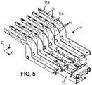
- the conveyor belt comprises a plurality of conveyor belts, synchronized, aligned with a predefined transverse pitch in the transverse direction perpendicular to the direction of movement of the conveyor belt, and spaced from each other in the transverse direction by transverse spacings of bands able to accommodate the longitudinal fingers of the robotic comb.
- the robotic reed comprises a frame on which the longitudinal fingers are mounted and a reed body integral with the displacement means, the frame and the reed body being fixed together by removable assembly means.
- the incoming batch support comprises a plurality of support pots of a cutting tool of a production line.
- the articles A can comprise at least a lower extension portion A1 and an upper portion A2 as is visible on the figure 8 , the upper portion A2 being arranged above the lower extension portion A1 in the vertical direction Z.
- the upper portion A2 has a greater transverse size than a transverse size of the lower extension portion A1.
- the lower die 27 comprises for example a plurality of openings distributed in the horizontal plane and forming cavities capable of receiving the pot supports 3 when the lower die 27 rises relative to the pot supports 3.
- the upper part 28 of the cutting tool 4 carries knives 28a which are arranged to come opposite grooves 27a made in the lower die at the desired cutting locations, so that the material of the articles A is sandwiched between the knives and grooves to be cut out.
- the upper part 28 may also include strippers 28b to facilitate the extraction of the articles A after cutting.
- one of the lower die 27, the upper part 28 and the pot supports 3 can for example be fixed, in particular the pot supports 3, while the others, in particular the lower die 27 and the upper part 28, can move along the vertical axis.
- the displacement of the conveyor belt 6 is carried out with a displacement speed V in the longitudinal direction X.
- displacement is meant that said at least one conveying belt 7 is driven in motion with a non-zero displacement speed V at least over part of an operating period of the conveying machine.
- speed of movement is thus meant a linear speed of said at least one conveyor belt 7 of the conveyor belt, for example in the frame of reference of the fixed frame 8 of the conveyor belt 6.
- the magnetic assembly means comprises a first element 24 mounted on the reed body 22 and a second element 25 mounted on the frame 21.
- the first element 24 and the second element 25 are such that a magnetic attraction force can exist between them when these elements are in proximity.
- the first element 24 can comprise a magnet while the second element 25 comprises a ferrite or vice versa.
- Said magnetic attraction force may in particular be sufficiently intense to secure the frame 21 to the reed body 22 in normal operation, that is to say when the forces exerted on the frame 21 and the reed body 22 are not top intense.
- the predefined magnetic attraction force can thus be calibrated by the choice of a permanent magnet for the first element 24 and/or the second element 25, and an adjustment of an air gap between the first element 24 and the second element 25, for example by means of peelable wedges.
- the longitudinal fingers 11 are regularly aligned so as to present a predefined transverse pitch Py identical to the transverse pitch of the articles A arranged on, or in, the incoming batch support 2.
- the longitudinal fingers 11 advantageously present, on at least one active portion of said longitudinal fingers 11, a transverse finger size Ed less than the transverse gripping spacings Ey separating the longitudinal columns C so as to be able to be introduced between the longitudinal columns C without touching the articles A of the said longitudinal columns C.
- the robotic comb 10 is moreover arranged in such a way that two neighboring longitudinal fingers 11 are able to transversely surround the articles A of a longitudinal column C and to support the articles A of the said longitudinal column in order to grasp them and bring them vertically. conveyor belt 6.
- the longitudinal grooves 12 are deep enough to accommodate the longitudinal fingers 11 of the robotic comb 10, when the articles A of the incoming batch L are placed on, or in, the incoming batch support 2, without said longitudinal fingers 11 entering in contact with the articles A of the incoming batch L.
- the incoming batch support 2 comprises a plurality of pot supports 3
- the grooves are formed in particular by the spaces separating the pot supports.
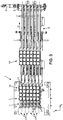
- Such a first routing section P1-P2 of the robotic comb 10 thus belongs to an inactive routing section of the robotic comb 10, illustrated in dotted lines on the figures 12 to 14 , that is to say a section of path on which the robotic comb does not perform any function of carrying the articles A.
- the moving means 13 raise the robotic reed 10 vertically, relative to the incoming batch support 2 horizontal, keeping the robotic reed 10 horizontal, so as to come contact, and lift from incoming lot 2 rack, items A of incoming lot L.
- moving the articles in the vertical direction simultaneously it is meant that all the articles A of the incoming batch are moved simultaneously, that is to say with a relative speed of the articles with respect to each other zero.
- the means of movement 13 may comprise means 14 capable of moving the robotic reed 10 in the vertical direction Z with the fingers 11 of the horizontal comb.
- These means 14 comprise for example an eccentric assembly controlled by a motor.
- the incoming batch support 2 is lowered vertically, relative to the horizontal robotic comb 10, on or in which the articles A are arranged, while maintaining said incoming batch support 2 horizontal, so as to come rest the articles A of the incoming batch L on the robotic comb 10 and in particular on the longitudinal fingers 11 of the robotic comb 10.
- the articles A are contacted only from below, in the vertical direction Z. More precisely, it is possible in particular to come and contact by below the upper portion A2 of the articles A by transversely surrounding the lower portion A1.
- the moving means 13 of the robotic reed 10 move the robotic reed 10 on a third path section P3-P4, to bring the articles A vertically to the conveyor belt 6 as illustrated in the figure 9 .
- the longitudinal fingers 11 of the robotic comb 10 each have an upper face 11a provided with a plurality of structures 11b, for example notches or extra thickness structures.
- the structures 11b are for example distributed along the longitudinal direction X of the longitudinal fingers 11 and able to wedge in the horizontal plane H the articles A seized during the movement of the robotic comb 10 in the horizontal plane H.
- the means of movement 13 of the robotic comb 10 can for example position the robotic comb 10 so that the upstream end of the robotic comb 10 is placed above the evacuation hole 17, if necessary close from the downstream end of the evacuation hole 17. Then, the means for evacuating defective articles detected 19 can sweep the articles A placed on the robotic comb 10 to cause them to fall into the evacuation hole 17.
- the adjustment and synchronization means 20 can also be connected to the drive motor 9 of the conveyor belt 6, or to a displacement speed sensor of the conveyor belt 6, so as to allow fine adjustment of the speed of movement of the articles A seized, that is to say the speed of movement of the robotic comb 10, with the speed of movement of the conveyor belt 6.
- the means of movement 13 of the robotic comb 10 are then implemented to move the articles A in the vertical direction Z , simultaneously, to bring the articles A to rest on the conveyor belt 6.
- the robotic comb 10 is moved over a fifth path section P5-P6 belonging to an active path section.
- the robotic comb 10 is lowered vertically in the vertical direction Z, relative to the fixed conveyor belt 6, by the means 14 capable of moving the robotic comb 10 in the vertical direction Z, while maintaining the horizontal movement of the articles A synchronized with the speed of movement V of the conveyor belt 6 thanks to the means 15 controlling the robotic comb 10 in the longitudinal direction X.
- the sixth path section thus belongs to an inactive path section of the robotic comb 10, illustrated in dotted lines on the figures 12 to 14 , that is to say a section of path on which the robotic comb does not perform any function of carrying the articles A.
Landscapes
- Engineering & Computer Science (AREA)
- Mechanical Engineering (AREA)
- Specific Conveyance Elements (AREA)
- Attitude Control For Articles On Conveyors (AREA)
Claims (16)
- Verfahren zum Fördern von Artikeln (A) in einer Produktionslinie, wobei- eine eingehende Gruppe (L) von Artikeln (A), die eine Mehrzahl von separaten Artikeln (A) umfasst, bereitgestellt wird und auf oder in einem Träger der eingehenden Gruppe (2) so angeordnet wird, dass sie in einer horizontalen Ebene (H) in einer oder mehreren Längssäulen (C) und/oder einer oder mehreren Querreihen ausgerichtet wird,- die Mehrzahl von Artikeln (A) der eingehenden Gruppe (L) gleichzeitig relativ zu dem Träger der eingehenden Gruppe (2) in einer vertikalen Richtung (Z) orthogonal zu der horizontalen Ebene (H) bewegt werden, wobei die Artikel (A) relativ zu dem Träger der eingehenden Gruppe (2) in der horizontalen Ebene (H) stationär bleiben so dass die Artikel (A) nicht mehr in Kontakt mit dem Träger der eingehenden Gruppe (2) sind und frei in der horizontalen Ebene (H) bewegt werden können, ohne den Träger der eingehenden Gruppe (2) zu berühren,- die erfassten Artikel (A) vertikal zu einem horizontalen Förderband (6) gebracht werden, wobei die Artikel (A) vertikal um einen vordefinierten vertikalen Abstand (E) zu dem Förderband (6) beabstandet sind,- die Artikel (A) dann gleichzeitig in vertikaler Richtung (Z) bewegt werden, um die Artikel (A) auf dem Förderband (6) abzulegen,- die Artikel (A) in einer Gruppe von ausgehenden Artikeln (S) über das Förderband (6) ausgegeben werden,dadurch gekennzeichnet, dass:- wenn die Artikel (A) vertikal auf das Förderband (6) zugeführt werden, das Förderband (6) in einer Bewegungsrichtung (D) der horizontalen Ebene (H) eine Bewegung mit einer Bewegungsgeschwindigkeit (V) aufweist,- sich die erfassten Artikel (A) orthogonal zum Förderband (6) befinden, eine horizontale Verschiebung der Artikel (A) gesteuert und mit der Bewegungsgeschwindigkeit (V) des Förderbandes (6) synchronisiert wird, und- die Artikel (A) in vertikaler Richtung (Z) bewegt werden, um die Artikel (A) auf dem Förderband (6) abzulegen, wobei die mit der Bewegungsgeschwindigkeit (V) des Förderbandes (6) synchronisierte horizontale Bewegung der Artikel (A) beibehalten wird.
- Verfahren nach Anspruch 1, dadurch gekennzeichnet, dass die Artikel (A) der eingehenden Gruppe (L) auf oder in dem Träger der eingehenden Gruppe (2) in Längssäulen (C) angeordnet werden, die regelmäßig so ausgerichtet werden, dass sie einen vordefinierten Querabstand (Py) entlang einer Querrichtung (Y) der horizontalen Ebene (H) aufweisen und entlang der Querrichtung (Y) durch Querabstände zum Greifen (Ey) zueinander beabstandet sind.
- Verfahren nach Anspruch 2, dadurch gekennzeichnet, dass zum gleichzeitigen Bewegen der Mehrzahl von Artikeln (A) der eingehenden Gruppe (L) entlang der vertikalen Richtung (Z) Längsfinger (11) eines Roboterkamms (10) in die Querabstände zum Erfassen (Ey) der eingehenden Gruppe (L) eingeführt werden, wobei die Längsfinger (11) regelmäßig derart ausgerichtet werden, dass sie den vordefinierten Querabstand (Py) aufweisen, und derart angeordnet werden, dass zwei benachbarte Längsfinger (11) in der Lage sind, die Artikel (A) einer Längssäule (C) von Artikeln der eingehenden Gruppe (L) quer zu umschließen und die Artikel (A) der besagten Längssäule (C) zu halten, um sie zu erfassen und in die Vertikale des Förderbandes (6) zu bringen und/oder der Roboterkamm (10) nur in der vertikalen Richtung (Z) und in einer horizontalen Richtung (X) bewegt wird, wobei die horizontale Richtung (X) insbesondere die Bewegungsrichtung (D) des Förderbandes (6) ist, und/oder der Roboterkamm (10) bewegt wird,- auf einem aktiven Wegabschnitt zum Zuführen der Artikel (A) in die Vertikale des Förderbands (6) mit einer ersten Bewegungsgeschwindigkeit (V1) in der horizontalen Ebene (H), und- auf einem inaktiven Rückwegabschnitt, wobei der Roboterkamm (10) keine Funktion zum Tragen der Artikel (A) ausführt, mit einer zweiten Bewegungsgeschwindigkeit (V2) in der horizontalen Ebene (H), die größer ist als die erste Bewegungsgeschwindigkeit (V1).
- Verfahren nach einem der Ansprüche 1 bis 3, dadurch gekennzeichnet, dass die Artikel (A) nur von unten, entlang einer vertikalen Richtung (Z), kontaktiert werden, insbesondere wobei die Artikel (A) wenigstens einen inneren Verlängerungsabschnitt (A1) und einen oberen Abschnitt (A2) umfassen, wobei der obere Abschnitt (A2) eine größere Querbeladung als die Querbeladung des inneren Verlängerungsabschnitts (A1) aufweist, und wobei, um die Artikel (A) des eingehenden Gruppes (L) in einer vertikalen Richtung (Z) zu bewegen, der obere Abschnitt (A2) von unten kontaktiert wird, indem der untere Abschnitt (A1) quer umschlossen wird,
wobei insbesondere die Artikel (A) von einem Typ sind, der einen Körper mit einer Bodenwand, einer in sich geschlossenen Seitenwand und einem Verschluss von oben sowie einen Flansch zum Verschluss von oben hin umfasst, wobei der Körper den unteren Verlängerungsabschnitt (A1) bildet und der Flansch den oberen Abschnitt (A2) bildet. - Verfahren nach einem der Ansprüche 1 bis 4, dadurch gekennzeichnet, dass zum Bewegen der Artikel (A) der eingehenden Gruppe (L) in einer vertikalen Richtung (Z) ein Roboterkamm (10) in Bezug auf den horizontalen Träger der eingehenden Gruppe (2) vertikal angebracht wird, wobei der Roboterkamm (10) horizontal gehalten wird, um die Artikel (A) der eingehenden Gruppe (2) zu kontaktieren und diese vom Träger der eingehenden Gruppe (2) abzuheben, und/oder der Träger der eingehenden Gruppe (2), auf oder in welchem die Artikel (A) angeordnet sind, in Bezug auf einen horizontalen Roboterkamm (10) abgesenkt wird, wobei der Roboterkamm (10) horizontal gehalten wird, so dass die Artikel (A) der eingehenden Gruppe (L) auf dem Roboterkamm (10) abgelegt werden,
wobei insbesondere ein Roboterkamm (10) und/oder der Träger der eingehenden Gruppe (2) so bewegt werden, dass der Roboterkamm (10) und der Träger der eingehenden Gruppe (2) bei einem Kontakt zwischen dem Roboterkamm (10) und den Artikeln (A) der eingehenden Gruppe (L) eine vertikale Relativgeschwindigkeit von weniger als 200 Millimetern pro Sekunde aufweisen. - Verfahren nach einem der Ansprüche 1 bis 5, dadurch gekennzeichnet, dass zum Bewegen der Artikel (A) in vertikaler Richtung (Z), um die Artikel (A) auf dem Förderband (6) abzulegen, ein Roboterkamm (10) vertikal in Bezug auf das feste Förderband (6) abgesenkt wird, um die Artikel (A) auf dem Förderband (6) abzulegen,
wobei insbesondere, um die Artikel (A) auf dem Förderband (6) abzulegen, der Roboterkamm (10) vertikal in Bezug auf das Förderband (6) über einen vertikalen Hub abgesenkt wird, der größer als der vordefinierte vertikale Abstand (E) ist, so dass die Artikel (A) am Ende des vertikalen Hubs den Kontakt mit dem Roboterkamm (10) verlieren. - Verfahren nach einem der Ansprüche 1 bis 6, dadurch gekennzeichnet, dass zum Ausgeben der Artikel (A) in einer Gruppe von ausgehenden Artikeln (S) mittels des Förderbandes (6) die Artikel (A) auf dem Förderband (6) in Bewegungsrichtung (D) der horizontalen Ebene (H) geführt werden, insbesondere mittels Längsfingern (11) eines die Artikel (A) quer umschließenden Roboterkamms (10).
- Verfahren nach einem der Ansprüche 1 bis 7, dadurch gekennzeichnet, dass, während die erfassten Artikel (A) in die Vertikale des Förderbandes (6) gebracht werden, wenigstens ein physikalisches Merkmal der erfassten Artikel (A) gemessen wird, insbesondere:- aus dem gemessenen physikalischen Merkmal das Vorhandensein oder Nichtvorhandensein von fehlerhaften Artikeln unter den erfassten Artikeln (A) bestimmt wird, und- wenn festgestellt wird, dass sich unter den erfassten Artikeln (A) fehlerhafte Artikel befinden, die erfassten Artikel (A) entfernt werden, und/odervon den Artikeln (A) Artikelschnittabfälle vertikal entfernt werden, so dass die Artikelschnittabfälle nicht mit den erfassten Artikeln (A) in Kontakt kommen.
- Verfahren nach einem der Ansprüche 1 bis 8, dadurch gekennzeichnet, dass die Artikel (A) der Gruppe von ausgehenden Artikeln (S) in der horizontalen Ebene (H) die gleichen relativen Ausrichtungen und die gleichen relativen Positionen wie die Artikel der eingehenden Gruppe (L) aufweisen, und/oder,
wenn eine horizontale Bewegung der Artikel (A) gesteuert und mit der Bewegungsgeschwindigkeit (V) des Förderbandes (6) synchronisiert wird, eine horizontale Position der Artikel (A) der Gruppe von ausgehenden Artikeln (S) relativ zum Förderband (6), insbesondere eine horizontale Position in der Bewegungsrichtung (D) des Förderbandes, definiert wird. - Maschine zum Fördern von Artikeln (A) in einer Produktionslinie, zur Durchführung des Verfahrens nach einem der Ansprüche 1 bis 9, umfassend:- stromaufwärts einen Träger der eingehenden Gruppe (2), auf oder in dem eine Mehrzahl von Artikeln (A), die von einer eingehenden Gruppe (L) von Artikeln (A) getrennt wurden, derart angeordnet sind, dass sie in einer horizontalen Ebene (H) in einer oder mehreren Längssäulen (C) und/oder einer oder mehreren Querreihen ausgerichtet sind,- stromabwärts ein horizontales Förderband (6) zum Ausgeben der Artikel (A) in einer Gruppe von ausgehenden Artikeln (S),- stromaufwärts Mittel (10, 13) zum gleichzeitigen Bewegen der Mehrzahl von Artikeln (A) der eingehenden Gruppe (L) in einer vertikalen Richtung (Z) orthogonal zur horizontalen Ebene (H), wobei die Artikel (A) in Bezug auf den Träger der eingehenden Gruppe (2) in der horizontalen Ebene (H) stationär gehalten werden, so dass die Artikel (A) nicht mehr mit dem Träger der eingehenden Gruppe (2) in Kontakt kommen und in der horizontalen Ebene (H) frei bewegt werden können, ohne den Träger der eingehenden Gruppe (2) zu kontaktieren,- stromabwärts Mittel (10, 13), um die erfassten Artikel (A) in die Vertikale des Förderbands (6) zu bringen, wobei die Artikel (A) vertikal um einen vordefinierten vertikalen Abstand (E) zum Förderband (6) beabstandet sind,- stromabwärts Mittel (10, 13) zum gleichzeitigen Bewegen der Artikel (A) in vertikaler Richtung (Z), um die Artikel (A) auf dem Förderband (6) abzulegen,dadurch gekennzeichnet, dass- das Förderband (6) eine Bewegung in einer Bewegungsrichtung (D) der horizontalen Ebene (H) mit einer Bewegungsgeschwindigkeit (V) aufweist, wenigstens dann, wenn die Artikel (A) dem Förderband (6) vertikal zugeführt werden,- die Maschine ferner stromabwärts Mittel zum Einstellen und Synchronisieren (20) einer horizontalen Verschiebung der in die Vertikale des Förderbandes (6) gebrachten Artikel (A) mit der Bewegungsgeschwindigkeit (V) des Förderbandes umfasst, und- die Mittel (10, 13) zum Bewegen der Artikel (A) in der vertikalen Richtung (Z), um die Artikel (A) auf dem Förderband (6) abzulegen, dazu ausgebildet sind, die Artikel (A) in der vertikalen Richtung (Z) zu bewegen, wobei die mit der Bewegungsgeschwindigkeit (V) des Förderbandes (6) synchronisierte horizontale Bewegung der Artikel (A) beibehalten wird.
- Maschine nach Anspruch 10, dadurch gekennzeichnet, dass die Mittel (10, 13), um die erfassten Artikel (A) in die Vertikale des Förderbandes (6) zu bringen, einen Roboterkamm (10) und Mittel zum Bewegen (13) des Roboterkamms (10) umfassen,wobei insbesondere der Roboterkamm (10) mit Längsfingern (11) versehen ist, die regelmäßig ausgerichtet sind, so dass sie einen vordefinierten Querabstand (Py) entlang einer Querrichtung (Y) der horizontalen Ebene (H) orthogonal zur Bewegungsrichtung (D) des Förderbandes (6) aufweisen und derart angeordnet sind, dass zwei benachbarte Längsfinger (11) in der Lage sind, die Artikel (A) einer Längssäule (C) von Artikeln der eingehenden Gruppe (L) quer zu umschließen und die Artikel (A) der Längssäule (C) zu halten, um sie zu erfassen und sie in die Vertikale des Förderbandes zu bringen,wobei insbesondere die Längsfinger (11) des Roboterkamms (10) jeweils eine Oberseite (11a) aufweisen, die mit einer Mehrzahl von Strukturen (11b) versehen ist, die entlang der horizontalen Richtung (X) der Längsfinger (11) verteilt sind, wobei insbesondere der Roboterkamm (10) einen Rahmen (21) umfasst, auf welchem die Längsfinger (11) montiert sind, und einen Kammkörper (22) umfasst, der fest mit den Bewegungsmitteln (13) verbunden ist, wobei der Rahmen (21) und der Kammkörper (22) durch entfernbare Verbindungsmittel (23) aneinander befestigt sind, insbesondere wobei die entfernbaren Verbindungsmittel (23) magnetische Verbindungsmittel sind, umfassend ein erstes Element (24), das an dem Kammkörper (22) angebracht ist, und ein zweites Element (25), das an dem Rahmen (21) angebracht ist, wobei die entfernbaren Verbindungsmittel (23) dazu ausgebildet sind, den Rahmen (21) an dem Kammkörper (22) in Reaktion auf eine Last, die ausreichend groß ist, um eine vordefinierte magnetische Anziehungskraft zwischen dem ersten Element (24) und dem zweiten Element (25) zu überwinden, entfernbar zu befestigen.
- Maschine nach Anspruch 11, dadurch gekennzeichnet, dass der Träger der eingehenden Gruppe (2) eine Mehrzahl von Längsnuten (12) aufweist, die mit einem vordefinierten Querabstand (Py) entlang einer Querrichtung (Y) der horizontalen Ebene (H) orthogonal zur Bewegungsrichtung (D) des Förderbandes (6) regelmäßig ausgerichtet sind, wobei die Längsnuten (12) dazu ausgebildet sind, die Längsfinger (11) des Roboterkamms (10) aufzunehmen.
- Maschine nach einem der Ansprüche 11 und 12, dadurch gekennzeichnet, dass das Förderband (6) eine Mehrzahl von synchronisierten Förderbändern (7) umfasst, die mit einem vordefinierten Querabstand (Py) entlang der Querrichtung (Y) orthogonal zur Bewegungsrichtung (D) des Förderbandes (6) ausgerichtet sind und in Querrichtung (Y) durch transversale Bandabstände (Eb) zueinander beabstandet sind, die zur Aufnahme der Längsfinger (11) des Roboterkamms (10) ausgebildet sind.
- Maschine nach einem der Ansprüche 11 bis 13, dadurch gekennzeichnet, dass die Bewegungsmittel (13),Mittel (15) zur Bewegung des Roboterkamms (10) in einer horizontalen Richtung (X) umfassen, die von den Mitteln zum Einstellen und Synchronisieren (20) mit der Bewegungsgeschwindigkeit (V) des Förderbandes (6) gesteuert werden,wobei die Mittel (15) insbesondere einen Linearmotor (14), beispielsweise in Form eines magnetischen Zylinders, umfassen und/oderMittel (14) zum Bewegen des Roboterkamms (10) in vertikaler Richtung (Z), die dazu ausgebildet sind, den Roboterkamm (10) zu bewegen, während die Längsfinger (11) des Roboterkamms (10) horizontal beibehalten werden, wobei die Mittel (14) insbesondere eine Exzenter-Einheit umfassen.
- Maschine nach einem der Ansprüche 10 bis 14, dadurch gekennzeichnet, dass sie ferner Mittel zum Messen (16) wenigstens eines physikalischen Merkmals der erfassten Artikel (A) umfasst, insbesondere dadurch, dass sie ferner Bestimmungsmittel (18) umfasst, die dazu ausgebildet sind, das Vorhandensein oder Nichtvorhandensein von fehlerhaften Artikeln unter den erfassten Artikeln (A) auf der Grundlage des besagten physikalischen Merkmals der erfassten Artikel (A) zu bestimmen, sowie Mittel zum Entfernen (19) von als fehlerhaft erkannten Artikeln, insbesondere derart, dass die Mittel zum Entfernen (19) von als fehlerhaft erkannten Artikeln ein Entnahmeloch (17) umfassen, welches das Förderband (6) von dem Träger der eingehenden Gruppe (2) in der horizontalen Ebene (H) trennt, wobei die Mittel zum Entfernen (19) von als fehlerhaft erkannten Artikeln dazu ausgebildet sind, die fehlerhaften Artikel durch das Entnahmeloch (17) von den erfassten Artikeln (A) zu entfernen.
- Maschine nach einem der Ansprüche 10 bis 15, dadurch gekennzeichnet, dass der Träger der eingehenden Gruppe (2) eine Mehrzahl von Topfhaltern (3) eines Schneidwerkzeugs (4) einer Produktionslinie umfasst, insbesondere wobei gegebenenfalls die Mehrzahl von Strukturen (11b) dazu ausgebildet sind, erfasste Artikel (A) von Artikelschnittabfällen (29) bei einer Bewegung des Roboterkamms vertikal zu entfernen.
Priority Applications (1)
| Application Number | Priority Date | Filing Date | Title |
|---|---|---|---|
| PL16156571T PL3059191T4 (pl) | 2015-02-20 | 2016-02-19 | Maszyna i sposób przenoszenia artykułów |
Applications Claiming Priority (1)
| Application Number | Priority Date | Filing Date | Title |
|---|---|---|---|
| FR1551481A FR3032950B1 (fr) | 2015-02-20 | 2015-02-20 | Machine et procede de convoyage d'articles |
Publications (2)
| Publication Number | Publication Date |
|---|---|
| EP3059191A1 EP3059191A1 (de) | 2016-08-24 |
| EP3059191B1 true EP3059191B1 (de) | 2022-01-12 |
Family
ID=53059277
Family Applications (1)
| Application Number | Title | Priority Date | Filing Date |
|---|---|---|---|
| EP16156571.8A Active EP3059191B1 (de) | 2015-02-20 | 2016-02-19 | Maschine und verfahren zur förderung von artikeln |
Country Status (7)
| Country | Link |
|---|---|
| US (1) | US9764907B2 (de) |
| EP (1) | EP3059191B1 (de) |
| JP (1) | JP6715615B2 (de) |
| CN (1) | CN105905520B (de) |
| ES (1) | ES2911237T3 (de) |
| FR (1) | FR3032950B1 (de) |
| PL (1) | PL3059191T4 (de) |
Families Citing this family (9)
| Publication number | Priority date | Publication date | Assignee | Title |
|---|---|---|---|---|
| CN107176448A (zh) * | 2017-07-10 | 2017-09-19 | 中国大冢制药有限公司 | 安瓿制品自动分离系统 |
| FR3075769B1 (fr) * | 2017-12-27 | 2021-12-17 | Gebo Packaging Solutions France | Transfert de produits entre une zone de transit et une surface d'accumulation |
| CN109231123A (zh) * | 2018-10-30 | 2019-01-18 | 四川击瓦云智能科技有限公司 | 一种多通道瓶体输送装置 |
| CN113012346A (zh) * | 2021-04-09 | 2021-06-22 | 苏州优智达机器人有限公司 | 物品取放构件、组件、方法及系统 |
| JP7767769B2 (ja) * | 2021-08-20 | 2025-11-12 | オムロン株式会社 | 搬送システム |
| WO2023137524A1 (en) * | 2022-01-20 | 2023-07-27 | Matthew Ian Angilley | Automated punnets handling assembly |
| CN115397126B (zh) * | 2022-08-23 | 2025-06-27 | 深圳市高新投三江电子股份有限公司 | 一种通用pcb板浸蜡装置 |
| CN120534695B (zh) * | 2025-06-16 | 2026-01-27 | 徐州淳康生物科技有限公司 | 一种食品生产用智能悬挂输送系统 |
| CN121516495B (zh) * | 2026-01-16 | 2026-04-07 | 包头盛泰汽车零部件制造有限公司 | 一种用于轮毂加工的输送上线装置 |
Citations (1)
| Publication number | Priority date | Publication date | Assignee | Title |
|---|---|---|---|---|
| EP2668124A1 (de) * | 2011-01-25 | 2013-12-04 | CARLE & MONTANARI - OPM S.p.A. | Ringförderer |
Family Cites Families (11)
| Publication number | Priority date | Publication date | Assignee | Title |
|---|---|---|---|---|
| US4191003A (en) * | 1978-04-19 | 1980-03-04 | Talarico Lawrence J | Tray loader |
| US4457121A (en) * | 1982-09-27 | 1984-07-03 | Standard-Knapp, Inc. | Continuous motion bottle packer |
| CA1267716A (en) | 1984-02-23 | 1990-04-10 | Frederick W. Scholl | Edge-emitting light emitting diode |
| IT1219312B (it) * | 1988-05-18 | 1990-05-03 | Cavanna Spa | Procedimento e relativo impianto per il trattamento di articoli particolarmente per linee di confezionamento automatico |
| FR2673611B1 (fr) | 1991-03-05 | 1995-09-01 | Merlin Gerin | Dispositif rapide d'amenage et de positionnement a cinematique rectangulaire allongee. |
| JPH06234418A (ja) * | 1993-02-08 | 1994-08-23 | Shibuya Kogyo Co Ltd | 整列機構を備えた物品取出し装置 |
| IT1304279B1 (it) * | 1998-04-21 | 2001-03-13 | Zecchetti Srl | Dispositivo per alimentare strati di oggetti ad un impianto dipalettizzazione. |
| FR2792920B1 (fr) * | 1999-04-27 | 2001-06-15 | Loire Etudes Realisations Meca | Installation et procede de convoyage de produits selon deux directions |
| IT1318125B1 (it) * | 2000-07-05 | 2003-07-23 | Vortex Systems Srl | Apparecchiatura di alimentazione di gruppi di prodotti ad untrasportatore per il loro imballaggio. |
| DE10127896B4 (de) * | 2001-06-08 | 2005-02-24 | Indag Gesellschaft für Industriebedarf mbH & Co. Betriebs KG | Übergabevorrichtung und -verfahren für Folienbeutel |
| WO2007038311A1 (en) * | 2005-09-23 | 2007-04-05 | Delkor Systems, Inc. | Split package assembly |
-
2015
- 2015-02-20 FR FR1551481A patent/FR3032950B1/fr active Active
-
2016
- 2016-02-12 US US15/042,337 patent/US9764907B2/en active Active
- 2016-02-19 EP EP16156571.8A patent/EP3059191B1/de active Active
- 2016-02-19 PL PL16156571T patent/PL3059191T4/pl unknown
- 2016-02-19 JP JP2016029705A patent/JP6715615B2/ja not_active Expired - Fee Related
- 2016-02-19 CN CN201610092760.9A patent/CN105905520B/zh active Active
- 2016-02-19 ES ES16156571T patent/ES2911237T3/es active Active
Patent Citations (1)
| Publication number | Priority date | Publication date | Assignee | Title |
|---|---|---|---|---|
| EP2668124A1 (de) * | 2011-01-25 | 2013-12-04 | CARLE & MONTANARI - OPM S.p.A. | Ringförderer |
Also Published As
| Publication number | Publication date |
|---|---|
| FR3032950A1 (fr) | 2016-08-26 |
| FR3032950B1 (fr) | 2017-03-17 |
| JP2016179858A (ja) | 2016-10-13 |
| PL3059191T3 (pl) | 2022-07-11 |
| US20160244272A1 (en) | 2016-08-25 |
| PL3059191T4 (pl) | 2022-07-11 |
| JP6715615B2 (ja) | 2020-07-01 |
| EP3059191A1 (de) | 2016-08-24 |
| CN105905520A (zh) | 2016-08-31 |
| US9764907B2 (en) | 2017-09-19 |
| CN105905520B (zh) | 2020-08-04 |
| ES2911237T3 (es) | 2022-05-18 |
Similar Documents
| Publication | Publication Date | Title |
|---|---|---|
| EP3059191B1 (de) | Maschine und verfahren zur förderung von artikeln | |
| EP2341001B1 (de) | Verfahren und Maschine zur Umverpackung von Artikeln zur Bildung von Artikellosen, bestehend aus einer Vielzahl von Artikeln und einer Umverpackung aus Karton | |
| EP3802377B1 (de) | Überführen von produkten durch einfassing aus oder zu einem speicherbereich | |
| EP2648978B1 (de) | Einpackverfahren und vorrichtung zum sequenziellen einpacken von produktchargen in verpackungsbehältern | |
| WO2019129968A1 (fr) | Déplacement de produits sur une zone de transit | |
| EP3595991A1 (de) | Herstellung von chargen von produkten zum palettisieren in schichten | |
| WO2013001203A1 (fr) | Procede et machine d'encaissage de produits, avec intercalaire(s) | |
| EP2978697B1 (de) | Verfahren und system zum transportieren von objekten | |
| EP2551222A1 (de) | Anlage zur Beförderung von Produkten, insbesondere von Lebensmitteltranchen | |
| FR2998284A1 (fr) | Dispositif et procede de placement d'une decoupe pour boites d'emballages avec depilage vertical et tapis de transfert. | |
| WO2019243674A1 (fr) | Appareil et procédé de transfert, vers une ligne de traitement, d'imprimés initialement conditionnés en liasse | |
| EP3256409A1 (de) | Verfahren und system zum entladen einer verpackung | |
| FR3049933A1 (fr) | Systeme et procede de manipulation d'articles tels que recipients a boisson ou similaire | |
| EP3562771B1 (de) | Robotisierte palettierung | |
| EP3856665A1 (de) | Vorrichtung und verfahren zum transfer von produkten | |
| EP3511135B1 (de) | Schneideanlage von lebensmittelprodukten, die mit mitteln zum füllen einer rinne ausgestattet ist | |
| FR3060547A1 (fr) | Appareil et procede de transfert, vers une ligne de traitement, d'imprimes initialement conditionnes en liasse | |
| FR3074487A1 (fr) | Realisation de lots de produits en vue d'une palettisation par couches | |
| FR3060538A1 (fr) | Procede et appareil pour sectionner un lien entourant une liasse d'imprimes provenant d'une palette | |
| WO2012110723A1 (fr) | Outil de manipulation de produits | |
| EP3075686B1 (de) | Vorrichtung und verfahren zur rotation von artikeln | |
| FR3088315A1 (fr) | Dispositif de convoyage de produits et procede de gestion du transfert desdits produits | |
| FR2998272A1 (fr) | Installation et procede d'emballage de fruits ou legumes | |
| EP1792857A1 (de) | Verfahren zum Fördern und Speichern von Artikeln in einer Puffereinrichtung, und Einrichtung um dieses Verfahren auszuführen | |
| FR3046999A1 (fr) | Dispositif et methode de transfert de produits |
Legal Events
| Date | Code | Title | Description |
|---|---|---|---|
| PUAI | Public reference made under article 153(3) epc to a published international application that has entered the european phase |
Free format text: ORIGINAL CODE: 0009012 |
|
| AK | Designated contracting states |
Kind code of ref document: A1 Designated state(s): AL AT BE BG CH CY CZ DE DK EE ES FI FR GB GR HR HU IE IS IT LI LT LU LV MC MK MT NL NO PL PT RO RS SE SI SK SM TR |
|
| AX | Request for extension of the european patent |
Extension state: BA ME |
|
| STAA | Information on the status of an ep patent application or granted ep patent |
Free format text: STATUS: REQUEST FOR EXAMINATION WAS MADE |
|
| 17P | Request for examination filed |
Effective date: 20170221 |
|
| RBV | Designated contracting states (corrected) |
Designated state(s): AL AT BE BG CH CY CZ DE DK EE ES FI FR GB GR HR HU IE IS IT LI LT LU LV MC MK MT NL NO PL PT RO RS SE SI SK SM TR |
|
| RAP1 | Party data changed (applicant data changed or rights of an application transferred) |
Owner name: SYNERLINK |
|
| GRAP | Despatch of communication of intention to grant a patent |
Free format text: ORIGINAL CODE: EPIDOSNIGR1 |
|
| STAA | Information on the status of an ep patent application or granted ep patent |
Free format text: STATUS: GRANT OF PATENT IS INTENDED |
|
| INTG | Intention to grant announced |
Effective date: 20210805 |
|
| GRAS | Grant fee paid |
Free format text: ORIGINAL CODE: EPIDOSNIGR3 |
|
| GRAA | (expected) grant |
Free format text: ORIGINAL CODE: 0009210 |
|
| STAA | Information on the status of an ep patent application or granted ep patent |
Free format text: STATUS: THE PATENT HAS BEEN GRANTED |
|
| AK | Designated contracting states |
Kind code of ref document: B1 Designated state(s): AL AT BE BG CH CY CZ DE DK EE ES FI FR GB GR HR HU IE IS IT LI LT LU LV MC MK MT NL NO PL PT RO RS SE SI SK SM TR |
|
| REG | Reference to a national code |
Ref country code: GB Ref legal event code: FG4D Free format text: NOT ENGLISH |
|
| REG | Reference to a national code |
Ref country code: CH Ref legal event code: EP |
|
| REG | Reference to a national code |
Ref country code: IE Ref legal event code: FG4D Free format text: LANGUAGE OF EP DOCUMENT: FRENCH |
|
| REG | Reference to a national code |
Ref country code: DE Ref legal event code: R096 Ref document number: 602016068253 Country of ref document: DE |
|
| REG | Reference to a national code |
Ref country code: AT Ref legal event code: REF Ref document number: 1462246 Country of ref document: AT Kind code of ref document: T Effective date: 20220215 |
|
| REG | Reference to a national code |
Ref country code: LT Ref legal event code: MG9D |
|
| REG | Reference to a national code |
Ref country code: NL Ref legal event code: MP Effective date: 20220112 Ref country code: ES Ref legal event code: FG2A Ref document number: 2911237 Country of ref document: ES Kind code of ref document: T3 Effective date: 20220518 |
|
| REG | Reference to a national code |
Ref country code: AT Ref legal event code: MK05 Ref document number: 1462246 Country of ref document: AT Kind code of ref document: T Effective date: 20220112 |
|
| PG25 | Lapsed in a contracting state [announced via postgrant information from national office to epo] |
Ref country code: NL Free format text: LAPSE BECAUSE OF FAILURE TO SUBMIT A TRANSLATION OF THE DESCRIPTION OR TO PAY THE FEE WITHIN THE PRESCRIBED TIME-LIMIT Effective date: 20220112 |
|
| PG25 | Lapsed in a contracting state [announced via postgrant information from national office to epo] |
Ref country code: SE Free format text: LAPSE BECAUSE OF FAILURE TO SUBMIT A TRANSLATION OF THE DESCRIPTION OR TO PAY THE FEE WITHIN THE PRESCRIBED TIME-LIMIT Effective date: 20220112 Ref country code: RS Free format text: LAPSE BECAUSE OF FAILURE TO SUBMIT A TRANSLATION OF THE DESCRIPTION OR TO PAY THE FEE WITHIN THE PRESCRIBED TIME-LIMIT Effective date: 20220112 Ref country code: PT Free format text: LAPSE BECAUSE OF FAILURE TO SUBMIT A TRANSLATION OF THE DESCRIPTION OR TO PAY THE FEE WITHIN THE PRESCRIBED TIME-LIMIT Effective date: 20220512 Ref country code: NO Free format text: LAPSE BECAUSE OF FAILURE TO SUBMIT A TRANSLATION OF THE DESCRIPTION OR TO PAY THE FEE WITHIN THE PRESCRIBED TIME-LIMIT Effective date: 20220412 Ref country code: LT Free format text: LAPSE BECAUSE OF FAILURE TO SUBMIT A TRANSLATION OF THE DESCRIPTION OR TO PAY THE FEE WITHIN THE PRESCRIBED TIME-LIMIT Effective date: 20220112 Ref country code: HR Free format text: LAPSE BECAUSE OF FAILURE TO SUBMIT A TRANSLATION OF THE DESCRIPTION OR TO PAY THE FEE WITHIN THE PRESCRIBED TIME-LIMIT Effective date: 20220112 Ref country code: BG Free format text: LAPSE BECAUSE OF FAILURE TO SUBMIT A TRANSLATION OF THE DESCRIPTION OR TO PAY THE FEE WITHIN THE PRESCRIBED TIME-LIMIT Effective date: 20220412 |
|
| PG25 | Lapsed in a contracting state [announced via postgrant information from national office to epo] |
Ref country code: LV Free format text: LAPSE BECAUSE OF FAILURE TO SUBMIT A TRANSLATION OF THE DESCRIPTION OR TO PAY THE FEE WITHIN THE PRESCRIBED TIME-LIMIT Effective date: 20220112 Ref country code: GR Free format text: LAPSE BECAUSE OF FAILURE TO SUBMIT A TRANSLATION OF THE DESCRIPTION OR TO PAY THE FEE WITHIN THE PRESCRIBED TIME-LIMIT Effective date: 20220413 Ref country code: FI Free format text: LAPSE BECAUSE OF FAILURE TO SUBMIT A TRANSLATION OF THE DESCRIPTION OR TO PAY THE FEE WITHIN THE PRESCRIBED TIME-LIMIT Effective date: 20220112 Ref country code: AT Free format text: LAPSE BECAUSE OF FAILURE TO SUBMIT A TRANSLATION OF THE DESCRIPTION OR TO PAY THE FEE WITHIN THE PRESCRIBED TIME-LIMIT Effective date: 20220112 |
|
| PG25 | Lapsed in a contracting state [announced via postgrant information from national office to epo] |
Ref country code: IS Free format text: LAPSE BECAUSE OF FAILURE TO SUBMIT A TRANSLATION OF THE DESCRIPTION OR TO PAY THE FEE WITHIN THE PRESCRIBED TIME-LIMIT Effective date: 20220512 |
|
| REG | Reference to a national code |
Ref country code: DE Ref legal event code: R097 Ref document number: 602016068253 Country of ref document: DE |
|
| REG | Reference to a national code |
Ref country code: CH Ref legal event code: PL |
|
| PG25 | Lapsed in a contracting state [announced via postgrant information from national office to epo] |
Ref country code: SM Free format text: LAPSE BECAUSE OF FAILURE TO SUBMIT A TRANSLATION OF THE DESCRIPTION OR TO PAY THE FEE WITHIN THE PRESCRIBED TIME-LIMIT Effective date: 20220112 Ref country code: SK Free format text: LAPSE BECAUSE OF FAILURE TO SUBMIT A TRANSLATION OF THE DESCRIPTION OR TO PAY THE FEE WITHIN THE PRESCRIBED TIME-LIMIT Effective date: 20220112 Ref country code: RO Free format text: LAPSE BECAUSE OF FAILURE TO SUBMIT A TRANSLATION OF THE DESCRIPTION OR TO PAY THE FEE WITHIN THE PRESCRIBED TIME-LIMIT Effective date: 20220112 Ref country code: MC Free format text: LAPSE BECAUSE OF FAILURE TO SUBMIT A TRANSLATION OF THE DESCRIPTION OR TO PAY THE FEE WITHIN THE PRESCRIBED TIME-LIMIT Effective date: 20220112 Ref country code: LU Free format text: LAPSE BECAUSE OF NON-PAYMENT OF DUE FEES Effective date: 20220219 Ref country code: EE Free format text: LAPSE BECAUSE OF FAILURE TO SUBMIT A TRANSLATION OF THE DESCRIPTION OR TO PAY THE FEE WITHIN THE PRESCRIBED TIME-LIMIT Effective date: 20220112 Ref country code: DK Free format text: LAPSE BECAUSE OF FAILURE TO SUBMIT A TRANSLATION OF THE DESCRIPTION OR TO PAY THE FEE WITHIN THE PRESCRIBED TIME-LIMIT Effective date: 20220112 Ref country code: CZ Free format text: LAPSE BECAUSE OF FAILURE TO SUBMIT A TRANSLATION OF THE DESCRIPTION OR TO PAY THE FEE WITHIN THE PRESCRIBED TIME-LIMIT Effective date: 20220112 |
|
| PLBE | No opposition filed within time limit |
Free format text: ORIGINAL CODE: 0009261 |
|
| STAA | Information on the status of an ep patent application or granted ep patent |
Free format text: STATUS: NO OPPOSITION FILED WITHIN TIME LIMIT |
|
| PG25 | Lapsed in a contracting state [announced via postgrant information from national office to epo] |
Ref country code: AL Free format text: LAPSE BECAUSE OF FAILURE TO SUBMIT A TRANSLATION OF THE DESCRIPTION OR TO PAY THE FEE WITHIN THE PRESCRIBED TIME-LIMIT Effective date: 20220112 |
|
| 26N | No opposition filed |
Effective date: 20221013 |
|
| PG25 | Lapsed in a contracting state [announced via postgrant information from national office to epo] |
Ref country code: LI Free format text: LAPSE BECAUSE OF NON-PAYMENT OF DUE FEES Effective date: 20220228 Ref country code: IE Free format text: LAPSE BECAUSE OF NON-PAYMENT OF DUE FEES Effective date: 20220219 Ref country code: CH Free format text: LAPSE BECAUSE OF NON-PAYMENT OF DUE FEES Effective date: 20220228 |
|
| PG25 | Lapsed in a contracting state [announced via postgrant information from national office to epo] |
Ref country code: SI Free format text: LAPSE BECAUSE OF FAILURE TO SUBMIT A TRANSLATION OF THE DESCRIPTION OR TO PAY THE FEE WITHIN THE PRESCRIBED TIME-LIMIT Effective date: 20220112 |
|
| PGFP | Annual fee paid to national office [announced via postgrant information from national office to epo] |
Ref country code: PL Payment date: 20230220 Year of fee payment: 8 Ref country code: GB Payment date: 20230324 Year of fee payment: 8 Ref country code: BE Payment date: 20230227 Year of fee payment: 8 |
|
| PG25 | Lapsed in a contracting state [announced via postgrant information from national office to epo] |
Ref country code: IT Free format text: LAPSE BECAUSE OF FAILURE TO SUBMIT A TRANSLATION OF THE DESCRIPTION OR TO PAY THE FEE WITHIN THE PRESCRIBED TIME-LIMIT Effective date: 20220112 |
|
| PG25 | Lapsed in a contracting state [announced via postgrant information from national office to epo] |
Ref country code: HU Free format text: LAPSE BECAUSE OF FAILURE TO SUBMIT A TRANSLATION OF THE DESCRIPTION OR TO PAY THE FEE WITHIN THE PRESCRIBED TIME-LIMIT; INVALID AB INITIO Effective date: 20160219 |
|
| PG25 | Lapsed in a contracting state [announced via postgrant information from national office to epo] |
Ref country code: MK Free format text: LAPSE BECAUSE OF FAILURE TO SUBMIT A TRANSLATION OF THE DESCRIPTION OR TO PAY THE FEE WITHIN THE PRESCRIBED TIME-LIMIT Effective date: 20220112 Ref country code: CY Free format text: LAPSE BECAUSE OF FAILURE TO SUBMIT A TRANSLATION OF THE DESCRIPTION OR TO PAY THE FEE WITHIN THE PRESCRIBED TIME-LIMIT Effective date: 20220112 |
|
| PG25 | Lapsed in a contracting state [announced via postgrant information from national office to epo] |
Ref country code: MT Free format text: LAPSE BECAUSE OF FAILURE TO SUBMIT A TRANSLATION OF THE DESCRIPTION OR TO PAY THE FEE WITHIN THE PRESCRIBED TIME-LIMIT Effective date: 20220112 |
|
| GBPC | Gb: european patent ceased through non-payment of renewal fee |
Effective date: 20240219 |
|
| REG | Reference to a national code |
Ref country code: BE Ref legal event code: MM Effective date: 20240229 |
|
| PG25 | Lapsed in a contracting state [announced via postgrant information from national office to epo] |
Ref country code: BE Free format text: LAPSE BECAUSE OF NON-PAYMENT OF DUE FEES Effective date: 20240229 |
|
| PG25 | Lapsed in a contracting state [announced via postgrant information from national office to epo] |
Ref country code: GB Free format text: LAPSE BECAUSE OF NON-PAYMENT OF DUE FEES Effective date: 20240219 |
|
| PG25 | Lapsed in a contracting state [announced via postgrant information from national office to epo] |
Ref country code: GB Free format text: LAPSE BECAUSE OF NON-PAYMENT OF DUE FEES Effective date: 20240219 Ref country code: BE Free format text: LAPSE BECAUSE OF NON-PAYMENT OF DUE FEES Effective date: 20240229 |
|
| REG | Reference to a national code |
Ref country code: DE Ref legal event code: R082 Ref document number: 602016068253 Country of ref document: DE Representative=s name: PLASSERAUD IP GMBH, DE |
|
| PG25 | Lapsed in a contracting state [announced via postgrant information from national office to epo] |
Ref country code: PL Free format text: LAPSE BECAUSE OF NON-PAYMENT OF DUE FEES Effective date: 20240219 |
|
| PG25 | Lapsed in a contracting state [announced via postgrant information from national office to epo] |
Ref country code: TR Free format text: LAPSE BECAUSE OF FAILURE TO SUBMIT A TRANSLATION OF THE DESCRIPTION OR TO PAY THE FEE WITHIN THE PRESCRIBED TIME-LIMIT Effective date: 20220112 |
|
| PGFP | Annual fee paid to national office [announced via postgrant information from national office to epo] |
Ref country code: ES Payment date: 20260309 Year of fee payment: 11 |
|
| PGFP | Annual fee paid to national office [announced via postgrant information from national office to epo] |
Ref country code: DE Payment date: 20260206 Year of fee payment: 11 |
|
| PGFP | Annual fee paid to national office [announced via postgrant information from national office to epo] |
Ref country code: FR Payment date: 20260121 Year of fee payment: 11 |