EP3059926A1 - Procédé de détection d'une attaque par déni de service dans un réseau de communication - Google Patents
Procédé de détection d'une attaque par déni de service dans un réseau de communication Download PDFInfo
- Publication number
- EP3059926A1 EP3059926A1 EP16165013.0A EP16165013A EP3059926A1 EP 3059926 A1 EP3059926 A1 EP 3059926A1 EP 16165013 A EP16165013 A EP 16165013A EP 3059926 A1 EP3059926 A1 EP 3059926A1
- Authority
- EP
- European Patent Office
- Prior art keywords
- response
- monitoring server
- packet
- server
- received
- Prior art date
- Legal status (The legal status is an assumption and is not a legal conclusion. Google has not performed a legal analysis and makes no representation as to the accuracy of the status listed.)
- Granted
Links
Images



Classifications
-
- H—ELECTRICITY
- H04—ELECTRIC COMMUNICATION TECHNIQUE
- H04L—TRANSMISSION OF DIGITAL INFORMATION, e.g. TELEGRAPHIC COMMUNICATION
- H04L63/00—Network architectures or network communication protocols for network security
- H04L63/14—Network architectures or network communication protocols for network security for detecting or protecting against malicious traffic
- H04L63/1441—Countermeasures against malicious traffic
- H04L63/1458—Denial of Service
-
- H—ELECTRICITY
- H04—ELECTRIC COMMUNICATION TECHNIQUE
- H04L—TRANSMISSION OF DIGITAL INFORMATION, e.g. TELEGRAPHIC COMMUNICATION
- H04L63/00—Network architectures or network communication protocols for network security
- H04L63/14—Network architectures or network communication protocols for network security for detecting or protecting against malicious traffic
- H04L63/1408—Network architectures or network communication protocols for network security for detecting or protecting against malicious traffic by monitoring network traffic
- H04L63/1416—Event detection, e.g. attack signature detection
-
- H—ELECTRICITY
- H04—ELECTRIC COMMUNICATION TECHNIQUE
- H04L—TRANSMISSION OF DIGITAL INFORMATION, e.g. TELEGRAPHIC COMMUNICATION
- H04L63/00—Network architectures or network communication protocols for network security
- H04L63/14—Network architectures or network communication protocols for network security for detecting or protecting against malicious traffic
- H04L63/1408—Network architectures or network communication protocols for network security for detecting or protecting against malicious traffic by monitoring network traffic
- H04L63/1425—Traffic logging, e.g. anomaly detection
Definitions
- the present invention relates to a method for detecting a denial-of-service (service denial) attack in a communication network and a monitoring server for detecting such a denial-of-service attack.
- DoS Denial of service
- the overload can be caused in particular by a DoS attack on a server, a computer or other network components in a data network.
- DoS attacks are typically based on flooding a requesting server.
- SYN flooding which causes flooding of the network with open SYN requests.
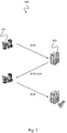
- Fig. 1 shows a connection setup 100 of a TCP connection in a communication system with a client 101 and a server 103.
- the client 101 and the server 103 perform a so-called three-way handshake to establish the connection.
- the connection establishment is as follows: First, the client 101 sends to the server 103 a request SYN ("Synchronize"), whereby the client 101 is requested to send a response packet SYN-ACK to the server 103. For this purpose, the source network address of the client 101 is transmitted with the request SYN as the reply network address.
- the server 103 then sends to the client 101 a response packet SYN-ACK ("Synchronize Acknowledge").
- a flag is a binary variable or status indicator that can be used as a tool to identify certain states.
- a flag can be set, deleted or read out.
- the client 101 transmits a reply network address that is different from the source network address of the client 101.
- the server 103 then responds with SYN-ACK packets to the SYN requests, these SYN-ACK packets now being sent out to the spoofed response network addresses. As a result, ACK responses are not transmitted to the server 103, but the server 103 is waiting for them. However, resources of the server 103 are used up, so that with a larger number of such requests, the free resources of the server 103 are used up so that the server 103 can no longer establish new connections, which leads to denial of service.
- the present invention is based on the recognition that the fake response addresses used in DoS attacks are often randomly chosen by one or more attackers. For this reason, as the number of outgoing requests and thus the different response addresses increases, so does the likelihood that the SYN-ACK response packets sent by a compromised server will receive unsolicited response packets from a monitoring server monitoring one or more, e.g., several 100 network addresses can be. To detect a DoS attack, therefore, the unsolicited receipt of a single response packet under the response network address used for a DoS attack is sufficient.
- a monitoring server is provided, to which one or more, for example several 100 network addresses, for example from an address space, are assigned. If the monitoring server receives a response packet that is not included by the monitoring server in response to a request that was not requested by the monitoring server, this indicates a fake reply address and thus a denial-of-service attack.
- the larger the address space, ie the The number of monitored network addresses that the monitoring server can monitor is the higher the likelihood that a fake source address will fall into that address space as a response address and the monitoring server may detect the DoS attack as outlined above.
- a server we refer to a computer that provides computing power, memory, data and services and manages access rights. In most cases, it is a very powerful computer, equipped with hardware and software depending on the application. Several services and applications can be executed on the server, which can be requested by other network participants over the network.
- a network entity or entity is a unit, entity, or entity in a communication network that can receive signals from the communication network and / or send signals to the communication network.
- a network or communication entity may be, for example, a server, a modem, a network card, a network termination, or a network adapter.
- a network or communication entity may include hardware and / or software to implement the technical functions of the communication entity.
- the network or communication entity may include microprocessors, microchips, ASICs, and / or DSPs.
- Transmission Control Protocol / Internet Protocol is a family of network protocols, also known as the Internet Protocol family.
- the identification of the computers participating in the network, which are also referred to as hosts, is done via IP addresses.
- IP Internet Protocol
- the IP is the first layer of the Internet Protocol family independent of the transmission medium.
- IP address and subnet mask for IPv4 see RFC 791
- prefix length in IPv6 see RFC 2460
- computers within one Network can be grouped into logical units, called subnets. This makes it possible to address computers in larger networks and to send them IP packets, since logical addressing is the basis for routing (routing and forwarding of network packets).
- TCP Transmission Control Protocol (see RFC 793).
- RFC 793 Transmission Control Protocol
- TCP is a reliable, connection-oriented, packet-switched transport protocol in computer networks. It is part of the Internet Protocol family.
- UDP User Datagram Protocol or user data segment protocol (see RFC 768).
- UDP is a minimal, connectionless network protocol that belongs to the transport layer of the Internet protocol family. UDP's job is to send data that is transmitted over the Internet to the right application.
- DNS Domain Name System
- ICMP Internet Control Message Protocol (see RFC 792).
- ICMP is used in computer networks to exchange information and error messages via the Internet Protocol.
- Ping is a diagnostic tool that can be used to verify that a particular host is accessible on an IP network. Ping sends an ICMP "echo-request” packet, also called “ping", to the destination address of the host to be checked. If the recipient supports the protocol, the recipient must return a response, ie an ICMP "Echo-Reply” also called “Pong”.
- HTTP Hypertext Transfer Protocol
- WWW World Wide Web
- the invention relates to a method for detecting a denial of service attack in a communication network in which an attacker with a source network address sends a request with a response network address to a destination server to send a response packet to the response network address from the destination server wherein the response network address is different from the source network address of the attacker, the target server sending a response packet to the response network address in response to receiving the request, and the method comprising the steps of: receiving a data packet from the destination server by a monitoring server the answer network address is assigned; and outputting a warning signal by the monitoring server if the received data packet is a response packet received unsolicited by the monitoring server.
- the request may be a connection request, for example a TCP connection request or a DNS request or DNS connection request or a UDP request or UDP connection request.
- the advantage of such a method is that the monitoring server can be set up like any client in the communication network.
- the monitoring server can thus be easily installed without reconfiguration of the communication network.
- the monitoring server only needs to receive data packets and can use a simple evaluation method to determine whether the received packet is an unsolicited reply packet.
- a destination network address of the destination server is extracted from the received data packet and displayed by the warning signal.
- the advantage of such a method is that it can both indicate that a denial-of-service attack is taking place and the target of the DoS attack can be determined.
- the operator of the communication network is thus promptly warned and has the opportunity to carry out appropriate countermeasures on or with the attacked destination server.
- the warning signal is sent out via a communication network to the destination server or to a network monitoring entity by another network entity, which is different from the monitoring server, in order to indicate the presence of a denial of service attack.
- the advantage of such a method is that it does not expose the monitoring server and does not become the target of DoS attacks.
- the communication network over which the alert signal is sent to the destination server may be a different communication network than that which the monitoring server controls.
- a plurality of different response network addresses are assigned to the monitoring server, wherein the majority of the different response network addresses are monitored by the monitoring server in order to detect the reception of the data packet.
- the advantage of such a method is that with a plurality of network addresses assigned to the monitoring server, the probability of receiving a packet provided with a fake source address is greater, so that detection of a DoS attack can be faster.
- the method comprises receiving by the monitoring server a plurality of data packets, wherein the received data packets have been sent by the destination server to response network addresses associated with the monitoring server; detecting a number of response packets in the plurality of data packets received by the monitoring server unsolicited; and outputting the warning signal by the monitoring server if the number of detected response packets reaches or exceeds a predetermined threshold.
- the advantage of such a method is that the reliability of the detection of a DoS attack is higher when a plurality of received data packets are available for evaluation.
- a data packet received by the monitoring server is an unsolicited response packet if the received response packet is not due to a request sent by the monitoring server to the destination server or if the received response packet originates from the destination server.
- the advantage of such a method is that an unsolicited response packet can be easily recognized.
- the monitor server only needs to create a store of sent requests and compare whether the received response packets were received in response to any of the requests held in memory.
- Such a memory can be, for example, the memory of the network stack in which open requests are stored. If the monitoring server only receives packets but does not send them out, the process is even easier. In that case, each received packet represents either a request or an unsolicited response packet. In the case of a response packet to the network address of the surveillance server, it can immediately detect a DoS attack.
- the method comprises determining whether the received response packet is due to a request sent by the monitoring server to the destination server; and identifying the received response packet as an unsolicited response packet if the received response packet is not due to a request sent by the monitoring server to the destination server.
- the advantage of such a method is that determining whether the received response packet is due to a request sent by the monitoring server to the destination server is easy to perform, as indicated above.
- the tagging can be done by the monitoring server either by setting a flag in the received packet, which has the advantage that the warning signal is transmitted via the Communication network can be disseminated or the monitoring server can perform the labeling on the sending of a message in an external network, which has the advantage that the communication network in which the attacker acts, is not affected, so that the attacker continues to feel safe and thus can be identified more easily.
- the received response packet is one of the following response packets: a synchronization acknowledgment SYN-ACK of the TCP transmission control protocol, the request being a synchronization request SYN of the TCP transmission control protocol; an ICMP echo data packet, in particular an ICMP data packet of the Echo Request type; a DNS data packet; or a User Datagram Protocol data packet.
- the advantage of such a method is that it can be used effectively on all common network protocols based on request and acknowledgment messages and / or response messages.
- the invention relates to a computer program with a program code for carrying out such a method when the program code is executed by means of a data processing system.
- the invention relates to a monitoring server for detecting a denial of service attack in a communication network in which an attacker with a source network address sends a request with a response network address to a destination server to send a response packet to the response network address from the destination server wherein the response network address is different from the attacker's source network address, wherein the destination server sends a response packet to the response network address in response to receiving the request, at least one response network address associated with the monitoring server, and wherein the monitoring server comprises the following features: a receiving interface for receiving a data packet originating from the destination server to a response address of the monitoring server; and a processor device configured to output a warning signal if the received data packet is a response packet received unsolicited by the monitoring server.
- the advantage of such a monitoring server is that the monitoring server can be set up like any client in the communication network.
- the monitoring server can thus be easily installed without reconfiguration of the communication network.
- the monitoring server only needs to receive data packets and can use a simple evaluation method to determine whether the received packet is an unsolicited reply packet.
- the monitoring server is assigned a plurality of different response network addresses, or the monitoring server is configured to manage a plurality of different response network addresses.
- the advantage of such a monitoring server is that with a plurality of network addresses allocated to the monitoring server or managed by the monitoring server, the probability of receiving a packet provided with a fake source address is greater, so that the detection of a DoS attack can be faster.
- the receiving interface is configured to receive a plurality of data packets originating from the destination server; and the processor is configured to detect a number of response packets in the plurality of data packets that have been received unsolicited by the monitoring server, wherein the processor is further configured to issue a warning signal if the number of detected response packets reaches or exceeds a predetermined threshold.
- the advantage of such a monitoring server is that the reliability of detection of a DoS attack is higher when a plurality of received data packets are available for evaluation.
- the processor is configured to determine whether the received response packet is due to a request sent by the monitoring server to the destination server; and flag the received response packet as an unsolicited response packet if the received response packet is not due to a request sent by the monitoring server to the destination server.
- the advantage of such a monitoring server is that determining whether the received response packet is due to a request sent by the monitoring server to the destination server is easy to perform.
- the tagging can be done by the monitoring server either by setting a flag in the received packet, which has the advantage that the warning signal can be transmitted easily and quickly over the communication network or the monitoring server can perform the tagging by sending a message in an external network, which has the advantage that the communication network in which the attacker acts is not affected, so that the attacker continues to feel safe and thus easier to identify.
- the receiving interface or the processor has a packet filter which is designed to filter response packets in the received data packets, in particular to filter exclusively response packets in the received data packets.
- the advantage of such a monitoring server is that the response packets can be easily recognized by the packet filter.
- the packet filter is easy to implement and quickly detects syn-ack and other response messages. For this purpose, only the various possible transmission protocols must be recognized, which is usually possible by querying a data field in the header and then checked by specified by the protocol body, whether an acknowledgment (Ack) or a request is present.
- the packet filter can be realized, for example, on today's network processors, for example as Mikrocoderealmaschine.
- the receiving interface is set up exclusively for the reception of data packets.
- monitoring server The advantage of such a monitoring server is that the exclusive reception of data packets, the detection of unrequested received response packets is easy to implement. Either request packets are received or are response packets, which are then unprompted, since the exclusive receipt of data packets no previous sending of a request by the monitoring server can be present. Such a monitoring server can be implemented particularly easily and with little effort.
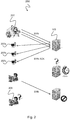
- Fig. 2 shows a SYN flooding ("flooding") attack on a computer system.
- the attack uses the connection establishment of the TCP transport protocol as in Fig. 1 shown to disable individual services or entire computers from the network or make them inaccessible.
- a malicious server or attacker 201 creates SYN packets where the source address is not its own. Instead, it fakes the source address so that the source addresses of other clients 207a, 207b, 207c present on the Internet are entered in the sent SYN packets.
- the server 203 then responds with SYN-ACK packets to the SYN requests, these SYN-ACK packets now being sent to the clients 207a, 207b, 207c.
- These clients 207a, 207b, 207c thus receive SYN-ACK response packets with respect to which they have not sent a request.
- the SYN-ACK packets are therefore considered to be unsolicited and are not further processed so that ACK responses to the server 103 are not generated.
- the server 103 waits some time for a corresponding packet, since it could arrive late because of delays. During this time, both the (fake) addresses of the clients 207a, 207b, 207c and the status of the half-open connection are kept in the memory of the network stack of the server 103 in order to establish the connection later completely. In all operating systems, this so-called semi-open connection occupies resources on the server 103.
- FIG. 12 shows a schematic representation of a communication network 300 with a monitoring server 103 for detecting a denial-of-service attack according to an embodiment.
- the attack is the same as above Fig. 2 described, ie a malicious attacker 201, such as a server or a client, in particular a client in a bot network, creates SYN packets where the source address is not his own and sends a variety of such packets to the server 103 in the communication network 300 the intention to paralyze him.
- the attacker 201 does not specify the same source address each time but uses different source addresses, which are assigned to a large number of clients 207a, 207b, 301, in order to simulate a high data volume.
- One of the clients 207a, 207b, 301 in the communication network 300 is a monitoring server 301 that is capable of detecting whether the SYN-ACK packet sent to it is an unsolicited response packet received.
- the monitoring server 301 can be equipped with a memory in which previously sent request messages or packets are buffered in order to query the memory for the corresponding request message upon receipt of a confirmation message or a response packet.
- a memory can be, for example, the memory of the network stack in which open requests are stored. If there is no associated request in memory for a confirmation, then it is an unsolicited confirmation message received.
- the monitoring server 301 may detect a DoS attack upon receipt of such an unsolicited acknowledgment message and, if necessary, raise an alarm.
- the monitoring server 301 is configured to detect a denial-of-service attack in a communication network 300 in which an attacker 201 having a source network address makes a request, e.g. sends a SYN packet, with a reply network address to a destination server 103, to send from the destination server 103 a response packet, e.g. a SYN-ACK packet, to the response network address, e.g. request one of the addresses of the clients 207a, 207b, 301, wherein the reply network address is different from the source network address of the attacker 201.
- an attacker 201 having a source network address makes a request, e.g. sends a SYN packet, with a reply network address to a destination server 103, to send from the destination server 103 a response packet, e.g. a SYN-ACK packet, to the response network address, e.g. request one of the addresses of the clients 207a, 207b, 301, wherein the reply network address is
- the destination server 103 then sends a response packet (e.g., SYN-ACK) to the response network address, such as the addresses of the clients 207a, 207b, 301, in response to receiving the request (e.g., SYN).
- the monitoring server 301 is capable of receiving a data packet (eg, SYN-ACK) originating from the destination server 103 to a response address of the monitoring server 301 and outputting an alarm or a warning signal if the received data packet (SYN-ACK) is received by the monitoring server 301 is unanswered received response packet (SYN-ACK).
- a received data packet may be an unsolicited response packet if the received response packet (SYN-ACK) is not due to a request sent by the monitoring server 301 to the destination server 103 and / or if the received response packet SYN-ACK of originates the destination server 103.
- the monitoring server 301 may, for example, extract from the received data packet a destination network address of the destination server 103 and display it by the warning signal.
- the warning signal may be displayed to indicate that a denial of service attack has occurred.
- the warning signal can also be forwarded to a specific network monitoring device, for example by another server, to indicate to the network monitoring device the existence of a DoS attack. In this case, the monitoring server 301 may operate hidden, ie it will not be unmasked.
- the received response packets need not be exclusively TCP ACK packets.
- the monitoring server 301 may also receive other response packets and, based thereon, detect a DoS attack, for example an ICMP echo data packet, in particular an ICMP data packet of the Echo Reply type, which is typically sent in response to a ping request, a DNS data packet User Datagram Protocol (UDP) data packet or response packets of other data protocols.
- a DoS attack for example an ICMP echo data packet, in particular an ICMP data packet of the Echo Reply type, which is typically sent in response to a ping request, a DNS data packet User Datagram Protocol (UDP) data packet or response packets of other data protocols.
- UDP User Datagram Protocol
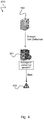
- Fig. 4 shows a schematic representation of one in the monitoring server Fig. 3 expiring method 400 to detect a denial of service attack, according to one embodiment.
- the monitoring server 301 Upon receipt of a confirmation message from the destination server 103, the monitoring server 301 checks whether the message is a response to a previously made by him request to the destination server 103. If this is not the case, it is most likely a denial of service attack. The monitoring server 301 generates an alarm 402 or a warning message.
- the TCP segment consists of two parts, the header (data header) and the payload, also called payload.
- the payload contains the data to be transmitted and the header contains data required for the communication as well as the file format descriptive information.
- a typical header may be 20 bytes in size.
- the TCP header includes a 2-byte field indicating the source port on the sender side, a 2-byte field indicating the destination port on the receiver side, a 4-byte field containing the sequence number of this TCP packet, or the initialization sequence number SYN flag is set, indicates a 4-byte field indicating the acknowledgment number, ie, the sequence number that the receiver of that TCP segment expects next and a 6-bit Control-Flags field to use to mark important states for the communication and further processing of the data.
- the ACK flag also referred to as acknowledgment flag or acknowledgment flag, has, in conjunction with the acknowledgment number, the task of confirming the reception of TCP segments during the data transfer.
- the acknowledgment number is only valid if the flag is set.
- the SYN flag is used to initiate a connection. Packages with a set SYN flag initiate a connection. The server usually responds with either SYN + ACK when it is ready to accept the connection, otherwise with RST.
- the SYN flag is used to synchronize sequence numbers when establishing a connection.
- the RST flag also called reset flag, is used when a connection is to be aborted. This occurs, for example, in the case of technical problems or to reject unwanted connections, such as ports that are not open.
- the monitoring server 301 can, for example, read the TCP header when receiving a TCP packet and query the ACK flag and the SYN flag there. If these two flags are set, this is a confirmation of a previous request. The monitoring server 301 may then look in its memory to see if there is an associated TCP request packet, i. a TCP packet with set SYN flag, its acknowledgment number, i. whose sequence number the receiver next expects matches the sequence number in the received TCP request packet. If there is no match, the monitoring server 301 may generate a warning 402.
- Such a memory can be, for example, the memory of the network stack in which open requests are stored.
- the monitoring server 301 may also additionally send a response to the destination server 103 to indicate that a denial-of-service attack has been detected.
- the monitoring server 301 may also send a response to the response packet, such as a TCP packet, with the RST flag set to signal the destination server to terminate the connection.
- this response may include a predefined flag that tells target server 103 that the connection abort is due to DoS Attack.
- the ICMP segment In the case of a ping request that is executed with the ICMP protocol, the ICMP segment consists of a header and the data.
- the header consists of a type data field, a code data field and a checksum data field.
- the type data field contains an 8, while for the echo response it has a 0.
- the monitoring server 301 can, for example, read the ICMP header when receiving an ICMP data packet and query the type data field there. If this is set to 0, then it is an ICMP Echo Reply packet, ie a confirmation (Pong) on a previous request. The monitoring server 301 may then look in its memory for an associated ICMP request packet (ping), ie an ICMP packet with the packet type 0x08. Such a memory can be, for example, the memory of the network stack in which open requests are stored. If no such request packet exists, the monitoring server 301 may generate a warning 402. In addition to the warning message, the monitoring server 301 can also additionally send a message to the destination server 103 to indicate that a denial-of-service attack has been detected.
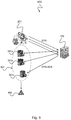
- FIG. 12 shows a schematic representation of a communications network 500 having a monitoring server 301 associated with a plurality of network addresses for detecting a denial-of-service attack according to an embodiment.
- the monitoring server 301 may have a plurality of network addresses so as to simulate a plurality of clients.
- a monitoring server 301 to which a plurality of addresses are assigned thus corresponds to a communication network with a plurality of monitoring servers 301 a, 301 b, 301 c, to each of which (different) addresses are assigned, as in FIG Fig. 5 shown. If the attacker 201 sends request packets with forged source addresses, the probability of detection increases if the monitoring server can receive requests from a pool of network addresses or IP addresses.
- the replies to the requests with the spoofed source addresses generated by the attacker 201 will, if they are randomly generated network addresses or IP addresses, most likely be addressed to one of the network addresses in the address pool of the monitoring server 301 if the The address pool of the monitoring server 301 is very large, for example, has the size of a class C, class B or even class A network.
- the monitoring server 301 may monitor the plurality of different response network addresses to detect receipt of an unsolicited received data packet.
- the monitoring server 301 can proceed as follows. First, a data packet or the plurality of data packets received by the destination server 103 may be sent to response network addresses associated with the monitoring server 301. Thereafter, it can detect the number of response packets in the plurality of data packets that were received unsolicited. Finally, it can issue a warning signal if the number of detected response packets reaches or exceeds a predetermined threshold.
- This takes into account that the receipt of unsolicited response packets can also be random packets or packets whose data was randomly corrupted when transmitted over the channel. For example, sending an alarm can only take place when, based on a predetermined number of unsolicited packets, a DoS attack can be concluded with a certain degree of certainty. This increases the reliability of detection and avoids any false alarms.
- a data packet received by the monitoring server 301 may be considered an unsolicited response packet if the received response packet is not due to a request sent by the monitoring server to the destination server or if the received response packet originates from the destination server.
- the monitoring server 301 is between the destination server 103 and one or more of the clients 207a, 207b from the illustration of FIG. 3 localized so that it can read request and acknowledgment messages to the clients 207a, 207b and determine based on whether an acknowledgment has been made on a request from the respective client or not. If not, it is an unsolicited confirmation message.
- the monitoring server 301 monitors the communication between the destination server 103 and one Plurality of clients 207a, 207b to detect unsolicited acknowledgment messages. The monitoring server 301 only needs to listen to the messages without having any influence on the network connections.
- Fig. 6 shows a schematic representation of one in the monitoring server Fig. 5 expiring method 600 to detect a denial of service attack, according to one embodiment.
- the monitoring server 301 checks on arrival of a confirmation message from the destination server 103, if the message is a response to a previously made by him request to the destination server 103. If this is not the case, it is most likely a denial of service attack.
- the monitoring server 301 generates an alarm 402 or a warning message.
- the monitoring server 301 performs this mechanism for all the addresses associated with it, ie the entire address pool 601 of the in Fig. 6 represented addresses 1 to N, from. If the address space of the address pool 601 is large, then the probability that one of the fake source addresses of the DoS attack is one of the addresses from the address pool 601 of the monitoring server 301.
- the monitoring server 301 may determine, for each received packet of one of its associated addresses, whether the received response packet is due to a request sent by the monitoring server to the destination server and identifying the received response packet as an unsolicited response packet if the received response packet does not match one received by the one Monitoring server sent to the destination server.
- the monitoring server 301 may include a packet filter to filter the received packets, for example, the packet filter may only pass received response packets for further processing and discard other packets that are not response packets. This ensures faster processing by the monitoring server because response packets allow the monitoring server to determine if the acknowledgment was requested or sent unsolicited. For example, in a first stage, such a packet filter can only pass the packet header (packet header) for further processing and, in a second stage, in the packet header looking for a confirmation flag to detect a received packet as a response packet.
- the packet filter can detect and forward the TCP header in the first stage, whereupon in the second stage in the TCP header, the SYN flag and the ACK flag are detected, each at the same position in the TCP Headers are to be found. If both flags are set, then this is a SYN-ACK response packet which can be compared to a request packet present in memory, as in above Fig. 4 described in order to detect or filter out an unsolicited response packet.
- both stages of the packet filter can also be implemented as a single filtering operation, so that the packet filter filters out the acknowledgment flags (SYN flag and ACK flag) at the predetermined location when the type of data packet (eg, TCP) is recognized.
- the packet filter may filter out the IGMP header in a first stage and in a second stage the type data field, i. read out the packet type to detect an ICMP Echo Reply packet in an ICMP packet type of 0x00, that is a reply packet and then compare this to an ICMP Echo Request packet with packet type 0x08 present in the memory to receive an unsolicited ICMP echo Reply packet (Pong) to detect or filter out.
- a memory can be, for example, the memory of the network stack in which open requests are stored. Both stages of the packet filter can also be executed here as a single filtering operation, so that the packet filter can immediately filter out the packet type at the predetermined location when the type of data packet (eg ICMP echo) is recognized.
- the packet filter can filter out a DNS response packet.
- the malicious client passes the name resolution to a DNS server using a DNS request packet with a fake source address. If the DNS server can not resolve the domain name, the DNS server will ask other DNS servers until the domain name is resolved and the response from the DNS server can be returned to the spoofed client.
- the fake client is the monitoring server 301, then it receives the DNS response packet that can be filtered out by the packet filter by one Determine DoS attack.
- the DNS server returns only the address of the next DNS server to be queried.
- the packet filter of the monitoring server 301 is able to filter the received data packet, so that the monitoring server 301 can recognize from the received DNS packet with the supplied address of the next DNS server whether the received DNS packet is an unsolicited DNS packet, to detect a DoS attack.
- the packet filter may filter out an HTTP response data packet and the monitoring server 301 may check whether it can be associated with a previously sent HTTP request data packet.
- the packet filter can also filter out an SNMP Get Response data packet and the monitoring server 301 can check if it can be assigned to a previously sent SNMP Get Request data packet.
- a DoS attack can be detected in the same way by the monitoring server 301.
- the monitoring server 301 can, for example, receive data packets with a reception interface, wherein the reception interface can be set up exclusively for the reception of data packets. Also, if the monitoring server 301 receives only data packets but does not return responses to received data packets, then it can not be unmasked because it then only monitors the traffic without affecting it. Without affecting the traffic, it is not easy to detect its presence, especially from an attacker on the network.
- FIG. 12 shows a schematic representation of a monitoring server 301 for detecting a denial-of-service attack in a communication network according to one embodiment.
- An attacker (not shown) with a source network address sends a request with a response network address to the destination server 203 to request from the destination server 203 to send a response packet to the response network address.
- the response network address may be different from the source network address of the attacker.
- the destination server sends a response packet to the response network address in response to receiving the request.
- At least one answer network address is assigned to the monitoring server 301.
- the monitoring server 301 includes a receiving interface 701 for receiving a
- the monitoring server 301 further comprises a processor device 703, which is configured to output a warning signal 704 if the received data packet is an unsolicited response packet received by the monitoring server 301.
- the monitoring server 301 may be associated with a plurality of different response network addresses, for example as described above with respect to FIG Figures 5 and 6 described.
- the monitoring server 301 may alternatively or additionally manage a plurality of different response network addresses.
- the receiving interface 701 may receive a plurality of data packets originating from the destination server 203.
- the processor 703 may detect a number of response packets in the plurality of data packets received by the monitoring server 301 unsolicited.
- the processor 703 may also issue a warning signal if the number of detected response packets reaches or exceeds a predetermined threshold.
- the processor 703 may determine whether the received response packet is due to a request sent by the monitoring server 301 to the destination server 203; and flag the received response packet as an unsolicited response packet if the received response packet is not due to a request sent by the monitoring server 301 to the destination server 203.
- the receiving interface 701 and / or the processor 703 may comprise a packet filter which can filter response packets in the received data packets, in particular exclusively response packets in the received data packets to detect the response packets, for example SYN-ACK, ICMP Echo Reply, or other acknowledgments.
- the reception interface 701 can be set up exclusively for the reception of data packets.
- the receive interface 701 and / or the processor 703 may be mapped to various devices / servers.
- correlations are possible, which allow further conclusions on the attack method or the attacker.
- several levels can be established for this purpose: sensors -> aggregator (s) -> normalizer (s) -> database (s) -> analyzer (s).
- the processor 703 may, for example, be realized as a hardware circuit, for example as a controller or a DSP or an ASIC or an FPGA.
- the processor may be implemented on a chip or an integrated circuit or IC.
- the receiving interface 701 may be a memory or register in which data words received by an A / D converter are stored.
- FIG. 12 shows a schematic representation of a method 800 for detecting a denial-of-service attack according to an embodiment.
- the method 800 is adapted to detect a denial-of-service attack in a communication network in which an attacker with a source network address sends a request with a response network address to a destination server to request the destination server to send a response packet to the response network address wherein the response network address is different from the source network address of the attacker, and wherein the destination server sends a response packet to the response network address in response to receiving the request.
- the method 800 comprises receiving 801 a data packet originating from the destination server by a monitoring server to which the response network address is assigned; and outputting 802 a warning signal by the monitoring server if the received data packet is a response packet received unsolicited by the monitoring server.
- a destination network address of the destination server is extracted from the received data packet and displayed by the warning signal.
- the warning signal is sent out over a communication network to the destination server or to a network monitoring entity by another network entity different from the monitoring server to indicate the existence of a denial-of-service attack display. This will not expose the monitoring server.
- the monitoring server is associated with a plurality of different response network addresses, wherein the plurality of different response network addresses are monitored by the monitoring server to detect receipt of the data packet.
- the method 800 comprises receiving a plurality of data packets by the monitoring server, wherein the received data packets have been sent by the destination server to response network addresses associated with the monitoring server; detecting a number of response packets in the plurality of data packets received by the monitoring server unsolicited; and outputting the warning signal by the monitoring server if the number of detected response packets reaches or exceeds a predetermined threshold.
- a data packet received by the monitoring server is an unsolicited response packet if the received response packet is not due to a request sent by the monitoring server to the destination server, or if the received response packet originates from the destination server.
- the method 800 includes determining whether to return the received response packet to a request sent by the monitoring server to the destination server; and identifying the received response packet as an unsolicited response packet if the received response packet is not due to a request sent by the monitoring server to the destination server.
- the received response packet is one of the following response packets: a synchronization acknowledgment SYN-ACK of the TCP transmission control protocol, the request being a synchronization request SYN of the TCP transmission control protocol; an ICMP echo data packet, in particular an ICMP data packet of the Echo Reply type; a DNS data packet or a or multiple DNS response packets as a subset of User Datagram Protocol data packets; or a User Datagram Protocol data packet.
Landscapes
- Engineering & Computer Science (AREA)
- Computer Security & Cryptography (AREA)
- Computer Hardware Design (AREA)
- Computing Systems (AREA)
- General Engineering & Computer Science (AREA)
- Computer Networks & Wireless Communication (AREA)
- Signal Processing (AREA)
- Data Exchanges In Wide-Area Networks (AREA)
- Computer And Data Communications (AREA)
Priority Applications (2)
| Application Number | Priority Date | Filing Date | Title |
|---|---|---|---|
| EP16165013.0A EP3059926B1 (fr) | 2013-12-30 | 2013-12-30 | Procédé de détection d'une attaque par déni de service dans un réseau de communication |
| PL16165013T PL3059926T3 (pl) | 2013-12-30 | 2013-12-30 | Sposób rozpoznawania ataku Denial of Service w sieci komunikacyjnej |
Applications Claiming Priority (2)
| Application Number | Priority Date | Filing Date | Title |
|---|---|---|---|
| EP16165013.0A EP3059926B1 (fr) | 2013-12-30 | 2013-12-30 | Procédé de détection d'une attaque par déni de service dans un réseau de communication |
| EP13199823.9A EP2890072B1 (fr) | 2013-12-30 | 2013-12-30 | Procédé de détection d'une attaque par déni de service dans un réseau de communication |
Related Parent Applications (1)
| Application Number | Title | Priority Date | Filing Date |
|---|---|---|---|
| EP13199823.9A Division EP2890072B1 (fr) | 2013-12-30 | 2013-12-30 | Procédé de détection d'une attaque par déni de service dans un réseau de communication |
Publications (2)
| Publication Number | Publication Date |
|---|---|
| EP3059926A1 true EP3059926A1 (fr) | 2016-08-24 |
| EP3059926B1 EP3059926B1 (fr) | 2017-08-16 |
Family
ID=49882959
Family Applications (2)
| Application Number | Title | Priority Date | Filing Date |
|---|---|---|---|
| EP13199823.9A Active EP2890072B1 (fr) | 2013-12-30 | 2013-12-30 | Procédé de détection d'une attaque par déni de service dans un réseau de communication |
| EP16165013.0A Active EP3059926B1 (fr) | 2013-12-30 | 2013-12-30 | Procédé de détection d'une attaque par déni de service dans un réseau de communication |
Family Applications Before (1)
| Application Number | Title | Priority Date | Filing Date |
|---|---|---|---|
| EP13199823.9A Active EP2890072B1 (fr) | 2013-12-30 | 2013-12-30 | Procédé de détection d'une attaque par déni de service dans un réseau de communication |
Country Status (3)
| Country | Link |
|---|---|
| EP (2) | EP2890072B1 (fr) |
| PL (2) | PL3059926T3 (fr) |
| WO (1) | WO2015101572A1 (fr) |
Families Citing this family (2)
| Publication number | Priority date | Publication date | Assignee | Title |
|---|---|---|---|---|
| CN111478922B (zh) * | 2020-04-27 | 2023-02-03 | 深信服科技股份有限公司 | 一种隐蔽信道通信检测方法、装置及设备 |
| CN116915518B (zh) * | 2023-09-14 | 2023-12-01 | 国网浙江省电力有限公司电力科学研究院 | 一种智能学习式自应答联网蜜罐诱导方法及系统 |
Citations (3)
| Publication number | Priority date | Publication date | Assignee | Title |
|---|---|---|---|---|
| US20060280121A1 (en) * | 2005-06-13 | 2006-12-14 | Fujitsu Limited | Frame-transfer control device, DoS-attack preventing device, and DoS-attack preventing system |
| US7971253B1 (en) * | 2006-11-21 | 2011-06-28 | Airtight Networks, Inc. | Method and system for detecting address rotation and related events in communication networks |
| US20130111589A1 (en) * | 2011-10-28 | 2013-05-02 | Samsung Sds Co., Ltd. | System and method for detecting address resolution protocol (arp) spoofing |
-
2013
- 2013-12-30 EP EP13199823.9A patent/EP2890072B1/fr active Active
- 2013-12-30 PL PL16165013T patent/PL3059926T3/pl unknown
- 2013-12-30 PL PL13199823.9T patent/PL2890072T3/pl unknown
- 2013-12-30 EP EP16165013.0A patent/EP3059926B1/fr active Active
-
2014
- 2014-12-23 WO PCT/EP2014/079245 patent/WO2015101572A1/fr not_active Ceased
Patent Citations (3)
| Publication number | Priority date | Publication date | Assignee | Title |
|---|---|---|---|---|
| US20060280121A1 (en) * | 2005-06-13 | 2006-12-14 | Fujitsu Limited | Frame-transfer control device, DoS-attack preventing device, and DoS-attack preventing system |
| US7971253B1 (en) * | 2006-11-21 | 2011-06-28 | Airtight Networks, Inc. | Method and system for detecting address rotation and related events in communication networks |
| US20130111589A1 (en) * | 2011-10-28 | 2013-05-02 | Samsung Sds Co., Ltd. | System and method for detecting address resolution protocol (arp) spoofing |
Also Published As
| Publication number | Publication date |
|---|---|
| WO2015101572A1 (fr) | 2015-07-09 |
| EP2890072A1 (fr) | 2015-07-01 |
| EP2890072B1 (fr) | 2016-05-04 |
| PL2890072T3 (pl) | 2016-11-30 |
| EP3059926B1 (fr) | 2017-08-16 |
| PL3059926T3 (pl) | 2018-01-31 |
Similar Documents
| Publication | Publication Date | Title |
|---|---|---|
| DE60210408T2 (de) | Ueberwachung des Datenflusses zur Verbesserung des Netzwerksicherheitsschutzes | |
| DE69727447T2 (de) | Übertragungstrennung und Ebene-3-Netzwerk-Vermittlung | |
| EP3542511B1 (fr) | Processus pour un réseau de communication et unité de commande électronique | |
| DE60124295T2 (de) | Flussbasierte erfassung eines eindringens in ein netzwerk | |
| DE60127978T2 (de) | System und Verfahren zur Verteidigung gegen Denial-of-Service angriffe auf die Netzwerkknoten | |
| DE60310645T2 (de) | Verhinderung von Paketzerteilung | |
| DE202016009181U1 (de) | Regelbasierte Erkennung von Netzwerkbedrohungen für verschlüsselte Kommunikationen | |
| DE102019210229A1 (de) | Verfahren und Vorrichtung zur Analyse dienste-orientierter Kommunikation | |
| DE112012002054T5 (de) | Spoofing-Angriff-Abwehrverfahren unter Verwendung eines Blockierungsservers | |
| DE602004002198T2 (de) | Verfahren und Vorrichtung zur Verhinderung von Angriffen auf einen Call-Server | |
| WO2016008778A1 (fr) | Procédé de détection d'une attaque dans un réseau d'ordinateurs | |
| DE112016002952T5 (de) | Systeme und Verfahren zum Verarbeiten von Paketen in einem Computernetz | |
| EP1494401B1 (fr) | Routeur et procédé d'activation d'un ordinateur désactivé | |
| DE60313501T2 (de) | System und Verfahren zur Verwaltung passiver Netzwerkeinrichtungen unter Verwendung von Umsetzverbindungen | |
| EP3059926B1 (fr) | Procédé de détection d'une attaque par déni de service dans un réseau de communication | |
| DE102006004202B4 (de) | Verfahren zum Schutz von SIP basierten Anwendungen | |
| DE102019210223A1 (de) | Vorrichtung und Verfahren für Angriffserkennung in einem Rechnernetzwerk | |
| DE102019210224A1 (de) | Vorrichtung und Verfahren für Angriffserkennung in einem Rechnernetzwerk | |
| WO2022090064A1 (fr) | Procédé de surveillance d'un réseau de données dans un véhicule automobile, dispositif de commutation, et véhicule automobile | |
| EP3515034B1 (fr) | Procédés, dispositifs, supports lisibles par ordinateur et systèmes d'établissement des liaisons certifiées avec des terminaux dans un réseau local | |
| DE102019210226A1 (de) | Vorrichtung und Verfahren für Angriffserkennung in einem Kommunikationsnetzwerk | |
| DE102021127714B4 (de) | Verfahren und Vorrichtung zum Verhindern von böswilligem Netzverkehr | |
| DE102014109906A1 (de) | Verfahren zum Freischalten externer Computersysteme in einer Computernetz-Infrastruktur, verteiltes Rechnernetz mit einer solchen Computernetz-Infrastruktur sowie Computerprogramm-Produkt | |
| EP4080830B1 (fr) | Procédé de vérification et de commande d'un trafic de données sortant d'un terminal de réseau domestique compatible ip et système de communication | |
| EP4096170B1 (fr) | Procédé de transmission de données dans un système de réseau, ainsi que système de réseau |
Legal Events
| Date | Code | Title | Description |
|---|---|---|---|
| PUAI | Public reference made under article 153(3) epc to a published international application that has entered the european phase |
Free format text: ORIGINAL CODE: 0009012 |
|
| AC | Divisional application: reference to earlier application |
Ref document number: 2890072 Country of ref document: EP Kind code of ref document: P |
|
| AK | Designated contracting states |
Kind code of ref document: A1 Designated state(s): AL AT BE BG CH CY CZ DE DK EE ES FI FR GB GR HR HU IE IS IT LI LT LU LV MC MK MT NL NO PL PT RO RS SE SI SK SM TR |
|
| STAA | Information on the status of an ep patent application or granted ep patent |
Free format text: STATUS: REQUEST FOR EXAMINATION WAS MADE |
|
| 17P | Request for examination filed |
Effective date: 20170202 |
|
| RBV | Designated contracting states (corrected) |
Designated state(s): AL AT BE BG CH CY CZ DE DK EE ES FI FR GB GR HR HU IE IS IT LI LT LU LV MC MK MT NL NO PL PT RO RS SE SI SK SM TR |
|
| GRAP | Despatch of communication of intention to grant a patent |
Free format text: ORIGINAL CODE: EPIDOSNIGR1 |
|
| STAA | Information on the status of an ep patent application or granted ep patent |
Free format text: STATUS: GRANT OF PATENT IS INTENDED |
|
| INTG | Intention to grant announced |
Effective date: 20170323 |
|
| GRAS | Grant fee paid |
Free format text: ORIGINAL CODE: EPIDOSNIGR3 |
|
| GRAA | (expected) grant |
Free format text: ORIGINAL CODE: 0009210 |
|
| STAA | Information on the status of an ep patent application or granted ep patent |
Free format text: STATUS: THE PATENT HAS BEEN GRANTED |
|
| AC | Divisional application: reference to earlier application |
Ref document number: 2890072 Country of ref document: EP Kind code of ref document: P |
|
| AK | Designated contracting states |
Kind code of ref document: B1 Designated state(s): AL AT BE BG CH CY CZ DE DK EE ES FI FR GB GR HR HU IE IS IT LI LT LU LV MC MK MT NL NO PL PT RO RS SE SI SK SM TR |
|
| REG | Reference to a national code |
Ref country code: GB Ref legal event code: FG4D Free format text: NOT ENGLISH |
|
| REG | Reference to a national code |
Ref country code: CH Ref legal event code: EP |
|
| REG | Reference to a national code |
Ref country code: IE Ref legal event code: FG4D Free format text: LANGUAGE OF EP DOCUMENT: GERMAN |
|
| REG | Reference to a national code |
Ref country code: AT Ref legal event code: REF Ref document number: 920103 Country of ref document: AT Kind code of ref document: T Effective date: 20170915 |
|
| REG | Reference to a national code |
Ref country code: DE Ref legal event code: R096 Ref document number: 502013008111 Country of ref document: DE |
|
| REG | Reference to a national code |
Ref country code: NL Ref legal event code: FP |
|
| REG | Reference to a national code |
Ref country code: FR Ref legal event code: PLFP Year of fee payment: 5 |
|
| REG | Reference to a national code |
Ref country code: LT Ref legal event code: MG4D |
|
| PG25 | Lapsed in a contracting state [announced via postgrant information from national office to epo] |
Ref country code: LT Free format text: LAPSE BECAUSE OF FAILURE TO SUBMIT A TRANSLATION OF THE DESCRIPTION OR TO PAY THE FEE WITHIN THE PRESCRIBED TIME-LIMIT Effective date: 20170816 Ref country code: SE Free format text: LAPSE BECAUSE OF FAILURE TO SUBMIT A TRANSLATION OF THE DESCRIPTION OR TO PAY THE FEE WITHIN THE PRESCRIBED TIME-LIMIT Effective date: 20170816 Ref country code: NO Free format text: LAPSE BECAUSE OF FAILURE TO SUBMIT A TRANSLATION OF THE DESCRIPTION OR TO PAY THE FEE WITHIN THE PRESCRIBED TIME-LIMIT Effective date: 20171116 Ref country code: FI Free format text: LAPSE BECAUSE OF FAILURE TO SUBMIT A TRANSLATION OF THE DESCRIPTION OR TO PAY THE FEE WITHIN THE PRESCRIBED TIME-LIMIT Effective date: 20170816 |
|
| PG25 | Lapsed in a contracting state [announced via postgrant information from national office to epo] |
Ref country code: IS Free format text: LAPSE BECAUSE OF FAILURE TO SUBMIT A TRANSLATION OF THE DESCRIPTION OR TO PAY THE FEE WITHIN THE PRESCRIBED TIME-LIMIT Effective date: 20171216 Ref country code: RS Free format text: LAPSE BECAUSE OF FAILURE TO SUBMIT A TRANSLATION OF THE DESCRIPTION OR TO PAY THE FEE WITHIN THE PRESCRIBED TIME-LIMIT Effective date: 20170816 Ref country code: GR Free format text: LAPSE BECAUSE OF FAILURE TO SUBMIT A TRANSLATION OF THE DESCRIPTION OR TO PAY THE FEE WITHIN THE PRESCRIBED TIME-LIMIT Effective date: 20171117 Ref country code: BG Free format text: LAPSE BECAUSE OF FAILURE TO SUBMIT A TRANSLATION OF THE DESCRIPTION OR TO PAY THE FEE WITHIN THE PRESCRIBED TIME-LIMIT Effective date: 20171116 Ref country code: LV Free format text: LAPSE BECAUSE OF FAILURE TO SUBMIT A TRANSLATION OF THE DESCRIPTION OR TO PAY THE FEE WITHIN THE PRESCRIBED TIME-LIMIT Effective date: 20170816 Ref country code: ES Free format text: LAPSE BECAUSE OF FAILURE TO SUBMIT A TRANSLATION OF THE DESCRIPTION OR TO PAY THE FEE WITHIN THE PRESCRIBED TIME-LIMIT Effective date: 20170816 |
|
| PG25 | Lapsed in a contracting state [announced via postgrant information from national office to epo] |
Ref country code: RO Free format text: LAPSE BECAUSE OF FAILURE TO SUBMIT A TRANSLATION OF THE DESCRIPTION OR TO PAY THE FEE WITHIN THE PRESCRIBED TIME-LIMIT Effective date: 20170816 Ref country code: CZ Free format text: LAPSE BECAUSE OF FAILURE TO SUBMIT A TRANSLATION OF THE DESCRIPTION OR TO PAY THE FEE WITHIN THE PRESCRIBED TIME-LIMIT Effective date: 20170816 Ref country code: DK Free format text: LAPSE BECAUSE OF FAILURE TO SUBMIT A TRANSLATION OF THE DESCRIPTION OR TO PAY THE FEE WITHIN THE PRESCRIBED TIME-LIMIT Effective date: 20170816 |
|
| REG | Reference to a national code |
Ref country code: DE Ref legal event code: R097 Ref document number: 502013008111 Country of ref document: DE |
|
| PG25 | Lapsed in a contracting state [announced via postgrant information from national office to epo] |
Ref country code: SM Free format text: LAPSE BECAUSE OF FAILURE TO SUBMIT A TRANSLATION OF THE DESCRIPTION OR TO PAY THE FEE WITHIN THE PRESCRIBED TIME-LIMIT Effective date: 20170816 Ref country code: EE Free format text: LAPSE BECAUSE OF FAILURE TO SUBMIT A TRANSLATION OF THE DESCRIPTION OR TO PAY THE FEE WITHIN THE PRESCRIBED TIME-LIMIT Effective date: 20170816 Ref country code: IT Free format text: LAPSE BECAUSE OF FAILURE TO SUBMIT A TRANSLATION OF THE DESCRIPTION OR TO PAY THE FEE WITHIN THE PRESCRIBED TIME-LIMIT Effective date: 20170816 Ref country code: SK Free format text: LAPSE BECAUSE OF FAILURE TO SUBMIT A TRANSLATION OF THE DESCRIPTION OR TO PAY THE FEE WITHIN THE PRESCRIBED TIME-LIMIT Effective date: 20170816 |
|
| PLBE | No opposition filed within time limit |
Free format text: ORIGINAL CODE: 0009261 |
|
| STAA | Information on the status of an ep patent application or granted ep patent |
Free format text: STATUS: NO OPPOSITION FILED WITHIN TIME LIMIT |
|
| 26N | No opposition filed |
Effective date: 20180517 |
|
| REG | Reference to a national code |
Ref country code: CH Ref legal event code: PL |
|
| PG25 | Lapsed in a contracting state [announced via postgrant information from national office to epo] |
Ref country code: SI Free format text: LAPSE BECAUSE OF FAILURE TO SUBMIT A TRANSLATION OF THE DESCRIPTION OR TO PAY THE FEE WITHIN THE PRESCRIBED TIME-LIMIT Effective date: 20170816 |
|
| PG25 | Lapsed in a contracting state [announced via postgrant information from national office to epo] |
Ref country code: MT Free format text: LAPSE BECAUSE OF FAILURE TO SUBMIT A TRANSLATION OF THE DESCRIPTION OR TO PAY THE FEE WITHIN THE PRESCRIBED TIME-LIMIT Effective date: 20170816 Ref country code: LU Free format text: LAPSE BECAUSE OF NON-PAYMENT OF DUE FEES Effective date: 20171230 |
|
| REG | Reference to a national code |
Ref country code: IE Ref legal event code: MM4A |
|
| REG | Reference to a national code |
Ref country code: BE Ref legal event code: MM Effective date: 20171231 |
|
| PG25 | Lapsed in a contracting state [announced via postgrant information from national office to epo] |
Ref country code: IE Free format text: LAPSE BECAUSE OF NON-PAYMENT OF DUE FEES Effective date: 20171230 |
|
| PG25 | Lapsed in a contracting state [announced via postgrant information from national office to epo] |
Ref country code: BE Free format text: LAPSE BECAUSE OF NON-PAYMENT OF DUE FEES Effective date: 20171231 Ref country code: CH Free format text: LAPSE BECAUSE OF NON-PAYMENT OF DUE FEES Effective date: 20171231 Ref country code: LI Free format text: LAPSE BECAUSE OF NON-PAYMENT OF DUE FEES Effective date: 20171231 |
|
| PG25 | Lapsed in a contracting state [announced via postgrant information from national office to epo] |
Ref country code: MC Free format text: LAPSE BECAUSE OF FAILURE TO SUBMIT A TRANSLATION OF THE DESCRIPTION OR TO PAY THE FEE WITHIN THE PRESCRIBED TIME-LIMIT Effective date: 20170816 Ref country code: HU Free format text: LAPSE BECAUSE OF FAILURE TO SUBMIT A TRANSLATION OF THE DESCRIPTION OR TO PAY THE FEE WITHIN THE PRESCRIBED TIME-LIMIT; INVALID AB INITIO Effective date: 20131230 |
|
| REG | Reference to a national code |
Ref country code: DE Ref legal event code: R082 Ref document number: 502013008111 Country of ref document: DE |
|
| PG25 | Lapsed in a contracting state [announced via postgrant information from national office to epo] |
Ref country code: CY Free format text: LAPSE BECAUSE OF FAILURE TO SUBMIT A TRANSLATION OF THE DESCRIPTION OR TO PAY THE FEE WITHIN THE PRESCRIBED TIME-LIMIT Effective date: 20170816 |
|
| PG25 | Lapsed in a contracting state [announced via postgrant information from national office to epo] |
Ref country code: MK Free format text: LAPSE BECAUSE OF FAILURE TO SUBMIT A TRANSLATION OF THE DESCRIPTION OR TO PAY THE FEE WITHIN THE PRESCRIBED TIME-LIMIT Effective date: 20170816 |
|
| REG | Reference to a national code |
Ref country code: AT Ref legal event code: MM01 Ref document number: 920103 Country of ref document: AT Kind code of ref document: T Effective date: 20181230 |
|
| PG25 | Lapsed in a contracting state [announced via postgrant information from national office to epo] |
Ref country code: TR Free format text: LAPSE BECAUSE OF FAILURE TO SUBMIT A TRANSLATION OF THE DESCRIPTION OR TO PAY THE FEE WITHIN THE PRESCRIBED TIME-LIMIT Effective date: 20170816 |
|
| PG25 | Lapsed in a contracting state [announced via postgrant information from national office to epo] |
Ref country code: AT Free format text: LAPSE BECAUSE OF NON-PAYMENT OF DUE FEES Effective date: 20181230 |
|
| PG25 | Lapsed in a contracting state [announced via postgrant information from national office to epo] |
Ref country code: PT Free format text: LAPSE BECAUSE OF FAILURE TO SUBMIT A TRANSLATION OF THE DESCRIPTION OR TO PAY THE FEE WITHIN THE PRESCRIBED TIME-LIMIT Effective date: 20170816 |
|
| PG25 | Lapsed in a contracting state [announced via postgrant information from national office to epo] |
Ref country code: HR Free format text: LAPSE BECAUSE OF FAILURE TO SUBMIT A TRANSLATION OF THE DESCRIPTION OR TO PAY THE FEE WITHIN THE PRESCRIBED TIME-LIMIT Effective date: 20170816 |
|
| PG25 | Lapsed in a contracting state [announced via postgrant information from national office to epo] |
Ref country code: AL Free format text: LAPSE BECAUSE OF FAILURE TO SUBMIT A TRANSLATION OF THE DESCRIPTION OR TO PAY THE FEE WITHIN THE PRESCRIBED TIME-LIMIT Effective date: 20170816 |
|
| REG | Reference to a national code |
Ref country code: DE Ref legal event code: R079 Ref document number: 502013008111 Country of ref document: DE Free format text: PREVIOUS MAIN CLASS: H04L0029060000 Ipc: H04L0065000000 |
|
| PGFP | Annual fee paid to national office [announced via postgrant information from national office to epo] |
Ref country code: GB Payment date: 20251218 Year of fee payment: 13 |
|
| PGFP | Annual fee paid to national office [announced via postgrant information from national office to epo] |
Ref country code: NL Payment date: 20251217 Year of fee payment: 13 Ref country code: FR Payment date: 20251217 Year of fee payment: 13 |
|
| PGFP | Annual fee paid to national office [announced via postgrant information from national office to epo] |
Ref country code: PL Payment date: 20251219 Year of fee payment: 13 |
|
| PGFP | Annual fee paid to national office [announced via postgrant information from national office to epo] |
Ref country code: DE Payment date: 20251222 Year of fee payment: 13 |