EP3061648B1 - Unloading system for unit load - Google Patents
Unloading system for unit load Download PDFInfo
- Publication number
- EP3061648B1 EP3061648B1 EP15156347.5A EP15156347A EP3061648B1 EP 3061648 B1 EP3061648 B1 EP 3061648B1 EP 15156347 A EP15156347 A EP 15156347A EP 3061648 B1 EP3061648 B1 EP 3061648B1
- Authority
- EP
- European Patent Office
- Prior art keywords
- belt
- container
- traction mechanism
- conveyor
- storage element
- Prior art date
- Legal status (The legal status is an assumption and is not a legal conclusion. Google has not performed a legal analysis and makes no representation as to the accuracy of the status listed.)
- Active
Links
Images


Classifications
-
- B—PERFORMING OPERATIONS; TRANSPORTING
- B65—CONVEYING; PACKING; STORING; HANDLING THIN OR FILAMENTARY MATERIAL
- B65G—TRANSPORT OR STORAGE DEVICES, e.g. CONVEYORS FOR LOADING OR TIPPING, SHOP CONVEYOR SYSTEMS OR PNEUMATIC TUBE CONVEYORS
- B65G67/00—Loading or unloading vehicles
- B65G67/02—Loading or unloading land vehicles
- B65G67/04—Loading land vehicles
- B65G67/20—Loading covered vehicles
-
- B—PERFORMING OPERATIONS; TRANSPORTING
- B65—CONVEYING; PACKING; STORING; HANDLING THIN OR FILAMENTARY MATERIAL
- B65G—TRANSPORT OR STORAGE DEVICES, e.g. CONVEYORS FOR LOADING OR TIPPING, SHOP CONVEYOR SYSTEMS OR PNEUMATIC TUBE CONVEYORS
- B65G67/00—Loading or unloading vehicles
- B65G67/02—Loading or unloading land vehicles
- B65G67/24—Unloading land vehicles
Definitions
- the present invention relates to a system for unloading items from a container positioned in an unloading bay, the system comprising a first belt, wherein in a first state of the system a load section of the first belt is configured for covering a floor of the container, enabling arrangement of the items on the load section, the system further comprising a traction mechanism for being provided at the unloading bay, wherein the first belt comprises at least one first fastening means and the traction mechanism comprises at least one second fastening means for coupling the first belt to the traction mechanism, wherein the traction mechanism is configured such that at least a part of the load section of the coupled first belt can be pulled out of the container by means of the traction mechanism, in order to bring the system from the first state to a second state.
- US 2012/0087770 A1 relating to a system with a base belt located in a container, on which base belt a plurality of items is arranged.
- the apparatus comprising a tensioning mechanism, in order to tension the base belt for enabling passing of a ramp under the base belt.
- This in turn allows for removing a first item by means of a conveyor, while a stack control curtain is retaining other items. Since the conveyor as well as the stack control curtain have to be moved into the container, very high demands on movement control are made.
- WO 2010/109094 A1 discloses a system according to the preamble of claim 1 comprising a conveyor belt for loading and unloading of a vehicle, with the conveyor belt moving between the vehicle and a platform. Thereby, the conveyor belt is pulled by a building-side and vehicle-side pulling means in the form of belts that are connected to the conveyor belt by means of a hook system. The belts are in turn driven by motorised winches situated on the platform and the vehicle.
- US 4749325 A teaches a device for unloading a truck with a bed, employing a slip floor on which items may be arranged. It is possible to pull the slip floor out of the truck with the items being still arranged on the slip floor, in order to unload the truck at an unloading platform. Cables and rings are mounted to the slip floor, enabling coupling with a belt having hooks, in order to pull at the slip floor. Thereby, the belt is operated by a powered winding roll.
- a system for unloading times from a container positioned in an unloading bay which system comprises a mobile part for being provided with the container and a stationary part for being provided at the unloading bay.
- the container can be transported by a transport vehicle or can be integrated into a transport vehicle.
- the unloading bay may be used for loading of items into the container too.
- the structure of the mobile part is very simple, allowing for easy and cheap retrofitting of existing containers.
- the mobile part comprises a first belt which can be used for covering a floor of the container such that items can be arranged on the first belt.
- Complementary fastening means of the mobile part and the stationary part allow for coupling of the mobile part with the stationary part, enabling acting of the stationary part on the mobile part.
- the stationary part comprises a traction mechanism which allows pulling of the first belt coupled to the stationary part and the traction mechanism, respectively. Naturally, if the first belt is pulled, also items arranged on the first belt are pulled.
- the system according to the present invention can be used for unloading items from the container.
- a system for unloading items from a container positioned in an unloading bay comprising a first belt, wherein in a first state of the system a load section of the first belt is configured for covering a floor of the container, enabling arrangement of the items on the load section, wherein according to the present invention it is provided that the system comprises a traction mechanism for being provided at the unloading bay, wherein the first belt comprises at least one first fastening means and the traction mechanism comprises at least one second fastening means for coupling the first belt to the traction mechanism, wherein the traction mechanism is configured such that at least a part of the load section of the coupled first belt can be pulled out of the container by means of the traction mechanism, in order to bring the system from the first state to a second state.
- the first belt is configured for being at least partly pulled out of the container by means of the traction mechanism.
- At least one traction means like a strap, a belt or a tape, is provided which is to be coupled with the first belt.
- the at least one traction means can be stored using a storage element - which is referred to as "second storage element" in the following -, in order to save space at the unloading bay.
- second storage element also at least part of the coupled load section, which is pulled by the at least one traction means, can be stored in the second storage element.
- An example for such a second storage element would be a box in which the at least one traction means and at least part of the load section can be stored in a folded way.
- Another example for such a second storage element would be a reel onto which the at least one traction means and at least part of the load section can be wound.
- the traction mechanism comprises at least one traction means, a second storage element for storage of the at least one traction means and at least a part of the load section, the traction mechanism preferably further comprising a motor, particularly for driving the second storage element.
- a motor will be deployed usually, for speeding up the whole process, with the motor preferably driving an element of the traction mechanism, in order to act on the at least one traction means.
- the motor may drive the second storage element for acting on the at least one traction means.
- the at least one traction means comprises a second belt.
- the second storage element comprises a second reel.
- retraction means are provided for retracting at least the first belt.
- the at least one traction means which is coupled to the first belt, particularly the coupled second belt, can be retracted by the retraction means.
- An example for such retraction means would be a motor acting on the first belt.
- Another example for such retraction means would be means enabling a manual retraction by a user.
- the retraction means are part of the mobile part of the system.
- the retraction means comprise a retracting section of the first belt and a first storage element, which retracting section is stored by means of the first storage element in the first state of the system, wherein at least a part of the retracting section is configured for covering the floor of the container in the second state of the system.
- a length of the retracting section is at least as large as a length of the container and an overall length of the first belt is at least twice as large as the length of the container. Said lengths are measured along a conveying direction pointing from a rear wall of the container to a front side of the container, with the front side facing the unloading bay and being open for unloading of the items.
- the retraction means comprise a spring which is configured such that the spring is tensioned when the system is brought from the first to the second state and by retracting at least the first belt the tension is released.
- the at least one traction means which is coupled to the first belt, particularly the coupled second belt, can be retracted by releasing the tension of the spring.
- first storage element An example for the first storage element would be a box in which the retracting section of the first belt can be stored in a folded way.
- first storage element Another example for the first storage element would be a reel - in the following referred to as "first reel" - onto which the retracting section of the first belt can be wound.
- first reel can be easily driven for retracting at least the retracting section of the first belt.
- a motor could be provided, for example.
- the first reel is ideally suited for using the spring as driving means, with the spring coupled to a hub of the first reel in a known manner, for example. Accordingly, in a preferred embodiment of the system according to the present invention it is provided that the first storage element comprises a first reel.
- the first storage element can be arranged inside the container. This has the advantage that the first storage element can be protected from external effects like the weather. Moreover, the first storage element cannot interfere with any transportation means, e.g. transport vehicles, that engage with the exterior of the container. Accordingly, in a preferred embodiment of the system according to the present invention it is provided that the first storage element is configured for being situated within the container, wherein the first storage element has a housing with an inclined shape, in order to let items glide off the housing onto the first belt. Hence, it can be ensured that in the unloading process no items remain within the container.
- the first storage element can be arranged outside the container. This provides for maximising the available area on the container floor and the available space in the container, respectively.
- the container has to be adapted for allowing passing of the first belt from outside into the container. Accordingly, in a preferred embodiment of the system according to the present invention it is provided that the system comprises the container. Moreover, in a preferred embodiment of the system according to the present invention it is provided that the first storage element is situated outside the container, with an opening being provided in the container and allowing for passage of the first belt.
- the system comprises a conveyor for being provided at the unloading bay, wherein the conveyor is arranged relative to the traction mechanism such that items arranged on the load section are transferred along a conveying direction onto the conveyor while the first belt is pulled by the traction mechanism.
- the conveyor is configured such that a conveying velocity of the conveyor is greater than a conveying velocity of the load section while the first belt is pulled by the traction mechanism. Hence, when the items reach the conveyor they are abruptly accelerated. If the items are arranged in stacks with one ore more items being placed atop a first item lying directly on the first belt, the items fall off the first item due to the abrupt acceleration of the first item.
- a three-dimensional item arrangement on the first belt can be reduced to an essentially two-dimensional item arrangement on the conveyor.
- a sliding plate is provided for facilitating the transfer of items onto the conveyor, wherein the sliding plate is arranged in a region of a beginning of the conveyor when viewed in conveying direction.
- the sliding plate can be used to bridge a gap before the beginning of the conveyor when viewed in conveying direction.
- a de-stacking means preferably a curtain is provided, wherein the de-stacking means is arranged above the conveyor for retaining items placed atop a first item which first item is arranged directly on the conveyor.
- the de-stacking means can be a flexible or rigid barrier, preferably arranged above the conveyor.
- lateral walls are provided for preventing items from falling off the conveyor, which lateral walls are preferably arranged in a tapering way when viewed in the conveying direction.
- the tapering arrangement allows for a lateral alignment of the items on the conveyor and thus for a reduction of lateral dimensions of following conveying means like a further conveyor.
- the conveyor is upwardly inclined when viewed in conveying direction.
- the at least one first fastening means and the at least one second fastening means are configured such that the coupling of the first belt with the traction mechanism is a form-fit coupling and/or a force-fit coupling.
- the fastening means can be of the hook and loop type.
- the fastening means could be at least partially magnetic for employing magnetic interaction for coupling.
- the system according to the present invention is provided with a compensation system, with the traction mechanism being mounted on the compensation system for compensating an offset and/or a misorientation of the traction mechanism to the first belt, in order to enable coupling of the first belt with the traction mechanism.
- the compensation system the height level and the orientation of the traction mechanism can be adjusted in a known manner.
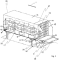
- FIG. 1 showing a three-dimensional, partially sectional view of a system according to the present invention in use with a container positioned in an unloading bay
- FIG. 2 showing a detailed view of a first reel in Fig. 1
- Fig. 3 showing a detailed view of a region of a beginning of a conveyor in Fig. 1
- Fig. 4 showing a three-dimensional view of a compensation system in Fig. 1 seen from below
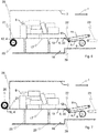
- Fig. 5 showing a sectional view of another embodiment of the system according to the present invention in use with a container positioned in an unloading bay
- Fig. 1 shows a container 3 filled with unit load in form of parcels 5, the container 3 being arranged in an unloading bay 18, in order to be unloaded.
- the container 3 rests on a scaffold-like container support 25 at a certain (height) level above the ground.
- the container 3 could also be supported by a transport vehicle or could be an integrated part of a transport vehicle too.
- a system for enabling an automatic unloading of the parcels 5 a system according the present invention is provided, the system having a mobile part provided with the container 3 and a stationary part provided at the unloading bay 18.
- the system is in a first state.
- the mobile part of the system comprises a first belt 2 with a load section 19 covering a floor 17 of the container 3.
- the load section 19 covers the floor 17 for the most part, with the parcels 5 being arranged in stacks located on the load section 19.
- the stationary part of the system comprises a traction mechanism which is situated on a step 28 of the unloading bay 18 in the embodiment shown in Fig. 1 .
- the traction mechanism serves for pulling out at least part of the load section 19, in order to bring the system from the first state to a second state, thereby unloading the parcels 5.
- the traction mechanism comprises at least one traction means which can be coupled to the first belt 2 by means of at least one first fastening means 6 of the first belt 2 and at least one complementary second fastening means 30 of the traction mechanism.
- the at least one traction means comprises a second belt 7.
- several first fastening means 6 of the first belt 2 and several second fastening means 30 of the second belt 7 are recognisable, with the fastening means 6, 30 preferably being of a hook and loop type.
- first fastening means 6 comprises a kind of swivelling hook 32 and a plate 33 that are attached to the first belt 2.
- the second fastening means 30 comprises an eye 34 attached to the second belt 7. At least part of the eye 34 can be arranged on the plate 33, allowing for engagement of the hook 32 with the eye 34 such that a part of the eye 34 is arranged between the hook 32 and the plate 33.
- the first fastening means 6 comprises a hook 32, which is attached to the first belt 2 and which preferably can be swivelled.
- the second fastening means 30 comprises an eye 34 attached to the second belt 7, allowing for engagement of the hook 32 with the eye 34.
- the first fastening means 6 comprises a magnetic plate 35 attached to the first belt 2.
- the magnetic plate 35 can be made of or may comprise at least one permanent magnet.
- the shape of the cross section of the plate 35 which is shown in Fig. 10c , resembles a hook at a free end of the plate 35.
- the second fastening means 30 comprises a plate 36 made of or comprising at least one ferromagnetic material, allowing for engagement of plates 35, 36 by means of magnetic force.
- the shape of the cross section of the plate 36 which is shown in Fig. 10c , resembles a hook at a free end of the plate 36, with the shape being complementary to the one of the plate 35.
- a form-fit coupling between plates 35, 36 is given.
- both a form-fit coupling and a force-fit coupling of the first belt 2 with the second belt 7 and the traction mechanism, respectively, are realised.
- the first fastening means 6 is constituted by a free end section 37 of the first belt 2 only.
- the second fastening means 30 comprises a clamp 38 for gripping of the free end section 37 between to arms of the clamp 38.
- the traction mechanism comprises a second storage element in the form of a second reel 8 for storage of the second belt 7 by winding up the second belt 7 onto the second reel 8, i.e. the second belt 7 is coupled to the second reel 8.
- the traction mechanism comprises a drive motor 16 for driving the second reel 8 in a certain direction of rotation.
- the system With the first belt 2 being coupled to the second belt 7, the system is brought into a second state, which is illustrated in Fig. 11 , by driving the second reel 8.
- this second state at least a part of the load section 19 is pulled out of the container 3.
- those parcels 5 that were located on this part of the load section 19 in the first state of the system are unloaded from the container 3 now.
- the load section 19 is pulled out of the container 3 along a conveying direction 1, which conveying direction 1 points from a rear wall 26 of the container 3 to a front side 27 of the container 3.
- the front side 27 is situated opposite the rear wall 26.
- the front side 27 is open (doors for closing are not shown for the sake of clarity) and is facing the unloading bay 18, enabling coupling between the mobile and the stationary part of the system.
- At least the load section 19 of the first belt 2 is configured such that the friction between the first belt 2 and the floor 17 is low.
- that side of the first belt 2, which is configured for facing the floor 17 of the container 3 can be made of or can at least comprise a polyester (PET) fabric, in order to realise a small friction coefficient between the first belt 2 and the floor 17.
- PET polyester
- at least the load section 19 of the first belt 2 is either made of or coated (on the side facing the floor 17) with a low-friction material like ultra-high-molecular-weight polyethylene (UHMWPE), which is also known as high-modulus polyethylene (HMPE) or high-performance polyethylene (HPPE).
- UHMWPE ultra-high-molecular-weight polyethylene
- HMPE high-modulus polyethylene
- HPPE high-performance polyethylene
- the traction mechanism comprises a guide roller 39 for guiding the second belt 7 - and of course also the first belt 2 when the system is brought from its first to its second state - from the floor 17 ending on the front side 27 of the container 3 to the second reel 8.
- retraction means are provided for retracting at least the first belt 2 and preferably also the second belt 7.
- the retraction means comprise a retracting section 20 of the first belt 2.
- the retracting section 20 of the first belt 2 is wound around a first reel 4 for storage, i.e. the first reel 4 constitutes a first storage element for the retracting section 20.
- the first reel 4 is arranged in a housing 13 which housing 13 is situated on the floor 17 adjacent to the rear wall 26 of the container 3. Seen in the conveying direction 1 the housing 13 has an inclined shape pointing downwards. This inclination assures that parcels 5 glide off the housing 13 onto the first belt 2 and do not stay on the housing 13. This means that all parcels 5 can be unloaded and no parcel 5 remains in the container 3.
- the retracting section 20 or at least a part of the retracting section 20 is wound off the first reel 4 and is eventually covering the floor 17.
- a length of the retracting section 20 is at least as large as a length of the container 3, in order to ensure that indeed the whole load section 19 can be pulled out of the container 3, with the mentioned lengths being measured along the conveying direction 1. Accordingly, an overall length of the first belt is at least twice as large as the length of the container 3.
- the retraction means further comprise a spring 10.
- the spring 10 is coupled to a hub 29 of the first reel 4 in a known manner, cf. Fig. 2 showing a detailed view of the first reel 4.
- the tensioned spring 10 is used for winding up the retracting section 20 again, thereby pulling the load section 19 back into the container 3 for re-establishing the first state of the system - without the need for an additional motor.
- the second reel 8 may be driven in an opposite rotational direction, opposite to the certain direction of rotation, by means of the motor 16, for example.
- the spring 10 ensures that the retracting section 20 is wound up onto the first reel 4 again and the motor 16 can be used as kind of brake for adjusting the speed of retraction of the belts 2, 7, in order to guarantee a controlled and save retraction.
- additional braking means for that purpose, with the additional braking means preferably being part of the traction mechanism.
- a coupling between the motor 16 and the second reel 8 may be just released, for example, in order to let the spring 10 drive the second reel 8 in the opposite rotational direction while winding up the retracting section 20.
- the second belt 4 can be wound off the second reel 8.
- a belt conveyor is provided.
- the conveyor 11 is arranged relative to the traction mechanism - and vice versa - such that the parcels 5 on the first belt 2 are transferred onto the conveyor 11 while the first belt 2 is pulled out of the container 3.
- a skilled person can find many different arrangements that fulfil this condition.
- the conveyor 11 is positioned above the second reel 8.
- a beginning 22 of the conveyor 11 is arranged adjacent to the front side 27 and essentially on the same level as the floor 17 of the container 3 or at least close to that level. Accordingly, the first belt 2 is pulled under the conveyer 11 and the parcels 5 glide from the first belt 2 onto the conveyor 11 almost immediately after having left the container 3.
- Fig. 9 shows another embodiment, similarly to the embodiment shown in Fig. 5 .
- the conveyor 11 is, however, positioned farther behind the container 3 when viewed in conveying direction 1, with the beginning 22 of the conveyor 11 not being adjacent to the front side 27 of the container 3.
- the resulting distance between the container 3 and the conveyor 11 is spanned by the second belt 7 when the system is in its first state. In its second state said distance can be spanned by the first belt 2 too.
- two guide rollers 39, 39' are used that are arranged at different levels.
- the beginning 22 of the conveyor 11 is arranged adjacent to the higher guide roller 39'. Also this arrangement enables pulling of the first belt 2 under the conveyor 11, in order to let the parcels 5 glide off the first belt 2 onto the conveyor 11.
- Fig. 8 shows another embodiment with the conveyor 11 being arranged behind the second reel 8 viewed in conveying direction.
- the parcels 5 are conveyed on the first belt 2 over a certain distance after having left the container 3.
- the parcels 5 glide from the first belt 2 onto the conveyor 11.
- the conveyor 11 in the embodiments shown in Figs. 1 , 3 , 5 , 6 , 7 and 9 is slightly inclined upwardly seen in conveying direction 1, fostering de-stacking of the parcels 5 in a controlled way and helping preventing parcels 5 from rolling off each other in an uncontrolled way.
- a further conveyor 23, arranged after the conveyor 11 seen in conveying direction 1, can be provided for further transportation of the parcels 5 in a known manner.
- a sliding plate 12 is arranged in a region of the beginning 22 of the conveyor 11.
- said sliding plate 12 bridges a small gap between the container 3 / the floor 17 and the beginning 22 of the conveyor 11.
- the sliding plate 12 bridges a small gap between the highest point 31 of the second reel 8 and the beginning 22 of the conveyor 11.
- the sliding plate 12 bridges a small gap between the higher guide roller 39' and the beginning 22 of the conveyor 11.
- Whether a slide plate 12 is really necessary depends on the size of the parcels 5 in relation to the size of the respective gap. The latter is determined by the diameter of the guide rollers 39, 39' and of rollers deployed in the conveyor 11, respectively. Thus, the system can work also without a sliding plate 12, principally.
- the conveyor 11 conveys the parcels 5 preferably faster than the first belt 2. Hence, a conveying velocity of the conveyor 11 is greater than a conveying velocity of the first belt 2 and its load section 19, respectively, which is pulled out of the container 3. Thereby, the conveying velocities are measured parallel to the conveying direction 1.
- the greater conveying velocity of the conveyor 11 already leads to a singulation of the parcels 5.
- the parcels 5 reach the conveyor 11 they are abruptly accelerated. If the parcels 5 are arranged in stacks with one ore more parcels 5 being placed atop a first parcel 5 lying directly on the first belt 2, the parcels 5 fall off the first parcel 5 due to the abrupt acceleration of the first parcel 5.
- a curtain 14 can be provided as de-stacking means, cf. Figs. 1 and 11 .
- the curtain 14 is held in a curtain holding frame 24 defining the position of the curtain 14, particularly relative to the conveyor 11.
- the curtain 14 is arranged above the conveyor 11, in order to retain parcels 5 that are still placed atop a first parcel 5 lying directly on the conveyor 11.
- lateral walls 15 are provided for preventing parcels 5 from falling off the conveyor 11. These lateral walls 15 are arranged in a tapering way when viewed in the conveying direction 1, allowing for a lateral alignment of the parcels 5 on the conveyor and thus for a reduction of lateral dimensions of following conveying means like the further conveyor 23.
- a compensation system 9 is provided at the unloading bay 18, with the traction mechanism being mounted on the compensation system 9. As can be seen in the detailed view of Fig. 4 the compensation system 9 allows for adjustment of the level (cf. the double arrow in Fig. 4 ) of the traction mechanism, i.e.
- Fig. 4 only shows an example of a compensation system 9 suitable for compensating the offset and/or misorientation.
- a skilled person can find many other different embodiments of suitable compensation systems 9.
- the curtain holding frame 24 with the curtain 14 and the lateral walls 15 are mounted on the compensation system 9. Accordingly, these elements are aligned concurrently with the traction mechanism.
- Figs. 6 and 7 show embodiments with the first reel 4 being positioned outside the container 3, allowing for maximising the available area on the floor 17 and the available space inside the container 3.
- a corresponding opening 21 is provided in the container 3.
- the first reel 2 is arranged below the floor 17, close to the rear wall 26 of the container 3. Accordingly, the opening 21 is disposed in the floor 17, close to the rear wall 26.
- the first reel 2 is arranged in front of the rear wall 26, when viewed in conveying direction 1, and close to the floor 17. Accordingly, the opening 21 is disposed in the rear wall 26, close to the floor 17. In this case, essentially the whole floor 17 can be covered by the load section 19. Hence, the area on the floor 17 and the space inside the container 3, respectively, which can be used for loading of parcels 5, is at the maximum.
- the parcels 5 are unloaded from the container 3 by bringing the system according to the present invention from its first state to its second state. Afterwards, by bringing the system back to its first state, a container 3 is provided which is empty (not illustrated) and ready to be filled again with unit load, wherein the unit load can be arranged on the load section 19. As soon as the fastening means 6, 30 are released the front side 27 of the container 3 can be closed (not illustrated) and the container 3 can be moved away from the unloading bay 18.
Landscapes
- Engineering & Computer Science (AREA)
- Aviation & Aerospace Engineering (AREA)
- Mechanical Engineering (AREA)
- Warehouses Or Storage Devices (AREA)
Description
- The present invention relates to a system for unloading items from a container positioned in an unloading bay, the system comprising a first belt, wherein in a first state of the system a load section of the first belt is configured for covering a floor of the container, enabling arrangement of the items on the load section, the system further comprising a traction mechanism for being provided at the unloading bay, wherein the first belt comprises at least one first fastening means and the traction mechanism comprises at least one second fastening means for coupling the first belt to the traction mechanism, wherein the traction mechanism is configured such that at least a part of the load section of the coupled first belt can be pulled out of the container by means of the traction mechanism, in order to bring the system from the first state to a second state.
- Since several years the parcel service market is growing continuously, which is at least partially driven by increasing numbers of online orders. Usually, parcels or other unit load are transported by means of containers to parcel distribution centres, where the parcels are unloaded manually. The latter process is time consuming and can be critical from the viewpoint of occupational medicine, since heavy items have to be lifted by personnel frequently and non-ergonomically. Device developments for automation of the unloading process are quite complex and expensive so far and hence hardly in use.
- One example for such known device is disclosed by
US 2012/0087770 A1 , relating to a system with a base belt located in a container, on which base belt a plurality of items is arranged. For unloading an apparatus is moved into the container, the apparatus comprising a tensioning mechanism, in order to tension the base belt for enabling passing of a ramp under the base belt. This in turn allows for removing a first item by means of a conveyor, while a stack control curtain is retaining other items. Since the conveyor as well as the stack control curtain have to be moved into the container, very high demands on movement control are made. -
WO 2010/109094 A1 discloses a system according to the preamble ofclaim 1 comprising a conveyor belt for loading and unloading of a vehicle, with the conveyor belt moving between the vehicle and a platform. Thereby, the conveyor belt is pulled by a building-side and vehicle-side pulling means in the form of belts that are connected to the conveyor belt by means of a hook system. The belts are in turn driven by motorised winches situated on the platform and the vehicle. -
US 4749325 A teaches a device for unloading a truck with a bed, employing a slip floor on which items may be arranged. It is possible to pull the slip floor out of the truck with the items being still arranged on the slip floor, in order to unload the truck at an unloading platform. Cables and rings are mounted to the slip floor, enabling coupling with a belt having hooks, in order to pull at the slip floor. Thereby, the belt is operated by a powered winding roll. - Thus, it is the object of the present invention to provide a system for unloading unit load from a container, which overcomes the above mentioned disadvantages. Particularly, it is the object of the present invention to provide a system which has a simple structure and which can easily be implemented with existing containers and at existing parcel distribution centres.
- For solving the above mentioned problems a system for unloading times from a container positioned in an unloading bay is suggested, which system comprises a mobile part for being provided with the container and a stationary part for being provided at the unloading bay. The container can be transported by a transport vehicle or can be integrated into a transport vehicle. Preferably, the unloading bay may be used for loading of items into the container too.
- The structure of the mobile part is very simple, allowing for easy and cheap retrofitting of existing containers. The mobile part comprises a first belt which can be used for covering a floor of the container such that items can be arranged on the first belt. Complementary fastening means of the mobile part and the stationary part allow for coupling of the mobile part with the stationary part, enabling acting of the stationary part on the mobile part. Particularly, the stationary part comprises a traction mechanism which allows pulling of the first belt coupled to the stationary part and the traction mechanism, respectively. Naturally, if the first belt is pulled, also items arranged on the first belt are pulled. Hence, the system according to the present invention can be used for unloading items from the container.
- Therefore, a system for unloading items from a container positioned in an unloading bay is provided, the system comprising a first belt, wherein in a first state of the system a load section of the first belt is configured for covering a floor of the container, enabling arrangement of the items on the load section, wherein according to the present invention it is provided that the system comprises a traction mechanism for being provided at the unloading bay, wherein the first belt comprises at least one first fastening means and the traction mechanism comprises at least one second fastening means for coupling the first belt to the traction mechanism, wherein the traction mechanism is configured such that at least a part of the load section of the coupled first belt can be pulled out of the container by means of the traction mechanism, in order to bring the system from the first state to a second state. This means that in the second state the first belt is configured for being at least partly pulled out of the container by means of the traction mechanism.
- Preferably, at least one traction means, like a strap, a belt or a tape, is provided which is to be coupled with the first belt. The at least one traction means can be stored using a storage element - which is referred to as "second storage element" in the following -, in order to save space at the unloading bay. Moreover, also at least part of the coupled load section, which is pulled by the at least one traction means, can be stored in the second storage element. An example for such a second storage element would be a box in which the at least one traction means and at least part of the load section can be stored in a folded way. Another example for such a second storage element would be a reel onto which the at least one traction means and at least part of the load section can be wound. Correspondingly, in a preferred embodiment of the system according to the present invention it is provided that the traction mechanism comprises at least one traction means, a second storage element for storage of the at least one traction means and at least a part of the load section, the traction mechanism preferably further comprising a motor, particularly for driving the second storage element.
- Even though it is conceivable to drive the at least one traction means manually, a motor will be deployed usually, for speeding up the whole process, with the motor preferably driving an element of the traction mechanism, in order to act on the at least one traction means. In case the second storage element is of a reel type, the motor may drive the second storage element for acting on the at least one traction means.
- Accordingly, in a preferred embodiment of the system according to the present invention it is provided that the at least one traction means comprises a second belt. Moreover, in a preferred embodiment of the system according to the present invention it is provided that the second storage element comprises a second reel.
- In order to bring the system from the second state back to the first state, it is provided in a preferred embodiment of the system according to the present invention that retraction means are provided for retracting at least the first belt. Preferably, also the at least one traction means, which is coupled to the first belt, particularly the coupled second belt, can be retracted by the retraction means. An example for such retraction means would be a motor acting on the first belt. Another example for such retraction means would be means enabling a manual retraction by a user.
- Preferably, the retraction means are part of the mobile part of the system. In order to allow for a particularly simple structure of such retraction means, it is provided in a preferred embodiment of the system according to the present invention that the retraction means comprise a retracting section of the first belt and a first storage element, which retracting section is stored by means of the first storage element in the first state of the system, wherein at least a part of the retracting section is configured for covering the floor of the container in the second state of the system.
- In order to guarantee that the whole load section can be pulled out of the container, it is provided in a preferred embodiment of the system according to the present invention that a length of the retracting section is at least as large as a length of the container and an overall length of the first belt is at least twice as large as the length of the container. Said lengths are measured along a conveying direction pointing from a rear wall of the container to a front side of the container, with the front side facing the unloading bay and being open for unloading of the items.
- In order to achieve particularly simple retraction means without a motor needing an energy supply, it is provided in a preferred embodiment of the system according to the present invention that the retraction means comprise a spring which is configured such that the spring is tensioned when the system is brought from the first to the second state and by retracting at least the first belt the tension is released. Preferably, also the at least one traction means, which is coupled to the first belt, particularly the coupled second belt, can be retracted by releasing the tension of the spring.
- An example for the first storage element would be a box in which the retracting section of the first belt can be stored in a folded way. Another example for the first storage element would be a reel - in the following referred to as "first reel" - onto which the retracting section of the first belt can be wound. The latter example can be realised in a particularly simple way. Furthermore, the first reel can be easily driven for retracting at least the retracting section of the first belt. For driving the first reel a motor could be provided, for example. However, the first reel is ideally suited for using the spring as driving means, with the spring coupled to a hub of the first reel in a known manner, for example. Accordingly, in a preferred embodiment of the system according to the present invention it is provided that the first storage element comprises a first reel.
- There are several options where to mount the first storage element. For example, the first storage element can be arranged inside the container. This has the advantage that the first storage element can be protected from external effects like the weather. Moreover, the first storage element cannot interfere with any transportation means, e.g. transport vehicles, that engage with the exterior of the container. Accordingly, in a preferred embodiment of the system according to the present invention it is provided that the first storage element is configured for being situated within the container, wherein the first storage element has a housing with an inclined shape, in order to let items glide off the housing onto the first belt. Hence, it can be ensured that in the unloading process no items remain within the container.
- Alternatively, the first storage element can be arranged outside the container. This provides for maximising the available area on the container floor and the available space in the container, respectively. However, the container has to be adapted for allowing passing of the first belt from outside into the container. Accordingly, in a preferred embodiment of the system according to the present invention it is provided that the system comprises the container. Moreover, in a preferred embodiment of the system according to the present invention it is provided that the first storage element is situated outside the container, with an opening being provided in the container and allowing for passage of the first belt.
- In order to transport those items that originally are arranged on the load section not only out of the container, but also away from the container, it is provided in the system according to the present invention that the system comprises a conveyor for being provided at the unloading bay, wherein the conveyor is arranged relative to the traction mechanism such that items arranged on the load section are transferred along a conveying direction onto the conveyor while the first belt is pulled by the traction mechanism.
- In order to effect a singulation of the items, it is provided in a preferred embodiment of the system according to the present invention that the conveyor is configured such that a conveying velocity of the conveyor is greater than a conveying velocity of the load section while the first belt is pulled by the traction mechanism. Hence, when the items reach the conveyor they are abruptly accelerated. If the items are arranged in stacks with one ore more items being placed atop a first item lying directly on the first belt, the items fall off the first item due to the abrupt acceleration of the first item.
- Hence, a three-dimensional item arrangement on the first belt can be reduced to an essentially two-dimensional item arrangement on the conveyor.
- In a preferred embodiment of the system according to the present invention it is provided that a sliding plate is provided for facilitating the transfer of items onto the conveyor, wherein the sliding plate is arranged in a region of a beginning of the conveyor when viewed in conveying direction. For example, the sliding plate can be used to bridge a gap before the beginning of the conveyor when viewed in conveying direction.
- In order to improve the singulation, it is provided in a preferred embodiment of the system according to the present invention that a de-stacking means, preferably a curtain is provided, wherein the de-stacking means is arranged above the conveyor for retaining items placed atop a first item which first item is arranged directly on the conveyor. Generally, the de-stacking means can be a flexible or rigid barrier, preferably arranged above the conveyor.
- In a preferred embodiment of the system according to the present invention it is provided that lateral walls are provided for preventing items from falling off the conveyor, which lateral walls are preferably arranged in a tapering way when viewed in the conveying direction. The tapering arrangement allows for a lateral alignment of the items on the conveyor and thus for a reduction of lateral dimensions of following conveying means like a further conveyor.
- In order to further prevent items rolling off a stack of items in an uncontrolled way, it is provided in a preferred embodiment of the system according to the present invention that the conveyor is upwardly inclined when viewed in conveying direction.
- In a preferred embodiment of the system according to the present invention it is provided that the at least one first fastening means and the at least one second fastening means are configured such that the coupling of the first belt with the traction mechanism is a form-fit coupling and/or a force-fit coupling. For example, the fastening means can be of the hook and loop type. Alternatively or additionally, the fastening means could be at least partially magnetic for employing magnetic interaction for coupling. The system according to the present invention is provided with a compensation system, with the traction mechanism being mounted on the compensation system for compensating an offset and/or a misorientation of the traction mechanism to the first belt, in order to enable coupling of the first belt with the traction mechanism. By means of the compensation system the height level and the orientation of the traction mechanism can be adjusted in a known manner.
- The invention will be explained in closer detail by reference to preferred embodiments, with
Fig. 1 showing a three-dimensional, partially sectional view of a system according to the present invention in use with a container positioned in an unloading bayFig. 2 showing a detailed view of a first reel inFig. 1 Fig. 3 showing a detailed view of a region of a beginning of a conveyor inFig. 1 Fig. 4 showing a three-dimensional view of a compensation system inFig. 1 seen from belowFig. 5 showing a sectional view of another embodiment of the system according to the present invention in use with a container positioned in an unloading bay - Fig. 6
- showing a sectional view of further embodiment of the system according to the present invention with a container positioned in an unloading bay
- Fig. 7
- showing a sectional view of further embodiment of the system according to the present invention with a container positioned in an unloading bay
- Fig. 8
- showing a sectional view of further embodiment of the system according to the present invention in use with a container positioned in an unloading bay
- Fig. 9
- showing a sectional view of another embodiment of the system according to the present invention in use with a container positioned in an unloading bay
- Figs. 10a-d
- schematically illustrating several variants of first and second fastening means by sectional views
- Fig. 11
- showing the embodiment of
Fig. 1 in a second state -
Fig. 1 shows acontainer 3 filled with unit load in form ofparcels 5, thecontainer 3 being arranged in an unloadingbay 18, in order to be unloaded. In the shown example thecontainer 3 rests on a scaffold-like container support 25 at a certain (height) level above the ground. Principally, thecontainer 3 could also be supported by a transport vehicle or could be an integrated part of a transport vehicle too. - For enabling an automatic unloading of the parcels 5 a system according the present invention is provided, the system having a mobile part provided with the
container 3 and a stationary part provided at the unloadingbay 18. - In
Fig. 1 the system is in a first state. Thereby, the mobile part of the system comprises afirst belt 2 with a load section 19 covering afloor 17 of thecontainer 3. In the shown embodiments the load section 19 covers thefloor 17 for the most part, with theparcels 5 being arranged in stacks located on the load section 19. - The stationary part of the system comprises a traction mechanism which is situated on a
step 28 of the unloadingbay 18 in the embodiment shown inFig. 1 . The traction mechanism serves for pulling out at least part of the load section 19, in order to bring the system from the first state to a second state, thereby unloading theparcels 5. Accordingly, the traction mechanism comprises at least one traction means which can be coupled to thefirst belt 2 by means of at least one first fastening means 6 of thefirst belt 2 and at least one complementary second fastening means 30 of the traction mechanism. - In the shown embodiments the at least one traction means comprises a
second belt 7. In the detailed view ofFig. 3 several first fastening means 6 of thefirst belt 2 and several second fastening means 30 of thesecond belt 7 are recognisable, with the fastening means 6, 30 preferably being of a hook and loop type. - However, a plurality of other variants for complementary first and second fastening means 6, 30 is conceivable, as is exemplified by
Figs. 10a to 10d . InFig. 10a the first fastening means 6 comprises a kind of swivelling hook 32 and a plate 33 that are attached to thefirst belt 2. The second fastening means 30 comprises an eye 34 attached to thesecond belt 7. At least part of the eye 34 can be arranged on the plate 33, allowing for engagement of the hook 32 with the eye 34 such that a part of the eye 34 is arranged between the hook 32 and the plate 33. Hence, a form-fit coupling of thefirst belt 2 with thesecond belt 7 and the traction mechanism, respectively, is realised. - Similarly, in
Fig. 10b the first fastening means 6 comprises a hook 32, which is attached to thefirst belt 2 and which preferably can be swivelled. The second fastening means 30 comprises an eye 34 attached to thesecond belt 7, allowing for engagement of the hook 32 with the eye 34. Hence, a form-fit coupling of thefirst belt 2 with thesecond belt 7 and the traction mechanism, respectively, is realised. - In
Fig. 10c the first fastening means 6 comprises a magnetic plate 35 attached to thefirst belt 2. For example, the magnetic plate 35 can be made of or may comprise at least one permanent magnet. Moreover, the shape of the cross section of the plate 35, which is shown inFig. 10c , resembles a hook at a free end of the plate 35. The second fastening means 30 comprises a plate 36 made of or comprising at least one ferromagnetic material, allowing for engagement of plates 35, 36 by means of magnetic force. Moreover, the shape of the cross section of the plate 36, which is shown inFig. 10c , resembles a hook at a free end of the plate 36, with the shape being complementary to the one of the plate 35. Thus, also a form-fit coupling between plates 35, 36 is given. Hence, both a form-fit coupling and a force-fit coupling of thefirst belt 2 with thesecond belt 7 and the traction mechanism, respectively, are realised. - In
Fig. 10d the first fastening means 6 is constituted by a free end section 37 of thefirst belt 2 only. The second fastening means 30 comprises a clamp 38 for gripping of the free end section 37 between to arms of the clamp 38. Hence, a force-fit coupling of thefirst belt 2 with thesecond belt 7 and the traction mechanism, respectively, is realised. - Furthermore, the traction mechanism comprises a second storage element in the form of a
second reel 8 for storage of thesecond belt 7 by winding up thesecond belt 7 onto thesecond reel 8, i.e. thesecond belt 7 is coupled to thesecond reel 8. For doing so, the traction mechanism comprises adrive motor 16 for driving thesecond reel 8 in a certain direction of rotation. - With the
first belt 2 being coupled to thesecond belt 7, the system is brought into a second state, which is illustrated inFig. 11 , by driving thesecond reel 8. In this second state at least a part of the load section 19 is pulled out of thecontainer 3. Correspondingly, thoseparcels 5 that were located on this part of the load section 19 in the first state of the system are unloaded from thecontainer 3 now. - Due to the coupling between the
belts first belt 2 can be wound around thesecond reel 8 for storage. This can particularly be the case if at least the whole load section 19 is pulled out of thecontainer 3, in order to ensure that indeed allparcels 5 are transferred out of thecontainer 3. - The load section 19 is pulled out of the
container 3 along a conveyingdirection 1, which conveyingdirection 1 points from arear wall 26 of thecontainer 3 to afront side 27 of thecontainer 3. Thefront side 27 is situated opposite therear wall 26. In the shown embodiments thefront side 27 is open (doors for closing are not shown for the sake of clarity) and is facing the unloadingbay 18, enabling coupling between the mobile and the stationary part of the system. - For facilitating pulling of the load section 19 at least the load section 19 of the
first belt 2 is configured such that the friction between thefirst belt 2 and thefloor 17 is low. For example, that side of thefirst belt 2, which is configured for facing thefloor 17 of thecontainer 3, can be made of or can at least comprise a polyester (PET) fabric, in order to realise a small friction coefficient between thefirst belt 2 and thefloor 17. Preferably, at least the load section 19 of thefirst belt 2 is either made of or coated (on the side facing the floor 17) with a low-friction material like ultra-high-molecular-weight polyethylene (UHMWPE), which is also known as high-modulus polyethylene (HMPE) or high-performance polyethylene (HPPE). - In
Fig. 3 it is also very well recognisable that in the embodiment shown inFig. 1 the traction mechanism comprises aguide roller 39 for guiding the second belt 7 - and of course also thefirst belt 2 when the system is brought from its first to its second state - from thefloor 17 ending on thefront side 27 of thecontainer 3 to thesecond reel 8. - In order to bring the system back to its first state after all
parcels 5 are unloaded from thecontainer 3, retraction means are provided for retracting at least thefirst belt 2 and preferably also thesecond belt 7. In the shown embodiments the retraction means comprise a retractingsection 20 of thefirst belt 2. In the first state of the system, the retractingsection 20 of thefirst belt 2 is wound around afirst reel 4 for storage, i.e. thefirst reel 4 constitutes a first storage element for the retractingsection 20. - In the embodiment shown in
Fig. 1 thefirst reel 4 is arranged in ahousing 13 whichhousing 13 is situated on thefloor 17 adjacent to therear wall 26 of thecontainer 3. Seen in the conveyingdirection 1 thehousing 13 has an inclined shape pointing downwards. This inclination assures thatparcels 5 glide off thehousing 13 onto thefirst belt 2 and do not stay on thehousing 13. This means that allparcels 5 can be unloaded and noparcel 5 remains in thecontainer 3. - While the load section 19 is pulled out of the
container 3 the retractingsection 20 or at least a part of the retractingsection 20 is wound off thefirst reel 4 and is eventually covering thefloor 17. - Preferably, a length of the retracting
section 20 is at least as large as a length of thecontainer 3, in order to ensure that indeed the whole load section 19 can be pulled out of thecontainer 3, with the mentioned lengths being measured along the conveyingdirection 1. Accordingly, an overall length of the first belt is at least twice as large as the length of thecontainer 3. - The retraction means further comprise a
spring 10. In the unwinding process thefirst reel 4 is rotated, which rotation causes tensioning of thespring 10. Thespring 10 is coupled to ahub 29 of thefirst reel 4 in a known manner, cf.Fig. 2 showing a detailed view of thefirst reel 4. - The tensioned
spring 10 is used for winding up the retractingsection 20 again, thereby pulling the load section 19 back into thecontainer 3 for re-establishing the first state of the system - without the need for an additional motor. After theparcels 5 are unloaded and conveyed away from thesecond belt 7, thesecond reel 8 may be driven in an opposite rotational direction, opposite to the certain direction of rotation, by means of themotor 16, for example. Thereby, thespring 10 ensures that the retractingsection 20 is wound up onto thefirst reel 4 again and themotor 16 can be used as kind of brake for adjusting the speed of retraction of thebelts - Alternatively, a coupling between the
motor 16 and thesecond reel 8 may be just released, for example, in order to let thespring 10 drive thesecond reel 8 in the opposite rotational direction while winding up the retractingsection 20. Finally, also thesecond belt 4 can be wound off thesecond reel 8. - In order to convey the
parcels 5 not only out of, but also away from the
container 3, aconveyor 11, a belt conveyor is provided. Theconveyor 11 is arranged relative to the traction mechanism - and vice versa - such that theparcels 5 on thefirst belt 2 are transferred onto theconveyor 11 while thefirst belt 2 is pulled out of thecontainer 3. A skilled person can find many different arrangements that fulfil this condition. In the embodiments shown inFigs. 1 ,3 ,5 ,6, and 7 theconveyor 11 is positioned above thesecond reel 8. Viewed in conveying direction 1 a beginning 22 of theconveyor 11 is arranged adjacent to thefront side 27 and essentially on the same level as thefloor 17 of thecontainer 3 or at least close to that level. Accordingly, thefirst belt 2 is pulled under theconveyer 11 and theparcels 5 glide from thefirst belt 2 onto theconveyor 11 almost immediately after having left thecontainer 3. -
Fig. 9 shows another embodiment, similarly to the embodiment shown inFig. 5 . InFig. 9 theconveyor 11 is, however, positioned farther behind thecontainer 3 when viewed in conveyingdirection 1, with the beginning 22 of theconveyor 11 not being adjacent to thefront side 27 of thecontainer 3. The resulting distance between thecontainer 3 and theconveyor 11 is spanned by thesecond belt 7 when the system is in its first state. In its second state said distance can be spanned by thefirst belt 2 too. In order to guide thebelts second reel 8, twoguide rollers 39, 39' are used that are arranged at different levels. The beginning 22 of theconveyor 11 is arranged adjacent to the higher guide roller 39'. Also this arrangement enables pulling of thefirst belt 2 under theconveyor 11, in order to let theparcels 5 glide off thefirst belt 2 onto theconveyor 11. -
Fig. 8 shows another embodiment with theconveyor 11 being arranged behind thesecond reel 8 viewed in conveying direction. In this case theparcels 5 are conveyed on thefirst belt 2 over a certain distance after having left thecontainer 3. Just when the winding up of thefirst belt 2 onto thesecond reel 8 is started theparcels 5 glide from thefirst belt 2 onto theconveyor 11. - In the embodiment shown in
Fig. 8 this happens when thefirst belt 2 contacts thesecond reel 8 in a region around ahighest point 31 of thesecond reel 8 above the ground of thestep 28 of the unloadingbay 18, where thesecond reel 8 is positioned. Since the level of thehighest point 31 of thesecond reel 8 is higher than the level of thefloor 17 of thecontainer 3, theparcels 5 are transported slightly upwardly between thefront side 27 of thecontainer 3 and thesecond reel 8 and theconveyor 11, respectively. This inclination fosters de-stacking of theparcels 5 in a controlled way and helps preventingparcels 5 from rolling off each other in an uncontrolled way. - Analogously, the
conveyor 11 in the embodiments shown inFigs. 1 ,3 ,5 ,6 ,7 and9 is slightly inclined upwardly seen in conveyingdirection 1, fostering de-stacking of theparcels 5 in a controlled way and helping preventingparcels 5 from rolling off each other in an uncontrolled way. - As can be seen in
Figs. 1 ,3 ,5 ,6 ,7 and9 afurther conveyor 23, arranged after theconveyor 11 seen in conveyingdirection 1, can be provided for further transportation of theparcels 5 in a known manner. - In order to facilitate the transfer of the
parcels 5 from thefirst belt 2 onto theconveyor 11, a slidingplate 12 is arranged in a region of the beginning 22 of theconveyor 11. In the embodiments shown inFigs. 1 ,3 ,5 ,6, and 7 said slidingplate 12 bridges a small gap between thecontainer 3 / thefloor 17 and the beginning 22 of theconveyor 11. In the embodiment shown inFig. 8 the slidingplate 12 bridges a small gap between thehighest point 31 of thesecond reel 8 and the beginning 22 of theconveyor 11. In the embodiment shown inFig. 9 the slidingplate 12 bridges a small gap between the higher guide roller 39' and the beginning 22 of theconveyor 11. Hence, in each shown embodiment the slidingplate 12 preventsparcels 5 from getting caught in the respective gap. Whether aslide plate 12 is really necessary depends on the size of theparcels 5 in relation to the size of the respective gap. The latter is determined by the diameter of theguide rollers 39, 39' and of rollers deployed in theconveyor 11, respectively. Thus, the system can work also without a slidingplate 12, principally. - In each shown embodiment the
conveyor 11 conveys theparcels 5 preferably faster than thefirst belt 2. Hence, a conveying velocity of theconveyor 11 is greater than a conveying velocity of thefirst belt 2 and its load section 19, respectively, which is pulled out of thecontainer 3. Thereby, the conveying velocities are measured parallel to the conveyingdirection 1. - The greater conveying velocity of the
conveyor 11 already leads to a singulation of theparcels 5. When theparcels 5 reach theconveyor 11 they are abruptly accelerated. If theparcels 5 are arranged in stacks with one oremore parcels 5 being placed atop afirst parcel 5 lying directly on thefirst belt 2, theparcels 5 fall off thefirst parcel 5 due to the abrupt acceleration of thefirst parcel 5. - For improving the singulation, a
curtain 14 can be provided as de-stacking means, cf.Figs. 1 and11 . Thecurtain 14 is held in acurtain holding frame 24 defining the position of thecurtain 14, particularly relative to theconveyor 11. Thecurtain 14 is arranged above theconveyor 11, in order to retainparcels 5 that are still placed atop afirst parcel 5 lying directly on theconveyor 11. - Hence, a three-dimensional parcel arrangement on the
first belt 2 is reduced to an essentially two-dimensional parcel arrangement on theconveyor 11. - In the embodiment shown in
Fig. 1 lateral walls 15 are provided for preventingparcels 5 from falling off theconveyor 11. Theselateral walls 15 are arranged in a tapering way when viewed in the conveyingdirection 1, allowing for a lateral alignment of theparcels 5 on the conveyor and thus for a reduction of lateral dimensions of following conveying means like thefurther conveyor 23. - In order to enable coupling between the
first belt 2 and thesecond belt 7, the position of thefirst belt 2 and thecontainer 3, respectively, has to be aligned with the position of thesecond belt 7 and the traction mechanism, respectively. If thecontainer 3 is (or cannot be) positioned sufficiently properly, leaving a certain offset between thefirst belt 2 and the traction mechanism, the position of the traction mechanism has to be adjusted, in order to compensate for the offset and/or misorientation. Hence, acompensation system 9 is provided at the unloadingbay 18, with the traction mechanism being mounted on thecompensation system 9. As can be seen in the detailed view ofFig. 4 thecompensation system 9 allows for adjustment of the level (cf. the double arrow inFig. 4 ) of the traction mechanism, i.e. of the second belt, thesecond reel 8 and thedrive motor 16. Furthermore, the traction mechanism can be turned about three rotational axes (vgl. the three curved arrows inFig. 4 ), in order to account for a misorientation. Hence, the traction mechanism and thefirst belt 2 can be perfectly aligned by means of thecompensation system 9. It has to be emphasised thatFig. 4 only shows an example of acompensation system 9 suitable for compensating the offset and/or misorientation. A skilled person can find many other different embodiments ofsuitable compensation systems 9. - In the embodiment shown in
Fig. 4 also thecurtain holding frame 24 with thecurtain 14 and thelateral walls 15 are mounted on thecompensation system 9. Accordingly, these elements are aligned concurrently with the traction mechanism. - As explained above, in the embodiment shown in
Fig. 1 thefirst reel 4 is arranged inside thecontainer 3. The same holds for the embodiments shown inFigs. 5 and8 . However, the present invention is not limited to those cases.Figs. 6 and 7 show embodiments with thefirst reel 4 being positioned outside thecontainer 3, allowing for maximising the available area on thefloor 17 and the available space inside thecontainer 3. In order to allow for passing thefirst belt 2 from thefirst reel 2, i.e. from outside, into thecontainer 3, acorresponding opening 21 is provided in thecontainer 3. - In the embodiment shown in
Fig. 6 thefirst reel 2 is arranged below thefloor 17, close to therear wall 26 of thecontainer 3. Accordingly, theopening 21 is disposed in thefloor 17, close to therear wall 26. - In the embodiment shown in
Fig. 7 thefirst reel 2 is arranged in front of therear wall 26, when viewed in conveyingdirection 1, and close to thefloor 17. Accordingly, theopening 21 is disposed in therear wall 26, close to thefloor 17. In this case, essentially thewhole floor 17 can be covered by the load section 19. Hence, the area on thefloor 17 and the space inside thecontainer 3, respectively, which can be used for loading ofparcels 5, is at the maximum. - As detailed above the
parcels 5 are unloaded from thecontainer 3 by bringing the system according to the present invention from its first state to its second state. Afterwards, by bringing the system back to its first state, acontainer 3 is provided which is empty (not illustrated) and ready to be filled again with unit load, wherein the unit load can be arranged on the load section 19. As soon as the fastening means 6, 30 are released thefront side 27 of thecontainer 3 can be closed (not illustrated) and thecontainer 3 can be moved away from the unloadingbay 18. -
- 1
- Conveying direction
- 2
- First belt
- 3
- Container
- 4
- First reel
- 5
- Parcel
- 6
- First fastening means
- 7
- Second belt
- 8
- Second reel
- 9
- Compensation system
- 10
- Spring
- 11
- Conveyor
- 12
- Sliding plate
- 13
- Housing of first reel
- 14
- Curtain
- 15
- Lateral wall
- 16
- Drive motor for the second reel
- 17
- Floor of the container
- 18
- Unloading bay
- 19
- Load section of the first belt
- 20
- Retracting section of the first belt
- 21
- Opening for the first belt
- 22
- Beginning of the conveyor
- 23
- Further conveyor
- 24
- Curtain holding frame
- 25
- Container support
- 26
- Rear wall of the container
- 27
- Front side of the container
- 28
- Step of the unloading bay
- 29
- Hub of the first reel
- 30
- Second fastening means
- 31
- Highest point of the second reel
- 32
- Hook
- 33
- Plate
- 34
- Eye
- 35
- Magnetic plate
- 36
- Ferromagnetic plate
- 37
- Free end section of the first belt
- 38
- Clamp
- 39, 39'
- Guide roller
Claims (14)
- System for unloading items (5) from a container (3) positioned in an unloading bay (18), the system comprising a first belt (2), wherein in a first state of the system a load section (19) of the first belt (2) is configured for covering a floor (17) of the container (3), enabling arrangement of the items (5) on the load section (19), the system further comprising a traction mechanism (7, 8, 16) for being provided at the unloading bay (18), wherein the first belt (2) comprises at least one first fastening means (6) and the traction mechanism (7, 8, 16) comprises at least one second fastening means (30) for coupling the first belt (2) to the traction mechanism (7, 8, 16), wherein the traction mechanism (7, 8, 16) is configured such that at least a part of the load section (19) of the coupled first belt (2) can be pulled out of the container (3) by means of the traction mechanism (7, 8, 16), in order to bring the system from the first state to a second state, characterised in that the system comprises a conveyor (11) for being provided at the unloading bay (18), wherein the conveyor (11) is arranged relative to the traction mechanism (7, 8, 16) such that items (5) arranged on the load section (19) are transferred along a conveying direction (1) onto the conveyor (11) while the first belt (2) is pulled by the traction mechanism (7, 8, 16), and in that a compensation system (9) is provided, with the traction mechanism (7, 8, 16) being mounted on the compensation system (9) for compensating an offset and/or a misorientation of the traction mechanism (7, 8, 16) to the first belt (2), in order to enable coupling of the first belt (2) with the traction mechanism (7, 8, 16), wherein the traction mechanism (7, 8, 16) can be turned about three rotational axes.
- System according to claim 1, characterised in that the traction mechanism comprises at least one traction means (7), a second storage element (8) for storage of the at least one traction means (7) and at least a part of the load section (19), the traction mechanism preferably further comprising a motor (16), particularly for driving the second storage element (8).
- System according to claim 2, characterised in that the at least one traction means comprises a second belt (7).
- System according to any one of claims 2 to 3, characterised in that the second storage element comprises a second reel (8).
- System according to any one of claims 1 to 4, characterised in that retraction means (20, 4, 10) are provided for retracting at least the first belt (2), in order to bring the system from the second state back to the first state.
- System according to claim 5, characterised in that the retraction means comprise a retracting section (20) of the first belt (2) and a first storage element (4), which retracting section (20) is stored by means of the first storage element (4) in the first state of the system, wherein at least a part of the retracting section (20) is configured for covering the floor (17) of the container (3) in the second state of the system.
- System according to claim 6, characterised in that a length of the retracting section (20) is at least as large as a length of the container (3) and an overall length of the first belt (2) is at least twice as large as the length of the container (3).
- System according to any one of claims 5 to 7, characterised in that the retraction means comprise a spring (10) which is configured such that the spring (10) is tensioned when the system is brought from the first to the second state and by retracting at least the first belt (2) the tension is released.
- System according to any one of claims 6 to 8, characterised in that the first storage element comprises a first reel (4).
- System according to any one of claims 6 to 9, characterised in that the first storage element (4) is configured for being situated within the container (3), wherein the first storage element (4) has a housing (13) with an inclined shape, in order to let items (5) glide off the housing (13) onto the first belt (2).
- System according to any one of claims 1 to 10, characterised in that the system comprises the container (3).
- System according to claim 11, characterised in that the first storage element (4) is situated outside the container (3), with an opening (21) being provided in the container (3) and allowing for passage of the first belt (2).
- System according to any one of claims 1 to 12, characterised in that a sliding plate (12) is provided for facilitating the transfer of items (5) onto the conveyor (11), wherein the sliding plate (12) is arranged in a region of a beginning (22) of the conveyor (11) when viewed in conveying direction (1).
- System according to any one of claims 1 to 13, characterised in that the conveyor (11) is configured such that a conveying velocity of the conveyor (11) is greater than a conveying velocity of the load section (19) while the first belt (2) is pulled by the traction mechanism (7, 8, 16).
Priority Applications (5)
| Application Number | Priority Date | Filing Date | Title |
|---|---|---|---|
| EP15156347.5A EP3061648B1 (en) | 2015-02-24 | 2015-02-24 | Unloading system for unit load |
| TR2018/07853T TR201807853T4 (en) | 2015-02-24 | 2015-02-24 | Unloading system for unit load. |
| ES15156347.5T ES2676064T3 (en) | 2015-02-24 | 2015-02-24 | Unloading system for charging unit |
| DK15156347.5T DK3061648T3 (en) | 2015-02-24 | 2015-02-24 | Unit load unloading system |
| PL15156347T PL3061648T3 (en) | 2015-02-24 | 2015-02-24 | Unloading system for unit load |
Applications Claiming Priority (1)
| Application Number | Priority Date | Filing Date | Title |
|---|---|---|---|
| EP15156347.5A EP3061648B1 (en) | 2015-02-24 | 2015-02-24 | Unloading system for unit load |
Publications (2)
| Publication Number | Publication Date |
|---|---|
| EP3061648A1 EP3061648A1 (en) | 2016-08-31 |
| EP3061648B1 true EP3061648B1 (en) | 2018-04-18 |
Family
ID=52595104
Family Applications (1)
| Application Number | Title | Priority Date | Filing Date |
|---|---|---|---|
| EP15156347.5A Active EP3061648B1 (en) | 2015-02-24 | 2015-02-24 | Unloading system for unit load |
Country Status (5)
| Country | Link |
|---|---|
| EP (1) | EP3061648B1 (en) |
| DK (1) | DK3061648T3 (en) |
| ES (1) | ES2676064T3 (en) |
| PL (1) | PL3061648T3 (en) |
| TR (1) | TR201807853T4 (en) |
Cited By (1)
| Publication number | Priority date | Publication date | Assignee | Title |
|---|---|---|---|---|
| EP4071094A1 (en) | 2021-04-06 | 2022-10-12 | PHS Logistiktechnik GmbH | Load carrier for loading and unloading a container |
Families Citing this family (2)
| Publication number | Priority date | Publication date | Assignee | Title |
|---|---|---|---|---|
| CN105947715B (en) * | 2016-06-23 | 2018-03-09 | 福建工程学院 | A kind of New semi automatic portable vehicle easing gear |
| WO2023214265A1 (en) * | 2022-05-02 | 2023-11-09 | Signode Netherlands Bv | Item supporter for shipping and methods of use |
Citations (1)
| Publication number | Priority date | Publication date | Assignee | Title |
|---|---|---|---|---|
| EP2338727A1 (en) * | 2009-12-24 | 2011-06-29 | Gérard Grosse | Truck with a buil in conveyor belt |
Family Cites Families (9)
| Publication number | Priority date | Publication date | Assignee | Title |
|---|---|---|---|---|
| GB885879A (en) * | 1958-06-30 | 1961-12-28 | Haller Gmbh Fahrzeugbau | Improvements in refuse or like trucks |
| IT1033589B (en) * | 1974-01-15 | 1979-08-10 | Ditta H | SYSTEM OF EQUIPMENT FOR THE PREPARATION, LOADING AND UNLOADING OF GOODS FROM MEANS OF TRANSPORT |
| DE8427341U1 (en) * | 1984-09-17 | 1984-12-20 | Schüchen, Robert Erich, 5231 Kroppach | Vehicle for transporting loads |
| US4749325A (en) * | 1986-09-11 | 1988-06-07 | Rolflor Industries, Inc. | Method and apparatus for loading trucks |
| US4892456A (en) * | 1988-02-04 | 1990-01-09 | Rolflor Industries, Inc. | Unloading system for freight containers |
| US5902090A (en) * | 1996-05-24 | 1999-05-11 | Eta Industries | Cargo handling truck bed |
| FR2821806B1 (en) * | 2001-03-09 | 2003-12-19 | Thierry Gachet | QUICK LOADING AND UNLOADING DEVICE FOR RAIL ROAD TRANSPORT WITH CARPET ASSISTED BY HYDRAULIC CYLINDERS |
| FR2943644A1 (en) * | 2009-03-24 | 2010-10-01 | Thierry Gachet | SLIDING MOBILE LOAD MAT FOR DEVICE FOR LOADING AND UNLOADING VEHICLES. |
| US8651794B2 (en) | 2010-04-22 | 2014-02-18 | Siemens Industry, Inc. | Automated bed-loaded container unloader and method |
-
2015
- 2015-02-24 EP EP15156347.5A patent/EP3061648B1/en active Active
- 2015-02-24 TR TR2018/07853T patent/TR201807853T4/en unknown
- 2015-02-24 DK DK15156347.5T patent/DK3061648T3/en active
- 2015-02-24 ES ES15156347.5T patent/ES2676064T3/en active Active
- 2015-02-24 PL PL15156347T patent/PL3061648T3/en unknown
Patent Citations (1)
| Publication number | Priority date | Publication date | Assignee | Title |
|---|---|---|---|---|
| EP2338727A1 (en) * | 2009-12-24 | 2011-06-29 | Gérard Grosse | Truck with a buil in conveyor belt |
Cited By (3)
| Publication number | Priority date | Publication date | Assignee | Title |
|---|---|---|---|---|
| EP4071094A1 (en) | 2021-04-06 | 2022-10-12 | PHS Logistiktechnik GmbH | Load carrier for loading and unloading a container |
| WO2022214461A1 (en) | 2021-04-06 | 2022-10-13 | Phs Logistiktechnik Gmbh | Load carrier for loading and unloading a container |
| US12006154B2 (en) | 2021-04-06 | 2024-06-11 | Phs Logistiktechnik Gmbh | Load carrier for loading and unloading a container |
Also Published As
| Publication number | Publication date |
|---|---|
| PL3061648T3 (en) | 2018-09-28 |
| TR201807853T4 (en) | 2018-06-21 |
| ES2676064T3 (en) | 2018-07-16 |
| EP3061648A1 (en) | 2016-08-31 |
| DK3061648T3 (en) | 2018-07-23 |
Similar Documents
| Publication | Publication Date | Title |
|---|---|---|
| KR102485681B1 (en) | Material Handling Solutions for Drones | |
| US9738466B2 (en) | Automated bed-loaded container unloader and method | |
| EP2560902B1 (en) | Automated bed-loaded container unloader and method | |
| US12195275B2 (en) | System having automated lift assembly and process for loading and unloading cargo from delivery vehicle | |
| US10053292B2 (en) | Steep conveying installation for open-cast mining | |
| US9321601B2 (en) | Automated unloader base belt and container | |
| EP3061648B1 (en) | Unloading system for unit load | |
| EP3286116B1 (en) | Baggage handling system | |
| KR101404796B1 (en) | Automatic Guided Vehicles | |
| EP3609739B1 (en) | Interchanging method and arrangement for interchanging load units | |
| US20040202533A1 (en) | Bed containment system for vehicles | |
| CN109760574B (en) | Transport vehicle based on intelligent transportation and working method thereof | |
| CN107176078A (en) | Logistics transport vehicle | |
| EP3038951B1 (en) | An item transfer device and a method of operating the item transfer device | |
| EP3445653B1 (en) | Electric unmanned aerial vehicle launcher | |
| ES3028257T3 (en) | Bin unloader | |
| US8500069B2 (en) | Device for moving objects, intended in particular for luggage in a hold of an aircraft | |
| WO2014143921A1 (en) | Automated unloader base belt and container | |
| JP4260729B2 (en) | Mechanical bicycle parking | |
| KR102124388B1 (en) | Freight distribution cable robot system having a pulley and freight distribution method using it | |
| DE202015009555U1 (en) | Unloading system for general cargo | |
| US12006154B2 (en) | Load carrier for loading and unloading a container | |
| CN113022425A (en) | Express delivery collecting and distributing transport vehicle with high loading and unloading efficiency | |
| CA3215935C (en) | Load carrier for loading and unloading a container | |
| CN211140324U (en) | Express delivery goods letter sorting handling device |
Legal Events
| Date | Code | Title | Description |
|---|---|---|---|
| REG | Reference to a national code |
Ref country code: DE Ref legal event code: R138 Ref document number: 202015009555 Country of ref document: DE Free format text: GERMAN DOCUMENT NUMBER IS 602015010006 |
|
| PUAI | Public reference made under article 153(3) epc to a published international application that has entered the european phase |
Free format text: ORIGINAL CODE: 0009012 |
|
| AK | Designated contracting states |
Kind code of ref document: A1 Designated state(s): AL AT BE BG CH CY CZ DE DK EE ES FI FR GB GR HR HU IE IS IT LI LT LU LV MC MK MT NL NO PL PT RO RS SE SI SK SM TR |
|
| AX | Request for extension of the european patent |
Extension state: BA ME |
|
| 17P | Request for examination filed |
Effective date: 20161007 |
|
| RBV | Designated contracting states (corrected) |
Designated state(s): AL AT BE BG CH CY CZ DE DK EE ES FI FR GB GR HR HU IE IS IT LI LT LU LV MC MK MT NL NO PL PT RO RS SE SI SK SM TR |
|
| STAA | Information on the status of an ep patent application or granted ep patent |
Free format text: STATUS: EXAMINATION IS IN PROGRESS |
|
| 17Q | First examination report despatched |
Effective date: 20170310 |
|
| GRAP | Despatch of communication of intention to grant a patent |
Free format text: ORIGINAL CODE: EPIDOSNIGR1 |
|
| STAA | Information on the status of an ep patent application or granted ep patent |
Free format text: STATUS: GRANT OF PATENT IS INTENDED |
|
| INTG | Intention to grant announced |
Effective date: 20171110 |
|
| RAP1 | Party data changed (applicant data changed or rights of an application transferred) |
Owner name: PHS LOGISTIKTECHNIK GMBH |
|
| GRAS | Grant fee paid |
Free format text: ORIGINAL CODE: EPIDOSNIGR3 |
|
| GRAA | (expected) grant |
Free format text: ORIGINAL CODE: 0009210 |
|
| STAA | Information on the status of an ep patent application or granted ep patent |
Free format text: STATUS: THE PATENT HAS BEEN GRANTED |
|
| AK | Designated contracting states |
Kind code of ref document: B1 Designated state(s): AL AT BE BG CH CY CZ DE DK EE ES FI FR GB GR HR HU IE IS IT LI LT LU LV MC MK MT NL NO PL PT RO RS SE SI SK SM TR |
|
| REG | Reference to a national code |
Ref country code: GB Ref legal event code: FG4D |
|
| REG | Reference to a national code |
Ref country code: CH Ref legal event code: EP |
|
| REG | Reference to a national code |
Ref country code: AT Ref legal event code: REF Ref document number: 990071 Country of ref document: AT Kind code of ref document: T Effective date: 20180515 |
|
| REG | Reference to a national code |
Ref country code: IE Ref legal event code: FG4D Ref country code: NL Ref legal event code: FP |
|
| REG | Reference to a national code |
Ref country code: DE Ref legal event code: R096 Ref document number: 602015010006 Country of ref document: DE |
|
| REG | Reference to a national code |
Ref country code: CH Ref legal event code: NV Representative=s name: PATENTANWAELTE SCHAAD, BALASS, MENZL AND PARTN, CH |
|
| REG | Reference to a national code |
Ref country code: ES Ref legal event code: FG2A Ref document number: 2676064 Country of ref document: ES Kind code of ref document: T3 Effective date: 20180716 |
|
| REG | Reference to a national code |
Ref country code: SE Ref legal event code: TRGR |
|
| REG | Reference to a national code |
Ref country code: DK Ref legal event code: T3 Effective date: 20180717 |
|
| REG | Reference to a national code |
Ref country code: NO Ref legal event code: T2 Effective date: 20180418 |
|
| REG | Reference to a national code |
Ref country code: LT Ref legal event code: MG4D |
|
| PG25 | Lapsed in a contracting state [announced via postgrant information from national office to epo] |
Ref country code: AL Free format text: LAPSE BECAUSE OF FAILURE TO SUBMIT A TRANSLATION OF THE DESCRIPTION OR TO PAY THE FEE WITHIN THE PRESCRIBED TIME-LIMIT Effective date: 20180418 Ref country code: LT Free format text: LAPSE BECAUSE OF FAILURE TO SUBMIT A TRANSLATION OF THE DESCRIPTION OR TO PAY THE FEE WITHIN THE PRESCRIBED TIME-LIMIT Effective date: 20180418 Ref country code: FI Free format text: LAPSE BECAUSE OF FAILURE TO SUBMIT A TRANSLATION OF THE DESCRIPTION OR TO PAY THE FEE WITHIN THE PRESCRIBED TIME-LIMIT Effective date: 20180418 Ref country code: BG Free format text: LAPSE BECAUSE OF FAILURE TO SUBMIT A TRANSLATION OF THE DESCRIPTION OR TO PAY THE FEE WITHIN THE PRESCRIBED TIME-LIMIT Effective date: 20180718 |
|
| PG25 | Lapsed in a contracting state [announced via postgrant information from national office to epo] |
Ref country code: HR Free format text: LAPSE BECAUSE OF FAILURE TO SUBMIT A TRANSLATION OF THE DESCRIPTION OR TO PAY THE FEE WITHIN THE PRESCRIBED TIME-LIMIT Effective date: 20180418 Ref country code: RS Free format text: LAPSE BECAUSE OF FAILURE TO SUBMIT A TRANSLATION OF THE DESCRIPTION OR TO PAY THE FEE WITHIN THE PRESCRIBED TIME-LIMIT Effective date: 20180418 Ref country code: GR Free format text: LAPSE BECAUSE OF FAILURE TO SUBMIT A TRANSLATION OF THE DESCRIPTION OR TO PAY THE FEE WITHIN THE PRESCRIBED TIME-LIMIT Effective date: 20180719 Ref country code: LV Free format text: LAPSE BECAUSE OF FAILURE TO SUBMIT A TRANSLATION OF THE DESCRIPTION OR TO PAY THE FEE WITHIN THE PRESCRIBED TIME-LIMIT Effective date: 20180418 |
|
| REG | Reference to a national code |
Ref country code: DE Ref legal event code: R097 Ref document number: 602015010006 Country of ref document: DE |
|
| PG25 | Lapsed in a contracting state [announced via postgrant information from national office to epo] |
Ref country code: SK Free format text: LAPSE BECAUSE OF FAILURE TO SUBMIT A TRANSLATION OF THE DESCRIPTION OR TO PAY THE FEE WITHIN THE PRESCRIBED TIME-LIMIT Effective date: 20180418 Ref country code: EE Free format text: LAPSE BECAUSE OF FAILURE TO SUBMIT A TRANSLATION OF THE DESCRIPTION OR TO PAY THE FEE WITHIN THE PRESCRIBED TIME-LIMIT Effective date: 20180418 Ref country code: RO Free format text: LAPSE BECAUSE OF FAILURE TO SUBMIT A TRANSLATION OF THE DESCRIPTION OR TO PAY THE FEE WITHIN THE PRESCRIBED TIME-LIMIT Effective date: 20180418 |
|
| PLBE | No opposition filed within time limit |
Free format text: ORIGINAL CODE: 0009261 |
|
| STAA | Information on the status of an ep patent application or granted ep patent |
Free format text: STATUS: NO OPPOSITION FILED WITHIN TIME LIMIT |
|
| PG25 | Lapsed in a contracting state [announced via postgrant information from national office to epo] |
Ref country code: SM Free format text: LAPSE BECAUSE OF FAILURE TO SUBMIT A TRANSLATION OF THE DESCRIPTION OR TO PAY THE FEE WITHIN THE PRESCRIBED TIME-LIMIT Effective date: 20180418 |
|
| 26N | No opposition filed |
Effective date: 20190121 |
|
| PG25 | Lapsed in a contracting state [announced via postgrant information from national office to epo] |
Ref country code: SI Free format text: LAPSE BECAUSE OF FAILURE TO SUBMIT A TRANSLATION OF THE DESCRIPTION OR TO PAY THE FEE WITHIN THE PRESCRIBED TIME-LIMIT Effective date: 20180418 |
|
| PG25 | Lapsed in a contracting state [announced via postgrant information from national office to epo] |
Ref country code: LU Free format text: LAPSE BECAUSE OF NON-PAYMENT OF DUE FEES Effective date: 20190224 Ref country code: MC Free format text: LAPSE BECAUSE OF FAILURE TO SUBMIT A TRANSLATION OF THE DESCRIPTION OR TO PAY THE FEE WITHIN THE PRESCRIBED TIME-LIMIT Effective date: 20180418 |
|
| REG | Reference to a national code |
Ref country code: IE Ref legal event code: MM4A |
|
| PG25 | Lapsed in a contracting state [announced via postgrant information from national office to epo] |
Ref country code: IE Free format text: LAPSE BECAUSE OF NON-PAYMENT OF DUE FEES Effective date: 20190224 |
|
| PG25 | Lapsed in a contracting state [announced via postgrant information from national office to epo] |
Ref country code: PT Free format text: LAPSE BECAUSE OF FAILURE TO SUBMIT A TRANSLATION OF THE DESCRIPTION OR TO PAY THE FEE WITHIN THE PRESCRIBED TIME-LIMIT Effective date: 20180820 Ref country code: MT Free format text: LAPSE BECAUSE OF NON-PAYMENT OF DUE FEES Effective date: 20190224 |
|
| PGFP | Annual fee paid to national office [announced via postgrant information from national office to epo] |
Ref country code: TR Payment date: 20200129 Year of fee payment: 6 |
|
| REG | Reference to a national code |
Ref country code: AT Ref legal event code: UEP Ref document number: 990071 Country of ref document: AT Kind code of ref document: T Effective date: 20180418 |
|
| PG25 | Lapsed in a contracting state [announced via postgrant information from national office to epo] |
Ref country code: CY Free format text: LAPSE BECAUSE OF FAILURE TO SUBMIT A TRANSLATION OF THE DESCRIPTION OR TO PAY THE FEE WITHIN THE PRESCRIBED TIME-LIMIT Effective date: 20180418 |
|
| PG25 | Lapsed in a contracting state [announced via postgrant information from national office to epo] |
Ref country code: IS Free format text: LAPSE BECAUSE OF FAILURE TO SUBMIT A TRANSLATION OF THE DESCRIPTION OR TO PAY THE FEE WITHIN THE PRESCRIBED TIME-LIMIT Effective date: 20180818 |
|
| PG25 | Lapsed in a contracting state [announced via postgrant information from national office to epo] |
Ref country code: HU Free format text: LAPSE BECAUSE OF FAILURE TO SUBMIT A TRANSLATION OF THE DESCRIPTION OR TO PAY THE FEE WITHIN THE PRESCRIBED TIME-LIMIT; INVALID AB INITIO Effective date: 20150224 |
|
| PG25 | Lapsed in a contracting state [announced via postgrant information from national office to epo] |
Ref country code: MK Free format text: LAPSE BECAUSE OF FAILURE TO SUBMIT A TRANSLATION OF THE DESCRIPTION OR TO PAY THE FEE WITHIN THE PRESCRIBED TIME-LIMIT Effective date: 20180418 |
|
| PG25 | Lapsed in a contracting state [announced via postgrant information from national office to epo] |
Ref country code: TR Free format text: LAPSE BECAUSE OF NON-PAYMENT OF DUE FEES Effective date: 20210224 |
|
| PGFP | Annual fee paid to national office [announced via postgrant information from national office to epo] |
Ref country code: CH Payment date: 20250301 Year of fee payment: 11 |
|
| PGFP | Annual fee paid to national office [announced via postgrant information from national office to epo] |
Ref country code: PL Payment date: 20250123 Year of fee payment: 11 Ref country code: CZ Payment date: 20250123 Year of fee payment: 11 |
|
| REG | Reference to a national code |
Ref country code: CH Ref legal event code: U11 Free format text: ST27 STATUS EVENT CODE: U-0-0-U10-U11 (AS PROVIDED BY THE NATIONAL OFFICE) Effective date: 20260301 |
|
| PGFP | Annual fee paid to national office [announced via postgrant information from national office to epo] |
Ref country code: NL Payment date: 20260206 Year of fee payment: 12 |
|
| PGFP | Annual fee paid to national office [announced via postgrant information from national office to epo] |
Ref country code: SE Payment date: 20260205 Year of fee payment: 12 |
|
| PGFP | Annual fee paid to national office [announced via postgrant information from national office to epo] |
Ref country code: GB Payment date: 20260203 Year of fee payment: 12 |
|
| PGFP | Annual fee paid to national office [announced via postgrant information from national office to epo] |
Ref country code: ES Payment date: 20260310 Year of fee payment: 12 |
|
| PGFP | Annual fee paid to national office [announced via postgrant information from national office to epo] |
Ref country code: DE Payment date: 20260213 Year of fee payment: 12 Ref country code: NO Payment date: 20260209 Year of fee payment: 12 Ref country code: DK Payment date: 20260225 Year of fee payment: 12 |
|
| PGFP | Annual fee paid to national office [announced via postgrant information from national office to epo] |
Ref country code: AT Payment date: 20260205 Year of fee payment: 12 |
|
| PGFP | Annual fee paid to national office [announced via postgrant information from national office to epo] |
Ref country code: BE Payment date: 20260205 Year of fee payment: 12 Ref country code: IT Payment date: 20260210 Year of fee payment: 12 |
|
| PGFP | Annual fee paid to national office [announced via postgrant information from national office to epo] |
Ref country code: FR Payment date: 20260206 Year of fee payment: 12 |