EP3065803B1 - A bougie with a controllable tip - Google Patents
A bougie with a controllable tip Download PDFInfo
- Publication number
- EP3065803B1 EP3065803B1 EP14859483.1A EP14859483A EP3065803B1 EP 3065803 B1 EP3065803 B1 EP 3065803B1 EP 14859483 A EP14859483 A EP 14859483A EP 3065803 B1 EP3065803 B1 EP 3065803B1
- Authority
- EP
- European Patent Office
- Prior art keywords
- bougie
- main shaft
- tip
- movable tip
- distal end
- Prior art date
- Legal status (The legal status is an assumption and is not a legal conclusion. Google has not performed a legal analysis and makes no representation as to the accuracy of the status listed.)
- Active
Links
Images






Classifications
-
- A—HUMAN NECESSITIES
- A61—MEDICAL OR VETERINARY SCIENCE; HYGIENE
- A61M—DEVICES FOR INTRODUCING MEDIA INTO, OR ONTO, THE BODY; DEVICES FOR TRANSDUCING BODY MEDIA OR FOR TAKING MEDIA FROM THE BODY; DEVICES FOR PRODUCING OR ENDING SLEEP OR STUPOR
- A61M16/00—Devices for influencing the respiratory system of patients by gas treatment, e.g. ventilators; Tracheal tubes
- A61M16/04—Tracheal tubes
- A61M16/0488—Mouthpieces; Means for guiding, securing or introducing the tubes
-
- A—HUMAN NECESSITIES
- A61—MEDICAL OR VETERINARY SCIENCE; HYGIENE
- A61M—DEVICES FOR INTRODUCING MEDIA INTO, OR ONTO, THE BODY; DEVICES FOR TRANSDUCING BODY MEDIA OR FOR TAKING MEDIA FROM THE BODY; DEVICES FOR PRODUCING OR ENDING SLEEP OR STUPOR
- A61M16/00—Devices for influencing the respiratory system of patients by gas treatment, e.g. ventilators; Tracheal tubes
- A61M16/04—Tracheal tubes
- A61M16/0402—Special features for tracheal tubes not otherwise provided for
- A61M16/0418—Special features for tracheal tubes not otherwise provided for with integrated means for changing the degree of curvature, e.g. for easy intubation
-
- A—HUMAN NECESSITIES
- A61—MEDICAL OR VETERINARY SCIENCE; HYGIENE
- A61B—DIAGNOSIS; SURGERY; IDENTIFICATION
- A61B17/00—Surgical instruments, devices or methods
- A61B17/00234—Surgical instruments, devices or methods for minimally invasive surgery
- A61B2017/00292—Surgical instruments, devices or methods for minimally invasive surgery mounted on or guided by flexible, e.g. catheter-like, means
- A61B2017/003—Steerable
-
- A—HUMAN NECESSITIES
- A61—MEDICAL OR VETERINARY SCIENCE; HYGIENE
- A61B—DIAGNOSIS; SURGERY; IDENTIFICATION
- A61B17/00—Surgical instruments, devices or methods
- A61B17/00234—Surgical instruments, devices or methods for minimally invasive surgery
- A61B2017/00292—Surgical instruments, devices or methods for minimally invasive surgery mounted on or guided by flexible, e.g. catheter-like, means
- A61B2017/003—Steerable
- A61B2017/00305—Constructional details of the flexible means
- A61B2017/00309—Cut-outs or slits
-
- A—HUMAN NECESSITIES
- A61—MEDICAL OR VETERINARY SCIENCE; HYGIENE
- A61B—DIAGNOSIS; SURGERY; IDENTIFICATION
- A61B17/00—Surgical instruments, devices or methods
- A61B17/00234—Surgical instruments, devices or methods for minimally invasive surgery
- A61B2017/00292—Surgical instruments, devices or methods for minimally invasive surgery mounted on or guided by flexible, e.g. catheter-like, means
- A61B2017/003—Steerable
- A61B2017/00318—Steering mechanisms
- A61B2017/00323—Cables or rods
-
- A—HUMAN NECESSITIES
- A61—MEDICAL OR VETERINARY SCIENCE; HYGIENE
- A61M—DEVICES FOR INTRODUCING MEDIA INTO, OR ONTO, THE BODY; DEVICES FOR TRANSDUCING BODY MEDIA OR FOR TAKING MEDIA FROM THE BODY; DEVICES FOR PRODUCING OR ENDING SLEEP OR STUPOR
- A61M2202/00—Special media to be introduced, removed or treated
- A61M2202/02—Gases
- A61M2202/0208—Oxygen
-
- A—HUMAN NECESSITIES
- A61—MEDICAL OR VETERINARY SCIENCE; HYGIENE
- A61M—DEVICES FOR INTRODUCING MEDIA INTO, OR ONTO, THE BODY; DEVICES FOR TRANSDUCING BODY MEDIA OR FOR TAKING MEDIA FROM THE BODY; DEVICES FOR PRODUCING OR ENDING SLEEP OR STUPOR
- A61M2205/00—General characteristics of the apparatus
- A61M2205/58—Means for facilitating use, e.g. by people with impaired vision
- A61M2205/583—Means for facilitating use, e.g. by people with impaired vision by visual feedback
-
- A—HUMAN NECESSITIES
- A61—MEDICAL OR VETERINARY SCIENCE; HYGIENE
- A61M—DEVICES FOR INTRODUCING MEDIA INTO, OR ONTO, THE BODY; DEVICES FOR TRANSDUCING BODY MEDIA OR FOR TAKING MEDIA FROM THE BODY; DEVICES FOR PRODUCING OR ENDING SLEEP OR STUPOR
- A61M2205/00—General characteristics of the apparatus
- A61M2205/58—Means for facilitating use, e.g. by people with impaired vision
- A61M2205/587—Lighting arrangements
Definitions
- This invention relates to a bougie with a controllable tip.
- ETT endotracheal tube
- Laryngoscopes come in a variety of patterns but essentially comprise a light source, a blade and a handle. Using the blade as a spatula the laryngoscope is inserted through the mouth behind the base of the tongue and is then placed above the larynx in order to visualise the vocal cords (chords). Once the laryngoscope is in place an endotracheal tube is guided manually under direct vision between the chords and into the upper trachea.
- Recently a number of video laryngoscopes have become available, these devices are designed to provide a clearer view of the vocal chords and surrounding structures by virtue of a camera being placed close to the tip of the blade. The image from this camera is typically displayed on a screen attached to the handle of the video-laryngoscope, or placed remotely, but within visual range of the operator.
- One technique is the use of a guide or a bougie to negotiate a pathway between the vocal chords. Once a bougie is successfully in place an endotracheal tube can be placed over the bougie and slid down to follow the bougie through the chords, this technique is commonly referred to as "railroading".
- the advantage of placing the bougie through the chords is that it is of a significantly smaller diameter (typically 4-5mm) in comparison to the ETT which can range from 5-12mm. This allows much greater visibility when guiding the bougie through the chords.
- ETT is normally moulded with a curve that allows it to follow the curved pathway from the oral opening to the chords.
- the angle at which the tip of the ETT presents itself to the opening between the chords does not allow the ETT tube to negotiate this space.
- the bougie can be made from relatively stiff material which is easier to control in terms of guiding it through the chords.
- the end of the bougie may be formed with an angled tip, which provides the capacity to manoeuvre the tip through the chords by rotating the bougie so the tip can be positioned optimally to advance.
- bougies are currently available for this purpose and are designed using different materials, diameters and tip angles.
- US Patent No. 3,802,440 discloses an adjustably flexible guide for assisting in placement of an endotracheal tube.
- the end of the guide is adjustable so as to assist in placement of a guide to permit insertion in the desired duct or body patient of the passage.
- this guide it is necessary that the endotracheal tube is first placed over the guide and this has the significant disadvantage that the body of the endotracheal tube obscures the view of the vocal chords of the patient, thereby making passage of the guide and endotracheal tube through the vocal chords difficult.
- US Patent Application No. 2008/0017195 A1 discloses an intubation stylet which includes an extension member and light source.
- the stylet includes a handle portion which would prevent an endotracheal tube being deployed after the stylet has initially been inserted in a patient.
- some bougies have an internal passageway to channel oxygen from the proximal end to the distal end of the bougie, that is they are hollow.
- additional oxygen is used in this way, it may be introduced in a manner that assists in ventilation. This can occur by the entrainment of air into the trachea, a technique known as jet ventilation or the agitation of surrounding air this technique is known as high frequency jet ventilation.
- a bougie for insertion in a patient as claimed in claim 1.
- the present invention thus provides a bougie which has an adjustable tip and can be initially placed into the trachea of a patient and, after placement, an endotracheal tube can be slid along the bougie thereby facilitating correct deployment of the endotracheal tube.
- Preferred embodiments of the invention are defined in the dependent claims.
- the tip includes a tip body with lateral formations which, when the body is subject to pulling or pushing by the control rod, causes lateral displacement of the tip in anterior and posterior directions respectively.
- the body is tubular and the lateral formations comprise slots extending laterally through the tubular body along one side of the tubular body.
- control rod extends through the tubular body and its distal end is coupled to the distal end of the tubular body so that:
- An additional feature is the addition of a channel running the entire length of the device to allow the passage of oxygen from the proximal end to the distal end.
- the proximal end may have a removable cover to allow coupling of an oxygen supply tube.
- the channel may terminate at the tip of the bougie via a concentric port or, alternatively, it may terminate via a side port in the distal end of the main shaft in close proximity to the displaceable tip.
- the oxygen may pass through the existing hollow formation of the main shaft and displaceable tip with an additional channel formed in the lateral aspect of the control shaft opposite to the lateral projections.
- a specific channel may be formed within the main shaft for this purpose.
- Figure 1 schematically shows a bougie 1 of the invention. It includes a main shaft 2 having a proximal end 4 and a distal end 6. A displaceable tip 8 is located at the distal end of the main shaft 2.
- the main shaft 2 is preferably in the form of a nylon tube having a length of about 600mm. It is preferred that the outer diameter is about 4mm and it has an internal bore 10 which is 3mm in diameter, as seen in Figure 6 .
- the tip 8 can be displaced relative to the longitudinal axis 12 of the main shaft 2. As will be described in more detail below, the orientation of the tip 8 relative to the axis 12 can be controlled by means of a control rod 14 which is slidably mounted within the bore 10 of the main shaft 2.
- the proximal end 4 of the main tube is closed and a longitudinally extending recess 16 is formed in the shaft 2 in order to permit access by an operator to the control rod 14.
- the control rod 14 includes lateral projections 18 which are located in the region of the recess 16 so that they are manually accessible to an operator.
- an operator can grasp the bougie 1 of the invention and use his or her fingers or thumb to grip the projections 18 on the control rod 14 so that it can be axially moved within the main shaft 2 and this movement can be used to control deflection of the tip 8 relative to the axis 12.
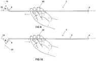
- Figure 9 shows the axis 13 of the tip deflected through an angle A in a posterior direction.
- Figure 10 shows the axis 13 of the tip deflected through an angle B in the anterior direction.
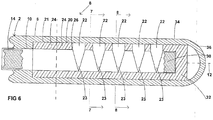
- the tip includes a tip body 20 which is preferably formed of a relatively short length of nylon tube, the length of which is in the range from 25 to 35mm and preferably about 30mm. It is preferred that the outer diameter of the body 20 is intermediate of the outer diameter and bore diameter of the main shaft 2. In this way, the distal end 6 of the main shaft 2 can be formed with a rebate 21 which can receive the proximal end 24 of the body 20, as shown in Figure 6 . In Figure 6 , part of the control rod 14 is not shown for clarity of illustration.
- the body is formed with a plurality of transversely extending slots 22.
- the arrangement is such that when the distal end of the body 20 is subjected to tension, it will tend to distend towards the side in which the slots are formed and in the opposite direction when subjected to compression, as will be described in more detail below. After tension or compression the natural elasticity of the material of the body will return it to a relaxed position in which its axis 13 is aligned with the axis 12 of the main shaft 2.
- the tip body 20 could be integrally formed at the distal end of the main shaft 2.
- the proximal end 24 of the tip body 20 is glued or bonded to the rebate 21 of the main shaft 2 so that the bore 26 of the body 20 is aligned and generally contiguous with the bore 10 of the main shaft 2, as seen in Figure 6 (i.e. the axes 12 and 13 are concentric).
- the control rod 14 is preferably moulded from nylon rod having a diameter of 2.8mm so that it is freely slidable within the bores 10 and 26. In the region where the projections 18 are located, the cross-sectional shape of the rod 14 is flattened so that the projections 18 are more prominent.
- the outer surface of the shaft 2 adjacent to the recess 16 is roughened or contains projections (not shown) to facilitate the user gripping the main shaft 2 and enabling better control of the movement of the control rod 14.
- the tip 8 includes a flexible sheath 34 which is in the form of a sleeve of silicon rubber having a rounded closed distal end 36 and a proximal end 38 which is glued or bonded to the proximal end 24 of the body 20. It is preferred that the outer diameter of the sheath 34 is the same as or approximately the same as the outer diameter of the main shaft 2.
- the slots are located on one side only of the tip body 20.
- the provision of asymmetrically located slots 22 enable the tip body 20 to be rotated, laterally displaced or bent laterally because of expansion or contraction of the slots 22 when subjected to tensile or compressive forces from the control rod 14.
- the inner ends 23 of the slots 22 are V-shaped so that each slot has an apex which enhances bending of the tip body 20 when the control rod 14 is moved.
- a similar effect could also be obtained if the inner ends 23 of the slots 22 were curved or rounded. More particularly, if the control rod 14 moves in a proximal direction (to the left), as seen in Figure 6 , the body 20 will be displaced or rotated upwardly relative to the axis 12.
- this displacement in an anterior direction is about 100°.
- the control rod has a range of movement of about 3 to 5mm and preferably about 4mm either side of a neutral position (in which the tip 8 is aligned with the main shaft 2).
- the body 20 will be displaced or rotated in the posterior direction preferably by an amount of up to about 90° relative to the axis 12. Movement of the control rod is limited by the endmost projections 18 engaging the ends of recess 16.
- an operator can grip the projections 18 of the main shaft 2 and cause movement of the control rod 14 in either a proximal or distal direction in order to cause displacement in anterior or posterior directions, as diagrammatically illustrated in Figures 9 and 10 .
- anterior and posterior are used for convenience and are the normal positions as shown in Figures 9 and 10 .
- bougie of the invention can be used in any orientation.
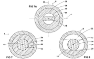
- the portion 27 of the control rod 14 which is located within the bore 26 of the body 20 is flattened so that it has good flexure in the anterior and posterior directions as diagrammatically illustrated in Figure 7A .
- This facilitates in stiffening the body 20 against displacement in directions other than the posterior and anterior directions (i.e. perpendicularly relative to these directions).
- the shape of the body 20 with the lateral slots 22 also facilitates in providing flexibility in the anterior and posterior directions whilst resisting deflections in directions perpendicular thereto.
- the flattened shape of the portion 27 of the control rod and the orientation of the slots 22 is such that the deflection of the tip 8 occurs most easily in a plane 29 which includes the axis 12 and is transverse to the lateral direction of the slots 22. It also follows that the tip 8 is more resistant to deflection in a plane 31 which is orthogonal to the plane 29, as shown in Figure 7A .
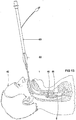
- FIGs 11 to 13 diagrammatically illustrate the manner in which the bougie 1 of the invention can be deployed in a patient 40.
- the hand 42 of an operator can be used to grip the projections 18 so as to enable control of the orientation of the tip 8 relative to the main axis of the shaft 2.
- a laryngoscope 44 is deployed so that the operator has a view of the vocal chords 46 of the patient.
- the operator can move the control rod 14 in a proximal or distal direction in order to cause displacement of the tip 8 in an anterior or posterior direction as required in order to best facilitate insertion of the tip through the vocal chords 46.
- the operator can rotate the main shaft 2 whilst manipulating the control rod so that the tip 8 can be moved through a wide range of positions relative to the anatomy of the patient.
- FIGS 15 to 17 illustrate an alternative bougie 51 of the invention which has provision for supplying oxygen to the tip 8.
- the same reference numerals have been used to denote parts which are the same as or correspond to those of the previous embodiment.
- the main shaft 2 is in the form of a tube, the interior of which constitutes an oxygen channel 53.
- the device includes a removable cap 57 which when removed forms an inlet port 62 being the proximal end of the tube which forms the main shaft 2.
- the control rod 14 includes a longitudinally extending oxygen channel 55 to permit oxygen to pass from the port 62 along the length of the tube which forms a main shaft 2 and through the body 20 of the tip.
- the sheath 34 includes an outlet port 58 at its distal end. It will be appreciated that by connecting an oxygen supply tube 54, as shown in Figure 17 , to the port 62 oxygen can be discharged to a patient from the outlet port 58.
- FIGS 18 to 22 diagrammatically illustrate a further bougie 61 constructed in accordance with the invention.
- the same reference numerals have been used to denote parts which are similar to those of the bougie 51 shown in Figures 15 to 17 .
- the main shaft 2 is in the form of a tubular body 65 which is formed with a longitudinally extending partition 67 which defines two channels 56 and 59.
- the control rod 14 is slideably mounted in the channel 59 and is generally semi-circular in cross-section so as to neatly fit within the channel 59.
- the proximal end of the channel 59 includes a barrier 60 which can be formed from a body of silicon adhesive or the like.
- the channel 59 can be used for introduction of oxygen at the port 62 and the barrier 60 prevents oxygen entering the channel 59.
- the distal end of the tubular body 65 is formed with an outlet port 58 in the sidewall of the tube which forms the main shaft 2, as shown in Figure 18 .
- Oxygen can be introduced into inlet port 62 via the oxygen supply tube 54 as before.
- the bougie 61 of Figures 18 to 22 could be used for suction purposes if a source of vacuum were coupled to the port 62.
- the device could therefore be used for removal of mucous, blood or other fluid from a patient.
- the port 62 could also be used as a passageway for a guidewire or other instrument to be inserted into the trachea of a patient.
- Figures 23 to 25 illustrate an alternative bougie 70 constructed in accordance with the invention.
- the same reference numerals have been used to denote parts which are the same as or correspond to those of previous embodiments.
- the flexible sheath 34 has been omitted for clarity of illustration.
- the distal end 30 of the control rod 14 is not directly connected to the tip body 20 but is coupled thereto by means of a wire 68.
- the wire 68 is made from stainless steel and has a diameter of about 0.24mm. In the illustrated arrangement, the wire 68 may have a length of say 49mm. It will be appreciated that braided wire could also be used.
- the proximal end 72 of the wire 68 is located within a recess 66 formed in the distal end 30 of the control rod.
- the proximal end of the wire 68 is securely fastened to the control rod by means of a body 69 of adhesive material such as epoxy resin.
- the tip body 20 is moulded with a thickened portion 74 on one side thereof where the openings to the slots 22 are located, i.e. opposite to the apices of the slots 22.
- a bore 76 is formed in the widened portion 74 as best seen in Figure 25 and the wire 68 can pass through the bore 76 to the distal end 32 of the body 20.
- the distal end 78 of the wire 68 is bent back in the proximal direction so as to extend within the bore 26 of the body 20.
- a body 71 of adhesive such as epoxy resin is then placed in the bore so as to fix the distal end 78 of the wire to the distal end 32 of the body 20.
- the bougie 70 operates in a similar manner to the previous embodiments. When the user engages the projections 18 and pulls the control rod in a distal direction, this will be translated into increased tension in the wire 68 which will cause bending of the body 20 laterally owing to the decrease in width of the slots 22. In the illustrated arrangement, when the control rod is moved proximally, the body 20 will be bent downwardly as shown in Figure 23 .
- the wire 68 will be capable of transmitting compressional forces on the end 32 so that it will be bent in the opposite direction, that is to say upwardly as seen in Figure 23 .
- the wire 68 and bore 76 function somewhat analogously to a Bowden cable.
- a prototype of this arrangement has been made and found to exhibit good flexure of the body 20 with relatively small forces being applied by the user to the projections 18.
- the ends of the projections 18 can therefore be rounded as shown in Figure 23 which makes the bougie 70 more convenient to use.
- the main shaft 2 is in the form of a nylon tube.
- the control rod 14 can also be injection moulded from nylon.
- the body 20 or sheath 34 is preferably coloured green or yellow so that it can better be seen by a user.
- the tip body or sheath may include fluorescent pigment (glow in the dark pigment) such as those available through Smooth-On, Inc. of Pennsylvania USA.
- the glow in the dark effect enhances placement of the bougie tip and provides a clear indication that the bougie tip has passed through the vocal chords and into the trachea of a patient.
- the glow in the dark effect can be enhanced by exposure of the tip to ultraviolet light prior to use.
- the bougie of the device is simple and inexpensive and can be manufactured as a disposable or single use product.
Landscapes
- Health & Medical Sciences (AREA)
- Pulmonology (AREA)
- Emergency Medicine (AREA)
- Engineering & Computer Science (AREA)
- Anesthesiology (AREA)
- Biomedical Technology (AREA)
- Heart & Thoracic Surgery (AREA)
- Hematology (AREA)
- Life Sciences & Earth Sciences (AREA)
- Animal Behavior & Ethology (AREA)
- General Health & Medical Sciences (AREA)
- Public Health (AREA)
- Veterinary Medicine (AREA)
- Otolaryngology (AREA)
- Media Introduction/Drainage Providing Device (AREA)
Description
- This invention relates to a bougie with a controllable tip.
- The introduction of an endotracheal tube (ETT) into the trachea is a common medical procedure performed during resuscitation and anaesthesia. It is referred to as "intubation" and is intended to provide a secure airway in patients who are unable to manage their breathing. Greater than 4.5 million intubations occur worldwide per year.
- This is usually performed under direct vision using a laryngoscope. Laryngoscopes come in a variety of patterns but essentially comprise a light source, a blade and a handle. Using the blade as a spatula the laryngoscope is inserted through the mouth behind the base of the tongue and is then placed above the larynx in order to visualise the vocal cords (chords). Once the laryngoscope is in place an endotracheal tube is guided manually under direct vision between the chords and into the upper trachea. Recently a number of video laryngoscopes have become available, these devices are designed to provide a clearer view of the vocal chords and surrounding structures by virtue of a camera being placed close to the tip of the blade. The image from this camera is typically displayed on a screen attached to the handle of the video-laryngoscope, or placed remotely, but within visual range of the operator.
- There are a number of situations that can make intubation difficult and in some cases impossible. These include an inability to sufficiently open the mouth due to trauma, inability to flex or extend the neck due to trauma or pathology in the cervical spine or distortion of the anatomy surrounding the glottis due to tumours, haemorrhage, etc. The inability to intubate a patient can constitute a medical emergency and in some cases can result in death. A number of techniques have been developed to help clinicians overcome some of these difficult situations.
- One technique is the use of a guide or a bougie to negotiate a pathway between the vocal chords. Once a bougie is successfully in place an endotracheal tube can be placed over the bougie and slid down to follow the bougie through the chords, this technique is commonly referred to as "railroading".
- The advantage of placing the bougie through the chords is that it is of a significantly smaller diameter (typically 4-5mm) in comparison to the ETT which can range from 5-12mm. This allows much greater visibility when guiding the bougie through the chords. With both conventional and video laryngoscopes a large diameter ETT can obscure vision of the chords. The ETT is normally moulded with a curve that allows it to follow the curved pathway from the oral opening to the chords. However, in many cases the angle at which the tip of the ETT presents itself to the opening between the chords does not allow the ETT tube to negotiate this space. Furthermore, the bougie can be made from relatively stiff material which is easier to control in terms of guiding it through the chords. Additionally, the end of the bougie may be formed with an angled tip, which provides the capacity to manoeuvre the tip through the chords by rotating the bougie so the tip can be positioned optimally to advance.
- A number of bougies are currently available for this purpose and are designed using different materials, diameters and tip angles.
- There are, however, occasions where the tip angle is insufficient or too great to position these bougies within the chords.
-
US Patent No. 3,802,440 discloses an adjustably flexible guide for assisting in placement of an endotracheal tube. The end of the guide is adjustable so as to assist in placement of a guide to permit insertion in the desired duct or body patient of the passage. With this guide it is necessary that the endotracheal tube is first placed over the guide and this has the significant disadvantage that the body of the endotracheal tube obscures the view of the vocal chords of the patient, thereby making passage of the guide and endotracheal tube through the vocal chords difficult. -
US Patent Application No. 2008/0017195 A1 discloses an intubation stylet which includes an extension member and light source. The stylet includes a handle portion which would prevent an endotracheal tube being deployed after the stylet has initially been inserted in a patient. - In other words, the bulky handles at the proximal end of the devices as disclosed in the prior art documents referred to above prevent them being utilised in the railroading technique.
- Additionally, in some circumstance it is helpful to be able to introduce oxygen into the patient's airway during the intubation process. Therefore some bougies have an internal passageway to channel oxygen from the proximal end to the distal end of the bougie, that is they are hollow. When additional oxygen is used in this way, it may be introduced in a manner that assists in ventilation. This can occur by the entrainment of air into the trachea, a technique known as jet ventilation or the agitation of surrounding air this technique is known as high frequency jet ventilation.
- According to the present invention there is provided a bougie for insertion in a patient as claimed in
claim 1. The present invention thus provides a bougie which has an adjustable tip and can be initially placed into the trachea of a patient and, after placement, an endotracheal tube can be slid along the bougie thereby facilitating correct deployment of the endotracheal tube. Preferred embodiments of the invention are defined in the dependent claims. - Preferably the tip includes a tip body with lateral formations which, when the body is subject to pulling or pushing by the control rod, causes lateral displacement of the tip in anterior and posterior directions respectively.
- Preferably further the body is tubular and the lateral formations comprise slots extending laterally through the tubular body along one side of the tubular body.
- Preferably further, the control rod extends through the tubular body and its distal end is coupled to the distal end of the tubular body so that:
- (i) when the operator slides the control rod in a proximal direction relative to the main shaft the tip is displaced in the anterior direction; and
- (ii) when the operator slides the control rod in a distal direction relative to the main shaft the tip is displaced in the posterior direction.
- An additional feature is the addition of a channel running the entire length of the device to allow the passage of oxygen from the proximal end to the distal end. The proximal end may have a removable cover to allow coupling of an oxygen supply tube. The channel may terminate at the tip of the bougie via a concentric port or, alternatively, it may terminate via a side port in the distal end of the main shaft in close proximity to the displaceable tip.
- The oxygen may pass through the existing hollow formation of the main shaft and displaceable tip with an additional channel formed in the lateral aspect of the control shaft opposite to the lateral projections. Alternatively, a specific channel may be formed within the main shaft for this purpose.
-
-
Figure 1 is a side view of a bougie constructed in accordance with the invention; -
Figure 2 is a schematic exploded view of the bougie of the invention; -
Figure 3 is a fragmentary view showing a slot in the main shaft of the bougie; -
Figure 4 is a fragmentary view of part of the control rod of the bougie; -
Figure 5 is a fragmentary exploded view of the tip of the bougie; -
Figure 6 is an enlarged axial cross-sectional view of the tip of the bougie; -
Figure 7 is a cross-sectional view along the line 7-7; -
Figure 7A is a similar view toFigure 7 through an alternative embodiment of the invention; -
Figure 8 is a cross-sectional view along the line 8-8; -
Figure 9 shows operation of the bougie in order to produce deflection in a posterior direction; -
Figure 10 is a schematic view showing operation of the bougie to produce deflection in an interior direction; -
Figure 11 is a schematic view showing insertion of the bougie through the chords of a patient; -
Figure 12 is a schematic view showing insertion of the tip of the bougie into the trachea of a patient; -
Figure 13 schematically shows railroading of an ETT on the bougie; -
Figure 14 shows the ETT deployed and the bougie removed from the patient; -
Figure 15 is a schematic longitudinal view through a modified bougie of the invention having an oxygen port therein; -
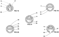
Figure 16 is a cross-sectional view along the line 16-16; -
Figure 17 is a schematic view of the oxygen inlet port; -
Figure 18 is an alternative bougie of the invention with an oxygen port; -
Figure 19 is a cross-sectional view along the line 19-19; -
Figure 20 is a cross-sectional view along the line 20-20; -
Figure 21 is a cross-sectional view along the line 21-21; -
Figure 22 is a cross-sectional view along the line 22-22; -
Figure 23 is a fragmentary longitudinal cross-section through a further alternative embodiment of the invention; -
Figure 24 is a cross-sectional view along the line 24-24; and -
Figure 25 is a cross-sectional view along the line 25-25. -
Figure 1 schematically shows abougie 1 of the invention. It includes amain shaft 2 having aproximal end 4 and adistal end 6. Adisplaceable tip 8 is located at the distal end of themain shaft 2. Themain shaft 2 is preferably in the form of a nylon tube having a length of about 600mm. It is preferred that the outer diameter is about 4mm and it has aninternal bore 10 which is 3mm in diameter, as seen inFigure 6 . Thetip 8 can be displaced relative to thelongitudinal axis 12 of themain shaft 2. As will be described in more detail below, the orientation of thetip 8 relative to theaxis 12 can be controlled by means of acontrol rod 14 which is slidably mounted within thebore 10 of themain shaft 2. - In the preferred form of the invention, the
proximal end 4 of the main tube is closed and a longitudinally extendingrecess 16 is formed in theshaft 2 in order to permit access by an operator to thecontrol rod 14. As best seen inFigure 2 , thecontrol rod 14 includeslateral projections 18 which are located in the region of therecess 16 so that they are manually accessible to an operator. As best seen inFigures 9 and 10 , an operator can grasp thebougie 1 of the invention and use his or her fingers or thumb to grip theprojections 18 on thecontrol rod 14 so that it can be axially moved within themain shaft 2 and this movement can be used to control deflection of thetip 8 relative to theaxis 12.Figure 9 shows theaxis 13 of the tip deflected through an angle A in a posterior direction.Figure 10 shows theaxis 13 of the tip deflected through an angle B in the anterior direction. - As seen in
Figures 5 to 8 , the tip includes atip body 20 which is preferably formed of a relatively short length of nylon tube, the length of which is in the range from 25 to 35mm and preferably about 30mm. It is preferred that the outer diameter of thebody 20 is intermediate of the outer diameter and bore diameter of themain shaft 2. In this way, thedistal end 6 of themain shaft 2 can be formed with arebate 21 which can receive theproximal end 24 of thebody 20, as shown inFigure 6 . InFigure 6 , part of thecontrol rod 14 is not shown for clarity of illustration. The body is formed with a plurality of transversely extendingslots 22. The arrangement is such that when the distal end of thebody 20 is subjected to tension, it will tend to distend towards the side in which the slots are formed and in the opposite direction when subjected to compression, as will be described in more detail below. After tension or compression the natural elasticity of the material of the body will return it to a relaxed position in which itsaxis 13 is aligned with theaxis 12 of themain shaft 2. - In an alternative arrangement, the
tip body 20 could be integrally formed at the distal end of themain shaft 2. - The
proximal end 24 of thetip body 20 is glued or bonded to therebate 21 of themain shaft 2 so that thebore 26 of thebody 20 is aligned and generally contiguous with thebore 10 of themain shaft 2, as seen inFigure 6 (i.e. theaxes - The
control rod 14 is preferably moulded from nylon rod having a diameter of 2.8mm so that it is freely slidable within thebores projections 18 are located, the cross-sectional shape of therod 14 is flattened so that theprojections 18 are more prominent. Preferably the outer surface of theshaft 2 adjacent to therecess 16 is roughened or contains projections (not shown) to facilitate the user gripping themain shaft 2 and enabling better control of the movement of thecontrol rod 14. - In
Figure 6 it will be seen that thedistal end 30 of thecontrol rod 14 is joined to a closeddistal end 32 of thetip body 20. Thetip 8 includes aflexible sheath 34 which is in the form of a sleeve of silicon rubber having a rounded closeddistal end 36 and a proximal end 38 which is glued or bonded to theproximal end 24 of thebody 20. It is preferred that the outer diameter of thesheath 34 is the same as or approximately the same as the outer diameter of themain shaft 2. - In the illustrated arrangement, the slots are located on one side only of the
tip body 20. The provision of asymmetrically locatedslots 22 enable thetip body 20 to be rotated, laterally displaced or bent laterally because of expansion or contraction of theslots 22 when subjected to tensile or compressive forces from thecontrol rod 14. In this arrangement the inner ends 23 of theslots 22 are V-shaped so that each slot has an apex which enhances bending of thetip body 20 when thecontrol rod 14 is moved. A similar effect could also be obtained if the inner ends 23 of theslots 22 were curved or rounded. More particularly, if thecontrol rod 14 moves in a proximal direction (to the left), as seen inFigure 6 , thebody 20 will be displaced or rotated upwardly relative to theaxis 12. Preferably this displacement in an anterior direction is about 100°. In the illustrated arrangement the control rod has a range of movement of about 3 to 5mm and preferably about 4mm either side of a neutral position (in which thetip 8 is aligned with the main shaft 2). On the other hand, if thecontrol rod 14 is moved in the distal direction (to the right), thebody 20 will be displaced or rotated in the posterior direction preferably by an amount of up to about 90° relative to theaxis 12. Movement of the control rod is limited by theendmost projections 18 engaging the ends ofrecess 16. As indicated above, an operator can grip theprojections 18 of themain shaft 2 and cause movement of thecontrol rod 14 in either a proximal or distal direction in order to cause displacement in anterior or posterior directions, as diagrammatically illustrated inFigures 9 and 10 . It is to be understood that the terms anterior and posterior are used for convenience and are the normal positions as shown inFigures 9 and 10 . It is to be understood, of course, that the bougie of the invention can be used in any orientation. - In the preferred embodiment, the
portion 27 of thecontrol rod 14 which is located within thebore 26 of thebody 20 is flattened so that it has good flexure in the anterior and posterior directions as diagrammatically illustrated inFigure 7A . This facilitates in stiffening thebody 20 against displacement in directions other than the posterior and anterior directions (i.e. perpendicularly relative to these directions). It will also be appreciated that the shape of thebody 20 with thelateral slots 22 also facilitates in providing flexibility in the anterior and posterior directions whilst resisting deflections in directions perpendicular thereto. More particularly, the flattened shape of theportion 27 of the control rod and the orientation of theslots 22 is such that the deflection of thetip 8 occurs most easily in aplane 29 which includes theaxis 12 and is transverse to the lateral direction of theslots 22. It also follows that thetip 8 is more resistant to deflection in aplane 31 which is orthogonal to theplane 29, as shown inFigure 7A . -
Figures 11 to 13 diagrammatically illustrate the manner in which thebougie 1 of the invention can be deployed in apatient 40. InFigure 11 it will be seen that thehand 42 of an operator can be used to grip theprojections 18 so as to enable control of the orientation of thetip 8 relative to the main axis of theshaft 2. InFigure 11 alaryngoscope 44 is deployed so that the operator has a view of thevocal chords 46 of the patient. During this stage of the deployment, the operator can move thecontrol rod 14 in a proximal or distal direction in order to cause displacement of thetip 8 in an anterior or posterior direction as required in order to best facilitate insertion of the tip through thevocal chords 46. The operator can rotate themain shaft 2 whilst manipulating the control rod so that thetip 8 can be moved through a wide range of positions relative to the anatomy of the patient. - In
Figure 12 it will be seen that thetip 8 has passed beyond thechords 46 and into thetrachea 48 of the patient. Once in this position, the operator can then mount an endotracheal tube (ETT) 50 over the proximal end of themain shaft 2 of the bougie and then slide theETT 50 along the length of the main shaft so that itscuff 52 is guided past thevocal chords 46 of the patient and is correctly located in thetrachea 48 of the patient. Once in this position, thecuff 52 of theETT 50 can be inflated and thebougie 1 of the invention removed, as shown inFigure 14 . -
Figures 15 to 17 illustrate analternative bougie 51 of the invention which has provision for supplying oxygen to thetip 8. The same reference numerals have been used to denote parts which are the same as or correspond to those of the previous embodiment. It will be seen that themain shaft 2 is in the form of a tube, the interior of which constitutes anoxygen channel 53. The device includes aremovable cap 57 which when removed forms aninlet port 62 being the proximal end of the tube which forms themain shaft 2. In this embodiment, thecontrol rod 14 includes a longitudinally extendingoxygen channel 55 to permit oxygen to pass from theport 62 along the length of the tube which forms amain shaft 2 and through thebody 20 of the tip. Thesheath 34 includes anoutlet port 58 at its distal end. It will be appreciated that by connecting anoxygen supply tube 54, as shown inFigure 17 , to theport 62 oxygen can be discharged to a patient from theoutlet port 58. -
Figures 18 to 22 diagrammatically illustrate afurther bougie 61 constructed in accordance with the invention. The same reference numerals have been used to denote parts which are similar to those of the bougie 51 shown inFigures 15 to 17 . In this embodiment, themain shaft 2 is in the form of atubular body 65 which is formed with alongitudinally extending partition 67 which defines twochannels control rod 14 is slideably mounted in thechannel 59 and is generally semi-circular in cross-section so as to neatly fit within thechannel 59. The proximal end of thechannel 59 includes abarrier 60 which can be formed from a body of silicon adhesive or the like. Thechannel 59 can be used for introduction of oxygen at theport 62 and thebarrier 60 prevents oxygen entering thechannel 59. The distal end of thetubular body 65 is formed with anoutlet port 58 in the sidewall of the tube which forms themain shaft 2, as shown inFigure 18 . Oxygen can be introduced intoinlet port 62 via theoxygen supply tube 54 as before. - It will be appreciated that the
bougie 61 ofFigures 18 to 22 could be used for suction purposes if a source of vacuum were coupled to theport 62. The device could therefore be used for removal of mucous, blood or other fluid from a patient. Theport 62 could also be used as a passageway for a guidewire or other instrument to be inserted into the trachea of a patient. -
Figures 23 to 25 illustrate analternative bougie 70 constructed in accordance with the invention. The same reference numerals have been used to denote parts which are the same as or correspond to those of previous embodiments. InFigure 23 theflexible sheath 34 has been omitted for clarity of illustration. The main difference between the bougie 70 and the previous embodiments is that thedistal end 30 of thecontrol rod 14 is not directly connected to thetip body 20 but is coupled thereto by means of awire 68. Preferably, thewire 68 is made from stainless steel and has a diameter of about 0.24mm. In the illustrated arrangement, thewire 68 may have a length of say 49mm. It will be appreciated that braided wire could also be used. - The
proximal end 72 of thewire 68 is located within a recess 66 formed in thedistal end 30 of the control rod. The proximal end of thewire 68 is securely fastened to the control rod by means of abody 69 of adhesive material such as epoxy resin. In the arrangement shown inFigure 23 , thetip body 20 is moulded with a thickenedportion 74 on one side thereof where the openings to theslots 22 are located, i.e. opposite to the apices of theslots 22. A bore 76 is formed in the widenedportion 74 as best seen inFigure 25 and thewire 68 can pass through thebore 76 to thedistal end 32 of thebody 20. In the illustrated arrangement, thedistal end 78 of thewire 68 is bent back in the proximal direction so as to extend within thebore 26 of thebody 20. Abody 71 of adhesive such as epoxy resin is then placed in the bore so as to fix thedistal end 78 of the wire to thedistal end 32 of thebody 20. The bougie 70 operates in a similar manner to the previous embodiments. When the user engages theprojections 18 and pulls the control rod in a distal direction, this will be translated into increased tension in thewire 68 which will cause bending of thebody 20 laterally owing to the decrease in width of theslots 22. In the illustrated arrangement, when the control rod is moved proximally, thebody 20 will be bent downwardly as shown inFigure 23 . On the other hand, if the user pushes the control rod in a distal direction, thewire 68 will be capable of transmitting compressional forces on theend 32 so that it will be bent in the opposite direction, that is to say upwardly as seen inFigure 23 . It will be appreciated that thewire 68 and bore 76 function somewhat analogously to a Bowden cable. A prototype of this arrangement has been made and found to exhibit good flexure of thebody 20 with relatively small forces being applied by the user to theprojections 18. The ends of theprojections 18 can therefore be rounded as shown inFigure 23 which makes the bougie 70 more convenient to use. - As mentioned above, the
main shaft 2 is in the form of a nylon tube. Thecontrol rod 14 can also be injection moulded from nylon. Thebody 20 orsheath 34 is preferably coloured green or yellow so that it can better be seen by a user. Preferably further, the tip body or sheath may include fluorescent pigment (glow in the dark pigment) such as those available through Smooth-On, Inc. of Pennsylvania USA. In some applications, the glow in the dark effect enhances placement of the bougie tip and provides a clear indication that the bougie tip has passed through the vocal chords and into the trachea of a patient. The glow in the dark effect can be enhanced by exposure of the tip to ultraviolet light prior to use. - It will be appreciated that the bougie of the device is simple and inexpensive and can be manufactured as a disposable or single use product.
LIST OF PARTS bougie 1 endotracheal tube 50 main shaft 2 bougie 51 proximal end 4 cuff 52 distal end 6 oxygen channel 53 displaceable tip 8 oxygen supply tube 54 internal bore 10 oxygen channel 55 longitudinal axis 12 channel 56 axis 13 removable cap 57 control rod 14 outlet port 58 recess 16 channel 59 lateral projections 18 barrier 60 tip body 20 bougie 61 rebate 21 inlet port 62 slots 22 tubular body 65 inner ends 23 recess 66 proximal end 24 partition 67 bore 26 wire 68 portion 27 body 69 plane 29 bougie 70 distal end 30 body 71 plane 31 proximal end 72 distal end 32 portion 74 flexible sheath 34 bore 76 distal end 36 distal end 78 proximal end 38 patient 40 hand 42 laryngoscope 44 vocal chords 46 trachea 48
Claims (15)
- A bougie (1) for insertion in a patient (40), the bougie (1) including:(i) a main shaft (2) in the form of a tube having proximal and distal ends (4, 6) and a bore (10) extending axially therein;(ii) a longitudinally extending recess (16) formed in the shaft (2);(iii) a movable tip (8) having proximal and distal ends (24, 36), the proximal end of the movable tip being connected to the distal end (4) of the main shaft (2);(iv) a control member (14) having proximal and distal ends (38, 30), the control member (14) being mounted for sliding movement in the bore (10) of the main shaft (2);(v) the distal end (30) of the control member (14) being coupled to the distal end (36) of the movable tip (8), the arrangement being such that an operator can slide the control member (14) relative to the main shaft (2) so as to cause displacement of the movable tip (8) relative to the bore of the main shaft (2),characterised in that;(vi) projections (18) are provided on the control member (14) in the region of said recess (16);(vii) the arrangement being such that an operator can grip said projections (18) for sliding said control member (14) relative to said main shaft (2) so as to cause displacement of said movable tip (8) relative to said bore of said main shaft (2), so that the arrangement of the tube and projections (18) is such that an operator can pass the movable tip (8) into the trachea (48) of a patient (40) and then mount the distal end of an endotracheal tube (ETT) (50) over the proximal end (4) of the main shaft (2) so that the ETT (50) can be correctly located in the trachea (48) of the patient and thereafter removed from the ETT (50).
- A bougie as claimed in claim 1, wherein the control member is a control rod (14).
- A bougie as claimed in claim 2, wherein the distal end (30) of the control member is coupled to the distal end (36) of the movable tip by means of a control wire (68).
- A bougie as claimed in claim 2 or 3, wherein the movable tip (8) includes a tip body (20) with lateral formations which, when the tip body is subject to pulling or pushing by the control rod (14), causes lateral displacement of the movable tip (8) in anterior and posterior directions respectively.
- A bougie as claimed in claim 4, wherein the tip body (20) is tubular and the lateral formations comprise slots (22) extending laterally through the tubular body (20) along one side of the tubular body.
- A bougie as claimed in claim 5, wherein the control rod (14) extends through the main shaft (2) and its distal end (30) is coupled to a distal end (6) of the main shaft (2) so that:(i) when the operator slides the control rod (14) in a proximal direction relative to the main shaft (2) the movable tip (8) is displaced in the anterior direction; and(ii) when the operator slides the control rod (14) in a distal direction relative to the main shaft (2) the movable tip (8) is displaced in the posterior direction.
- A bougie as claimed in any preceding claim, wherein the main shaft (2) and control member (14) are flexible.
- A bougie as claimed in claim 4 or any claim dependent on claim 4, wherein the movable tip (8) includes a sheath (34) which covers the tip body (20).
- A bougie as claimed in claim 8, wherein the sheath (34) is formed from resilient material and has a closed distal end (36) and a proximal end (38) which is joined to the distal end of the main shaft (2).
- A bougie as claimed in any preceding claim, wherein the movable tip (8) can be displaced through about 190° relative to the axial direction of the main shaft (2).
- A bougie as claimed in claim 4 or any one of claims 5 to 10 appended directly or indirectly to claim 4, wherein the movable tip (8) can be displaced through about 100° in the anterior direction and about 90° in the posterior direction.
- A bougie as claimed in any preceding claim, wherein in a relaxed position of the movable tip (8) it is axially aligned with an axis (12) of the main shaft (2).
- A bougie as claimed in claim 3 or any one of claims 4 to 12 appended directly or indirectly to claim 3, wherein the main shaft (2) and movable tip (8) are generally tubular in shape and have a common axis (12) when the movable tip is in a neutral position and wherein the control wire (68) extends in a longitudinal direction but is laterally offset relative to said axis (12).
- A bougie as claimed in 13, wherein the movable tip (8) includes a passageway (76) through which the control wire (68) passes, the arrangement being such that the control wire (68) can transmit tensile and compressive forces to the distal end (36) of the movable tip.
- A bougie as claimed in claim 13 or 14 appended directly or indirectly to claim 5, wherein the control wire (68) is offset towards said one side.
Applications Claiming Priority (2)
| Application Number | Priority Date | Filing Date | Title |
|---|---|---|---|
| AU2013904281A AU2013904281A0 (en) | 2013-11-06 | A bougie with a controllable tip | |
| PCT/AU2014/050329 WO2015066763A1 (en) | 2013-11-06 | 2014-11-03 | A bougie with a controllable tip |
Publications (3)
| Publication Number | Publication Date |
|---|---|
| EP3065803A1 EP3065803A1 (en) | 2016-09-14 |
| EP3065803A4 EP3065803A4 (en) | 2017-06-28 |
| EP3065803B1 true EP3065803B1 (en) | 2019-03-20 |
Family
ID=53040706
Family Applications (1)
| Application Number | Title | Priority Date | Filing Date |
|---|---|---|---|
| EP14859483.1A Active EP3065803B1 (en) | 2013-11-06 | 2014-11-03 | A bougie with a controllable tip |
Country Status (7)
| Country | Link |
|---|---|
| US (1) | US10478578B2 (en) |
| EP (1) | EP3065803B1 (en) |
| JP (1) | JP6745217B2 (en) |
| CN (1) | CN105873628B (en) |
| AU (1) | AU2014346337B2 (en) |
| ES (1) | ES2730016T3 (en) |
| WO (1) | WO2015066763A1 (en) |
Cited By (1)
| Publication number | Priority date | Publication date | Assignee | Title |
|---|---|---|---|---|
| EP4272792A1 (en) | 2022-05-04 | 2023-11-08 | Albert-Ludwigs-Universität Freiburg | Medical instrument for intubation |
Families Citing this family (28)
| Publication number | Priority date | Publication date | Assignee | Title |
|---|---|---|---|---|
| US10149957B2 (en) | 2013-10-03 | 2018-12-11 | University Of Utah Research Foundation | Tracheal intubation system including a laryngoscope |
| US11633093B2 (en) * | 2014-08-08 | 2023-04-25 | Wm & Dg, Inc. | Medical devices and methods of placement |
| US11147442B2 (en) * | 2014-08-08 | 2021-10-19 | Wm & Dg, Inc. | Medical devices and methods of placement |
| GB201519582D0 (en) * | 2015-11-05 | 2015-12-23 | Intersurgical Ag | Improvements relating to the manufacture of medical devices |
| CN110022923B (en) | 2016-10-21 | 2022-09-27 | 声带通有限责任公司 | Hinged stylet |
| US11051682B2 (en) | 2017-08-31 | 2021-07-06 | Wm & Dg, Inc. | Medical devices with camera and methods of placement |
| US11033180B2 (en) | 2017-11-03 | 2021-06-15 | Aircraft Medical Ltd. | Video laryngoscope systems and methods |
| US10835115B2 (en) | 2017-11-15 | 2020-11-17 | Aircraft Medical Ltd. | Multifunctional visualization instrument |
| US20210213224A1 (en) * | 2018-05-14 | 2021-07-15 | Steven VENTICINQUE | Tracheal cannulation device |
| US11684251B2 (en) * | 2019-03-01 | 2023-06-27 | Covidien Ag | Multifunctional visualization instrument with orientation control |
| US11696671B2 (en) | 2019-08-19 | 2023-07-11 | Covidien Ag | Steerable endoscope with motion alignment |
| US12232691B2 (en) | 2019-10-31 | 2025-02-25 | Covidien Ag | User interface for steerable endoscope |
| US11724053B2 (en) * | 2020-04-01 | 2023-08-15 | Boyi Gao | Device for gripping and securing an intubation bougie |
| GB202006151D0 (en) * | 2020-04-27 | 2020-06-10 | Smiths Medical International Ltd | Reinforced medico-surgical tubes anbd their manufacture |
| CN114642807A (en) * | 2020-12-18 | 2022-06-21 | Tjb医疗股份有限公司 | Flexible articulated intubation tool |
| GR1010177B (en) | 2020-12-19 | 2022-02-18 | Συμεων Γεωργιου Γρηγοριου | Articulated tube introducer (bougie) for intubation |
| IT202100001085A1 (en) * | 2021-01-22 | 2022-07-22 | Medsniper S R L | ENDOTRACHEAL TUBE |
| US12295719B2 (en) | 2021-05-06 | 2025-05-13 | Covidien Lp | Endoscope navigation system with updating anatomy model |
| WO2022251635A1 (en) * | 2021-05-27 | 2022-12-01 | Through the Cords, LLC | Systems, devices, and techniques for positioning tubes |
| US12661466B2 (en) * | 2021-08-27 | 2026-06-23 | Michael Peck | Sequential stylet |
| US12697020B2 (en) | 2021-10-20 | 2026-08-04 | Covidien Lp | Video laryngoscope image file management systems and methods |
| US12532069B2 (en) | 2021-10-20 | 2026-01-20 | Covidien Lp | Video laryngoscope wireless hub systems and methods |
| US12557979B2 (en) | 2022-02-07 | 2026-02-24 | Covidien Lp | Video laryngoscope with window for infrared pairing |
| KR102533199B1 (en) * | 2022-07-07 | 2023-05-15 | 석화영 | Airway cannula unit |
| USD1120318S1 (en) | 2022-10-19 | 2026-03-24 | Covidien Lp | Media module relay for video laryngoscope |
| US12667243B2 (en) | 2023-04-27 | 2026-06-30 | Covidien Lp | Articulating endoscope with working channel |
| US12697021B2 (en) | 2023-05-31 | 2026-08-04 | Covidien Lp | Video laryngoscope and medical device wireless video transfer |
| WO2025154068A1 (en) * | 2024-01-15 | 2025-07-24 | Mor Research Applications Ltd. | A guide device with a bendable tip for endotracheal intubation |
Family Cites Families (24)
| Publication number | Priority date | Publication date | Assignee | Title |
|---|---|---|---|---|
| US3802440A (en) * | 1972-12-19 | 1974-04-09 | M Salem | Intubation guide |
| US4512765A (en) | 1983-06-09 | 1985-04-23 | Rudolph Muto | Selective tracheal bronchial catheter |
| US4655214A (en) * | 1984-06-28 | 1987-04-07 | Linder Gerald S | Inflatable introducer for aiding the intubation of catheters and endotracheal tubes |
| US4949716A (en) * | 1988-10-31 | 1990-08-21 | Medical Devices, Inc. | Nasal intubation adjunct |
| US5127393A (en) * | 1991-05-28 | 1992-07-07 | Medilase, Inc. | Flexible endoscope with rigid introducer |
| US5842973A (en) * | 1994-05-17 | 1998-12-01 | Bullard; James Roger | Nasal intubation apparatus |
| JPH0838613A (en) * | 1994-05-27 | 1996-02-13 | Terumo Corp | Catheter controls |
| US5827178A (en) | 1997-01-02 | 1998-10-27 | Berall; Jonathan | Laryngoscope for use in trachea intubation |
| FR2758089B1 (en) * | 1997-01-06 | 1999-03-05 | Georges Boussignac | METHOD AND DEVICE FOR EXCHANGING RESPIRATORY TUBE IN THE TRACHEA OF A PATIENT |
| US6890298B2 (en) | 1999-10-14 | 2005-05-10 | Karl Storz Gmbh & Co. Kg | Video laryngoscope with detachable light and image guides |
| US6668832B2 (en) | 2001-12-28 | 2003-12-30 | The Regents Of The University Of California | Endotracheal tube |
| AU2002100213A4 (en) | 2002-03-21 | 2002-06-13 | Joe Brimacombe | Dual fuction bougie |
| US7458375B2 (en) * | 2006-09-01 | 2008-12-02 | Ai Medical Devices, Inc. | Endotracheal intubation device |
| US8505531B2 (en) * | 2006-06-01 | 2013-08-13 | Truphatek International Ltd. | Hand operated articulated intubation stylet |
| US8746239B2 (en) | 2006-07-19 | 2014-06-10 | Douglas K. Yoshida | Extendable lighted intubation stylet |
| AU2008202529A1 (en) * | 2007-06-15 | 2009-01-08 | Cathrx Ltd | Single use deflectable stylet |
| US20090192355A1 (en) | 2008-01-28 | 2009-07-30 | Mauricio Mejia | Scope for managing difficult pathways and method to improve visibility of the same |
| CN101919737B (en) * | 2010-08-03 | 2012-07-11 | 安瑞医疗器械(杭州)有限公司 | A medical device for interventional diagnosis and treatment of gallbladder disease |
| US20120073572A1 (en) * | 2010-09-24 | 2012-03-29 | Li Michael Y | Intubation Stylet & Endotracheal Tube |
| US9750912B2 (en) * | 2011-05-04 | 2017-09-05 | The Regents Of The University Of Michigan | Intubation device |
| US9265908B2 (en) * | 2012-02-08 | 2016-02-23 | Richard Shockley | Intubating stylette device and related methods |
| US9010320B2 (en) * | 2012-03-12 | 2015-04-21 | Furman Medical Llc | Manually articulated intubation stylet, intubation device and intubation method |
| US10149957B2 (en) * | 2013-10-03 | 2018-12-11 | University Of Utah Research Foundation | Tracheal intubation system including a laryngoscope |
| US9199051B2 (en) | 2014-02-12 | 2015-12-01 | Anton BOOTH | System and method for facilitating an intubation |
-
2014
- 2014-11-03 WO PCT/AU2014/050329 patent/WO2015066763A1/en not_active Ceased
- 2014-11-03 CN CN201480072037.3A patent/CN105873628B/en active Active
- 2014-11-03 US US15/034,890 patent/US10478578B2/en active Active
- 2014-11-03 EP EP14859483.1A patent/EP3065803B1/en active Active
- 2014-11-03 AU AU2014346337A patent/AU2014346337B2/en active Active
- 2014-11-03 ES ES14859483T patent/ES2730016T3/en active Active
- 2014-11-03 JP JP2016528138A patent/JP6745217B2/en active Active
Non-Patent Citations (1)
| Title |
|---|
| None * |
Cited By (2)
| Publication number | Priority date | Publication date | Assignee | Title |
|---|---|---|---|---|
| EP4272792A1 (en) | 2022-05-04 | 2023-11-08 | Albert-Ludwigs-Universität Freiburg | Medical instrument for intubation |
| WO2023213612A1 (en) | 2022-05-04 | 2023-11-09 | Albert-Ludwigs-Universität Freiburg | Medical instrument for intubation |
Also Published As
| Publication number | Publication date |
|---|---|
| EP3065803A1 (en) | 2016-09-14 |
| JP6745217B2 (en) | 2020-08-26 |
| ES2730016T3 (en) | 2019-11-07 |
| US20160279365A1 (en) | 2016-09-29 |
| AU2014346337A1 (en) | 2016-05-19 |
| CN105873628B (en) | 2018-11-09 |
| CN105873628A (en) | 2016-08-17 |
| AU2014346337B2 (en) | 2019-07-18 |
| US10478578B2 (en) | 2019-11-19 |
| JP2016535637A (en) | 2016-11-17 |
| WO2015066763A1 (en) | 2015-05-14 |
| EP3065803A4 (en) | 2017-06-28 |
Similar Documents
| Publication | Publication Date | Title |
|---|---|---|
| AU2014346337B2 (en) | A bougie with a controllable tip | |
| KR102478836B1 (en) | System and method for facilitating an intubation | |
| US11678794B2 (en) | Side loading articulating laryngeal access system | |
| US20180272092A1 (en) | Tracheal intubation system including a laryngoscope | |
| US20180110950A1 (en) | Articulating stylet | |
| US20210260320A1 (en) | Intubating endoscopic device | |
| EP2640255A1 (en) | A tracheal intubation guide | |
| US9579476B2 (en) | Device for introducing an airway tube into the trachea | |
| US20140128681A1 (en) | Intubation guide assembly | |
| US20180085545A1 (en) | Intubating endoscopic device | |
| US20210093817A1 (en) | Devices and methods for introducing an endotracheal tube | |
| HK1228317A1 (en) | System and method for facilitating an intubation |
Legal Events
| Date | Code | Title | Description |
|---|---|---|---|
| PUAI | Public reference made under article 153(3) epc to a published international application that has entered the european phase |
Free format text: ORIGINAL CODE: 0009012 |
|
| 17P | Request for examination filed |
Effective date: 20160504 |
|
| AK | Designated contracting states |
Kind code of ref document: A1 Designated state(s): AL AT BE BG CH CY CZ DE DK EE ES FI FR GB GR HR HU IE IS IT LI LT LU LV MC MK MT NL NO PL PT RO RS SE SI SK SM TR |
|
| AX | Request for extension of the european patent |
Extension state: BA ME |
|
| DAX | Request for extension of the european patent (deleted) | ||
| A4 | Supplementary search report drawn up and despatched |
Effective date: 20170531 |
|
| RIC1 | Information provided on ipc code assigned before grant |
Ipc: A61B 17/24 20060101ALI20170524BHEP Ipc: A61M 16/04 20060101AFI20170524BHEP Ipc: A61B 17/00 20060101ALI20170524BHEP Ipc: A61M 25/01 20060101ALI20170524BHEP |
|
| GRAP | Despatch of communication of intention to grant a patent |
Free format text: ORIGINAL CODE: EPIDOSNIGR1 |
|
| STAA | Information on the status of an ep patent application or granted ep patent |
Free format text: STATUS: GRANT OF PATENT IS INTENDED |
|
| INTG | Intention to grant announced |
Effective date: 20181026 |
|
| GRAS | Grant fee paid |
Free format text: ORIGINAL CODE: EPIDOSNIGR3 |
|
| GRAA | (expected) grant |
Free format text: ORIGINAL CODE: 0009210 |
|
| STAA | Information on the status of an ep patent application or granted ep patent |
Free format text: STATUS: THE PATENT HAS BEEN GRANTED |
|
| AK | Designated contracting states |
Kind code of ref document: B1 Designated state(s): AL AT BE BG CH CY CZ DE DK EE ES FI FR GB GR HR HU IE IS IT LI LT LU LV MC MK MT NL NO PL PT RO RS SE SI SK SM TR |
|
| REG | Reference to a national code |
Ref country code: GB Ref legal event code: FG4D |
|
| REG | Reference to a national code |
Ref country code: CH Ref legal event code: EP |
|
| REG | Reference to a national code |
Ref country code: DE Ref legal event code: R096 Ref document number: 602014043405 Country of ref document: DE |
|
| REG | Reference to a national code |
Ref country code: AT Ref legal event code: REF Ref document number: 1109890 Country of ref document: AT Kind code of ref document: T Effective date: 20190415 |
|
| REG | Reference to a national code |
Ref country code: IE Ref legal event code: FG4D |
|
| REG | Reference to a national code |
Ref country code: NL Ref legal event code: MP Effective date: 20190320 |
|
| PG25 | Lapsed in a contracting state [announced via postgrant information from national office to epo] |
Ref country code: LT Free format text: LAPSE BECAUSE OF FAILURE TO SUBMIT A TRANSLATION OF THE DESCRIPTION OR TO PAY THE FEE WITHIN THE PRESCRIBED TIME-LIMIT Effective date: 20190320 Ref country code: FI Free format text: LAPSE BECAUSE OF FAILURE TO SUBMIT A TRANSLATION OF THE DESCRIPTION OR TO PAY THE FEE WITHIN THE PRESCRIBED TIME-LIMIT Effective date: 20190320 Ref country code: NO Free format text: LAPSE BECAUSE OF FAILURE TO SUBMIT A TRANSLATION OF THE DESCRIPTION OR TO PAY THE FEE WITHIN THE PRESCRIBED TIME-LIMIT Effective date: 20190620 Ref country code: SE Free format text: LAPSE BECAUSE OF FAILURE TO SUBMIT A TRANSLATION OF THE DESCRIPTION OR TO PAY THE FEE WITHIN THE PRESCRIBED TIME-LIMIT Effective date: 20190320 |
|
| REG | Reference to a national code |
Ref country code: LT Ref legal event code: MG4D |
|
| PG25 | Lapsed in a contracting state [announced via postgrant information from national office to epo] |
Ref country code: RS Free format text: LAPSE BECAUSE OF FAILURE TO SUBMIT A TRANSLATION OF THE DESCRIPTION OR TO PAY THE FEE WITHIN THE PRESCRIBED TIME-LIMIT Effective date: 20190320 Ref country code: GR Free format text: LAPSE BECAUSE OF FAILURE TO SUBMIT A TRANSLATION OF THE DESCRIPTION OR TO PAY THE FEE WITHIN THE PRESCRIBED TIME-LIMIT Effective date: 20190621 Ref country code: HR Free format text: LAPSE BECAUSE OF FAILURE TO SUBMIT A TRANSLATION OF THE DESCRIPTION OR TO PAY THE FEE WITHIN THE PRESCRIBED TIME-LIMIT Effective date: 20190320 Ref country code: LV Free format text: LAPSE BECAUSE OF FAILURE TO SUBMIT A TRANSLATION OF THE DESCRIPTION OR TO PAY THE FEE WITHIN THE PRESCRIBED TIME-LIMIT Effective date: 20190320 Ref country code: BG Free format text: LAPSE BECAUSE OF FAILURE TO SUBMIT A TRANSLATION OF THE DESCRIPTION OR TO PAY THE FEE WITHIN THE PRESCRIBED TIME-LIMIT Effective date: 20190620 Ref country code: NL Free format text: LAPSE BECAUSE OF FAILURE TO SUBMIT A TRANSLATION OF THE DESCRIPTION OR TO PAY THE FEE WITHIN THE PRESCRIBED TIME-LIMIT Effective date: 20190320 |
|
| REG | Reference to a national code |
Ref country code: AT Ref legal event code: MK05 Ref document number: 1109890 Country of ref document: AT Kind code of ref document: T Effective date: 20190320 |
|
| PG25 | Lapsed in a contracting state [announced via postgrant information from national office to epo] |
Ref country code: SK Free format text: LAPSE BECAUSE OF FAILURE TO SUBMIT A TRANSLATION OF THE DESCRIPTION OR TO PAY THE FEE WITHIN THE PRESCRIBED TIME-LIMIT Effective date: 20190320 Ref country code: RO Free format text: LAPSE BECAUSE OF FAILURE TO SUBMIT A TRANSLATION OF THE DESCRIPTION OR TO PAY THE FEE WITHIN THE PRESCRIBED TIME-LIMIT Effective date: 20190320 Ref country code: CZ Free format text: LAPSE BECAUSE OF FAILURE TO SUBMIT A TRANSLATION OF THE DESCRIPTION OR TO PAY THE FEE WITHIN THE PRESCRIBED TIME-LIMIT Effective date: 20190320 Ref country code: PT Free format text: LAPSE BECAUSE OF FAILURE TO SUBMIT A TRANSLATION OF THE DESCRIPTION OR TO PAY THE FEE WITHIN THE PRESCRIBED TIME-LIMIT Effective date: 20190720 Ref country code: AL Free format text: LAPSE BECAUSE OF FAILURE TO SUBMIT A TRANSLATION OF THE DESCRIPTION OR TO PAY THE FEE WITHIN THE PRESCRIBED TIME-LIMIT Effective date: 20190320 Ref country code: EE Free format text: LAPSE BECAUSE OF FAILURE TO SUBMIT A TRANSLATION OF THE DESCRIPTION OR TO PAY THE FEE WITHIN THE PRESCRIBED TIME-LIMIT Effective date: 20190320 |
|
| REG | Reference to a national code |
Ref country code: ES Ref legal event code: FG2A Ref document number: 2730016 Country of ref document: ES Kind code of ref document: T3 Effective date: 20191107 |
|
| PG25 | Lapsed in a contracting state [announced via postgrant information from national office to epo] |
Ref country code: PL Free format text: LAPSE BECAUSE OF FAILURE TO SUBMIT A TRANSLATION OF THE DESCRIPTION OR TO PAY THE FEE WITHIN THE PRESCRIBED TIME-LIMIT Effective date: 20190320 Ref country code: SM Free format text: LAPSE BECAUSE OF FAILURE TO SUBMIT A TRANSLATION OF THE DESCRIPTION OR TO PAY THE FEE WITHIN THE PRESCRIBED TIME-LIMIT Effective date: 20190320 |
|
| PG25 | Lapsed in a contracting state [announced via postgrant information from national office to epo] |
Ref country code: IS Free format text: LAPSE BECAUSE OF FAILURE TO SUBMIT A TRANSLATION OF THE DESCRIPTION OR TO PAY THE FEE WITHIN THE PRESCRIBED TIME-LIMIT Effective date: 20190720 Ref country code: AT Free format text: LAPSE BECAUSE OF FAILURE TO SUBMIT A TRANSLATION OF THE DESCRIPTION OR TO PAY THE FEE WITHIN THE PRESCRIBED TIME-LIMIT Effective date: 20190320 |
|
| REG | Reference to a national code |
Ref country code: DE Ref legal event code: R097 Ref document number: 602014043405 Country of ref document: DE |
|
| PLBE | No opposition filed within time limit |
Free format text: ORIGINAL CODE: 0009261 |
|
| STAA | Information on the status of an ep patent application or granted ep patent |
Free format text: STATUS: NO OPPOSITION FILED WITHIN TIME LIMIT |
|
| PG25 | Lapsed in a contracting state [announced via postgrant information from national office to epo] |
Ref country code: DK Free format text: LAPSE BECAUSE OF FAILURE TO SUBMIT A TRANSLATION OF THE DESCRIPTION OR TO PAY THE FEE WITHIN THE PRESCRIBED TIME-LIMIT Effective date: 20190320 |
|
| 26N | No opposition filed |
Effective date: 20200102 |
|
| PG25 | Lapsed in a contracting state [announced via postgrant information from national office to epo] |
Ref country code: SI Free format text: LAPSE BECAUSE OF FAILURE TO SUBMIT A TRANSLATION OF THE DESCRIPTION OR TO PAY THE FEE WITHIN THE PRESCRIBED TIME-LIMIT Effective date: 20190320 |
|
| PG25 | Lapsed in a contracting state [announced via postgrant information from national office to epo] |
Ref country code: TR Free format text: LAPSE BECAUSE OF FAILURE TO SUBMIT A TRANSLATION OF THE DESCRIPTION OR TO PAY THE FEE WITHIN THE PRESCRIBED TIME-LIMIT Effective date: 20190320 |
|
| REG | Reference to a national code |
Ref country code: CH Ref legal event code: PL |
|
| PG25 | Lapsed in a contracting state [announced via postgrant information from national office to epo] |
Ref country code: MC Free format text: LAPSE BECAUSE OF FAILURE TO SUBMIT A TRANSLATION OF THE DESCRIPTION OR TO PAY THE FEE WITHIN THE PRESCRIBED TIME-LIMIT Effective date: 20190320 Ref country code: CH Free format text: LAPSE BECAUSE OF NON-PAYMENT OF DUE FEES Effective date: 20191130 Ref country code: LI Free format text: LAPSE BECAUSE OF NON-PAYMENT OF DUE FEES Effective date: 20191130 Ref country code: LU Free format text: LAPSE BECAUSE OF NON-PAYMENT OF DUE FEES Effective date: 20191103 |
|
| REG | Reference to a national code |
Ref country code: BE Ref legal event code: MM Effective date: 20191130 |
|
| PG25 | Lapsed in a contracting state [announced via postgrant information from national office to epo] |
Ref country code: IE Free format text: LAPSE BECAUSE OF NON-PAYMENT OF DUE FEES Effective date: 20191103 |
|
| PG25 | Lapsed in a contracting state [announced via postgrant information from national office to epo] |
Ref country code: BE Free format text: LAPSE BECAUSE OF NON-PAYMENT OF DUE FEES Effective date: 20191130 |
|
| PG25 | Lapsed in a contracting state [announced via postgrant information from national office to epo] |
Ref country code: CY Free format text: LAPSE BECAUSE OF FAILURE TO SUBMIT A TRANSLATION OF THE DESCRIPTION OR TO PAY THE FEE WITHIN THE PRESCRIBED TIME-LIMIT Effective date: 20190320 |
|
| PG25 | Lapsed in a contracting state [announced via postgrant information from national office to epo] |
Ref country code: MT Free format text: LAPSE BECAUSE OF FAILURE TO SUBMIT A TRANSLATION OF THE DESCRIPTION OR TO PAY THE FEE WITHIN THE PRESCRIBED TIME-LIMIT Effective date: 20190320 Ref country code: HU Free format text: LAPSE BECAUSE OF FAILURE TO SUBMIT A TRANSLATION OF THE DESCRIPTION OR TO PAY THE FEE WITHIN THE PRESCRIBED TIME-LIMIT; INVALID AB INITIO Effective date: 20141103 |
|
| PG25 | Lapsed in a contracting state [announced via postgrant information from national office to epo] |
Ref country code: MK Free format text: LAPSE BECAUSE OF FAILURE TO SUBMIT A TRANSLATION OF THE DESCRIPTION OR TO PAY THE FEE WITHIN THE PRESCRIBED TIME-LIMIT Effective date: 20190320 |
|
| PGFP | Annual fee paid to national office [announced via postgrant information from national office to epo] |
Ref country code: DE Payment date: 20251119 Year of fee payment: 12 |
|
| PGFP | Annual fee paid to national office [announced via postgrant information from national office to epo] |
Ref country code: GB Payment date: 20251121 Year of fee payment: 12 |
|
| PGFP | Annual fee paid to national office [announced via postgrant information from national office to epo] |
Ref country code: IT Payment date: 20251125 Year of fee payment: 12 |
|
| PGFP | Annual fee paid to national office [announced via postgrant information from national office to epo] |
Ref country code: FR Payment date: 20251125 Year of fee payment: 12 |
|
| PGFP | Annual fee paid to national office [announced via postgrant information from national office to epo] |
Ref country code: ES Payment date: 20251229 Year of fee payment: 12 |