EP3067442A1 - Film de cuivre électrolytique, composant électrique et batterie comprenant celle-ci - Google Patents
Film de cuivre électrolytique, composant électrique et batterie comprenant celle-ci Download PDFInfo
- Publication number
- EP3067442A1 EP3067442A1 EP15158190.7A EP15158190A EP3067442A1 EP 3067442 A1 EP3067442 A1 EP 3067442A1 EP 15158190 A EP15158190 A EP 15158190A EP 3067442 A1 EP3067442 A1 EP 3067442A1
- Authority
- EP
- European Patent Office
- Prior art keywords
- copper foil
- electrolytic copper
- heat treatment
- ranges
- elongation
- Prior art date
- Legal status (The legal status is an assumption and is not a legal conclusion. Google has not performed a legal analysis and makes no representation as to the accuracy of the status listed.)
- Withdrawn
Links
- RYGMFSIKBFXOCR-UHFFFAOYSA-N Copper Chemical compound [Cu] RYGMFSIKBFXOCR-UHFFFAOYSA-N 0.000 title claims abstract description 251
- 239000011889 copper foil Substances 0.000 title claims abstract description 222
- 239000011148 porous material Substances 0.000 claims abstract description 33
- 239000000758 substrate Substances 0.000 claims abstract description 12
- 238000010438 heat treatment Methods 0.000 claims description 61
- 239000010949 copper Substances 0.000 claims description 29
- 229910052802 copper Inorganic materials 0.000 claims description 29
- 239000004065 semiconductor Substances 0.000 abstract description 3
- HBBGRARXTFLTSG-UHFFFAOYSA-N Lithium ion Chemical compound [Li+] HBBGRARXTFLTSG-UHFFFAOYSA-N 0.000 abstract description 2
- 229910001416 lithium ion Inorganic materials 0.000 abstract description 2
- 238000004806 packaging method and process Methods 0.000 abstract description 2
- 239000000654 additive Substances 0.000 description 34
- 230000000052 comparative effect Effects 0.000 description 33
- 230000000996 additive effect Effects 0.000 description 29
- 239000003792 electrolyte Substances 0.000 description 27
- 230000003746 surface roughness Effects 0.000 description 27
- 238000000034 method Methods 0.000 description 24
- 239000013078 crystal Substances 0.000 description 20
- 238000004519 manufacturing process Methods 0.000 description 20
- 238000000445 field-emission scanning electron microscopy Methods 0.000 description 18
- 230000008569 process Effects 0.000 description 15
- 150000001875 compounds Chemical class 0.000 description 11
- 238000002441 X-ray diffraction Methods 0.000 description 10
- RTZKZFJDLAIYFH-UHFFFAOYSA-N Diethyl ether Chemical compound CCOCC RTZKZFJDLAIYFH-UHFFFAOYSA-N 0.000 description 8
- 238000001878 scanning electron micrograph Methods 0.000 description 8
- 238000001228 spectrum Methods 0.000 description 8
- VEXZGXHMUGYJMC-UHFFFAOYSA-M Chloride anion Chemical compound [Cl-] VEXZGXHMUGYJMC-UHFFFAOYSA-M 0.000 description 7
- 238000011156 evaluation Methods 0.000 description 6
- 229920001223 polyethylene glycol Polymers 0.000 description 6
- UMGDCJDMYOKAJW-UHFFFAOYSA-N thiourea Chemical compound NC(N)=S UMGDCJDMYOKAJW-UHFFFAOYSA-N 0.000 description 6
- -1 3- sulfopropyl Chemical group 0.000 description 5
- OBDVFOBWBHMJDG-UHFFFAOYSA-N 3-mercapto-1-propanesulfonic acid Chemical compound OS(=O)(=O)CCCS OBDVFOBWBHMJDG-UHFFFAOYSA-N 0.000 description 5
- WHXSMMKQMYFTQS-UHFFFAOYSA-N Lithium Chemical compound [Li] WHXSMMKQMYFTQS-UHFFFAOYSA-N 0.000 description 5
- 239000011149 active material Substances 0.000 description 5
- 238000007599 discharging Methods 0.000 description 5
- 229910052744 lithium Inorganic materials 0.000 description 5
- 229920000151 polyglycol Polymers 0.000 description 5
- 239000010695 polyglycol Substances 0.000 description 5
- 239000000047 product Substances 0.000 description 5
- IJGRMHOSHXDMSA-UHFFFAOYSA-N Atomic nitrogen Chemical compound N#N IJGRMHOSHXDMSA-UHFFFAOYSA-N 0.000 description 4
- 239000002202 Polyethylene glycol Substances 0.000 description 4
- 238000004458 analytical method Methods 0.000 description 4
- 230000007547 defect Effects 0.000 description 4
- 238000005530 etching Methods 0.000 description 4
- 238000005259 measurement Methods 0.000 description 4
- 239000000203 mixture Substances 0.000 description 4
- 238000005096 rolling process Methods 0.000 description 4
- 238000004626 scanning electron microscopy Methods 0.000 description 4
- JPVYNHNXODAKFH-UHFFFAOYSA-N Cu2+ Chemical compound [Cu+2] JPVYNHNXODAKFH-UHFFFAOYSA-N 0.000 description 3
- QAOWNCQODCNURD-UHFFFAOYSA-N Sulfuric acid Chemical compound OS(O)(=O)=O QAOWNCQODCNURD-UHFFFAOYSA-N 0.000 description 3
- RTAQQCXQSZGOHL-UHFFFAOYSA-N Titanium Chemical compound [Ti] RTAQQCXQSZGOHL-UHFFFAOYSA-N 0.000 description 3
- XSQUKJJJFZCRTK-UHFFFAOYSA-N Urea Natural products NC(N)=O XSQUKJJJFZCRTK-UHFFFAOYSA-N 0.000 description 3
- 238000007792 addition Methods 0.000 description 3
- 230000008859 change Effects 0.000 description 3
- BQJTUDIVKSVBDU-UHFFFAOYSA-L copper;sulfuric acid;sulfate Chemical compound [Cu+2].OS(O)(=O)=O.[O-]S([O-])(=O)=O BQJTUDIVKSVBDU-UHFFFAOYSA-L 0.000 description 3
- 238000002474 experimental method Methods 0.000 description 3
- 238000000691 measurement method Methods 0.000 description 3
- 229910052751 metal Chemical class 0.000 description 3
- 239000002184 metal Chemical class 0.000 description 3
- 229910052757 nitrogen Inorganic materials 0.000 description 3
- 239000011347 resin Substances 0.000 description 3
- 229920005989 resin Polymers 0.000 description 3
- 150000003839 salts Chemical class 0.000 description 3
- 229910052717 sulfur Inorganic materials 0.000 description 3
- 125000004434 sulfur atom Chemical class 0.000 description 3
- 238000004381 surface treatment Methods 0.000 description 3
- 239000010936 titanium Substances 0.000 description 3
- 229910052719 titanium Inorganic materials 0.000 description 3
- 229920003169 water-soluble polymer Polymers 0.000 description 3
- YXIWHUQXZSMYRE-UHFFFAOYSA-N 1,3-benzothiazole-2-thiol Chemical compound C1=CC=C2SC(S)=NC2=C1 YXIWHUQXZSMYRE-UHFFFAOYSA-N 0.000 description 2
- SQHWUYVHKRVCMD-UHFFFAOYSA-N 2-n,2-n-dimethyl-10-phenylphenazin-10-ium-2,8-diamine;chloride Chemical compound [Cl-].C12=CC(N(C)C)=CC=C2N=C2C=CC(N)=CC2=[N+]1C1=CC=CC=C1 SQHWUYVHKRVCMD-UHFFFAOYSA-N 0.000 description 2
- JWAZRIHNYRIHIV-UHFFFAOYSA-N 2-naphthol Chemical compound C1=CC=CC2=CC(O)=CC=C21 JWAZRIHNYRIHIV-UHFFFAOYSA-N 0.000 description 2
- LSNNMFCWUKXFEE-UHFFFAOYSA-M Bisulfite Chemical compound OS([O-])=O LSNNMFCWUKXFEE-UHFFFAOYSA-M 0.000 description 2
- ZAMOUSCENKQFHK-UHFFFAOYSA-N Chlorine atom Chemical compound [Cl] ZAMOUSCENKQFHK-UHFFFAOYSA-N 0.000 description 2
- RUPBZQFQVRMKDG-UHFFFAOYSA-M Didecyldimethylammonium chloride Chemical compound [Cl-].CCCCCCCCCC[N+](C)(C)CCCCCCCCCC RUPBZQFQVRMKDG-UHFFFAOYSA-M 0.000 description 2
- LYCAIKOWRPUZTN-UHFFFAOYSA-N Ethylene glycol Chemical compound OCCO LYCAIKOWRPUZTN-UHFFFAOYSA-N 0.000 description 2
- PEDCQBHIVMGVHV-UHFFFAOYSA-N Glycerine Chemical compound OCC(O)CO PEDCQBHIVMGVHV-UHFFFAOYSA-N 0.000 description 2
- XXACTDWGHQXLGW-UHFFFAOYSA-M Janus Green B chloride Chemical compound [Cl-].C12=CC(N(CC)CC)=CC=C2N=C2C=CC(\N=N\C=3C=CC(=CC=3)N(C)C)=CC2=[N+]1C1=CC=CC=C1 XXACTDWGHQXLGW-UHFFFAOYSA-M 0.000 description 2
- FLVIGYVXZHLUHP-UHFFFAOYSA-N N,N'-diethylthiourea Chemical compound CCNC(=S)NCC FLVIGYVXZHLUHP-UHFFFAOYSA-N 0.000 description 2
- 239000000460 chlorine Substances 0.000 description 2
- 229910052801 chlorine Inorganic materials 0.000 description 2
- 229910000365 copper sulfate Inorganic materials 0.000 description 2
- ARUVKPQLZAKDPS-UHFFFAOYSA-L copper(II) sulfate Chemical compound [Cu+2].[O-][S+2]([O-])([O-])[O-] ARUVKPQLZAKDPS-UHFFFAOYSA-L 0.000 description 2
- 230000020169 heat generation Effects 0.000 description 2
- 125000000623 heterocyclic group Chemical group 0.000 description 2
- 239000012535 impurity Substances 0.000 description 2
- 150000002500 ions Chemical class 0.000 description 2
- 239000010687 lubricating oil Substances 0.000 description 2
- 238000012986 modification Methods 0.000 description 2
- 230000004048 modification Effects 0.000 description 2
- GLDOVTGHNKAZLK-UHFFFAOYSA-N octadecan-1-ol Chemical compound CCCCCCCCCCCCCCCCCCO GLDOVTGHNKAZLK-UHFFFAOYSA-N 0.000 description 2
- 229920001521 polyalkylene glycol ether Polymers 0.000 description 2
- 238000012805 post-processing Methods 0.000 description 2
- 238000012545 processing Methods 0.000 description 2
- 239000000126 substance Substances 0.000 description 2
- CWERGRDVMFNCDR-UHFFFAOYSA-N thioglycolic acid Chemical compound OC(=O)CS CWERGRDVMFNCDR-UHFFFAOYSA-N 0.000 description 2
- 125000003396 thiol group Chemical group [H]S* 0.000 description 2
- 230000037303 wrinkles Effects 0.000 description 2
- WRIDQFICGBMAFQ-UHFFFAOYSA-N (E)-8-Octadecenoic acid Natural products CCCCCCCCCC=CCCCCCCC(O)=O WRIDQFICGBMAFQ-UHFFFAOYSA-N 0.000 description 1
- PBGVARFFBCBNJT-UHFFFAOYSA-N 1,1-dipropylthiourea Chemical compound CCCN(C(N)=S)CCC PBGVARFFBCBNJT-UHFFFAOYSA-N 0.000 description 1
- CQNZIRSBRGJNTO-UHFFFAOYSA-N 1,3-thiazolidine-2-thiol Chemical compound SC1NCCS1 CQNZIRSBRGJNTO-UHFFFAOYSA-N 0.000 description 1
- VQRWKFKETIQVSP-UHFFFAOYSA-N 2,3-dihydro-1,3-thiazole-2-thiol Chemical compound SC1NC=CS1 VQRWKFKETIQVSP-UHFFFAOYSA-N 0.000 description 1
- 229940054266 2-mercaptobenzothiazole Drugs 0.000 description 1
- LLOAINVMNYBDNR-UHFFFAOYSA-N 2-sulfanylidene-1,3-dihydrobenzimidazole-5-sulfonic acid Chemical compound OS(=O)(=O)C1=CC=C2NC(=S)NC2=C1 LLOAINVMNYBDNR-UHFFFAOYSA-N 0.000 description 1
- LQJBNNIYVWPHFW-UHFFFAOYSA-N 20:1omega9c fatty acid Natural products CCCCCCCCCCC=CCCCCCCCC(O)=O LQJBNNIYVWPHFW-UHFFFAOYSA-N 0.000 description 1
- LMPMFQXUJXPWSL-UHFFFAOYSA-N 3-(3-sulfopropyldisulfanyl)propane-1-sulfonic acid Chemical compound OS(=O)(=O)CCCSSCCCS(O)(=O)=O LMPMFQXUJXPWSL-UHFFFAOYSA-N 0.000 description 1
- BVPHXTUEZOQIBS-UHFFFAOYSA-N 6-methyl-1h-pyrimidine-2-thione Chemical compound CC1=CC=NC(S)=N1 BVPHXTUEZOQIBS-UHFFFAOYSA-N 0.000 description 1
- QSBYPNXLFMSGKH-UHFFFAOYSA-N 9-Heptadecensaeure Natural products CCCCCCCC=CCCCCCCCC(O)=O QSBYPNXLFMSGKH-UHFFFAOYSA-N 0.000 description 1
- 229920002134 Carboxymethyl cellulose Polymers 0.000 description 1
- 229910021592 Copper(II) chloride Inorganic materials 0.000 description 1
- XTHFKEDIFFGKHM-UHFFFAOYSA-N Dimethoxyethane Chemical compound COCCOC XTHFKEDIFFGKHM-UHFFFAOYSA-N 0.000 description 1
- PDQAZBWRQCGBEV-UHFFFAOYSA-N Ethylenethiourea Chemical compound S=C1NCCN1 PDQAZBWRQCGBEV-UHFFFAOYSA-N 0.000 description 1
- 229920000663 Hydroxyethyl cellulose Polymers 0.000 description 1
- 239000004354 Hydroxyethyl cellulose Substances 0.000 description 1
- KFFQABQEJATQAT-UHFFFAOYSA-N N,N'-dibutylthiourea Chemical compound CCCCNC(=S)NCCCC KFFQABQEJATQAT-UHFFFAOYSA-N 0.000 description 1
- GMEHFXXZSWDEDB-UHFFFAOYSA-N N-ethylthiourea Chemical compound CCNC(N)=S GMEHFXXZSWDEDB-UHFFFAOYSA-N 0.000 description 1
- IGFHQQFPSIBGKE-UHFFFAOYSA-N Nonylphenol Natural products CCCCCCCCCC1=CC=C(O)C=C1 IGFHQQFPSIBGKE-UHFFFAOYSA-N 0.000 description 1
- ZQPPMHVWECSIRJ-UHFFFAOYSA-N Oleic acid Natural products CCCCCCCCC=CCCCCCCCC(O)=O ZQPPMHVWECSIRJ-UHFFFAOYSA-N 0.000 description 1
- 239000005642 Oleic acid Substances 0.000 description 1
- 239000004372 Polyvinyl alcohol Substances 0.000 description 1
- BLRPTPMANUNPDV-UHFFFAOYSA-N Silane Chemical compound [SiH4] BLRPTPMANUNPDV-UHFFFAOYSA-N 0.000 description 1
- 235000021355 Stearic acid Nutrition 0.000 description 1
- NJSSICCENMLTKO-HRCBOCMUSA-N [(1r,2s,4r,5r)-3-hydroxy-4-(4-methylphenyl)sulfonyloxy-6,8-dioxabicyclo[3.2.1]octan-2-yl] 4-methylbenzenesulfonate Chemical compound C1=CC(C)=CC=C1S(=O)(=O)O[C@H]1C(O)[C@@H](OS(=O)(=O)C=2C=CC(C)=CC=2)[C@@H]2OC[C@H]1O2 NJSSICCENMLTKO-HRCBOCMUSA-N 0.000 description 1
- VJMAYFFRCKGLAP-UHFFFAOYSA-M [Na+].NC(SCCCS(=O)(=O)[O-])=N Chemical compound [Na+].NC(SCCCS(=O)(=O)[O-])=N VJMAYFFRCKGLAP-UHFFFAOYSA-M 0.000 description 1
- TTYSPDQLQGBWHP-UHFFFAOYSA-N acetylene thiourea Chemical compound NC(=S)N.C#C TTYSPDQLQGBWHP-UHFFFAOYSA-N 0.000 description 1
- 239000002253 acid Substances 0.000 description 1
- HTKFORQRBXIQHD-UHFFFAOYSA-N allylthiourea Chemical compound NC(=S)NCC=C HTKFORQRBXIQHD-UHFFFAOYSA-N 0.000 description 1
- 238000005452 bending Methods 0.000 description 1
- 239000001768 carboxy methyl cellulose Substances 0.000 description 1
- 235000010948 carboxy methyl cellulose Nutrition 0.000 description 1
- 239000008112 carboxymethyl-cellulose Substances 0.000 description 1
- 229910052927 chalcanthite Inorganic materials 0.000 description 1
- ZCDOYSPFYFSLEW-UHFFFAOYSA-N chromate(2-) Chemical compound [O-][Cr]([O-])(=O)=O ZCDOYSPFYFSLEW-UHFFFAOYSA-N 0.000 description 1
- 239000011248 coating agent Substances 0.000 description 1
- 238000000576 coating method Methods 0.000 description 1
- 238000004440 column chromatography Methods 0.000 description 1
- 230000008602 contraction Effects 0.000 description 1
- 229910001431 copper ion Inorganic materials 0.000 description 1
- ORTQZVOHEJQUHG-UHFFFAOYSA-L copper(II) chloride Chemical compound Cl[Cu]Cl ORTQZVOHEJQUHG-UHFFFAOYSA-L 0.000 description 1
- 230000008878 coupling Effects 0.000 description 1
- 238000010168 coupling process Methods 0.000 description 1
- 238000005859 coupling reaction Methods 0.000 description 1
- 230000002950 deficient Effects 0.000 description 1
- WIYCQLLGDNXIBA-UHFFFAOYSA-L disodium;3-(3-sulfonatopropyldisulfanyl)propane-1-sulfonate Chemical compound [Na+].[Na+].[O-]S(=O)(=O)CCCSSCCCS([O-])(=O)=O WIYCQLLGDNXIBA-UHFFFAOYSA-L 0.000 description 1
- 239000007772 electrode material Substances 0.000 description 1
- 238000005868 electrolysis reaction Methods 0.000 description 1
- 238000009713 electroplating Methods 0.000 description 1
- 150000002148 esters Chemical class 0.000 description 1
- 239000011888 foil Substances 0.000 description 1
- 235000011187 glycerol Nutrition 0.000 description 1
- WGCNASOHLSPBMP-UHFFFAOYSA-N hydroxyacetaldehyde Natural products OCC=O WGCNASOHLSPBMP-UHFFFAOYSA-N 0.000 description 1
- 235000019447 hydroxyethyl cellulose Nutrition 0.000 description 1
- 238000002347 injection Methods 0.000 description 1
- 239000007924 injection Substances 0.000 description 1
- 230000010354 integration Effects 0.000 description 1
- 230000001678 irradiating effect Effects 0.000 description 1
- QXJSBBXBKPUZAA-UHFFFAOYSA-N isooleic acid Natural products CCCCCCCC=CCCCCCCCCC(O)=O QXJSBBXBKPUZAA-UHFFFAOYSA-N 0.000 description 1
- IUOYQVWAOBUMLY-UHFFFAOYSA-N n-carbamothioyl-2,2,2-trifluoroacetamide Chemical compound NC(=S)NC(=O)C(F)(F)F IUOYQVWAOBUMLY-UHFFFAOYSA-N 0.000 description 1
- NLEQMBHQFHUCST-UHFFFAOYSA-N n-carbamothioyl-2-cyanoacetamide Chemical compound NC(=S)NC(=O)CC#N NLEQMBHQFHUCST-UHFFFAOYSA-N 0.000 description 1
- GOQYKNQRPGWPLP-UHFFFAOYSA-N n-heptadecyl alcohol Natural products CCCCCCCCCCCCCCCCCO GOQYKNQRPGWPLP-UHFFFAOYSA-N 0.000 description 1
- SNQQPOLDUKLAAF-UHFFFAOYSA-N nonylphenol Chemical compound CCCCCCCCCC1=CC=CC=C1O SNQQPOLDUKLAAF-UHFFFAOYSA-N 0.000 description 1
- 230000006911 nucleation Effects 0.000 description 1
- 238000010899 nucleation Methods 0.000 description 1
- ACLZYRNSDLQOIA-UHFFFAOYSA-N o-tolylthiourea Chemical compound CC1=CC=CC=C1NC(N)=S ACLZYRNSDLQOIA-UHFFFAOYSA-N 0.000 description 1
- QIQXTHQIDYTFRH-UHFFFAOYSA-N octadecanoic acid Chemical compound CCCCCCCCCCCCCCCCCC(O)=O QIQXTHQIDYTFRH-UHFFFAOYSA-N 0.000 description 1
- OQCDKBAXFALNLD-UHFFFAOYSA-N octadecanoic acid Natural products CCCCCCCC(C)CCCCCCCCC(O)=O OQCDKBAXFALNLD-UHFFFAOYSA-N 0.000 description 1
- TVMXDCGIABBOFY-UHFFFAOYSA-N octane Chemical compound CCCCCCCC TVMXDCGIABBOFY-UHFFFAOYSA-N 0.000 description 1
- ZQPPMHVWECSIRJ-KTKRTIGZSA-N oleic acid Chemical compound CCCCCCCC\C=C/CCCCCCCC(O)=O ZQPPMHVWECSIRJ-KTKRTIGZSA-N 0.000 description 1
- 238000000059 patterning Methods 0.000 description 1
- 230000000704 physical effect Effects 0.000 description 1
- 238000007747 plating Methods 0.000 description 1
- 229920000642 polymer Polymers 0.000 description 1
- 229920001451 polypropylene glycol Polymers 0.000 description 1
- 229920002451 polyvinyl alcohol Polymers 0.000 description 1
- 239000002244 precipitate Substances 0.000 description 1
- OARRHUQTFTUEOS-UHFFFAOYSA-N safranin Chemical compound [Cl-].C=12C=C(N)C(C)=CC2=NC2=CC(C)=C(N)C=C2[N+]=1C1=CC=CC=C1 OARRHUQTFTUEOS-UHFFFAOYSA-N 0.000 description 1
- 229910000077 silane Inorganic materials 0.000 description 1
- 159000000000 sodium salts Chemical class 0.000 description 1
- AMZPPWFHMNMIEI-UHFFFAOYSA-M sodium;2-sulfanylidene-1,3-dihydrobenzimidazole-5-sulfonate Chemical compound [Na+].[O-]S(=O)(=O)C1=CC=C2NC(=S)NC2=C1 AMZPPWFHMNMIEI-UHFFFAOYSA-M 0.000 description 1
- GGRBDFIKUKYKLY-UHFFFAOYSA-M sodium;3-(5-sulfanylidene-2h-tetrazol-1-yl)benzenesulfonate Chemical compound [Na+].[O-]S(=O)(=O)C1=CC=CC(N2C(N=NN2)=S)=C1 GGRBDFIKUKYKLY-UHFFFAOYSA-M 0.000 description 1
- 230000006641 stabilisation Effects 0.000 description 1
- 238000011105 stabilization Methods 0.000 description 1
- 239000008117 stearic acid Substances 0.000 description 1
- 238000006467 substitution reaction Methods 0.000 description 1
- 125000000542 sulfonic acid group Chemical group 0.000 description 1
- 238000009864 tensile test Methods 0.000 description 1
- ZEMGGZBWXRYJHK-UHFFFAOYSA-N thiouracil Chemical compound O=C1C=CNC(=S)N1 ZEMGGZBWXRYJHK-UHFFFAOYSA-N 0.000 description 1
- HRXKRNGNAMMEHJ-UHFFFAOYSA-K trisodium citrate Chemical compound [Na+].[Na+].[Na+].[O-]C(=O)CC(O)(CC([O-])=O)C([O-])=O HRXKRNGNAMMEHJ-UHFFFAOYSA-K 0.000 description 1
- 239000013585 weight reducing agent Substances 0.000 description 1
- 238000004804 winding Methods 0.000 description 1
Images


Classifications
-
- C—CHEMISTRY; METALLURGY
- C25—ELECTROLYTIC OR ELECTROPHORETIC PROCESSES; APPARATUS THEREFOR
- C25D—PROCESSES FOR THE ELECTROLYTIC OR ELECTROPHORETIC PRODUCTION OF COATINGS; ELECTROFORMING; APPARATUS THEREFOR
- C25D1/00—Electroforming
- C25D1/04—Wires; Strips; Foils
-
- H—ELECTRICITY
- H01—ELECTRIC ELEMENTS
- H01M—PROCESSES OR MEANS, e.g. BATTERIES, FOR THE DIRECT CONVERSION OF CHEMICAL ENERGY INTO ELECTRICAL ENERGY
- H01M4/00—Electrodes
- H01M4/02—Electrodes composed of, or comprising, active material
- H01M4/64—Carriers or collectors
- H01M4/66—Selection of materials
- H01M4/661—Metal or alloys, e.g. alloy coatings
-
- C—CHEMISTRY; METALLURGY
- C25—ELECTROLYTIC OR ELECTROPHORETIC PROCESSES; APPARATUS THEREFOR
- C25D—PROCESSES FOR THE ELECTROLYTIC OR ELECTROPHORETIC PRODUCTION OF COATINGS; ELECTROFORMING; APPARATUS THEREFOR
- C25D1/00—Electroforming
- C25D1/20—Separation of the formed objects from the electrodes with no destruction of said electrodes
-
- C—CHEMISTRY; METALLURGY
- C25—ELECTROLYTIC OR ELECTROPHORETIC PROCESSES; APPARATUS THEREFOR
- C25D—PROCESSES FOR THE ELECTROLYTIC OR ELECTROPHORETIC PRODUCTION OF COATINGS; ELECTROFORMING; APPARATUS THEREFOR
- C25D3/00—Electroplating: Baths therefor
- C25D3/02—Electroplating: Baths therefor from solutions
- C25D3/38—Electroplating: Baths therefor from solutions of copper
-
- C—CHEMISTRY; METALLURGY
- C25—ELECTROLYTIC OR ELECTROPHORETIC PROCESSES; APPARATUS THEREFOR
- C25D—PROCESSES FOR THE ELECTROLYTIC OR ELECTROPHORETIC PRODUCTION OF COATINGS; ELECTROFORMING; APPARATUS THEREFOR
- C25D5/00—Electroplating characterised by the process; Pretreatment or after-treatment of workpieces
- C25D5/48—After-treatment of electroplated surfaces
- C25D5/50—After-treatment of electroplated surfaces by heat-treatment
-
- H—ELECTRICITY
- H01—ELECTRIC ELEMENTS
- H01M—PROCESSES OR MEANS, e.g. BATTERIES, FOR THE DIRECT CONVERSION OF CHEMICAL ENERGY INTO ELECTRICAL ENERGY
- H01M10/00—Secondary cells; Manufacture thereof
- H01M10/05—Accumulators with non-aqueous electrolyte
- H01M10/052—Li-accumulators
-
- Y—GENERAL TAGGING OF NEW TECHNOLOGICAL DEVELOPMENTS; GENERAL TAGGING OF CROSS-SECTIONAL TECHNOLOGIES SPANNING OVER SEVERAL SECTIONS OF THE IPC; TECHNICAL SUBJECTS COVERED BY FORMER USPC CROSS-REFERENCE ART COLLECTIONS [XRACs] AND DIGESTS
- Y02—TECHNOLOGIES OR APPLICATIONS FOR MITIGATION OR ADAPTATION AGAINST CLIMATE CHANGE
- Y02E—REDUCTION OF GREENHOUSE GAS [GHG] EMISSIONS, RELATED TO ENERGY GENERATION, TRANSMISSION OR DISTRIBUTION
- Y02E60/00—Enabling technologies; Technologies with a potential or indirect contribution to GHG emissions mitigation
- Y02E60/10—Energy storage using batteries
Definitions
- Exemplary embodiments of the present invention relate to an electrolytic copper foil, an electric component and a battery including the same, and more particularly, to a low-roughness, high-strength, and high-elongation electrolytic copper foil which has high tensile strength and elongation even after being subjected to high-temperature heat treatment.
- a copper foil As a current collector of a secondary battery, a copper foil is generally used.
- the copper foil As the copper foil, a rolling copper foil which is manufactured by rolling working has been mainly used, but manufacturing cost is expensive and it is difficult to manufacture a copper foil having a wide width. Further, the rolling copper foil has reduced adhesion to an active material due to pollution of lubricating oil since the lubricating oil needs to be used at the time of the rolling working, and thus charging and discharging cycle characteristics of the battery may be degraded.
- a lithium battery is accompanied by a change in volume at the time of charging and discharging and a heat generation phenomenon due to overcharging.
- the copper foil should have low surface roughness to improve adhesion to an electrode active material and to make a copper foil substrate be less affected by expansion and contraction of an active material layer during a charging and discharging cycle so as to prevent wrinkle, fracture, and the like from occurring on the copper foil as the current collector. Therefore, a need exists for a high-elongation, high-strength, and low-roughness copper foil which may bear a change in voltage and a heat generation phenomenon of a lithium battery and have excellent adhesion to an active material.
- a demand for micro patterning of a semiconductor mounting substrate or a main board substrate has been increased.
- etching time for forming a wiring circuit is long and side wall verticality of a wiring pattern is reduced.
- the wiring may be short-circuited. Therefore, to obtain a micro pitch circuit, a thinner copper foil is required.
- a thickness of the copper foil is limited due to a thin copper foil and thus the copper foil has weak mechanical strength, such that the occurrence frequency of defects such as wrinkle and bending is increased at the time of manufacturing the printed wiring board.
- a plurality of terminals of an IC chip are directly bonded to an inner lead which is placed at a device hall located in a center of the product, and in this case, a bonding device is used to make a current instantly flow therein to heat it and apply a constant pressure thereto. Therefore, the inner lead formed by the etching of the electrolytic copper foil is pulled by a bonding pressure and is thus stretched.
- An object of the present invention is to provide a new electrolytic copper foil.
- Another object of the present invention is to provide an electric component including an electric copper foil.
- Yet another object of the present invention is to provide a battery including an electric copper foil
- an electrolytic copper foil in which an average diameter of a pore which is a region between surface elements protruding from a matte side is 1 nm to 100 nm.
- a cross sectional area of the pore may range from 10% to 50% to an area of the matte side and the number of pores may range from 100 number/ ⁇ m 2 to 1000 number/ ⁇ m 2 .
- a ratio of an average density of the pore on the matte side and an average density of the surface element protruding from the matte side may be 10% to 50%.
- Glossiness (Gs (60°)) to a width direction of a matte side of copper may be equal to or more than 500.
- Tensile strength before heat treatment of the electrolytic copper foil may range from 40 kgf/mm 2 to 70 kgf/mm 2 and the tensile strength after the heat treatment may range from 40 kgf/mm 2 to 70 kgf/mm 2 .
- the heat treatment may be performed at 180 °C for 1 hour.
- the tensile strength after heat treatment may range from 85% to 99% of the tensile strength before the heat treatment.
- the elongation before the heat treatment may range from 2% to 15% and the elongation after the heat treatment may range from 4% to 15%.
- the heat treatment may be performed at 180 °C for 1 hour.
- the elongation after the heat treatment may be 1 time to 4.5 times as large as the elongation before the heat treatment.
- a corner curl angle of the electrolytic copper foil may range from 0° to 45°, a corner curl height thereof may range from 0 mm to 40 mm, and a thickness thereof may range from 2 ⁇ m to 10 ⁇ m.
- the battery including the electrolytic copper foil as described above.
- an electric component includes: an insulating substrate; and the electrolytic copper foil attached on one surface of the insulating substrate.
- an electrolytic copper foil an electric component including the electrolytic copper foil, and a battery, and a method for manufacturing the electrolytic copper foil according to exemplary embodiments of the present invention will be described in more detail.
- an average diameter of a pore which is a region between surface elements protruding from a matte side ranges from 1 nm to 100 nm.
- an average diameter of a pore which is a dark portion appearing on the matte side, that is, a dark portion which is present between two surface elements is small as a unit of nm.
- the 'surface element' means a portion protruding on the surface of the electrolytic copper foil which is a bright portion which appears on the matte side and the 'pore' means a portion which seems dark as a portion which is formed between the surface elements protruding upwardly from the surface of the electrolytic copper foil and is led thereinto.
- glossiness (GS (60°)) to a width direction of the matte side may be equal to or more than 500. That is, the glossiness of the matte side of the electrolytic copper foil is very high.
- the electrolytic copper foil is obtained by supplying a current between a rotating cathode drum and an anode which are dipped in a copper electrolyte bath to precipitate a copper foil on a surface of the cathode drum and a surface contacting the cathode drum in the electrolytic copper foil is called a shiny side (S side) and a surface opposite thereto is called a matte side.
- the matte side is a side at which the electrolyzed copper foil is precipitated as it is and therefore has less gloss and high surface roughness. Therefore, the matte side is subjected to post-processing to lower the surface roughness and processing to allocating gloss if necessary.
- FIG. 1 is an electrolytic copper foil image of a field emission scanning electron microscopy (FESEM) with a magnifying power of 2,000 according to an exemplary embodiment of the present invention.
- FESEM field emission scanning electron microscopy
- the matte side When being analyzed by the FESEM with a magnifying power of 2,000, the matte side has ruggedness formed thereon and does not have high glossiness, in characteristics of a process.
- the matte side of the electrolytic copper foil according to the exemplary embodiment of the present invention shows glossiness like a mirror similar to the shiny side.
- the pore which is a region between the surface elements protruding from the matte side of the electrolytic copper foil appears.
- a size and a height of the surface element of the matte side are uniform and the size of the pore is relatively uniform while a diameter of the pore is reduced.
- FIG. 5 The result of performing the analysis of the FESEM with a magnifying power of 100,000 on the same sample which is tilted by 50° is shown in FIG. 5 .
- FIG. 5 the pore between the protruding surface elements more clearly appears.
- the surface glossiness is improved.
- the pore which is the dark region appearing on the surface may greatly affect the glossiness. That is, if the volumes of the pores are the same but the depth of the pore is deep and the average diameter thereof is small, the glossiness may be improved.
- the pore on the matte side of the electrolytic copper foil according to the exemplary embodiment of the present invention has a relatively deeper depth and a relatively smaller average diameter, the glossiness is more improved.
- the surface roughness Rz on the matte side is equal to or less than 1.4 ⁇ m
- the fact that the average diameter of the pore ranges from 1 nm to 100 nm means that the depth of the port is deep to prevent the dark portion of the pore from being largely exposed on the matte side.
- the pore may have a cross sectional area of 10% to 50% compared with the whole area of the matte side. This means that it is preferable that the pore has an area of 50% or less compared with the whole area of the matte side. Further, a ratio of an average density of the pore on the matte side and an average density of the protruding surface element on the matte side may be 10% to 50%. It is preferable that the number of pores is smaller than the number of protruding surface elements in terms of the glossiness. Further, the number of pores may be 100 number/ ⁇ m 2 to 1000 number/ ⁇ m 2 .
- the cross sectional area of the pore may be calculated by dividing the whole width of the dark region from the image of FIG. 3 or FIG. 4 by the number of pores.
- the surface roughness Rz of the matte side is equal to or less than 1.4 ⁇ m and after heat treatment, tensile strength is equal to or more than 40 kgf/mm 2 and elongation is equal to or more than 4%.
- the electrolytic copper foil is a low-roughness foil copper having a surface roughness Rz which is equal to or less than 1.4 ⁇ m but has high tensile strength which is equal to or more than 40 kgf/mm 2 , such that the electrolytic copper foil has high mechanical strength. Simultaneously therewith, the electrolytic copper foil has high elongation of 4% or more even after being subjected to high-temperature treatment.
- a corner curl angle ranges from 0° to 45°.
- the corner curl angle means how much an end, that is, a corner or an edge of the electrolytic copper foil is bent when the electrolytic copper foil is put on a flat floor. It is known that a corner curling phenomenon of the electrolytic copper foil occurs when internal energy of the electrolytic copper foil is non-uniform. When the corner curling phenomenon occurs, many defects such as tearing of the corner during a stacking process in the PCB process may occur and defects such as tearing, folding, or wrinkling of the corner at the time of coating an active material in a process of a lithium secondary battery may occur.
- the corner curl angle of the electrolytic copper foil When the corner curl angle of the electrolytic copper foil is large, the electrolytic copper foil is hardly used in the subsequent process, and therefore the comer curl angle preferably ranges from 0° to 40°. Further, the electrolytic copper foil is spread on a flat floor and then is cut in an X letter. In this case, a protruding height of the cut portion is called a corner curling height, in which the corner curling height preferably ranges from 0 mm to 40 mm.
- impurities are present in a copper crystal and thus strength is increased, such that the corner curling degree is expected to be large. However, since no impurities are present in a copper grain boundary, internal stress is reduced and the corner curling degree is reduced correspondingly.
- the electrolytic copper foil may be simultaneously used as a usage of a printed circuit board (PCB)/flexible PCB (FPC) and a current collector of a battery.
- PCB printed circuit board
- FPC flexible PCB
- the surface roughness Rz of the matte side exceeds 1.4 ⁇ m, a contact surface between the surface of the electrolytic copper foil for the cathode current collector and the active surface is reduced and thus life of a charging and discharging cycle and electric capacity at the initial time of charging may be reduced. Further, when the surface roughness Rz of the matte side exceeds 1.4 ⁇ m, it is difficult to form a high-density circuit having a micro pitch on a print wiring board.
- the electrolytic copper foil has tensile strength from 40kgf/mm 2 to 70kgf/mm 2 and therefore has a high strength property. Further, the electrolytic copper foil has tensile strength from 40kgf/mm 2 to 70kgf/mm 2 even after being subjected to heat treatment.
- the heat treatment may be performed at, for example, 150 °C to 220 °C, in detail, 180 °C. The heat treatment may be performed over the period of 30 minutes, 1 hour, 2 hours, and some hours, but when the heat treatment needs to be performed for 1 hour or more, the tensile strength may be maintained.
- the heat treatment is to measure the tensile strength of the electrolytic copper foil and is processing to obtain the tensile strength or the elongation which is maintained at a value which is not changed to a predetermined level when the electrolytic copper foil is stored or is injected into the subsequent process.
- the electrolytic copper foil When the electrolytic copper foil is subjected to the heat treatment and then the tensile strength of the electrolytic copper foil is less than 40kgf/mm 2 , the mechanical strength is weak, such that the electrolytic copper foil may not easily be handled.
- the tensile strength after the heat treatment is similar to the tensile strength before the heat treatment.
- the tensile strength of the electrolytic copper foil after the heat treatment preferably ranges from 85% to 99% of the tensile strength before the heat treatment. When the strength is maintained even after the heat treatment, the electrolytic copper foil may be easily handled in the subsequent process and the yield thereof may be increased.
- the elongation before the heat treatment may range from 2% to 15%. Further, in the electrolyte copper foil, the elongation after the heat treatment may range from 4% to 15%, in which the heat treatment may be performed at 180 °C for 1 hour. Alternatively, the elongation after the heat treatment may be 1 time to 4.5 times as large as the elongation before the heat treatment.
- the electrolytic copper foil if the elongation after the heat treatment is less than 4%, when the subsequent process is a high temperature process, cracks may occur.
- the process at the time of manufacturing the cathode current collector is the high temperature process and the change in volume of the active material layer is accompanied at the time of the charging and discharging, and therefore cracks may occur and defects may occur. Therefore, there is a need to maintain predetermined elongation after the heat treatment.
- a ratio I(200)/(I)(111) of intensity (I(200)) of a diffraction peak for a (200) crystal face and intensity (I(111)) of the diffraction peak for a (111) crystal face in the XRD spectrum for the matte side may range from 0.5 to 1.0.
- the diffraction peak for the (111) crystal face appears at the diffraction angle (2 ⁇ ) 43.0° ⁇ 1.0° and the diffraction peak for the (200) crystal face appears at the diffraction angle (2 ⁇ ) 50.5° ⁇ 1.0°, in the XRD spectrum for the matte side and the intensity ratio I(200)/I(111) thereof may range from 0.5 to 1.0 or more.
- I(200)/I(111) may range from 0.5 to 0.8.
- a ratio M(200)/M(111) of an orientation index which is obtained from an orientation index (M(200)) for the (200) crystal face and an orientation index (M(111)) for the (111) crystal face in the XRD spectrum for the matte side may range from 1.1 to 1.5.
- the orientation index is a value obtained by dividing the relative peak intensity of the specific crystal face for any sample by relative peak intensity of a characteristic crystal face obtained at a standard sample which is non-orientation for all the crystal faces.
- M(200)/M(111) may range from 1.2 to 1.4.
- the elongation may be equal to or more than 10%. That is, the electrolytic copper foil may have high elongation which is equal to or more than 10% after the high-temperature heat treatment.
- the elongation after the high-temperature heat treatment may range from 10% to 20%.
- the elongation after the high-temperature heat treatment may range from 10% to 15%.
- the elongation after the high-temperature heat treatment may range from 10% to 13%.
- the elongation before the heat treatment may be equal to or more than 2%.
- the elongation before the heat treatment may range from 2% to 20%.
- the elongation before the heat treatment may range from 5% to 20%.
- the elongation before the heat treatment may range from 5% to 15%.
- the elongation before the heat treatment may range from 5% to 10%.
- the term "before the heat treatment” means 25 °C to 130 °C which is temperature before the high-temperature heat treatment.
- the elongation is a value obtained by dividing a distance elongated just before the electrolytic copper foil is fractured by a first length of the electrolytic copper foil.
- the surface roughness Rz of the matte side may be equal to or less than 0.7 ⁇ m.
- the electrolytic copper foil has low roughness Rz which is equal to or less than 0.7 ⁇ m and thus may be used as a copper foil for the PCB/FPC and a copper foil for the cathode current collector for the secondary battery.
- the surface roughness Rz of the matte side may be equal to or less than 0.5 ⁇ m.
- the surface roughness Rz of the matte side may be equal to or less than 0.45 ⁇ m.
- a surface roughness Ra of the matte side may be equal to or less than 0.15 ⁇ m.
- the electrolytic copper foil has low roughness Ra which is equal to or less than 0.15 ⁇ m and thus may be used as a copper foil for the PCB/FPC and a copper foil for the cathode current collector for the secondary battery.
- the surface roughness Ra of the matte side may be equal to or less than 0.12 ⁇ m.
- the surface roughness Ra of the matte side may be equal to or less than 0.11 ⁇ m.
- the tensile strength may be equal to or more than 85 % of the tensile strength before the heat treatment.
- the tensile strength may be equal to or more than 90 % of the tensile strength before the heat treatment.
- the tensile strength before the heat treatment is the tensile strength of the copper foil obtained without the high-temperature heat treatment.
- the tensile strength before the heat treatment of the electrolytic copper foil may range from 40kgf/mm 2 to 70kgf/mm 2 .
- the glassiness (Gs(60°)) to the width direction of the matte side may be equal to or more than 500.
- the glassiness (Gs(60°)) to the width direction of the matte side may range from 500 to 1000.
- the glossiness is a value measured depending on JIS Z 871-1997.
- a thickness of the electrolytic copper foil may be equal to or less than 35 ⁇ m.
- the thickness of the electrolytic copper foil may range from 6 to 35 ⁇ m.
- the thickness of the electrolytic copper foil may range from 6 to 18 ⁇ m.
- the thickness of the electrolytic copper foil may range from 2 to 10 ⁇ m.
- the surface treatment may be additionally performed.
- An example of the surface treatment on the copper foil may include any one of heat resistant treatment and chemical resistant treatment and chromate treatment, and silane coupling treatment, or a combination thereof, or the like and how to perform what surface treatment is selectively performed by those skilled in the art according to a resin used as an insulating resin or the process conditions.
- the electric component according to the exemplary embodiment of the present invention includes an insulating substrate and the electrolytic copper foil attached on one surface of the insulating substrate and includes a circuit formed by etching the electrolytic copper foil.
- the electric component may be a TAB tape, a printed circuit board (PCB), a flexible PCB (FPC), and the like but is not necessarily limited thereto, and therefore, any electric component which may be used in the art as one used by attaching the electrolytic copper foil on the insulating substrate may be used.
- PCB printed circuit board
- FPC flexible PCB
- the battery according to the exemplary embodiment of the present invention includes the electrolytic copper foil.
- the electrolytic copper foil may be used as the cathode current collector of the battery but is not necessarily limited thereto and may be used as other components which are used in the battery.
- the battery is not particularly limited thereto and includes a primary battery and a secondary battery and as a battery using the electrolytic copper foil as the current collector like a lithium ion battery, a lithium polymer battery, a lithium air battery, and the like, any battery which may be used in the art may be used.
- a method for manufacturing an electrolytic copper includes electrolyzing a copper electrolyte including an additive A, an additive B, an additive C, and an additive D, in which the additive A is at least one selected from a group consisting of a thiourea-based compound and a compound in which a heterocycle including nitrogen is connected to a thiol group, the additive B is sulfonic acid of a compound including a sulfur atom or a metal salt thereof, the additive C is nonionic water soluble polymer, and the additive D is a phenazinium-based compound.
- the additive A is at least one selected from a group consisting of a thiourea-based compound and a compound in which a heterocycle including nitrogen is connected to a thiol group
- the additive B is sulfonic acid of a compound including a sulfur atom or a metal salt thereof
- the additive C is nonionic water soluble polymer
- the additive D is a phenazinium-based compound.
- the method for manufacturing an electrolytic copper foil may manufacture a low-roughness copper foil which has a thin thickness, high mechanical strength, and high elongation by including additives of new composition.
- the copper electrolyte may include chlorine (chlorine ion) having a concentration of 1 to 40 ppm. Since a small amount of chlorine ion is present in the copper electrolyte, the number of nucleation sites is increased at the initial time of the electroplating and thus a crystal grain is fine to suppress crystal growth at the time of heating precipitates of CuCl 2 , which are formed at an interface of the grain boundary, at high temperature, thereby improving thermal stability at high temperature.
- the concentration of chlorine ion is less than 1 ppm, the concentration of chlorine ion required in a sulfuric acid-copper sulfate electrolyte is insufficient, such that the tensile strength before the heat treatment may be reduced and the thermal stability at high temperature may be reduced.
- concentration of chlorine ion exceeds 40 ppm, the surface roughness of the matte side rises, and as a result, it is difficult to manufacture the low-roughness electrolytic copper foil, and therefore the tensile strength before the heat treatment may be reduced, and the thermal stability at high temperature may be reduced.
- a content of the additive A may range from 1 to 10 ppm
- a content of the additive B may range from 10 to 200 ppm
- a content of the additive C may range from 5 to 40 ppm
- a content of the additive D may range from 1 to 10 ppm.
- the additive A may improve manufacturing stabilization of the electrolytic copper foil and improve the strength of the electrolytic copper foil.
- a content of the additive A is less than 1 ppm, the tensile strength of the electrolytic copper foil may be reduced and when a content of the additive A exceeds 10 ppm, the surface roughness of the matte side rises and thus it is difficult to manufacture the low-roughness electrolytic copper foil and the tensile strength of the electrolytic copper foil may be reduced.
- the additive B may improve the surface gloss of the electrolytic copper foil.
- a content of the additive B is less than 10 ppm, the gloss of the electrolytic copper foil may be reduced and when a content of the additive B exceeds 20 ppm, the surface roughness of the matte side rises and thus it is difficult to manufacture the low-roughness electrolytic copper foil and the tensile strength of the electrolytic copper foil may be reduced.
- the additive C lowers the surface roughness of the electrolytic copper foil and the surface gloss thereof may be improved.
- a content of the additive C is less than 5 ppm, the surface roughness of the matte side rises, and thus it is difficult to manufacture the low-roughness electrolytic copper foil and the gloss of the electrolytic copper foil may be reduced and when a content of the additive C exceeds 40 ppm, physical properties or appearance of the electrolytic copper foil may not almost be changed and a content of the additive C exceeding 40 ppm may be non-economic.
- the additive D may serve to improve flatness of the surface of the electrolytic copper foil.
- a content of the additive D is less than 1 ppm, the surface roughness of the matte side rises, and thus it is difficult to manufacture the low-roughness electrolytic copper foil and the gloss of the electrolytic copper foil may be reduced and when a content of the additive D exceeds 40 ppm, the precipitated state of the electrolytic copper foil may be instable and the tensile strength of the electrolytic copper foil may be reduced.
- the thiourea-based compound may be at least one selected from a group consisting of diethylthiourea, ethylenethiourea, acetylenethiourea, dipropylthiourea, dibutylthiourea, N-trifluoroacetylthiourea, N-ethylthiourea, N-cyanoacetylthiourea, N-allylthiourea, o-tolylthiourea, N,N'-butylenethiourea, thiazolidinethiol, 4-thiazolinethiol, 4-methyl-2-pyrimidinethiol, and 2-thiouracil, but is not necessarily limited thereto, and therefore any thiourea-based compound which may be used as an additive in the art may be used.
- the compound in which the heterocycle including nitrogen is connected to the thiol group may be, for example, 2-mercapto-5-benzoimidazole sulfonic acid sodium salt, Sodium 3-(5-mercapto-1-tetrazolyl)benzene sulfonate, and 2-mercapto benzothiazole.
- the sulfonic acid of a compound including a sulfur atom or the metal salt thereof may be, for example, at least one selected from the group consisting of Bis-(3-sulfopropyl) disulfide disodium salt (SPS), 3-mercapto-1-propanesulfonic acid (MPS), 3- (N, N- dimethyl-thio carbamoyl)-thio propane sulfonate sodium salt (DPS), 3 - [(amino-imino-methyl) thio]-1-propane sulfonate sodium salt (UPS), o-ethyldithiocarbonato -S- (3- sulfopropyl) ester sodium salt (OPX), 3- (benzothiazolyl-2-mercapto) -propyl-sulfonic acid sodium salt (ZPS), ethylenedithiodipropylsulfonic acid sodium salt, thioglycolic acid, thiophosphoric acid-o-
- the non-ionic water soluble polymer may be at least one selected from the group consisting of polyethylene glycol, poly glycerin, hydroxyethyl cellulose, carboxymethylcellulose, nonylphenol polyglycol ether, octane diol-bis-(polyalkylene glycol ether, ocatanol polyalkylene glycol ether, oleic acid polyglycol ether, polyethylenepropylene glycol, polyethylene glycol dimethyl ether, polyoxypropylene glycol, polyvinyl alcohol, ⁇ -naphthol polyglycol ether, stearic acid polyglycol eter, and stearyl alcohol polyglycol ether, but is not necessarily limited thereto, and therefore any water soluble polymer which may be used as an additive in the art may be used.
- the polyethyleneglycol may be a molecular weight of 2000 to 20000.
- the phenazinium-based compound may be at least one selected from the group consisting of Safranine-O, Janus Green B, and the like.
- a temperature of the copper electrolyte which is used in the manufacturing method may range from 30 to 60 °C but is not necessarily limited thereto, and therefore may be properly controlled within a range which may achieve the above object.
- the temperature of the copper electrolyte may range from 40 to 50 °C.
- a current density which is used in the manufacturing method may range from 20 to 500A/dm 2 but is not necessarily limited thereto, and therefore may be properly controlled within a range which may achieve the above object.
- the current density may range from 30 to 40 A/dm 2 .
- the copper electrolyte may be the sulfuric acid - copper sulfate electrolyte.
- a concentration of the Cu 2+ may range from 60g/L to 180g/L, but is not necessarily limited thereto, and therefore may be properly controlled within a range which may achieve the above object.
- the concentration of the Cu 2+ may range from 65g/L to 175g/L.
- the copper electrolyte may be prepared by a known method.
- the concentration of the CU 2+ ion may be obtained by controlling an addition of copper ion or copper sulfate and a concentration of SO 4 +2 ion may be obtained by controlling an addition of sulfuric acid and copper sulfate.
- a concentration of additives included in the copper electrolyte may be obtained from an injection amount and a molecular weight of the additive injected into the copper electrolyte or may be obtained by analyzing the additives included in the copper electrolyte by a known method such as column chromatography.
- the electrolytic copper foil may be manufactured by a known method, except that the method for manufacturing an electrolytic copper foil uses the foregoing copper electrolyte.
- the electrolytic copper foil may be manufactured by supplying the copper electrolyte between the surface of the cathode in a curved surface of titanium on a rotating titanium drum and an anode, electrolyzing it to precipitate the electrolytic copper foil on the surface of the anode, and continuously winding it.
- the electrolytic copper foil by electrolysis, a 3L of electrolytic bath system which may be circulated at 20 L/min was used and the temperature of the copper electrolyte was constantly maintained at 45 °C.
- the anode used a pole plate of a dimentionally stable electrode (DSE) which has a thickness of 5 mm and a size of 10 x 10 cm 2 and the cathode used a titanium pole plate which has the same size and thickness as the anode.
- DSE dimentionally stable electrode
- plating was performed in a current density of 35 A/dm 2 and the electrolytic copper foil having a thickness of 18 ⁇ m was manufactured.
- a basic composition of the copper electrolyte is as follows. CuSO 4 ⁇ 5H 2 O: 250 ⁇ 400g/L H 2 SO 4 : 80 ⁇ 150g/L
- the copper electrolyte was added with the chlorine ion and the additives and the composition of the additives and the chlorine ion which are added was shown in the following Table 1.
- ppm is the same as mg/L.
- FIG. 7 A photograph of a scanning electron microscopy for the matte side (M side) of the manufactured electrolytic copper foil was shown in FIG. 7 .
- the electrolytic copper foil was manufactured by the same method as Example 1, except that the composition of the copper electrolyte is changed like the following Table 1. Photographs of the scanning electron microscopy for the surface of the matte side of the electrolytic copper foil manufactured in Examples 2 to 4 and Comparative Examples 1 to 4 were shown in FIGS. 8 to 14 .
- the surface of the electrolytic copper foil of Examples 1 to 4 has flatness and roughness lower than that of the electrolytic copper foil of Comparative Examples 1 to 4.
- the glossiness for the surface of the matte side of the electrolytic copper foil obtained in Examples 1 to 4 and Comparative Examples 1 to 4 was measured.
- the glossiness is a value measured depending on JIS Z 871-1997.
- the glossiness was measured by the JIS Z 8741-1997 which is the glassiness measurement method of irradiating measured light to the surface of the copper foil at 60° along the flowing direction (MD direction) of the electrolytic copper foil and measuring the intensity of light reflected at a reflecting angle of 60°.
- the electrolytic copper foil of Examples 1 to 4 has more improved glossiness than that of Comparative Example 1 to 4.
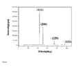
- the X-ray diffraction spectrum for the matte side of the electrolytic copper foil obtained in Examples 1 to 4 and Comparative Examples 1 to 4 was measured.
- the XRD spectrum for Example 1 was shown in FIG. 6 .
- the peak intensity of the (111) crystal face is highest and the (200) crystal face has the second highest peak intensity.
- the I(200)/I(111) which is the ratio of the intensity (I(200)) of the diffraction peak for the (200) crystal face and the intensity (I(111)) of the diffraction peak for the (111) crystal face was 0.605.
- orientation index M for the (111), (200), (220), (311), (222) crystal faces was measured in the XRD spectrum for the matte side and the measured result was shown in the following Table 3.
- the orientation index was measured by the orientation index (M) which is proposed in S.Yoshimura, S. Yoshihara, T.Shirakashi, E.Sato, Electrochim. Acta 39, 589(1994 ).
- the orientation index (M) is calculated by the following method.
- IFR 111 IF 111 / IF 111 + IF 200 + IF 220 + IF 311
- the IF (111) is the XRD intensity in JCPDS cards and the I(111) is an experiment value.
- the M(200)/M(111) which is the ratio of the orientation index (M(200)) for the (200) crystal face in the XRD spectrum for the matte side and the orientation index obtained from the orientation index (M(111)) for the (111) crystal face was 1.31.
- the surface roughness Rz and Ra of the matte side and the shiny side of the electrolytic copper foil obtained in Examples 1 to 4 and Comparative Examples 1 to 4 were measured by JISB 0601-1994 standard.
- the surface roughness Rz and Ra obtained by the measurement method were shown in the following Table 4. The lower the value, the lower the roughness.
- Evaluation Example 5 Measurement of tensile strength at room temperature, elongation at room temperature, tensile strength at high temperature, and elongation at high temperature
- the maximum load of the tensile strength measured by acquiring a tensile sample 12.7 mm in width x 50 mm in gauge length and then performing a tensile test at a crosshead speed of 50.8 mm/min using IPC-TM-650 2.4.18B standard was called the tensile strength at room temperature and the elongation at the time of fracture was called the elongation at room temperature.
- the room temperature is 25 °C.
- the same electrolytic copper foil as the electrolytic copper foil which was used to measure the tensile strength and the elongation at room temperature was heat treated at 180 °C for 1 hour and was taken out and then the tensile strength and the elongation of the electrolytic copper foil were measured, which was called the tensile strength and the elongation at high temperature.
- the electrolytic copper foil in Examples 1 to 4 has the surface roughness Rz lower than 0.5 ⁇ m, and after the electrolytic copper foil is heat treated at high temperature, the tensile strength of the electrolytic copper foil is equal to or more than 40 kgf/mm 2 and after the electrolytic copper foil is heat treated at high temperature, most of the elongation thereof is equal to or more than 10 %.
- the electrolytic copper foil of Comparative Examples 1 to 4 has the surface roughness higher than that of Examples 1 to 4 and after the electrolytic copper foil is heat treated at high temperature, the elongation of the electrolytic copper foil is low and therefore the electrolytic copper foil is inappropriate for the cathode current collector for the secondary battery and/or the low-roughness copper foil for the PDB/FPC.
- the corner curl angle of the electrolytic copper foil of Examples 1 to 4 was equal to or less than 45° as 5 to 30°.
- the corner curl angle of the electrolytic copper foil of Comparative Examples 1 to 4 exceeds 45° as 46° to 52° and therefore the electrolytic copper foil may not be easily handled in the subsequent process.
- the corner curl height of the electrolytic copper foil of Comparative Examples 1 to 4 exceeds 40 mm and thus the quality of the electrolytic copper foil was poor. Therefore, the electrolytic copper foil according to the exemplary embodiment of the present invention has the high strength but has the reduced internal stress to make the corner curling phenomenon less appear, and as a result, has excellent performance.
- the size and the density of the pore between the surface elements protruding outwardly from the matte side are relatively small and thus the high glossiness appears even before the post-processing process, thereby improving the product quality.
- the electrolytic copper foil has the reduced stress inside the electrolytic copper foil while having the high strength and the high elongation to prevent the corner curling phenomenon.
- the electrolytic copper foil has the low roughness, the high strength, and the high elongation to facilitate the process performance and reduce the product defective rate, and the electrolytic copper foil is used in products such as the PCB and the cathode current collector of the secondary battery to improve the product reliability.
Landscapes
- Chemical & Material Sciences (AREA)
- Engineering & Computer Science (AREA)
- Chemical Kinetics & Catalysis (AREA)
- Electrochemistry (AREA)
- Materials Engineering (AREA)
- Metallurgy (AREA)
- Organic Chemistry (AREA)
- General Chemical & Material Sciences (AREA)
- Cell Electrode Carriers And Collectors (AREA)
Priority Applications (1)
| Application Number | Priority Date | Filing Date | Title |
|---|---|---|---|
| EP15158190.7A EP3067442A1 (fr) | 2015-03-09 | 2015-03-09 | Film de cuivre électrolytique, composant électrique et batterie comprenant celle-ci |
Applications Claiming Priority (1)
| Application Number | Priority Date | Filing Date | Title |
|---|---|---|---|
| EP15158190.7A EP3067442A1 (fr) | 2015-03-09 | 2015-03-09 | Film de cuivre électrolytique, composant électrique et batterie comprenant celle-ci |
Publications (1)
| Publication Number | Publication Date |
|---|---|
| EP3067442A1 true EP3067442A1 (fr) | 2016-09-14 |
Family
ID=52684015
Family Applications (1)
| Application Number | Title | Priority Date | Filing Date |
|---|---|---|---|
| EP15158190.7A Withdrawn EP3067442A1 (fr) | 2015-03-09 | 2015-03-09 | Film de cuivre électrolytique, composant électrique et batterie comprenant celle-ci |
Country Status (1)
| Country | Link |
|---|---|
| EP (1) | EP3067442A1 (fr) |
Cited By (5)
| Publication number | Priority date | Publication date | Assignee | Title |
|---|---|---|---|---|
| TWI614933B (zh) * | 2016-11-11 | 2018-02-11 | 日進材料股份有限公司 | 用於具有優異之可撓性電阻之二次電池的電解銅箔及製造彼之方法 |
| CN110016697A (zh) * | 2019-05-22 | 2019-07-16 | 青海电子材料产业发展有限公司 | 一种制备高温高延伸率动力电池用电解铜箔的方法及其添加剂 |
| JP2020125540A (ja) * | 2019-02-01 | 2020-08-20 | 長春石油化學股▲分▼有限公司 | リチウムイオン二次電池の負極集電体に用いられる銅箔 |
| CN111670269A (zh) * | 2018-02-01 | 2020-09-15 | Kcf技术有限公司 | 具有高温尺寸稳定性和织构稳定性的电解铜箔及其制造方法 |
| CN115838948A (zh) * | 2022-12-09 | 2023-03-24 | 安徽华创新材料股份有限公司 | 一种铜箔加工用无胶原蛋白添加剂及铜箔加工工艺 |
Citations (1)
| Publication number | Priority date | Publication date | Assignee | Title |
|---|---|---|---|---|
| KR101478464B1 (ko) * | 2013-10-14 | 2015-01-02 | 일진머티리얼즈 주식회사 | 전해동박, 이를 포함하는 전기부품 및 전지 |
-
2015
- 2015-03-09 EP EP15158190.7A patent/EP3067442A1/fr not_active Withdrawn
Patent Citations (1)
| Publication number | Priority date | Publication date | Assignee | Title |
|---|---|---|---|---|
| KR101478464B1 (ko) * | 2013-10-14 | 2015-01-02 | 일진머티리얼즈 주식회사 | 전해동박, 이를 포함하는 전기부품 및 전지 |
Cited By (12)
| Publication number | Priority date | Publication date | Assignee | Title |
|---|---|---|---|---|
| TWI614933B (zh) * | 2016-11-11 | 2018-02-11 | 日進材料股份有限公司 | 用於具有優異之可撓性電阻之二次電池的電解銅箔及製造彼之方法 |
| CN111670269A (zh) * | 2018-02-01 | 2020-09-15 | Kcf技术有限公司 | 具有高温尺寸稳定性和织构稳定性的电解铜箔及其制造方法 |
| US11346015B2 (en) | 2018-02-01 | 2022-05-31 | Kcf Technologies Co., Ltd. | Electrolytic copper foil having high-temperature dimensional stability and texture stability, and manufacturing method therefor |
| JP2020125540A (ja) * | 2019-02-01 | 2020-08-20 | 長春石油化學股▲分▼有限公司 | リチウムイオン二次電池の負極集電体に用いられる銅箔 |
| US10772199B2 (en) | 2019-02-01 | 2020-09-08 | Chang Chun Petrochemical Co., Ltd. | Low transmission loss copper foil and methods for manufacturing the copper foil |
| US10787751B2 (en) | 2019-02-01 | 2020-09-29 | Chang Chun Petrochemical Co., Ltd. | Electrolytic copper foil with low profile |
| US11145867B2 (en) | 2019-02-01 | 2021-10-12 | Chang Chun Petrochemical Co., Ltd. | Surface treated copper foil |
| US11283080B2 (en) | 2019-02-01 | 2022-03-22 | Chang Chun Petrochemical Co., Ltd. | Electrodeposited copper foil, current collector, electrode, and lithium ion secondary battery comprising the same |
| US11362337B2 (en) | 2019-02-01 | 2022-06-14 | Chang Chun Petrochemical Co., Ltd. | Electrodeposited copper foil and electrode, and lithium-ion secondary battery comprising the same |
| CN110016697A (zh) * | 2019-05-22 | 2019-07-16 | 青海电子材料产业发展有限公司 | 一种制备高温高延伸率动力电池用电解铜箔的方法及其添加剂 |
| CN110016697B (zh) * | 2019-05-22 | 2020-10-23 | 青海电子材料产业发展有限公司 | 一种制备高温高延伸率动力电池用电解铜箔的方法及其添加剂 |
| CN115838948A (zh) * | 2022-12-09 | 2023-03-24 | 安徽华创新材料股份有限公司 | 一种铜箔加工用无胶原蛋白添加剂及铜箔加工工艺 |
Similar Documents
| Publication | Publication Date | Title |
|---|---|---|
| US9899683B2 (en) | Electrolytic copper foil, electric component and battery including the same | |
| EP3067199B1 (fr) | Cuivre électrodéposé ainsi que composant électrique et batterie comprenant celui-ci | |
| KR101605071B1 (ko) | 전해도금에 의한 구리호일 | |
| JP6014186B2 (ja) | 電解銅箔、これを含む電気部品および電池 | |
| US9562298B2 (en) | Electrodeposited copper foil | |
| US7789976B2 (en) | Low surface roughness electrolytic copper foil and process for producing the same | |
| TWI504764B (zh) | 電解銅箔、包含該箔的電氣組件和電池及其製備方法 | |
| KR101571060B1 (ko) | 전해동박, 이를 포함하는 전기부품 및 전지, 및 전해동박 제조방법 | |
| EP3067442A1 (fr) | Film de cuivre électrolytique, composant électrique et batterie comprenant celle-ci | |
| KR101571064B1 (ko) | 전해동박, 이를 포함하는 전기부품 및 전지, 및 전해동박 제조방법 | |
| JP6595548B2 (ja) | 電解銅箔、電解銅箔の製造方法、電池の集電体、及び回路基板 | |
| CN105986288A (zh) | 电解铜箔、包含该电解铜箔的电气部件及电池 | |
| KR101571063B1 (ko) | 전해동박, 이를 포함하는 전기부품 및 전지, 및 전해동박 제조방법 | |
| WO2014061983A9 (fr) | Feuille de cuivre électrolytique, pièce électrique et batterie comprenant cette feuille de cuivre électrolytique et procédé permettant de fabriquer cette feuille de cuivre électrolytique | |
| KR101502373B1 (ko) | 전해동박, 이를 포함하는 전기부품 및 전지 | |
| KR101571066B1 (ko) | 전해동박, 이를 포함하는 전기부품 및 전지, 및 전해동박 제조방법 | |
| KR101478464B1 (ko) | 전해동박, 이를 포함하는 전기부품 및 전지 | |
| KR102681509B1 (ko) | 이중층 전해동박 및 그 제조방법 | |
| TWI643982B (zh) | 電解銅箔,包含該銅箔之電氣組件及電池 | |
| EP4424883A1 (fr) | Feuille de cuivre électrolytique pour collecteur de courant de batterie secondaire | |
| EP4424882A1 (fr) | Feuille de cuivre électrolytique pour collecteur de courant de batterie secondaire | |
| EP4446476A1 (fr) | Feuille de cuivre électrolytique présentant des caractéristiques de résistance et d'allongement élevées |
Legal Events
| Date | Code | Title | Description |
|---|---|---|---|
| PUAI | Public reference made under article 153(3) epc to a published international application that has entered the european phase |
Free format text: ORIGINAL CODE: 0009012 |
|
| 17P | Request for examination filed |
Effective date: 20150309 |
|
| AK | Designated contracting states |
Kind code of ref document: A1 Designated state(s): AL AT BE BG CH CY CZ DE DK EE ES FI FR GB GR HR HU IE IS IT LI LT LU LV MC MK MT NL NO PL PT RO RS SE SI SK SM TR |
|
| AX | Request for extension of the european patent |
Extension state: BA ME |
|
| STAA | Information on the status of an ep patent application or granted ep patent |
Free format text: STATUS: THE APPLICATION IS DEEMED TO BE WITHDRAWN |
|
| 18D | Application deemed to be withdrawn |
Effective date: 20170315 |