EP3067490A1 - Schliessblech für einen treibstangenbeschlag - Google Patents
Schliessblech für einen treibstangenbeschlag Download PDFInfo
- Publication number
- EP3067490A1 EP3067490A1 EP16153995.2A EP16153995A EP3067490A1 EP 3067490 A1 EP3067490 A1 EP 3067490A1 EP 16153995 A EP16153995 A EP 16153995A EP 3067490 A1 EP3067490 A1 EP 3067490A1
- Authority
- EP
- European Patent Office
- Prior art keywords
- cover plate
- plate
- spring element
- base body
- striker
- Prior art date
- Legal status (The legal status is an assumption and is not a legal conclusion. Google has not performed a legal analysis and makes no representation as to the accuracy of the status listed.)
- Granted
Links
Images


Classifications
-
- E—FIXED CONSTRUCTIONS
- E05—LOCKS; KEYS; WINDOW OR DOOR FITTINGS; SAFES
- E05B—LOCKS; ACCESSORIES THEREFOR; HANDCUFFS
- E05B15/00—Other details of locks; Parts for engagement by bolts of fastening devices
- E05B15/02—Striking-plates; Keepers; Bolt staples; Escutcheons
- E05B15/0205—Striking-plates, keepers, staples
- E05B15/022—Striking-plates, keepers, staples movable, resilient or yieldable
-
- E—FIXED CONSTRUCTIONS
- E05—LOCKS; KEYS; WINDOW OR DOOR FITTINGS; SAFES
- E05C—BOLTS OR FASTENING DEVICES FOR WINGS, SPECIALLY FOR DOORS OR WINDOWS
- E05C9/00—Arrangements of simultaneously actuated bolts or other securing devices at well-separated positions on the same wing
- E05C9/18—Details of fastening means or of fixed retaining means for the ends of bars
- E05C9/1808—Keepers
-
- E—FIXED CONSTRUCTIONS
- E05—LOCKS; KEYS; WINDOW OR DOOR FITTINGS; SAFES
- E05B—LOCKS; ACCESSORIES THEREFOR; HANDCUFFS
- E05B15/00—Other details of locks; Parts for engagement by bolts of fastening devices
- E05B15/04—Spring arrangements in locks
- E05B2015/0458—Leaf springs; Non-wound wire springs
Definitions
- Striker plate for an espagnolette fitting of a wing of a window, a French window or the like which can be pivoted against a frame with a base body and with a cover plate connected to the base body, with a recess in the cover plate for receiving a bolt of the espagnolette fitting, with a guide element prestressed by a spring element Guide the bolt and with adjusting means for adjusting the position of the guide element relative to the main body.
- Such a striking plate is for example from the EP 2 762 660 A2 known.
- a cup-shaped guide element via an eccentric relative to the cover plate is adjustable.
- the eccentric is supported by spring elements on the base body.
- the position of the guide element can be adjusted relative to the bolt.
- the spring elements allow tolerance compensation. Due to the arrangement of the eccentric between the guide element and the spring element, however, the strike plate has a very large frictional resistance.
- the WO 2009/125436 A1 discloses a planar strike plate in which a bow-shaped spring wire projects directly into a recess of a flat plate. The compared to the recess very thin spring wire can twist while sliding along the bolt. Thus, the exact determination of a biasing force by the spring element is not possible. A basic body for safe positive connection with the frame or the wing is not provided.
- a strike plate has become known in which a guide element for guiding the bolt is tiltably arranged in a base body.
- a trained as a coil spring spring element biases the guide member against the located in the closed position latch.
- the invention is based on the problem, so far as to form a strike plate of the type mentioned that it allows the introduction of high forces in the frame or the wing and allows the most accurate determination of the biasing force of the bolt.
- the spring element has the shape of a ramp leading the ramp and that the ramp projects directly into the recess.
- the spring element is formed by the shape of the ramp as a guide element and protrudes for immediate support of the bolt in the locked position of the espagnolette fitting in the recess.
- friction between the guide element and the spring element is excluded.
- the spring element by the shape of the ramp also allows a uniformly increasing bias of the bolt in the locking of the espagnolette fitting. Through this design can be first move the espagnolette fitting smoothly. In the locked position, however, the bolt receives the maximum bias, so that the wing is reliably pulled against the frame.
- the body can be a particularly high stability of the striking plate with the wing or the frame produce.
- a one-piece production of the spring element with the ramp designed according to an advantageous embodiment of the invention is particularly simple when the spring element is a spring plate.
- the assembly of the bolt is particularly simple according to another advantageous embodiment of the invention, when the spring element is arranged on a holding element connected to the cover plate.
- the spring element is supported on the retaining element and therefore allows high holding forces of the striking plate.
- the spring element is held reliably according to another advantageous embodiment of the invention in its intended position when the spring element has at least one penetrating into a pocket of the holding member section.
- the spring element is arranged according to another advantageous embodiment of the invention close to the recess of the cover plate and therefore able to lead the bolt early when the spring element is clamped between the cover plate and the holding element.
- Another advantage of this design is the particularly simple assembly and mounting of the spring element.
- the adjustment of the bias of the bolt relative to the strike plate designed according to another advantageous embodiment of the invention is particularly simple when the actuating means have an actuating device with at least one eccentric.
- the means for adjusting the cover plate relative to the base body may optionally have a slot in a screw or an eccentric.
- the base body is designed pot-shaped for the positive reception of the retaining element.
- the strike plate according to another advantageous embodiment of the invention has a particularly high stability when at least one of the components of the main body or of the holding element has a recess corresponding to the recess in the cover plate.
- the strike plate offers a particularly high level of protection against a break-open attempt of the espagnolette fitting.
- it contributes according to another advantageous embodiment of the invention, when holes for screwing the body are inclined in a frame or wing to the plane of the cover plate. This inclined arrangement of the holes allows the introduction of particularly high forces in the wing or the frame.
- FIG. 1 schematically shows a window / a door with a pivotable against a frame 1 wings 2 and with a drive rod fitting 3.
- the espagnolette fitting 3 has a main lock 4 and several via a drive rod fifth
- the secondary locks 6 have a retractable from the wing 2 latch 7, which engages in a locked position in a arranged in the frame 1 strike plate 8.
- FIG. 2 shows enlarged in a sectional view through one of the secondary locks 6, the latch 7 and the striking plate 8 in the locked position.
- the striking plate 8 has a base body 9 fixed in the frame 1 with a cover plate 10. Between the cover plate 10 and the base body 9, a retaining element 11 and a spring element 12 are arranged.
- the spring element 12 is formed as a spring plate and has the shape of a bolt 7 leading to the ramp 13.
- the spring element 12 forms with the ramp 13, a guide member 14 for guiding the bolt 7.
- exerted by the spring member 12 on the bolt 7 bias one provided suit of in FIG. 1 shown wing 2 against the frame 1 safely.
- FIG. 3 shows in a perspective view of the strike plate 8 FIG. 2 with the latch 7, that the cover plate 10 has a recess 15 for the latch 7.
- the striking plate 8 is shown in a longitudinal section.
- the oblong holes thus form adjusting means for adjusting the height of the cover plate 10 relative to the base body 9.
- the latch 7 thus reliably engages behind the region of the cover plate 10 adjacent to the recess 15.
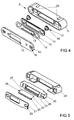
- FIG. 4 shows an exploded view of the components of the striking plate 8.
- the holding member 11 can be adjusted via an adjusting device 17 with an eccentric 18 relative to the cover plate 10.
- the adjustment of the Retaining element 11 via the adjusting device 17 is arranged orthogonal to the adjustment by the slots 16 of the screw connection of the cover plate 10.
- the main body 9 has transverse to the plane of the cover plate 10 extending holes 19 for screwing to the frame 1 FIG. 1 ,
- FIG. 5 shows a further embodiment of the closing plate 8 with a base 20 of a cover plate 21 a spring element 22 and a holding element 23.
- the holding member 23 has a pocket 24 for receiving a portion 25 of the spring element 22.
- the spring element 22 has as the embodiment of the embodiment FIG. 4 a ramp 26 for the latch 7 and is thus made in one piece with a guide element 27.
- the holding element 23 has slots 28 for screwing to the base body 20.
- the elongated holes 28 in the holding element 23 are arranged orthogonal to slots 29 of the cover plate 21.
- the elongated holes 28, 29 serve as adjusting means for adjustability of the components in their screw connection to the base body 20th
Landscapes
- Engineering & Computer Science (AREA)
- Mechanical Engineering (AREA)
- Lock And Its Accessories (AREA)
- Closing And Opening Devices For Wings, And Checks For Wings (AREA)
Abstract
Description
- Schließblech für einen Treibstangenbeschlag eines gegen einen Rahmen schwenkbaren Flügels eines Fenster, einer Fenstertür oder dergleichen mit einem Grundkörper und mit einer mit dem Grundkörper verbundenen Deckplatte, mit einer Ausnehmung in der Deckplatte zur Aufnahme eines Riegels des Treibstangenbeschlages, mit einem von einem Federelement vorgespannten Führungselement zur Führung des Riegels und mit Stellmitteln zur Verstellung der Position des Führungselementes gegenüber dem Grundkörper.
- Ein solches Schließblech ist beispielsweise aus der
EP 2 762 660 A2 bekannt. Bei diesem Schließblech ist ein becherförmiges Führungselement über einen Exzenter gegenüber dem Deckblech verstellbar. Der Exzenter stützt sich über Federelemente an dem Grundkörper ab. Über den Exzenter lässt sich die Position des Führungselementes gegenüber dem Riegel einstellen. Bei einem Eindringen des Riegels des Treibstangenbeschlages ermöglichen die Federelemente einen Toleranzausgleich. Durch die Anordnung des Exzenters zwischen dem Führungselement und dem Federelement hat das Schließblech jedoch einen sehr großen Reibungswiderstand. - Die
WO 2009/125436 A1 offenbart ein ebenes Schließblech, bei dem ein bügelförmiger Federdraht unmittelbar in eine Ausnehmung einer ebenen Platte hineinragt. Der im Vergleich zur Ausnehmung sehr dünne Federdraht kann sich beim Entlanggleiten des Riegels verdrehen. Damit ist die genaue Festlegung einer Vorspannkraft durch das Federelement nicht möglich. Ein Grundkörper zur sicheren formschlüssigen Verbindung mit dem Rahmen oder dem Flügel ist nicht vorgesehen. - Aus der
EP 2 447 452 A1 ist ein Schließblech bekannt geworden, bei dem ein Führungselement zur Führung des Riegels kippbar in einem Grundkörper angeordnet ist. Ein als Wendelfeder ausgebildetes Federelement spannt das Führungselement gegen den in Schließstellung befindlichen Riegel vor. Damit weist die Lagerung des Führungselementes im Grundkörper einen Reibungswiderstand auf, welcher eine genaue Festlegung einer Vorspannkraft durch das Federelement verhindert. - Der Erfindung liegt das Problem zugrunde, ein Schließblech der eingangs genannten Art so weiter zu bilden, dass es die Einleitung hoher Kräfte in den Rahmen oder den Flügel ermöglicht und die besonders genaue Festlegung der Vorspannkraft des Riegels ermöglicht.
- Dieses Problem wird erfindungsgemäß dadurch gelöst, dass das Federelement die Form einer den Riegel führenden Rampe hat und dass die Rampe unmittelbar in die Ausnehmung hineinragt.
- Durch diese Gestaltung ist das Federelement durch die Formgebung der Rampe als Führungselement ausgebildet und ragt zur unmittelbaren Abstützung des Riegels in der verriegelten Stellung des Treibstangenbeschlages in die Ausnehmung hinein. Durch diese einstückige Gestaltung wird eine Reibung zwischen dem Führungselement und dem Federelement ausgeschlossen. Damit ermöglicht diese Gestaltung die genaue Festlegung der Vorspannkraft des Riegels. Weiterhin ermöglicht das Federelement durch die Formgebung der Rampe zudem eine gleichmäßig ansteigende Vorspannung des Riegels bei der Verriegelung des Treibstangenbeschlages. Durch diese Gestaltung lässt sich der Treibstangenbeschlag zunächst leichtgängig bewegen. In verriegelter Stellung erhält der Riegel jedoch die maximale Vorspannung, so dass der Flügel zuverlässig gegen den Rahmen gezogen wird. Durch den Grundkörper lässt sich eine besonders hohe Stabilität des Schließblechs mit dem Flügel oder dem Rahmen erzeugen.
- Eine einstückige Fertigung des Federelementes mit der Rampe gestaltet sich gemäß einer vorteilhaften Weiterbildung der Erfindung besonders einfach, wenn das Federelement ein Federblech ist.
- Die Montage des Riegels gestaltet sich gemäß einer anderen vorteilhaften Weiterbildung der Erfindung besonders einfach, wenn das Federelement auf einem mit der Deckplatte verbundenen Halteelement angeordnet ist. Durch diese Gestaltung stützt sich das Federelement an das Halteelement ab und ermöglicht daher hohe Haltekräfte des Schließblechs.
- Das Federelement ist gemäß einer anderen vorteilhaften Weiterbildung der Erfindung in seiner vorgesehenen Lage zuverlässig gehalten, wenn das Federelement zumindest einen in eine Tasche des Halteelements eindringendes Teilstück hat.
- Das Federelement ist gemäß einer anderen vorteilhaften Weiterbildung der Erfindung nahe an der Ausnehmung der Deckplatte angeordnet und vermag daher den Riegel frühzeitig zu führen, wenn das Federelement zwischen der Deckplatte und dem Halteelement eingespannt ist. Ein weiterer Vorteil dieser Gestaltung besteht in der besonders einfachen Montage und Halterung des Federelementes.
- Einbautoleranzen des Treibstangenbeschlages lassen sich gemäß einer anderen vorteilhaften Weiterbildung der Erfindung zuverlässig ausgleichen, wenn die Stellmittel zur Verstellung des Halteelements gegenüber der Deckplatte vorgesehen sind und wenn weitere Stellmittel zur Verstellung der Deckplatte gegenüber dem Grundkörper vorgesehen sind, wobei die Verstellrichtungen der Stellmittel orthogonal zueinander angeordnet sind. Durch diese Gestaltung lassen sich besonders einfach über die Stellmittel die Höhe der Ausnehmung und über die Mittel zur Verstellung die Vorspannung des Riegels an dem Schließblech und damit der Anzug des Flügels gegen den Rahmen verstellen.
- Die Verstellung der Vorspannung des Riegels gegenüber dem Schließblech gestaltet sich gemäß einer anderen vorteilhaften Weiterbildung der Erfindung besonders einfach, wenn die Stellmittel eine Stelleinrichtung mit zumindest einem Exzenter haben. Die Mittel zur Verstellung der Deckplatte gegenüber dem Grundkörper können wahlweise ein Langloch in einer Verschraubung oder einen Exzenter aufweisen.
- Zur weiteren Erhöhung der Stabilität des Schließblechs trägt es gemäß einer anderen vorteilhaften Weiterbildung der Erfindung bei, wenn der Grundkörper topfförmig zur formschlüssigen Aufnahme des Halteelements gestaltet ist.
- Das Schließblech hat gemäß einer anderen vorteilhaften Weiterbildung der Erfindung eine besonders hohe Stabilität, wenn zumindest eines der Bauteile des Grundkörpers oder des Halteelements eine der Ausnehmung in der Deckplatte entsprechende Ausnehmung hat. Damit bietet das Schließblech einen besonders hohen Schutz gegen einen Aufbruchsversuch des Treibstangenbeschlages. Zur weiteren Erhöhung der Stabilität des Schließblechs im montierten Zustand trägt es gemäß einer anderen vorteilhaften Weiterbildung der Erfindung bei, wenn Bohrungen zur Verschraubung des Grundkörpers in einem Rahmen oder Flügel zu der Ebene der Deckplatte geneigt sind. Diese geneigte Anordnung der Bohrungen ermöglicht die Einleitung besonders hoher Kräfte in den Flügel oder den Rahmen.
- Die Erfindung lässt zahlreiche Ausführungsformen zu. Zur weiteren Verdeutlichung ihres Grundprinzips sind zwei davon in der Zeichnung dargestellt und werden nachfolgend beschrieben. Diese zeigt in
- Fig. 1
- ein Fenster/eine Tür mit einem Treibstangenbeschlag,
- Fig. 2
- vergrößert eine Schnittdarstellung durch einen Teilbereich des Treibstangenbeschlages mit einem erfindungsgemäßen Schließblech,
- Fig. 3
- eine weitere Schnittdarstellung des Teilbereichs aus
Figur 2 - Fig. 4
- eine Explosionsdarstellung von Bauteilen des erfindungsgemäßen Schließblechs aus
Figur 2 , - Fig. 5
- eine Explosionsdarstellung einer weiteren Ausführungsform des Schließblechs.
-
Figur 1 zeigt schematisch ein Fenster/eine Tür mit einem gegen einen Rahmen 1 schwenkbaren Flügel 2 und mit einem Treibstangenbeschlag 3. Der Treibstangenbeschlag 3 hat ein Hauptschloss 4 und mehrere über eine Treibstange 5 von dem Hauptschloss 4 antreibbare Nebenschlösser 6. Die Nebenschlösser 6 haben einen aus dem Flügel 2 ausfahrbaren Riegel 7, der in einer verriegelten Stellung in ein im Rahmen 1 angeordnetes Schließblech 8 eingreift. -
Figur 2 zeigt vergrößert in einer Schnittdarstellung durch eines der Nebenschlösser 6 den Riegel 7 und das Schließblech 8 in verriegelter Stellung. Das Schließblech 8 hat einen im Rahmen 1 befestigten Grundkörper 9 mit einer Deckplatte 10. Zwischen der Deckplatte 10 und dem Grundkörper 9 ist ein Halteelement 11 und ein Federelement 12 angeordnet. Das Federelement 12 ist als Federblech ausgebildet und hat die Form einer den Riegel 7 führenden Rampe 13. Das Federelement 12 bildet mit der Rampe 13 ein Führungselement 14 zur Führung des Riegels 7. Gleichzeitig stellt die von dem Federelement 12 auf den Riegel 7 ausgeübte Vorspannung einen vorgesehenen Anzug des inFigur 1 dargestellten Flügels 2 gegen den Rahmen 1 sicher. -
Figur 3 zeigt in einer perspektivischen Darstellung auf das Schließblech 8 ausFigur 2 mit dem Riegel 7, dass die Deckplatte 10 eine Ausnehmung 15 für den Riegel 7 hat. Zur Verdeutlichung ist das Schließblech 8 in einem Längsschnitt dargestellt. Eine Verschraubung der Deckplatte 10 mit dem Grundkörper 9 hat Langlöcher 16. Die Langlöcher bilden hierdurch Stellmittel zur Verstellung der Höhe der Deckplatte 10 gegenüber dem Grundkörper 9. Der Riegel 7 hintergreift damit zuverlässig den an die Ausnehmung 15 angrenzenden Bereich der Deckplatte 10. -
Figur 4 zeigt eine Explosionsdarstellung der Bauteile des Schließblechs 8. Das Halteelement 11 lässt sich über eine Stelleinrichtung 17 mit einem Exzenter 18 gegenüber der Deckplatte 10 verstellen. Die Verstellrichtung des Halteelements 11 über die Stelleinrichtung 17 ist orthogonal zur Verstellrichtung durch die Langlöcher 16 der Verschraubung der Deckplatte 10 angeordnet. Mittels der Stelleinrichtung 17 lässt sich die Position des Führungselementes 14 des Federelementes 12 und damit die Vorspannung gegen den Riegel 7 verstellen. Der Grundkörper 9 hat quer zur Ebene der Deckplatte 10 verlaufende Bohrungen 19 zur Verschraubung mit dem Rahmen 1 ausFigur 1 . -
Figur 5 zeigt eine weitere Ausbildungsform des Schließblechs 8 mit einem Grundkörper 20 einer Deckplatte 21 einem Federelement 22 und einem Halteelement 23. Das Halteelement 23 hat eine Tasche 24 zur Aufnahme eines Teilstücks 25 des Federelementes 22. Das Federelement 22 hat wie das aus der Ausführungsform nachFigur 4 eine Rampe 26 für den Riegel 7 und ist damit einstückig mit einem Führungselement 27 gefertigt. Das Halteelement 23 hat Langlöcher 28 zur Verschraubung mit dem Grundkörper 20. Die Langlöcher 28 in dem Halteelement 23 sind orthogonal zu Langlöchern 29 der Deckpatte 21 angeordnet. Die Langlöcher 28, 29 dienen als Stellmittel zur Verstellbarkeit der Bauteile bei ihrer Verschraubung mit dem Grundkörper 20.
Claims (10)
- Schließblech (8) für einen Treibstangenbeschlag (3) eines gegen einen Rahmen (1) schwenkbaren Flügels (2) eines Fenster, einer Fenstertür oder dergleichen mit einem Grundkörper (9, 20) und mit einer mit dem Grundkörper (9, 20) verbundenen Deckplatte (10, 21), mit einer Ausnehmung (15) in der Deckplatte (10, 21) zur Aufnahme eines Riegels (7) des Treibstangenbeschlages (3), mit einem von einem Federelement (12, 22) vorgespannten Führungselement (14, 27) zur Führung des Riegels (7) und mit Stellmitteln zur Verstellung der Position des Führungselementes (14, 27) gegenüber dem Grundkörper (9, 20), dadurch gekennzeichnet, dass das Federelement (12, 22) die Form einer den Riegel (7) führenden Rampe (13, 26) hat und dass die Rampe (13, 26) unmittelbar in die Ausnehmung (15) hineinragt.
- Schließblech nach Anspruch 1, dadurch gekennzeichnet, dass das Federelement (12, 22) ein Federblech ist.
- Schließblech nach Anspruch 1 oder 2, dadurch gekennzeichnet, dass das Federelement (12, 22) auf einem mit der Deckplatte (10, 21) verbundenen Halteelement (11, 23) angeordnet ist.
- Schließblech nach einem der Ansprüche 1 bis 3, dadurch gekennzeichnet, dass das Federelement (22) zumindest einen in eine Tasche (24) des Halteelements (23) eindringendes Teilstück (25) hat.
- Schließblech nach einem der Ansprüche 1 bis 4, dadurch gekennzeichnet, dass das Federelement (12, 22) zwischen der Deckplatte (10, 21) und dem Halteelement (11, 23) eingespannt ist.
- Schließblech nach einem der Ansprüche 1 bis 5, dadurch gekennzeichnet, dass die Stellmittel zur Verstellung des Halteelements (11, 23) gegenüber der Deckplatte (10, 21) vorgesehen sind und dass weitere Stellmittel zur Verstellung der Deckplatte (10, 21) gegenüber dem Grundkörper (9, 20) vorgesehen sind, wobei die Verstellrichtungen der Stellmittel orthogonal zueinander angeordnet sind.
- Schließblech nach einem der Ansprüche 1 bis 6, dadurch gekennzeichnet, dass die Stellmittel eine Stelleinrichtung (17) mit zumindest einen Exzenter (18) haben.
- Schließblech nach einem der Ansprüche 1 bis 7, dadurch gekennzeichnet, dass der Grundkörper (9, 20) topfförmig zur formschlüssigen Aufnahme des Halteelements (11, 23) gestaltet ist.
- Schließblech nach einem der Ansprüche 1 bis 8, dadurch gekennzeichnet, dass zumindest eines der Bauteile des Grundkörpers (9, 20) oder des Halteelements (11, 23) eine der Ausnehmung (15) in der Deckplatte (10, 21) entsprechende Ausnehmung hat.
- Schließblech nach einem der Ansprüche 1 bis 9, dadurch gekennzeichnet, dass Bohrungen (19) zur Verschraubung des Grundkörpers (9, 20) in einem Rahmen (1) oder Flügel (2) zu der Ebene der Deckplatte (10, 21) geneigt sind.
Applications Claiming Priority (1)
| Application Number | Priority Date | Filing Date | Title |
|---|---|---|---|
| DE102015204508.0A DE102015204508A1 (de) | 2015-03-12 | 2015-03-12 | Schließblech für einen Treibstangenbeschlag |
Publications (2)
| Publication Number | Publication Date |
|---|---|
| EP3067490A1 true EP3067490A1 (de) | 2016-09-14 |
| EP3067490B1 EP3067490B1 (de) | 2018-04-18 |
Family
ID=55300398
Family Applications (1)
| Application Number | Title | Priority Date | Filing Date |
|---|---|---|---|
| EP16153995.2A Active EP3067490B1 (de) | 2015-03-12 | 2016-02-03 | Schliessblech für einen treibstangenbeschlag |
Country Status (2)
| Country | Link |
|---|---|
| EP (1) | EP3067490B1 (de) |
| DE (1) | DE102015204508A1 (de) |
Cited By (2)
| Publication number | Priority date | Publication date | Assignee | Title |
|---|---|---|---|---|
| DE102016120657A1 (de) * | 2016-10-28 | 2018-05-03 | Gretsch-Unitas GmbH Baubeschläge | Vorrichtung zur Aufnahme eines Fallenriegels und Verriegelungsvorrichtung zur Verriegelung eines Türflügels |
| EP4336000A1 (de) * | 2022-09-12 | 2024-03-13 | Roto Frank Fenster- und Türtechnologie GmbH | Schliessstück für eine schwellenleistenanordnung einer gebäudeverschlusseinrichtung, entsprechende schwellenleistenanordnung sowie verfahren zum montieren eines schliessstücks |
Citations (10)
| Publication number | Priority date | Publication date | Assignee | Title |
|---|---|---|---|---|
| DE2921201A1 (de) * | 1978-06-09 | 1979-12-13 | Hrachowina Bauelemente Prod | Schliesstueck fuer zungenverschluesse von fenstern oder tueren |
| EP1113129A1 (de) * | 1999-12-23 | 2001-07-04 | Picard | Einstellbares Schliessblech für ein Schloss |
| EP1113127A1 (de) * | 1999-12-30 | 2001-07-04 | KARL FLIETHER GmbH & Co. | Schliessblech |
| EP1413697A2 (de) * | 2002-10-25 | 2004-04-28 | Epwin Group Plc | Schliessblech und Schlosssystem bzw. Schliessblech für ein Schloss |
| DE10328330A1 (de) * | 2003-06-24 | 2005-01-20 | Baugruppentechnik Pollmeier Gmbh | Schließblech mit Federungsabschnitt |
| WO2009125436A1 (en) | 2008-04-08 | 2009-10-15 | Cisa S.P.A. | Optimized selvage for doors with gaskets and the like |
| EP2199510A2 (de) * | 2008-12-16 | 2010-06-23 | Aug. Winkhaus GmbH & Co. KG | Schließblech für einen Treibstangenbeschlag |
| EP2447452A1 (de) | 2010-10-26 | 2012-05-02 | Buva Rationele Bouwprodukten Bv | Schließblech für ein Schloss, Anordnung aus Schließblech und Schloss und/oder eines Schließelements und Verfahren zum Schließen eines Schließelements |
| DE202012102645U1 (de) * | 2012-07-17 | 2013-10-21 | Schulte-Schlagbaum Aktiengesellschaft | Schließblech |
| EP2762660A2 (de) | 2013-02-01 | 2014-08-06 | Carl Fuhr GmbH & Co. KG | Riegelaufnahmeteil |
-
2015
- 2015-03-12 DE DE102015204508.0A patent/DE102015204508A1/de not_active Withdrawn
-
2016
- 2016-02-03 EP EP16153995.2A patent/EP3067490B1/de active Active
Patent Citations (10)
| Publication number | Priority date | Publication date | Assignee | Title |
|---|---|---|---|---|
| DE2921201A1 (de) * | 1978-06-09 | 1979-12-13 | Hrachowina Bauelemente Prod | Schliesstueck fuer zungenverschluesse von fenstern oder tueren |
| EP1113129A1 (de) * | 1999-12-23 | 2001-07-04 | Picard | Einstellbares Schliessblech für ein Schloss |
| EP1113127A1 (de) * | 1999-12-30 | 2001-07-04 | KARL FLIETHER GmbH & Co. | Schliessblech |
| EP1413697A2 (de) * | 2002-10-25 | 2004-04-28 | Epwin Group Plc | Schliessblech und Schlosssystem bzw. Schliessblech für ein Schloss |
| DE10328330A1 (de) * | 2003-06-24 | 2005-01-20 | Baugruppentechnik Pollmeier Gmbh | Schließblech mit Federungsabschnitt |
| WO2009125436A1 (en) | 2008-04-08 | 2009-10-15 | Cisa S.P.A. | Optimized selvage for doors with gaskets and the like |
| EP2199510A2 (de) * | 2008-12-16 | 2010-06-23 | Aug. Winkhaus GmbH & Co. KG | Schließblech für einen Treibstangenbeschlag |
| EP2447452A1 (de) | 2010-10-26 | 2012-05-02 | Buva Rationele Bouwprodukten Bv | Schließblech für ein Schloss, Anordnung aus Schließblech und Schloss und/oder eines Schließelements und Verfahren zum Schließen eines Schließelements |
| DE202012102645U1 (de) * | 2012-07-17 | 2013-10-21 | Schulte-Schlagbaum Aktiengesellschaft | Schließblech |
| EP2762660A2 (de) | 2013-02-01 | 2014-08-06 | Carl Fuhr GmbH & Co. KG | Riegelaufnahmeteil |
Cited By (4)
| Publication number | Priority date | Publication date | Assignee | Title |
|---|---|---|---|---|
| DE102016120657A1 (de) * | 2016-10-28 | 2018-05-03 | Gretsch-Unitas GmbH Baubeschläge | Vorrichtung zur Aufnahme eines Fallenriegels und Verriegelungsvorrichtung zur Verriegelung eines Türflügels |
| DE102016120657B4 (de) | 2016-10-28 | 2023-12-14 | Gretsch-Unitas GmbH Baubeschläge | Vorrichtung zur Aufnahme eines Fallenriegels und Verriegelungsvorrichtung zur Verriegelung eines Türflügels |
| EP4336000A1 (de) * | 2022-09-12 | 2024-03-13 | Roto Frank Fenster- und Türtechnologie GmbH | Schliessstück für eine schwellenleistenanordnung einer gebäudeverschlusseinrichtung, entsprechende schwellenleistenanordnung sowie verfahren zum montieren eines schliessstücks |
| DE102022209496A1 (de) * | 2022-09-12 | 2024-03-14 | Roto Frank Fenster- und Türtechnologie GmbH | Schließstück für eine Schließleistenanordnung einer Gebäudeverschlusseinrichtung, entsprechende Schließleistenanordnung sowie Verfahren zum Montieren eines Schließstücks |
Also Published As
| Publication number | Publication date |
|---|---|
| DE102015204508A1 (de) | 2016-09-15 |
| EP3067490B1 (de) | 2018-04-18 |
Similar Documents
| Publication | Publication Date | Title |
|---|---|---|
| EP2685032B1 (de) | Elektronische schliesseinheit für den schrank einer mehrfach-schliessanlage | |
| EP3067490B1 (de) | Schliessblech für einen treibstangenbeschlag | |
| EP2754804B1 (de) | Verschluss für einen Treibstangenbeschlag | |
| EP3183408B1 (de) | Steuerelement für eine beschlaganordnung | |
| AT507493A2 (de) | Laufrolle für einen schiebeflügel | |
| DE202008009588U1 (de) | Beschlag | |
| EP2740867B1 (de) | Schliessteil für treibstangenbeschlag | |
| DE102004062558A1 (de) | Schliessblech | |
| DE102016207083A1 (de) | Einrichtung zur Abstützung eines eine längsverschiebliche Treibstange aufweisenden Beschlagteils | |
| DE102008039746B4 (de) | Riegelanordnung und Sektionaltor mit Riegelanordnung | |
| EP1798360B1 (de) | Beschlagteil für einen Treibstangenbeschlag | |
| EP1790802A2 (de) | Treibstangenschloss | |
| EP2685040B1 (de) | Vorspannbauteil und arbeitsverfahren für ein fenster oder eine fenstertür | |
| EP2957693B1 (de) | Halteelement für ein beschlagteil eines treibstangenbeschlages | |
| EP3795782B1 (de) | Riegel für ein gangflügelschloss | |
| DE102004049068A1 (de) | Schnäpper für Balkon-oder Terrassentüren | |
| DE102015111300B4 (de) | Fahrzeugschiebedach | |
| DE202011005241U1 (de) | Stangenführung | |
| EP3715564B1 (de) | Verschluss eines treibstangenbeschlages | |
| EP3379008B1 (de) | Verriegelungseinrichtung | |
| DE10257176B4 (de) | Schließanordnung | |
| DE102023206531A1 (de) | Einstellbare Vertikalaussteifung für einen abstellbaren Flügel eines Fensters | |
| EP2330265B1 (de) | Fehlschaltsperre für einen Treibstangenbeschlag | |
| DE102013226720A1 (de) | Einstellbare Vertikalaussteifung mit Gleiter für einen abstellbaren Flügel eines Fensters einer Tür oder dergleichen | |
| DE202010013129U1 (de) | Aufsatzschloss, insbesondere für Trennwandtüren |
Legal Events
| Date | Code | Title | Description |
|---|---|---|---|
| PUAI | Public reference made under article 153(3) epc to a published international application that has entered the european phase |
Free format text: ORIGINAL CODE: 0009012 |
|
| AK | Designated contracting states |
Kind code of ref document: A1 Designated state(s): AL AT BE BG CH CY CZ DE DK EE ES FI FR GB GR HR HU IE IS IT LI LT LU LV MC MK MT NL NO PL PT RO RS SE SI SK SM TR |
|
| AX | Request for extension of the european patent |
Extension state: BA ME |
|
| STAA | Information on the status of an ep patent application or granted ep patent |
Free format text: STATUS: REQUEST FOR EXAMINATION WAS MADE |
|
| 17P | Request for examination filed |
Effective date: 20170216 |
|
| RBV | Designated contracting states (corrected) |
Designated state(s): AL AT BE BG CH CY CZ DE DK EE ES FI FR GB GR HR HU IE IS IT LI LT LU LV MC MK MT NL NO PL PT RO RS SE SI SK SM TR |
|
| RIC1 | Information provided on ipc code assigned before grant |
Ipc: E05C 9/18 20060101ALI20170828BHEP Ipc: E05B 15/02 20060101AFI20170828BHEP |
|
| GRAP | Despatch of communication of intention to grant a patent |
Free format text: ORIGINAL CODE: EPIDOSNIGR1 |
|
| STAA | Information on the status of an ep patent application or granted ep patent |
Free format text: STATUS: GRANT OF PATENT IS INTENDED |
|
| INTG | Intention to grant announced |
Effective date: 20171010 |
|
| GRAS | Grant fee paid |
Free format text: ORIGINAL CODE: EPIDOSNIGR3 |
|
| GRAA | (expected) grant |
Free format text: ORIGINAL CODE: 0009210 |
|
| STAA | Information on the status of an ep patent application or granted ep patent |
Free format text: STATUS: THE PATENT HAS BEEN GRANTED |
|
| AK | Designated contracting states |
Kind code of ref document: B1 Designated state(s): AL AT BE BG CH CY CZ DE DK EE ES FI FR GB GR HR HU IE IS IT LI LT LU LV MC MK MT NL NO PL PT RO RS SE SI SK SM TR |
|
| REG | Reference to a national code |
Ref country code: GB Ref legal event code: FG4D Free format text: NOT ENGLISH |
|
| REG | Reference to a national code |
Ref country code: CH Ref legal event code: EP |
|
| REG | Reference to a national code |
Ref country code: AT Ref legal event code: REF Ref document number: 990658 Country of ref document: AT Kind code of ref document: T Effective date: 20180515 |
|
| REG | Reference to a national code |
Ref country code: IE Ref legal event code: FG4D Free format text: LANGUAGE OF EP DOCUMENT: GERMAN |
|
| REG | Reference to a national code |
Ref country code: DE Ref legal event code: R096 Ref document number: 502016000862 Country of ref document: DE |
|
| REG | Reference to a national code |
Ref country code: NL Ref legal event code: FP |
|
| REG | Reference to a national code |
Ref country code: LT Ref legal event code: MG4D |
|
| PG25 | Lapsed in a contracting state [announced via postgrant information from national office to epo] |
Ref country code: SE Free format text: LAPSE BECAUSE OF FAILURE TO SUBMIT A TRANSLATION OF THE DESCRIPTION OR TO PAY THE FEE WITHIN THE PRESCRIBED TIME-LIMIT Effective date: 20180418 Ref country code: PL Free format text: LAPSE BECAUSE OF FAILURE TO SUBMIT A TRANSLATION OF THE DESCRIPTION OR TO PAY THE FEE WITHIN THE PRESCRIBED TIME-LIMIT Effective date: 20180418 Ref country code: ES Free format text: LAPSE BECAUSE OF FAILURE TO SUBMIT A TRANSLATION OF THE DESCRIPTION OR TO PAY THE FEE WITHIN THE PRESCRIBED TIME-LIMIT Effective date: 20180418 Ref country code: LT Free format text: LAPSE BECAUSE OF FAILURE TO SUBMIT A TRANSLATION OF THE DESCRIPTION OR TO PAY THE FEE WITHIN THE PRESCRIBED TIME-LIMIT Effective date: 20180418 Ref country code: AL Free format text: LAPSE BECAUSE OF FAILURE TO SUBMIT A TRANSLATION OF THE DESCRIPTION OR TO PAY THE FEE WITHIN THE PRESCRIBED TIME-LIMIT Effective date: 20180418 Ref country code: NO Free format text: LAPSE BECAUSE OF FAILURE TO SUBMIT A TRANSLATION OF THE DESCRIPTION OR TO PAY THE FEE WITHIN THE PRESCRIBED TIME-LIMIT Effective date: 20180718 Ref country code: BG Free format text: LAPSE BECAUSE OF FAILURE TO SUBMIT A TRANSLATION OF THE DESCRIPTION OR TO PAY THE FEE WITHIN THE PRESCRIBED TIME-LIMIT Effective date: 20180718 Ref country code: FI Free format text: LAPSE BECAUSE OF FAILURE TO SUBMIT A TRANSLATION OF THE DESCRIPTION OR TO PAY THE FEE WITHIN THE PRESCRIBED TIME-LIMIT Effective date: 20180418 |
|
| PG25 | Lapsed in a contracting state [announced via postgrant information from national office to epo] |
Ref country code: RS Free format text: LAPSE BECAUSE OF FAILURE TO SUBMIT A TRANSLATION OF THE DESCRIPTION OR TO PAY THE FEE WITHIN THE PRESCRIBED TIME-LIMIT Effective date: 20180418 Ref country code: HR Free format text: LAPSE BECAUSE OF FAILURE TO SUBMIT A TRANSLATION OF THE DESCRIPTION OR TO PAY THE FEE WITHIN THE PRESCRIBED TIME-LIMIT Effective date: 20180418 Ref country code: LV Free format text: LAPSE BECAUSE OF FAILURE TO SUBMIT A TRANSLATION OF THE DESCRIPTION OR TO PAY THE FEE WITHIN THE PRESCRIBED TIME-LIMIT Effective date: 20180418 Ref country code: GR Free format text: LAPSE BECAUSE OF FAILURE TO SUBMIT A TRANSLATION OF THE DESCRIPTION OR TO PAY THE FEE WITHIN THE PRESCRIBED TIME-LIMIT Effective date: 20180719 |
|
| REG | Reference to a national code |
Ref country code: DE Ref legal event code: R097 Ref document number: 502016000862 Country of ref document: DE |
|
| PG25 | Lapsed in a contracting state [announced via postgrant information from national office to epo] |
Ref country code: SK Free format text: LAPSE BECAUSE OF FAILURE TO SUBMIT A TRANSLATION OF THE DESCRIPTION OR TO PAY THE FEE WITHIN THE PRESCRIBED TIME-LIMIT Effective date: 20180418 Ref country code: EE Free format text: LAPSE BECAUSE OF FAILURE TO SUBMIT A TRANSLATION OF THE DESCRIPTION OR TO PAY THE FEE WITHIN THE PRESCRIBED TIME-LIMIT Effective date: 20180418 Ref country code: DK Free format text: LAPSE BECAUSE OF FAILURE TO SUBMIT A TRANSLATION OF THE DESCRIPTION OR TO PAY THE FEE WITHIN THE PRESCRIBED TIME-LIMIT Effective date: 20180418 Ref country code: RO Free format text: LAPSE BECAUSE OF FAILURE TO SUBMIT A TRANSLATION OF THE DESCRIPTION OR TO PAY THE FEE WITHIN THE PRESCRIBED TIME-LIMIT Effective date: 20180418 Ref country code: CZ Free format text: LAPSE BECAUSE OF FAILURE TO SUBMIT A TRANSLATION OF THE DESCRIPTION OR TO PAY THE FEE WITHIN THE PRESCRIBED TIME-LIMIT Effective date: 20180418 |
|
| PLBE | No opposition filed within time limit |
Free format text: ORIGINAL CODE: 0009261 |
|
| STAA | Information on the status of an ep patent application or granted ep patent |
Free format text: STATUS: NO OPPOSITION FILED WITHIN TIME LIMIT |
|
| PG25 | Lapsed in a contracting state [announced via postgrant information from national office to epo] |
Ref country code: SM Free format text: LAPSE BECAUSE OF FAILURE TO SUBMIT A TRANSLATION OF THE DESCRIPTION OR TO PAY THE FEE WITHIN THE PRESCRIBED TIME-LIMIT Effective date: 20180418 |
|
| 26N | No opposition filed |
Effective date: 20190121 |
|
| PG25 | Lapsed in a contracting state [announced via postgrant information from national office to epo] |
Ref country code: SI Free format text: LAPSE BECAUSE OF FAILURE TO SUBMIT A TRANSLATION OF THE DESCRIPTION OR TO PAY THE FEE WITHIN THE PRESCRIBED TIME-LIMIT Effective date: 20180418 |
|
| REG | Reference to a national code |
Ref country code: CH Ref legal event code: PL |
|
| PG25 | Lapsed in a contracting state [announced via postgrant information from national office to epo] |
Ref country code: MC Free format text: LAPSE BECAUSE OF FAILURE TO SUBMIT A TRANSLATION OF THE DESCRIPTION OR TO PAY THE FEE WITHIN THE PRESCRIBED TIME-LIMIT Effective date: 20180418 Ref country code: LU Free format text: LAPSE BECAUSE OF NON-PAYMENT OF DUE FEES Effective date: 20190203 |
|
| REG | Reference to a national code |
Ref country code: BE Ref legal event code: MM Effective date: 20190228 |
|
| REG | Reference to a national code |
Ref country code: IE Ref legal event code: MM4A |
|
| PG25 | Lapsed in a contracting state [announced via postgrant information from national office to epo] |
Ref country code: LI Free format text: LAPSE BECAUSE OF NON-PAYMENT OF DUE FEES Effective date: 20190228 Ref country code: CH Free format text: LAPSE BECAUSE OF NON-PAYMENT OF DUE FEES Effective date: 20190228 |
|
| PG25 | Lapsed in a contracting state [announced via postgrant information from national office to epo] |
Ref country code: IE Free format text: LAPSE BECAUSE OF NON-PAYMENT OF DUE FEES Effective date: 20190203 |
|
| PG25 | Lapsed in a contracting state [announced via postgrant information from national office to epo] |
Ref country code: BE Free format text: LAPSE BECAUSE OF NON-PAYMENT OF DUE FEES Effective date: 20190228 |
|
| PG25 | Lapsed in a contracting state [announced via postgrant information from national office to epo] |
Ref country code: TR Free format text: LAPSE BECAUSE OF FAILURE TO SUBMIT A TRANSLATION OF THE DESCRIPTION OR TO PAY THE FEE WITHIN THE PRESCRIBED TIME-LIMIT Effective date: 20180418 |
|
| PG25 | Lapsed in a contracting state [announced via postgrant information from national office to epo] |
Ref country code: PT Free format text: LAPSE BECAUSE OF FAILURE TO SUBMIT A TRANSLATION OF THE DESCRIPTION OR TO PAY THE FEE WITHIN THE PRESCRIBED TIME-LIMIT Effective date: 20180820 Ref country code: MT Free format text: LAPSE BECAUSE OF FAILURE TO SUBMIT A TRANSLATION OF THE DESCRIPTION OR TO PAY THE FEE WITHIN THE PRESCRIBED TIME-LIMIT Effective date: 20180418 |
|
| PG25 | Lapsed in a contracting state [announced via postgrant information from national office to epo] |
Ref country code: CY Free format text: LAPSE BECAUSE OF FAILURE TO SUBMIT A TRANSLATION OF THE DESCRIPTION OR TO PAY THE FEE WITHIN THE PRESCRIBED TIME-LIMIT Effective date: 20180418 |
|
| PG25 | Lapsed in a contracting state [announced via postgrant information from national office to epo] |
Ref country code: IS Free format text: LAPSE BECAUSE OF FAILURE TO SUBMIT A TRANSLATION OF THE DESCRIPTION OR TO PAY THE FEE WITHIN THE PRESCRIBED TIME-LIMIT Effective date: 20180818 |
|
| PG25 | Lapsed in a contracting state [announced via postgrant information from national office to epo] |
Ref country code: HU Free format text: LAPSE BECAUSE OF FAILURE TO SUBMIT A TRANSLATION OF THE DESCRIPTION OR TO PAY THE FEE WITHIN THE PRESCRIBED TIME-LIMIT; INVALID AB INITIO Effective date: 20160203 |
|
| PG25 | Lapsed in a contracting state [announced via postgrant information from national office to epo] |
Ref country code: MK Free format text: LAPSE BECAUSE OF FAILURE TO SUBMIT A TRANSLATION OF THE DESCRIPTION OR TO PAY THE FEE WITHIN THE PRESCRIBED TIME-LIMIT Effective date: 20180418 |
|
| PGFP | Annual fee paid to national office [announced via postgrant information from national office to epo] |
Ref country code: FR Payment date: 20230220 Year of fee payment: 8 |
|
| PGFP | Annual fee paid to national office [announced via postgrant information from national office to epo] |
Ref country code: IT Payment date: 20230228 Year of fee payment: 8 Ref country code: GB Payment date: 20230221 Year of fee payment: 8 |
|
| P01 | Opt-out of the competence of the unified patent court (upc) registered |
Effective date: 20230512 |
|
| PGFP | Annual fee paid to national office [announced via postgrant information from national office to epo] |
Ref country code: AT Payment date: 20240216 Year of fee payment: 9 |
|
| GBPC | Gb: european patent ceased through non-payment of renewal fee |
Effective date: 20240203 |
|
| REG | Reference to a national code |
Ref country code: DE Ref legal event code: R081 Ref document number: 502016000862 Country of ref document: DE Owner name: AUG. WINKHAUS SE & CO. KG, DE Free format text: FORMER OWNER: AUG. WINKHAUS GMBH & CO. KG, 48291 TELGTE, DE Ref country code: DE Ref legal event code: R081 Ref document number: 502016000862 Country of ref document: DE Owner name: AUG. WINKHAUS SE, DE Free format text: FORMER OWNER: AUG. WINKHAUS GMBH & CO. KG, 48291 TELGTE, DE |
|
| PG25 | Lapsed in a contracting state [announced via postgrant information from national office to epo] |
Ref country code: GB Free format text: LAPSE BECAUSE OF NON-PAYMENT OF DUE FEES Effective date: 20240203 |
|
| PG25 | Lapsed in a contracting state [announced via postgrant information from national office to epo] |
Ref country code: FR Free format text: LAPSE BECAUSE OF NON-PAYMENT OF DUE FEES Effective date: 20240229 |
|
| PG25 | Lapsed in a contracting state [announced via postgrant information from national office to epo] |
Ref country code: GB Free format text: LAPSE BECAUSE OF NON-PAYMENT OF DUE FEES Effective date: 20240203 Ref country code: FR Free format text: LAPSE BECAUSE OF NON-PAYMENT OF DUE FEES Effective date: 20240229 |
|
| PG25 | Lapsed in a contracting state [announced via postgrant information from national office to epo] |
Ref country code: IT Free format text: LAPSE BECAUSE OF NON-PAYMENT OF DUE FEES Effective date: 20240203 |
|
| REG | Reference to a national code |
Ref country code: DE Ref legal event code: R081 Ref document number: 502016000862 Country of ref document: DE Owner name: AUG. WINKHAUS SE, DE Free format text: FORMER OWNER: AUG. WINKHAUS SE & CO. KG, 48291 TELGTE, DE |
|
| REG | Reference to a national code |
Ref country code: AT Ref legal event code: MM01 Ref document number: 990658 Country of ref document: AT Kind code of ref document: T Effective date: 20250203 |
|
| PG25 | Lapsed in a contracting state [announced via postgrant information from national office to epo] |
Ref country code: AT Free format text: LAPSE BECAUSE OF NON-PAYMENT OF DUE FEES Effective date: 20250203 |
|
| PGFP | Annual fee paid to national office [announced via postgrant information from national office to epo] |
Ref country code: NL Payment date: 20260218 Year of fee payment: 11 |
|
| PGFP | Annual fee paid to national office [announced via postgrant information from national office to epo] |
Ref country code: DE Payment date: 20260217 Year of fee payment: 11 |