EP3070241A1 - Hinge device and hinge device base - Google Patents
Hinge device and hinge device base Download PDFInfo
- Publication number
- EP3070241A1 EP3070241A1 EP14859679.4A EP14859679A EP3070241A1 EP 3070241 A1 EP3070241 A1 EP 3070241A1 EP 14859679 A EP14859679 A EP 14859679A EP 3070241 A1 EP3070241 A1 EP 3070241A1
- Authority
- EP
- European Patent Office
- Prior art keywords
- movable member
- shaft
- section
- substrate
- recessed section
- Prior art date
- Legal status (The legal status is an assumption and is not a legal conclusion. Google has not performed a legal analysis and makes no representation as to the accuracy of the status listed.)
- Granted
Links
Images


Classifications
-
- E—FIXED CONSTRUCTIONS
- E05—LOCKS; KEYS; WINDOW OR DOOR FITTINGS; SAFES
- E05D—HINGES OR SUSPENSION DEVICES FOR DOORS, WINDOWS OR WINGS
- E05D7/00—Hinges or pivots of special construction
- E05D7/04—Hinges adjustable relative to the wing or the frame
-
- E—FIXED CONSTRUCTIONS
- E05—LOCKS; KEYS; WINDOW OR DOOR FITTINGS; SAFES
- E05D—HINGES OR SUSPENSION DEVICES FOR DOORS, WINDOWS OR WINGS
- E05D7/00—Hinges or pivots of special construction
- E05D7/04—Hinges adjustable relative to the wing or the frame
- E05D7/0407—Hinges adjustable relative to the wing or the frame the hinges having two or more pins and being specially adapted for cabinets or furniture
-
- E—FIXED CONSTRUCTIONS
- E05—LOCKS; KEYS; WINDOW OR DOOR FITTINGS; SAFES
- E05D—HINGES OR SUSPENSION DEVICES FOR DOORS, WINDOWS OR WINGS
- E05D7/00—Hinges or pivots of special construction
- E05D7/04—Hinges adjustable relative to the wing or the frame
- E05D7/0415—Hinges adjustable relative to the wing or the frame with adjusting drive means
-
- E—FIXED CONSTRUCTIONS
- E05—LOCKS; KEYS; WINDOW OR DOOR FITTINGS; SAFES
- E05D—HINGES OR SUSPENSION DEVICES FOR DOORS, WINDOWS OR WINGS
- E05D7/00—Hinges or pivots of special construction
- E05D7/12—Hinges or pivots of special construction to allow easy detachment of the hinge from the wing or the frame
- E05D7/123—Hinges or pivots of special construction to allow easy detachment of the hinge from the wing or the frame specially adapted for cabinets or furniture
- E05D7/125—Hinges or pivots of special construction to allow easy detachment of the hinge from the wing or the frame specially adapted for cabinets or furniture the hinge having two or more pins
-
- E—FIXED CONSTRUCTIONS
- E05—LOCKS; KEYS; WINDOW OR DOOR FITTINGS; SAFES
- E05D—HINGES OR SUSPENSION DEVICES FOR DOORS, WINDOWS OR WINGS
- E05D7/00—Hinges or pivots of special construction
- E05D7/04—Hinges adjustable relative to the wing or the frame
- E05D2007/0469—Hinges adjustable relative to the wing or the frame in an axial direction
-
- E—FIXED CONSTRUCTIONS
- E05—LOCKS; KEYS; WINDOW OR DOOR FITTINGS; SAFES
- E05D—HINGES OR SUSPENSION DEVICES FOR DOORS, WINDOWS OR WINGS
- E05D7/00—Hinges or pivots of special construction
- E05D7/04—Hinges adjustable relative to the wing or the frame
- E05D2007/0484—Hinges adjustable relative to the wing or the frame in a radial direction
-
- E—FIXED CONSTRUCTIONS
- E05—LOCKS; KEYS; WINDOW OR DOOR FITTINGS; SAFES
- E05D—HINGES OR SUSPENSION DEVICES FOR DOORS, WINDOWS OR WINGS
- E05D7/00—Hinges or pivots of special construction
- E05D7/04—Hinges adjustable relative to the wing or the frame
- E05D2007/0492—Hinges adjustable relative to the wing or the frame in three directions
-
- E—FIXED CONSTRUCTIONS
- E05—LOCKS; KEYS; WINDOW OR DOOR FITTINGS; SAFES
- E05Y—INDEXING SCHEME ASSOCIATED WITH SUBCLASSES E05D AND E05F, RELATING TO CONSTRUCTION ELEMENTS, ELECTRIC CONTROL, POWER SUPPLY, POWER SIGNAL OR TRANSMISSION, USER INTERFACES, MOUNTING OR COUPLING, DETAILS, ACCESSORIES, AUXILIARY OPERATIONS NOT OTHERWISE PROVIDED FOR, APPLICATION THEREOF
- E05Y2201/00—Constructional elements; Accessories therefor
- E05Y2201/60—Suspension or transmission members; Accessories therefor
- E05Y2201/622—Suspension or transmission members elements
- E05Y2201/638—Cams; Ramps
-
- E—FIXED CONSTRUCTIONS
- E05—LOCKS; KEYS; WINDOW OR DOOR FITTINGS; SAFES
- E05Y—INDEXING SCHEME ASSOCIATED WITH SUBCLASSES E05D AND E05F, RELATING TO CONSTRUCTION ELEMENTS, ELECTRIC CONTROL, POWER SUPPLY, POWER SIGNAL OR TRANSMISSION, USER INTERFACES, MOUNTING OR COUPLING, DETAILS, ACCESSORIES, AUXILIARY OPERATIONS NOT OTHERWISE PROVIDED FOR, APPLICATION THEREOF
- E05Y2800/00—Details, accessories and auxiliary operations not otherwise provided for
- E05Y2800/26—Form or shape
- E05Y2800/268—Form or shape cylindrical; disc-shaped; circular
-
- E—FIXED CONSTRUCTIONS
- E05—LOCKS; KEYS; WINDOW OR DOOR FITTINGS; SAFES
- E05Y—INDEXING SCHEME ASSOCIATED WITH SUBCLASSES E05D AND E05F, RELATING TO CONSTRUCTION ELEMENTS, ELECTRIC CONTROL, POWER SUPPLY, POWER SIGNAL OR TRANSMISSION, USER INTERFACES, MOUNTING OR COUPLING, DETAILS, ACCESSORIES, AUXILIARY OPERATIONS NOT OTHERWISE PROVIDED FOR, APPLICATION THEREOF
- E05Y2800/00—Details, accessories and auxiliary operations not otherwise provided for
- E05Y2800/26—Form or shape
- E05Y2800/31—Form or shape eccentric
Definitions
- the present invention pertains to a hinge device for rotatably attaching a door to a frame of furniture or the like for example, and to a base for the hinge device, and more specifically pertains to a hinge device having an adjustment mechanism for adjusting a position of a door with respect to a frame and to a base thereof.
- this type of hinge device has a base (hinge device base), a body part removably connected to this base, and an attachment member rotatably connected to a tip end part of the body part (for example, see patent document 1).
- the base is attached to a frame, and the attachment member is attached to a door. In this manner, the door is rotatably supported to the frame via the hinge device.
- the hinge device of patent document 1 is provided with a position adjusting mechanism for adjusting the position of the door with respect to the frame in three directions by adjusting the position of the body part with respect to the base in three directions, namely the front and back direction, the right and left direction, and the vertical direction.
- the base described by patent document 1 includes a base plate and a middle member, and the body part is connected to the middle member so as to be capable of movement in two directions, namely the front and back direction and the left and right direction.
- a mechanism for adjusting the position in the front and back direction and configured from a spiral cam and rack, and a mechanism for adjusting the position left and right and configured from a screw are provided between the middle member and the body part.
- the base plate is configured from two plate members. These two plate members are connected so as to be capable of moving up and down (height direction), and a mechanism for adjusting the position vertically and configured from a spiral cam and rack separate from the abovementioned spiral cam and rack is provided between the two plate members themselves.
- a recess is formed in the front side surface of one of the plate members, and the rack of the abovementioned vertical position adjusting mechanism is formed at the bottom face of this recess.
- the spiral cam of the vertical position adjusting mechanism is arranged in this recess, and engages with the rack, and a portion of the spiral cam protrudes more than an edge of one side of the abovementioned one plate member.
- a cylindrical retaining body is provided at the front side surface of the spiral cam so as to project, and a cross-shaped groove in which a Phillips-head screwdriver can be inserted is formed in the front side surface of the cylindrical retaining body.
- a circular opening in which the cylindrical retaining body is rotatably inserted is formed in the other plate member.
- projection bodies having an L-shape profile are integrally formed respectively in both edges of the other plate member, and these projection bodies slidably catch on both edges of the one plate member. Accordingly, the two plate members fit together by mutually sliding, but at this time, the other plate member catches on the protrusion portion of the spiral cam and cylindrical retaining body. Therefore, the hinge device of patent document 1 is not easy to machine and manufacture.
- Patent Document 1 Japanese Patent No. 3198417 ( FIG. 6 and FIG. 7 )
- an object of the present invention is to simplify the machining and manufacturing of the hinge device.
- the present invention pertains to a hinge device including a base, a body part, and an attachment member rotatably connected to the body part, wherein the base includes a substrate having a first face, a first movable member provided on the first face so as to be movable in a first direction along the first face with respect to the substrate, and a first position adjusting mechanism for adjusting a position of the first movable member in the first direction with respect to the substrate, and the first movable member and the body part are removably connected either indirectly or directly.
- the present invention also pertains to a hinge device base including a substrate having a first face, a first movable member provided on the first face so as to be capable of moving in a first direction along the first face with respect to the substrate, and a first position adjusting mechanism for adjusting a position of the first movable member in the first direction with respect to the substrate, and the first movable member is removably connected either indirectly or directly to a body part, which is rotatably connected to an attachment member.
- a shaft guiding recessed section and a fitting recessed section are formed on the first face of the substrate; as the first position adjusting mechanism, a substrate side guiding section is provided on the shaft guiding recessed section, and a first adjusting shaft is provided between the substrate and the first movable member, and the first adjusting shaft has, in an integrated form, a first shaft part which rotatably engages to the first movable member around a first rotation axis line orthogonal to the first face and is inserted into the shaft guiding recessed section so as to be guided in the first direction, and a first shaft-side guiding section which engages with the substrate side guiding section; and a fitting section is provided in the first movable member, and the fitting section is inserted into the fitting recessed section so as to be capable of sliding in the first direction.
- machining and manufacturing of the substrate can be simplified, and manufacturing of the hinge device can be simplified.
- the shaft guiding recessed section and the fitting recessed section are preferably joined such that the mutual bottom faces thereof become flush.
- the fitting recessed section is provided as a pair at both sides of the shaft guiding recessed section in the first direction
- the fitting section is provided as a pair at both sides of the first movable member in the first direction
- each fitting section is inserted into the corresponding fitting recessed section so as to be capable of sliding in the first direction.
- the first movable member can be more stably installed on the substrate, and the first movable member can be more stably guided in the first direction.
- the first movable member runs along the first face and extends in a second direction orthogonal to the first direction, and a locking protrusion is formed at one end of the first movable member in the second direction, and the locking protrusion catches on an edge of the substrate in the second direction so as to be capable of sliding in the first direction; and a connection projection is further provided at the substrate, and the other end of the first movable member in the second direction is connected by a connection pin, extending in the first direction, to the connection projection so as to be capable of moving in the first direction.
- the base further includes a second movable member running along the first face with respect to the first movable member and capable of moving in a second direction orthogonal to the first direction, and a second position adjusting mechanism for adjusting a position of the second movable member in the second direction with respect to the first movable member, and the second movable member has a connection part removably connecting to the body part, sandwiches the first movable member, and is provided at a side opposite the substrate; and as the second position adjusting mechanism, a first movable side guiding section is provided at the first movable member, and a second adjusting shaft is provided between the first movable member and the second movable member, and the second adjusting shaft has, in an integrated form, a second shaft part rotatably engaged to the second movable member around a second rotation axis line parallel to the first rotation axis line, and a second shaft-side guiding section which engages with the first movable side guiding section.
- machining and manufacturing or a hinge device base can be simplified.
- FIGS. 1 to 11 show a first embodiment of the present invention.
- a door 9b is rotatably connected around a vertical axis via a hinge device 1 to a vertical side wall 9a (frame body) of a frame 9 of furniture or the like, for example.
- the hinge device 1 straddles from the side wall 9a to the door 9b with a front part oriented toward the right direction, a back part oriented toward the left direction, a tip end part oriented toward the front direction, a back end part oriented toward the interior direction, and the width direction oriented in the vertical direction (first direction).
- the hinge device 1 is provided with a function to adjust the position of the door 9b with respect to the side wall 9a in three directions, namely, the vertical, front and back (second direction orthogonal to the first direction), and left and right direction (third direction orthogonal to both the first direction and the second direction).
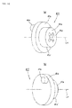
- the hinge device 1 is provided with a base 2 (hinge device base), and a body part 3.
- the base 2 is secured to the side wall 9a.
- the body part 3 removably covers the front of the base 2 (bottom in FIG. 2 and top in FIG. 3 ).
- the body part 3 has a roughly U-shaped profile with an internal space opening toward the back (top in FIG. 2 and bottom in FIG. 3 ), and extends in the front and back directions (second direction orthogonal to the first direction).
- An attachment member 4 is rotatably connected via a connection mechanism 5 to a front end part of the body part 3 (left in FIG. 2 ).
- the door 9b is fixed to this attachment member 4.
- the connection mechanism 5 includes two links 5a, 5b. Base end parts of these links 5a, 5b are respectively connected to the front end part of the body part 3 via respective connection pins 5c, 5d, tip end parts of the links 5a, 5b are respectively connected to the attachment member 4, and in this manner, a four-node link mechanism is configured.
- a four-node link mechanism is configured.
- an end part of an inside surface of the door 9b covers the front end face of the side wall 9a, and the door 9b can be opened and closed.
- a torsion coil spring 5S is provided at the front end part of the body part 3 via a support pin 5e and a support cylinder 5f. Through this torsion coil spring 5S, when in an opened state, the door 9b is biased in the opening direction (clockwise direction in FIG. 2 ), and when in the semi-opened to closed state, the door 9b is biased in the closing direction (counterclockwise direction in FIG. 2 ).
- the hinge device base 2 is configured as follows. As shown in FIG. 5 , the base 2 has a substrate 10, a first movable member 11, and a second movable member 12. As shown in FIG. 6 and FIG. 7(b) , the substrate 10 has a roughly quadrilateral plate shape and has a front side surface 10a facing the front (front direction of the paper in FIG. 6 ), and a rear surface 10b facing the back (front direction of the paper in FIG. 7(b) ). As shown by FIG. 1 and FIG. 2 , this substrate 10 is screwed to the side wall 9a through screw insertion holes 10c at four corners. The front side surface 10a of the substrate 10 configures the "first face" of the claims by being oriented along the first direction and the second direction and being orthogonal to the third direction. The rear surface 10b is fastened to the side wall 9a.
- the first movable member 11 is provided at the front of the substrate 10, and the second movable member 12 is provided at the front of the first movable member 11.
- the first movable member 11 engages with the substrate 10 so as to be capable of moving in the first direction (vertically), incapable of moving in the second direction (front and back direction), and incapable of moving in the third direction (left and right direction).
- the second movable member 12 engages with the first movable member 11 so as to be incapable of moving in the first direction (vertically), capable of moving in the second direction (front and back direction), and capable of moving in the third direction (left and right direction).
- the body part 3 is removably attached to this second movable member 12. In other words, the body part 3 is removably attached indirectly to the first movable member 11.
- a first position adjusting mechanism 30 is interposed between the substrate 10 and the first movable member 11. Through the first position adjusting mechanism 30, the position of the first movable member 11 in the first direction (vertical direction) with respect to the substrate 10 is adjusted.
- a second position adjusting mechanism 40 is interposed between the first movable member 11 and the second movable member 12. Through the second position adjusting mechanism 40, the position of the second movable member 12 in the second direction (front and back direction) with respect to the first movable member 11 is adjusted. Furthermore, a third position adjusting mechanism 50 is interposed between the first movable member 11 and the second movable member 12.
- the position of the second movable member 12 in the third direction (right and left direction) with respect to the first movable member 11 is adjusted. Accordingly, through the base 2 including these three position adjusting mechanisms 30, 40, 50, the position of the body part 3 can be adjusted in three directions, namely the first direction (vertical direction), the second direction (front and back direction), and the third direction (right and left direction). Consequently, the position of the door 9b can be adjusted in three directions with respect to the side wall 9a.
- a shaft guiding recessed section 10d and fitting recessed sections 10e, 10e are formed in the front side surface 10a of the substrate 10.
- the shaft guiding recessed section 10d is arranged at the center part of the front side surface 10a, and has a rectangular or oval shape with the dimension in the first direction (vertical direction) being longer than the dimension in the second direction (front and back direction).
- a pair of fitting recessed sections 10e, 10e is provided in both side directions of the first direction of the shaft guiding recessed section 10d.
- These fitting recessed sections 10e, 10e join the shaft guiding recessed section 10d, extend from the shaft guiding recessed section 10d in a groove shape to both sides in the first direction, and reach both edges in the first direction (vertical direction) of the substrate 10.
- the depth of the fitting recessed section 10e and the depth of the shaft guiding recessed section 10d are mutually the same, and the bottom face of the fitting recessed section 10e and the bottom face of the shaft guiding recessed section 10d are mutually flush.
- the width dimension along the second direction (front and back direction) of the fitting recessed section 10e is smaller than the dimension in the same direction of the shaft guiding recessed section 10d, and the shaft guiding recessed section 10d projects more in the forward direction than the front side edge (left in FIG. 6 ) with respect to the fitting recessed section 10e.
- a step is formed between the front side edge of the shaft guiding recessed section 10d and the front side edge of the fitting recessed section 10e.
- the back side edge (right in FIG. 6 ) with respect to the fitting recessed section 10e joins linearly with the back side edge of the shaft guiding recessed section 10d. Note that the shaft guiding recessed section 10d may also project from the fitting recessed section 10e to the back side (right in FIG. 6 ).
- the first movable member 11 has a surface plate part 11a and a pair of side plate parts 11b, 11b and extends in one direction, and the profile orthogonal to the longitudinal direction thereof is roughly U-shaped.
- This first movable member 11 is arranged on the front side surface 10a of the substrate 10 with the longitudinal direction heading in the second direction (front and back direction) so as to be capable of moving in the first direction (vertical direction).
- a center part in the longitudinal direction of the first movable member 11 covers the shaft guiding recessed section 10d.
- the surface plate part 11a faces the front (right in FIG. 9 ), and the pair of side plate parts 11b, 11b are mutually facing in the first direction (vertical direction).
- An internal space 11c is formed by three plate parts 11a, 11b, 11b. The internal space 11c opens towards the back, or in other words, towards the front side surface 10a of the substrate 10, and is also opened towards both ends of the second direction (front and back direction).
- Fitting sections 11d, 11d are integrally provided at the center of the first movable member 11 in the longitudinal direction.
- the fitting sections 11d, 11d form a pair, and are integrally formed with both sides in the first direction of the first movable member 11, or in other words, with side plate parts 11b, 11b.
- These fitting sections 11d, 11d project outward along the first direction (vertical direction) from respectively corresponding edges of the side plate parts 11b at the side opposite the surface plate part 11 (the substrate 10 side).
- the center part of each fitting section 11d bends in a stepped shape, and a tip end part 11e further at the tip end side than the bent part projects from the bent part to the back (left of FIG.
- the tip end part 11e of the upper fitting section 11d is fitted more into the upper fitting recessed section 10e than the shaft guiding recessed section 10d so as to be capable of sliding in the first direction (vertical direction).
- the tip end part 11e of the lower fitting section 11d is fitted more into the lower fitting recessed section 10e than the shaft guiding recessed section 10d so as to be capable of sliding in the first direction (vertical direction).
- a locking recess 10f is formed at a center part of the front end edge of the substrate 10.
- respective L-shaped locking protrusions 11f are formed at the front end parts (one end part in the second direction) of the pair of side plate parts 11b, 11b of the first movable member 11.
- the locking protrusion 11f catches on the edge of the locking recess 10f (edge in the second direction of the substrate 10) so as to be capable of sliding in the first direction (vertical direction). Through this catching, movement of the first movable member 11 toward the back (right in FIG. 7 ) with respect to the substrate 10 and movement in the third direction (direction orthogonal to the surface of the paper in FIG. 7 ) are hindered.
- connection projection 10g is formed so as to project to the front (front direction of the paper surface in FIG. 6 ) further at the back end side (right side of FIG. 6 ) than the recesses 10d, 10e in the substrate 10.
- the connection projection 10g is formed in a piece type plate shape orthogonal to the first direction.
- a circular connection hole 10h is formed in this connection projection 10g.
- respective circular connection holes 11h are formed at the back end parts (other end in the second direction) of the pair of side plate parts 11b, 11b of the first movable member 11.
- connection pin 14 is inserted, with the shaft line oriented in the first direction (vertical direction), into the connection hole 10h and connection holes 11h, 11h.
- the connection pin 14 pierces the first movable member 11 and the connection projection 10g in the first direction.
- the connection pin 14 is capable of sliding in the first direction (vertical direction) along the shaft line of the connection pin 14 with respect to the connection projection 10g, and through this, movement of the first movable member 11 in the first direction (vertical direction) with respect to the substrate 10 is allowed.
- a head part 14a of the connection pin 14 catches on an outside surface of one of the side plate parts 11b of the first movable member 11. Moreover, a leg part tip end 14c of the connection pin 14 is expanded diametrically by a mechanical fastener and catches on an outer surface of the other side plate part 11b of the first movable member 11. Accordingly, when the first movable member 11 moves in the first direction (vertical direction) with respect to the substrate 10, the connection pin 14 becomes integrated with the first movable member 11 and is moved in the first direction (vertical direction).
- the second movable member 12 is disposed at the side opposite the substrate 10 (in other words, at the front of the first movable member 11) with the first movable member 11 in between.
- the second movable member 12 has a surface plate part 12a and a pair of side plate parts 12b, 12b, it extends in the same direction as the first movable member 11 (front and back direction), and the profile orthogonal to the longitudinal direction thereof is roughly U-shaped.
- the surface plate part 12a is oriented toward the front (right in FIG. 9 ), and the pair of side plate parts 12b, 12b are mutually facing in the first direction (vertical direction).
- An internal space 12c is formed by the three plate parts 12a, 12b, 12b.
- the internal space 12c is opened toward the back, or in other words, toward the substrate 10 side (left in FIG. 9 ), and is also opened toward both ends in the second direction (front and back direction).
- This second movable member 12 covers the first movable member 11, and the first movable member 11 is housed in the internal space 12c.
- the distance between the inside surfaces of the pair of side plate parts 12b, 12b is roughly equivalent to the distance between the outside surfaces of the side plate parts 11b, 11b of the first movable member 11.
- the upper side plate part 12b abuts the outside surface of the upper side plate part 11b
- the lower side plate part 12b abuts the outside surface of the lower side plate part 11b.
- the second movable member 12 moves together with the first movable member 11 in the first direction (vertical direction) with respect to the substrate 10.
- movement of the second movable member 12 with respect to the first movable member 11 is allowed by sliding the side plate part 12b along the side plate part 11b in the second direction (front and back direction) and the third direction (left and right direction).
- Respective elongated hole shaped connection holes 12h are formed in the back end parts of the pair of side plate parts 12b, 12b of the second movable member 12.
- the major axis of the connection hole 12h is oriented in the second direction (front and back direction), and the minor axis is oriented in the first direction (vertical direction).
- the width dimension along the minor axis of the connection hole 12h is larger than the diameter of the connection hole 11h of the first movable member 11, and is roughly equivalent to the diameter of the head part 14a of the connection pin 14.
- This connection pin head part 14a is housed inside the connection hole 12h of one of the side plate parts 12b of the second movable member 12 so as to be capable of sliding along the major axis of the connection hole 12h.
- connection pin 14 the leg part tip end 14c expanded diametrically by a mechanical fastener at the connection pin 14 is housed inside the connection hole 11h of the other side plate part 12b of the second movable member 12 so as to be capable of sliding along the major axis of the connection hole 12h.
- the substrate 10, the first movable member 11, and the second movable member 12 are mutually linked so as to be incapable of separating.
- the second movable member 12 is capable of moving in the second direction (front and back direction) with respect to the substrate 10 and the first movable member 11, between the position at which the back end edge of the connection hole 12h collides with the connection pin 14 and the position at which the front end edge of the connection hole 12h collides with the connection pin 14.
- connection recesses 12d connection parts
- connection parts are formed at the front end parts of the pair of side plate parts 12b, 12b of the second movable member 12.
- a fitting pin 3d of the front end part of the body part 3 is inserted into these connection recesses 12d, 12d.
- respective connection recesses 12e connection parts are formed at the back end parts of the pair of side plate parts 12b, 12b.
- an operating member 6 is rotatably provided at the back end part of the body part 3 via a support pin 3e. This operating member 6 is biased in the counterclockwise direction of FIG.
- the body part 3 is stably mounted to the second movable member 12 and to the hinge device base 2.
- the fitting shaft 6c disconnects from the connection recess 12e, and the body part 3 can be separated from the second movable member 12 and the hinge device base 2.
- the position adjusting mechanism 30 for adjusting the position in the first direction (vertical direction) of the hinge device 1 is configured as described below.
- the first position adjusting mechanism 30 is provided with a first adjusting shaft 31, and a pair of substrate side guiding sections 32, 32.
- the first adjusting shaft 31 is provided integrally with a first shaft part 31a and a first shaft-side guiding section 31 c.
- the first shaft part 31a includes a cylindrical part 31a', a disk part 31b, and a projecting shaft part 31d.
- the disk part 31b which has a larger diameter than the cylindrical part 31a', is integrally provided at the back of the cylindrical part 31a' (left in FIG.
- the diameter of the cylindrical part 31a' is roughly equivalent to the distance between the inside surfaces of the pair of side plate parts 11b, 11b of the first movable member 11.
- the diameter of the disk part 31b is roughly equivalent to the width dimension along the second direction (front and back direction) of the shaft guiding recessed section 10d.
- the first shaft-side guiding section 31 c is integrally provided at the back surface (left side surface in FIG. 10(b) ) of the disk part 31b.
- the first shaft-side guiding section 31c projects from the disk part 31b, and is spiral shaped.
- a cross-shaped groove 31e is formed in the top surface facing the front (right side) of the projecting shaft part 31d.
- this first adjusting shaft 31 is interposed between the first movable member 11 and the substrate 10 with the center shaft line L31 oriented in the third direction (left and right direction).
- the cylindrical part 31a' of the first adjusting shaft 31 is housed in the internal space 11c of the first movable member 11.
- a pair of side plates 11b, 11b of the first movable member 11 roughly abuts the cylindrical part 31a' from both sides in the first direction (vertical direction).
- the disk part 31b and the first shaft-side guiding section 31 c are housed in the shaft guiding recessed section 10d.
- the first adjusting shaft 31 is capable of moving in the first direction (vertical direction) such that it is capable of being guided along the front side edge and the back side edge of the shaft guiding recessed section 10d with respect to the substrate 10, and is not capable of moving in the second direction (front and back direction).
- a shaft support hole 11k is formed at a center part in the longitudinal direction (second direction) of the surface plate part 11a of the first movable member 11.
- the projecting shaft part 31d is rotatably inserted into this shaft support hole 11k.
- a step between the circumferential side surface of the projecting shaft part 31 d and the cylindrical part 31 a' catches on a circumferential edge of the shaft support hole 11k of the surface plate part 11a.
- each substrate side guiding section 32 includes a guiding portion 32a and a leg part 32b.
- the guiding portion 32a is formed in a small cylindrical shape, and a flange part 32c is provided at the back end part thereof so as to project radially outward.
- the leg part 32b projects from the back surface of the guiding portion 32a.
- the guiding portions 32a, 32a of the pair of substrate side guiding sections 32, 32 are disposed in the shaft guiding recessed section 10d so as to be slightly separated and mutually facing in the first direction (vertical direction).
- an oval shaped mounting recess 10j long in the first direction (vertical direction) is formed in the bottom face of the shaft guiding recessed section 10d of the substrate 10.
- a pair of small circular mounting holes 10k, 10k is formed in the bottom face of this mounting recess 10j.
- These mounting holes 10k, 10k are disposed so as to be mutually separated slightly in the first direction (vertical direction), and respectively penetrate the substrate 10 in the thickness direction (third direction).
- the flange part 32c of the two substrate side guiding sections 32 is accommodated in the mounting recess 10j, and the leg part 32b is inserted into the respectively corresponding mounting hole 10k.
- This leg part 32b is fixed to the substrate 10 by a mechanical fastener or the like.
- first shaft-side guiding section 31c of the first adjusting shaft 31 is inserted between the guiding portions 32a, 32a of the pair of substrate side guiding sections 32, 32. In this manner, the first shaft-side guiding section 31 c and the substrate side guiding sections 32, 32 are engaged.
- An engaging part 31c' of the first shaft-side guiding section 31c with the substrate side guiding sections 32, 32 is eccentric with respect to the first rotation axis line L31.
- the first shaft-side guiding section 31 c and the substrate side guiding sections 32, 32 mutually engage and guide, and thereby rotation of the first adjusting shaft 31 is converted to parallel movement of the first adjusting shaft 31 along the first face 10a.
- a window hole 12k is formed in the surface plate part 12a of the second movable member 12.
- the window hole 12k is formed as an elongated hole extending in the second direction (front and back direction).
- a window hole 3k is formed in the body part 3.
- the window hole 3k is formed as an elongated hole extending in the second direction (front and back direction).
- the window hole 3k and the window hole 12k overlap the shaft support hole 11k in the third direction (left and right direction). In this manner, the projecting shaft part 31d is exposed at the front (front direction of the paper surface in FIG. 1 ) through the window holes 3k, 12k.
- the first adjusting shaft 31 can be rotated around the first rotation axis line L31 by inserting a screw rotation tool such as a Phillips-head screwdriver through the window holes 3k, 12k and into the cross-shaped groove 31 e, and then rotating the tool.
- a screw rotation tool such as a Phillips-head screwdriver
- the engaging part 31c' is displaced in the circumferential direction of the spiral-shaped first shaft-side guiding section 31 c, and as a result, the distance between the engaging part 31 c' and the first rotation axis line L31 changes.
- the first rotation axis line L31 displaces with respect to the substrate side guiding section 32.
- the first adjusting shaft 31 moves in the first direction (vertical direction) with respect to the substrate 10 by the abovementioned transformation action in the movement direction between the first shaft-side guiding section 31c and the substrate side guiding section 32.
- the first movable member 11, second movable member 12, and body part 3 also move in the first direction (vertical direction).
- the pair of fitting sections 11d, 11d are guided in the first direction (vertical direction) along the respective fitting recessed sections 10e.
- the position of the door 9b can be adjusted in the first direction (vertical direction) with respect to the side wall 9a.
- a hexagonal wrench or other screw rotation tool can be used to rotate the first adjusting shaft 31.
- the position adjusting mechanism 40 for adjusting the position in the second direction (front and back direction) with respect to the hinge device 1 is configured as described below.
- the second position adjusting mechanism 40 is provided with a second adjusting shaft 41, and a pair of first movable side guiding sections 42, 42.
- the second adjusting shaft 41 is provided integrally with a second shaft part 41 a and a second shaft-side guiding section 41c.
- the second shaft part 41a includes a cylindrical part 41a' and a disk part 41b.
- the cylindrical part 41a' and the disk part 41b are mutually arranged on the same center shaft line (second rotation axis line L41).
- the shaft length of the cylindrical part 41 a' is shorter than the shaft length of the cylindrical part 31a' of the first adjusting shaft 31.
- a cross-shaped groove 41e is formed in the front side surface of the cylindrical part 41a'.
- the disk part 41b which has a larger diameter than the cylindrical part 41a', is integrally provided at the back of the cylindrical part 41a' (left of FIG. 11 (a) ).
- the diameter of the disk part 41b is larger than the diameter of the disk part 31b of the first adjusting shaft 31, and is roughly equivalent to the distance between the inside surfaces of the pair of side plate parts 12b, 12b of the second movable member 12. As shown in FIG.
- a second shaft-side guiding section 41 c is integrally provided at the back surface of this disk part 41b (left side surface in FIG. 11(a) ).
- the second shaft-side guiding section 41c projects from the disk part 41b and is spiral shaped.
- this second adjusting shaft 41 is interposed between the first and second movable members 11, 12 with the center shaft line thereof (second rotation axis line L41) oriented so as to be parallel (third direction) with the first rotation axis line L31.
- second position adjusting mechanism 40 when viewed from the front (front direction of the paper surface in FIG. 7(a) ), the second position adjusting mechanism 40 is arranged deviated to the back end side in the second direction (right side in FIG. 7(a) ) with respect to the first position adjusting mechanism 30.
- the disk part 41b and the second shaft-side guiding section 41c of the second adjusting shaft 41 are housed in the internal space 12c of the second movable member 12 so as to be sandwiched between the surface plate part 12a of the second movable member 12 and the surface plate part 11a of the first movable member 11. Furthermore, the pair of side plate parts 12b, 12b of the second movable member 12 roughly abuts the disk part 41b from both sides in the second direction.
- a shaft support hole 12m is formed in the back end part of the surface plate part 12a of the second movable member 12.
- the cylindrical part 41a' is inserted into this shaft support hole 12m.
- a step between the circumferential side surface of the cylindrical part 41a' and the disk part 41b catches on the circumferential edge of the shaft support hole 12m at the surface plate part 12a.
- the second shaft part 41a and the second adjusting shaft 41 engage such that they are able to rotate around the second rotation axis line L41 with respect to the second movable member 12, and are unable to move in the first direction (vertical direction) and the second direction (front and back direction).
- the second adjusting shaft 41 is able to move in the second direction (front and back direction) with respect to the first movable member 11 together with the second movable member 12. Accordingly, with respect to the first movable member 11, the second rotation axis line L41 is able to move only in the second direction (front and back direction) with the exception of the third direction.
- each first movable side guiding section 42 includes a guiding portion 42a and a leg part 42b.
- the guiding portion 42a is formed in a small cylindrical shape, and a flange part 42c is provided at the back end part thereof so as to project radially outward.
- the leg part 42b projects from the back surface of the guiding portion 42a.
- the guiding portions 42a, 42a of the pair of first movable side guiding sections 42, 42 are disposed slightly separated and mutually facing in the second direction (front and back direction), and respectively project to the front of the first movable member 11.
- an oval shaped mounting recess 11m is formed in the front side surface of the surface plate part 11 a of the first movable member 11 so as to extend from the shaft support hole 11k to the back end side.
- a pair of small circular mounting holes 11n, 11n is formed in the bottom face of this mounting recess 11m. These mounting holes 11n, 11n are disposed so as to be mutually separated slightly in the second direction (front and back direction), and respectively penetrate the surface plate part 11 a in the thickness direction.
- the flange part 42c of the two first movable side guiding sections 42 is accommodated in the mounting recess 11m, and the leg part 42b is inserted into the respectively corresponding mounting hole 11n.
- This leg part 42b is fixed to the first movable member 11 by a mechanical fastener or the like.
- the second shaft-side guiding section 41c of the second adjusting shaft 41 is inserted between the guiding portions 42a, 42a of the pair of first movable side guiding sections 42, 42. In this manner, the second shaft-side guiding section 41c and the first movable side guiding section 42, 42 are engaged.
- An engaging part 41c' with the first movable side guiding sections 42,42 with respect to the second shaft-side guiding section 41c is eccentric with respect to the second rotation axis line L41.
- the second shaft-side guiding section 41c and the first movable side guiding sections 42, 42 mutually engage and guide, and thereby rotation of the second adjusting shaft 41 is converted to a parallel direction movement along the surface plate part 11 a of the second adjusting shaft 41.
- a window hole 3m is formed further to the back end side than the window hole 3k in the body part 3.
- the window hole 3m overlaps the shaft support hole 12m in the third direction (left and right direction).
- the second shaft part 41a is exposed through the window hole 3m.
- the second adjusting shaft 41 can be rotated around the second rotation axis line L41 by inserting a screw rotation tool such as a Phillips-head screwdriver through the window hole 3m and into a cross-shaped groove 41 e, and then rotating the tool.
- the engaging part 41 c' is displaced in the circumferential direction of the spiral-shaped second shaft-side guiding section 41c, and as a result, the distance between the engaging part 41c' and the second rotation axis line L41 changes.
- the second rotation axis line L41 displaces with respect to the first movable side guiding section 42.
- the second adjusting shaft 41 moves in the second direction (front and back direction) with respect to the first movable member 11 by the abovementioned transformation action in the movement direction between the second shaft-side guiding section 41 c and the first movable side guiding section 42.
- the second movable member 12 and body part 3 also move in the second direction (front and back direction) with respect to the first movable member 11.
- the position of the door 9b can be adjusted in the second direction (front and back direction) with respect to the side wall 9a.
- a hexagonal wrench or other screw rotation tool can be used to rotate the second adjusting shaft 41.
- the position adjusting mechanism 50 for adjusting the position in the third direction (left and right direction) with respect to the hinge device 1 is configured as described below.
- the third position adjusting mechanism 50 is provided with a third adjusting screw 51.
- the third adjusting screw 51 is interposed between the first movable member 11 and the second movable member 12.
- the third position adjusting mechanism 50 is disposed shifted to the front end side (left in FIG. 7(a) ) of the second direction with respect to the first position adjusting mechanism 30.
- an opened slit 11q is formed in the front end part of the surface plate part 11 a of the first movable member 11.
- the opened slit 11q reaches the front edge of the surface plate part 11a and is opened.
- a screw hole 12q is formed in the front end part of the surface plate part 12a of the second movable member 12.
- the third adjusting screw 51 is locked such that it is capable of rotating in the opened slit 11q of the first movable member 11, incapable of moving in the first direction (vertical direction), capable of moving in the second direction (front and back direction), and incapable of moving in the third direction (left and right direction), and is screwed into the screw hole 12q of the second movable member 12. As shown in FIG. land FIG.
- a window hole 3q is formed further to the front end side than the window hole 3k in the body part 3.
- the window hole 3q overlaps the screw hole 12q in the third direction (left and right direction).
- the head part of the third adjusting screw 51 is exposed through the window hole 3q.
- the shaft guiding recessed section 10d of the substrate 10 and a pair of fitting recessed sections 10e, 10e are both formed on the front side surface 10a, and are mutually joined and integrated, and therefore, the substrate 10 can be easily machined.
- a mold portion corresponding to the shaft guiding recessed section 10d and a mold portion corresponding to each fitting recessed section 10e can be configured with a single convex part, and a press mold can be easily fabricated.
- the shaft guiding recessed section 10d and the pair of fitting recessed sections 10e, 10e can be integrally formed, and forming can be easily performed with one to a few cutting steps Moreover, because the bottom parts of the shaft guiding recessed section 10d and the fitting recessed section 10e are flush, machining can be further simplified. In other words, if the substrate 10 is manufactured by press machining, a mold portion corresponding to the shaft guiding recessed section 10d and a mold portion corresponding to the fitting recessed section 10e can be configured with a single convex part having an overall uniform height, and a press mold can be more easily fabricated. Moreover, even if the substrate 10 is manufactured through cutting machining, the shaft guiding recessed section 10d and the fitting recessed section 10e can be integrally formed with the same cutting depth.
- the first adjusting shaft 31, the first movable member 11 to which the first movable side guiding section 42 has been installed, the second adjusting shaft 41, and the second movable member 12 are placed in order on the front of the substrate 10 such that they are stacked in the third direction, and next, the first and second movable members 11, 12 are connected by the third adjusting screw 51, and the substrate 10 and the movable members 11, 12 are connected by the connection pin 14, and thereby the base 2 can be easily assembled.
- the second adjusting shaft 41 is sandwiched between the abovementioned first movable member 11 and second movable member 12 in advance, and is connected by the third adjusting screw 51, after which the unit is installed on the front side surface 10a of the substrate 10, and then the substrate 10 and movable members 11, 12 can be connected by the connection pin 14. Furthermore, the first position adjusting mechanism 30 is interposed between the substrate 10 and the first movable member 11, and the second position adjusting mechanism 40 is interposed between the first movable member 11 and the second movable member 12, and therefore the assembly of the hinge device base 2 can be further simplified.
- the locking protrusion 11f catches on the locking recess 10f of the substrate 10
- the first moveable member 11 is made to cover from the front the first adjusting shaft 31 disposed in advance on the shaft guiding recessed section 10d
- the pair of fitting sections 11d, 11d may be accommodated in the fitting recessed sections 10e, 10e from the front, and therefore there is no need to slide the first movable member 11 in the first direction with respect to the substrate 10. Accordingly, even if the first adjusting shaft 31 is installed in advance on the shaft guiding recessed section 10d, this first adjusting shaft 31 does not hinder the operation of attaching the first movable member 11 to the substrate 10.
- the pair of fitting sections 11d, 11d fits to the respectively corresponding fitting recessed section 10e such that sliding in the first direction (vertical direction) is possible, and therefore the first movable member 11 can be stably moved parallel to the first direction (vertical direction). Accordingly, the positions of the body part 3 and the door 9b can be stably adjusted in the first direction (vertical direction).
- the first position adjusting mechanism 30 is interposed between the substrate 10 and the first movable member 11, and the second position adjusting mechanism 40 is interposed between the first movable member 11 and the second movable member 12, and therefore position adjustment in the first direction and position adjustment in the second direction can be performed in a mutually independent manner.
- the first to the third position adjusting mechanisms 30, 40, 50 are constructed only at the hinge device base 2 and do not straddle the hinge device base 2 and the body part 3, and therefore position adjustments of the body part 3 and the door 9b in three directions, namely the first to the third directions, can be performed with only the hinge device base 2.
- FIG. 12 to FIG. 14 show a second embodiment of the present invention.
- the second embodiment pertains to a modified example of the first position adjusting mechanism 30 and the second position adjusting mechanism 40.
- a recess-shaped substrate side guiding section 10p is provided in the shaft guiding recessed section 10d of the substrate 10 in the second embodiment.
- the substrate side guiding section 10p extends linearly in the second direction (front and back direction), and forms a slit piercing the substrate 10 in the thickness direction (third direction).
- a small, cylindrical first shaft-side guiding section 31p is formed in the disk part 31b of a first adjusting shaft 31X.
- the first shaft-side guiding section 31p is eccentric with respect to the shaft line (first rotation axis line L31) of the first adjusting shaft 31X.
- the disk part 31b is accommodated in the shaft guiding recessed section 10d, and the first shaft-side guiding section 31p is inserted into the substrate side guiding section 10p.
- the first adjusting shaft 31X is capable of moving in the first direction (vertical direction) along the shaft guiding recessed section 10d with respect to the substrate 10 and is incapable of moving in the second direction (front and back direction).
- the first shaft-side guiding section 31p is incapable of moving in the first direction (vertical direction) with respect to the substrate 10, and is capable of moving in the second direction (front and back direction).
- the projecting shaft part 31d of the first adjusting shaft 31X is rotatably inserted into the shaft support hole 11k of the first movable member 11.
- a first movable side guiding section 11p is provided at the surface plate part 11 a of the first movable member 11 of the second embodiment.
- the first movable side guiding section 11p forms a slit shape extending in the first direction (vertical direction).
- a small, cylindrical second shaft-side guiding section 41p is formed at the disk part 41b of a second adjusting shaft 41X.
- the second shaft-side guiding section 41p is eccentric with respect to the shaft line (second rotation axis line L41) of the second adjusting shaft 41X.
- the second shaft part 41a of this second adjusting shaft 41X is rotatably inserted into the shaft support hole 12m of the second movable member 12. Moreover, the disk part 41b is interposed between the surface plate parts 11a, 12a and the between the pair of side plate parts 12b, 12b, and is accommodated in the internal space 12c of the second movable member 12. Accordingly, the second adjusting shaft 41X is capable of moving around the second rotation axis line L41 with respect to the first movable member 11, is not capable of moving in the first direction (vertical direction), and is capable of moving in the second direction (front and back direction).
- the second shaft-side guiding section 41p is inserted into the first movable side guiding section 11p, and is thereby capable of moving in the first direction (vertical direction) with respect to the first movable member 11, and is incapable of moving in the second direction (front and back direction).
- a transformation action in the movement direction between the second shaft-side guiding section 41p and the first movable side guiding section 11p is manifest by rotating the second adjusting shaft 41X around the second rotation axis line L41, and the position of the second movable member 12 can be adjusted in the second direction (front and back direction) with respect to the first movable member 11.
- the present invention is not limited by the above-described embodiments, and various modifications can be adopted within a scope that does not depart from the gist thereof.
- the second movable member 12 may be omitted, and the body part 3 may be removably attached directly to the first movable member 11.
- the second position adjusting mechanism 40 or the third position adjusting mechanism 50 may be omitted.
- the second position adjusting mechanism 40 or the third position adjusting mechanism 50 may be provided at the first movable member 11 between the movable member 11 and the body part 3.
- the depth of the shaft guiding recessed section 10d and the depth of the fitting recessed section 10e may be mutually different, and a step may be formed between these recesses 10d, 10e.
- the width dimensions along the second direction (front and back direction) of the shaft guiding recessed section 10d and the fitting recessed section 10e may be mutually equivalent.
- a groove having a uniform width overall may be formed in the front side surface 10a (first face) of the substrate 10 so as to extend in the first direction, a portion of the groove thereof (for example, the center part) may configure the shaft guiding recessed section 10d, and another portion of the groove thereof (for example, both sides) may configure the fitting recessed section 10e.
- the diameter of the disk part 31b of the first adjusting shaft 31 may not only be roughly equivalent to the width dimension along the second direction (front and back direction) of the shaft guiding recessed section 10d, but also roughly equivalent to the width dimension along the second direction (front and back direction) of the fitting recessed section 10e.
- the shaft guiding recessed section 10d and the fitting recessed section 10e do not necessarily have to be joined, and may be mutually separated. At least one fitting recessed section 10e need only be formed on the front side surface 10a (first face) of the substrate 10.
- At least one fitting section 11d need only be provided at the first movable member 11,
- the fitting section 11d need only fit to the fitting recessed section 10e such that it is capable of sliding in the first direction, and does not necessarily have to project in the first direction from the side plate part 11b of the first movable member 11, and for example, the fitting section 11d may project straight to the back in the third direction from the side plate parts 11b.
- the substrate side guiding section 32 may be integrally formed with the substrate 10.
- the first movable side guiding section 42 may be integrally formed with the first movable member 11.
- the specific aspect of the present invention is not limited to the above-described first and second embodiments.
- a spiral-shaped projection may be provided at the shaft guiding recessed section 10d, and as the first shaft-side guiding section engaging therewith, a small, cylindrical projection may be eccentrically provided at the back surface of the first adjusting shaft 31.
- the specific aspect of the present invention is not limited to the above-described first and second embodiments.
- a spiral-shaped projection may be provided at the first movable member 11, and as the second shaft-side guiding section engaging therewith, a small, cylindrical projection may be eccentrically provided at the back surface of the second adjusting shaft 41.
- the present invention can be applied to hinges for rotatably connecting a door to a side wall of furniture or the like, for example.
Landscapes
- Engineering & Computer Science (AREA)
- Mechanical Engineering (AREA)
- Hinges (AREA)
Abstract
Description
- The present invention pertains to a hinge device for rotatably attaching a door to a frame of furniture or the like for example, and to a base for the hinge device, and more specifically pertains to a hinge device having an adjustment mechanism for adjusting a position of a door with respect to a frame and to a base thereof.
- Ordinarily, this type of hinge device has a base (hinge device base), a body part removably connected to this base, and an attachment member rotatably connected to a tip end part of the body part (for example, see patent document 1). The base is attached to a frame, and the attachment member is attached to a door. In this manner, the door is rotatably supported to the frame via the hinge device.
- Furthermore, the hinge device of patent document 1 is provided with a position adjusting mechanism for adjusting the position of the door with respect to the frame in three directions by adjusting the position of the body part with respect to the base in three directions, namely the front and back direction, the right and left direction, and the vertical direction. More specifically, the base described by patent document 1 includes a base plate and a middle member, and the body part is connected to the middle member so as to be capable of movement in two directions, namely the front and back direction and the left and right direction. A mechanism for adjusting the position in the front and back direction and configured from a spiral cam and rack, and a mechanism for adjusting the position left and right and configured from a screw are provided between the middle member and the body part. Moreover, the base plate is configured from two plate members. These two plate members are connected so as to be capable of moving up and down (height direction), and a mechanism for adjusting the position vertically and configured from a spiral cam and rack separate from the abovementioned spiral cam and rack is provided between the two plate members themselves.
- A recess is formed in the front side surface of one of the plate members, and the rack of the abovementioned vertical position adjusting mechanism is formed at the bottom face of this recess. The spiral cam of the vertical position adjusting mechanism is arranged in this recess, and engages with the rack, and a portion of the spiral cam protrudes more than an edge of one side of the abovementioned one plate member. A cylindrical retaining body is provided at the front side surface of the spiral cam so as to project, and a cross-shaped groove in which a Phillips-head screwdriver can be inserted is formed in the front side surface of the cylindrical retaining body. Moreover, a circular opening in which the cylindrical retaining body is rotatably inserted is formed in the other plate member. Furthermore, projection bodies having an L-shape profile are integrally formed respectively in both edges of the other plate member, and these projection bodies slidably catch on both edges of the one plate member. Accordingly, the two plate members fit together by mutually sliding, but at this time, the other plate member catches on the protrusion portion of the spiral cam and cylindrical retaining body. Therefore, the hinge device of patent document 1 is not easy to machine and manufacture.
- Patent Document 1: Japanese Patent No.
3198417 FIG. 6 andFIG. 7 ) - In light of the abovementioned circumstances, an object of the present invention is to simplify the machining and manufacturing of the hinge device.
- In order to resolve the abovementioned problem, the present invention pertains to a hinge device including a base, a body part, and an attachment member rotatably connected to the body part, wherein the base includes a substrate having a first face, a first movable member provided on the first face so as to be movable in a first direction along the first face with respect to the substrate, and a first position adjusting mechanism for adjusting a position of the first movable member in the first direction with respect to the substrate, and the first movable member and the body part are removably connected either indirectly or directly. The present invention also pertains to a hinge device base including a substrate having a first face, a first movable member provided on the first face so as to be capable of moving in a first direction along the first face with respect to the substrate, and a first position adjusting mechanism for adjusting a position of the first movable member in the first direction with respect to the substrate, and the first movable member is removably connected either indirectly or directly to a body part, which is rotatably connected to an attachment member.
With the abovementioned hinge device or hinge device base of the present invention, a shaft guiding recessed section and a fitting recessed section are formed on the first face of the substrate; as the first position adjusting mechanism, a substrate side guiding section is provided on the shaft guiding recessed section, and a first adjusting shaft is provided between the substrate and the first movable member, and the first adjusting shaft has, in an integrated form, a first shaft part which rotatably engages to the first movable member around a first rotation axis line orthogonal to the first face and is inserted into the shaft guiding recessed section so as to be guided in the first direction, and a first shaft-side guiding section which engages with the substrate side guiding section; and a fitting section is provided in the first movable member, and the fitting section is inserted into the fitting recessed section so as to be capable of sliding in the first direction.
In this manner, machining and manufacturing of the substrate can be simplified, and manufacturing of the hinge device can be simplified. - The shaft guiding recessed section and the fitting recessed section are preferably joined such that the mutual bottom faces thereof become flush. Through this, machining and manufacturing of the substrate can be further simplified, and manufacturing of the hinge device can be further simplified.
- Preferably, the fitting recessed section is provided as a pair at both sides of the shaft guiding recessed section in the first direction, the fitting section is provided as a pair at both sides of the first movable member in the first direction, and each fitting section is inserted into the corresponding fitting recessed section so as to be capable of sliding in the first direction. In this manner, the first movable member can be more stably installed on the substrate, and the first movable member can be more stably guided in the first direction.
- Preferably, the first movable member runs along the first face and extends in a second direction orthogonal to the first direction, and a locking protrusion is formed at one end of the first movable member in the second direction, and the locking protrusion catches on an edge of the substrate in the second direction so as to be capable of sliding in the first direction; and a connection projection is further provided at the substrate, and the other end of the first movable member in the second direction is connected by a connection pin, extending in the first direction, to the connection projection so as to be capable of moving in the first direction.
Through this, assembly of the hinge device base can be simplified. - Preferably, the base further includes a second movable member running along the first face with respect to the first movable member and capable of moving in a second direction orthogonal to the first direction, and a second position adjusting mechanism for adjusting a position of the second movable member in the second direction with respect to the first movable member, and the second movable member has a connection part removably connecting to the body part, sandwiches the first movable member, and is provided at a side opposite the substrate; and as the second position adjusting mechanism, a first movable side guiding section is provided at the first movable member, and a second adjusting shaft is provided between the first movable member and the second movable member, and the second adjusting shaft has, in an integrated form, a second shaft part rotatably engaged to the second movable member around a second rotation axis line parallel to the first rotation axis line, and a second shaft-side guiding section which engages with the first movable side guiding section.
In this manner, the position of the body part can be adjusted in the second direction as well. In addition, assembly of the hinge device base can also be simplified. - According to the present invention, machining and manufacturing or a hinge device base can be simplified.
-
-
FIG. 1 is an elevation view as viewed from the front with a hinge device according to a first embodiment of the present invention attached to a frame, and a door of the frame opened. -
FIG. 2 is a cross-sectional plan view of the hinge device along the line II-II ofFIG. 1 . -
FIG. 3 is a perspective view showing the body party of the hinge device and the hinge device base separated. -
FIG. 4 is an exploded perspective view of the body part. -
FIG. 5 is an exploded perspective view of the hinge device base. -
FIG. 6 is an elevation view showing a substrate of the hinge device base viewed from the front. -
FIG. 7(a) is an elevation view showing the hinge device base viewed from the front, andFIG. 7(b) is a rear view of the hinge device base as seen from the back side. -
FIG. 8 is a cross-sectional plan view of the hinge device base along the line VIII-VIII ofFIG. 7(a) . -
FIG. 9 is a vertical cross-sectional view of the hinge device base along the line IX-IX ofFIG. 7(a) . -
FIG. 10(a) is a perspective view of a first adjusting shaft of the hinge device base as viewed from the front and forward direction.FIG. 10(b) is a perspective view of the first adjusting shaft as viewed from the back and forward direction. -
FIG. 11(a) is a perspective view of a second adjusting shaft of the hinge device base as viewed from the front and forward direction.FIG. 11(b) is a perspective view of the second adjusting shaft as viewed from the back and forward direction. -
FIG. 12 is an exploded perspective view of a base of a hinge device according to a second embodiment of the present invention. -
FIG. 13 shows a first adjusting shaft of the hinge device base according to the second embodiment,FIG. 13(a) is a perspective view as viewed from the front and forward direction, andFIG. 13(b) is a perspective view as viewed from the back and forward direction. -
FIG. 14 shows a second adjusting shaft of the hinge device base according to the second embodiment,FIG. 14(a) is a perspective view as viewed from the front and forward direction, andFIG. 14(b) is a perspective view as viewed from the back and forward direction. - Embodiments of the present invention are described below.
FIGS. 1 to 11 show a first embodiment of the present invention.
As shown byFIG. 1 andFIG. 2 , adoor 9b is rotatably connected around a vertical axis via a hinge device 1 to avertical side wall 9a (frame body) of a frame 9 of furniture or the like, for example. The hinge device 1 straddles from theside wall 9a to thedoor 9b with a front part oriented toward the right direction, a back part oriented toward the left direction, a tip end part oriented toward the front direction, a back end part oriented toward the interior direction, and the width direction oriented in the vertical direction (first direction). Furthermore, the hinge device 1 is provided with a function to adjust the position of thedoor 9b with respect to theside wall 9a in three directions, namely, the vertical, front and back (second direction orthogonal to the first direction), and left and right direction (third direction orthogonal to both the first direction and the second direction). - More specifically, as shown in
FIG. 2 andFIG. 3 , the hinge device 1 is provided with a base 2 (hinge device base), and abody part 3. Thebase 2 is secured to theside wall 9a. Thebody part 3 removably covers the front of the base 2 (bottom inFIG. 2 and top inFIG. 3 ). Thebody part 3 has a roughly U-shaped profile with an internal space opening toward the back (top inFIG. 2 and bottom inFIG. 3 ), and extends in the front and back directions (second direction orthogonal to the first direction). An attachment member 4 is rotatably connected via aconnection mechanism 5 to a front end part of the body part 3 (left inFIG. 2 ). Thedoor 9b is fixed to this attachment member 4. As shown inFIG. 2 andFIG. 4 , theconnection mechanism 5 includes twolinks links body part 3 via respective connection pins 5c, 5d, tip end parts of thelinks FIG. 2 ), a front end face of theside wall 9a and an end face of thedoor 9b face each other, and in the closed state (long and short dashed line ofFIG. 2 ), an end part of an inside surface of thedoor 9b covers the front end face of theside wall 9a, and thedoor 9b can be opened and closed. Furthermore, atorsion coil spring 5S is provided at the front end part of thebody part 3 via asupport pin 5e and asupport cylinder 5f. Through thistorsion coil spring 5S, when in an opened state, thedoor 9b is biased in the opening direction (clockwise direction inFIG. 2 ), and when in the semi-opened to closed state, thedoor 9b is biased in the closing direction (counterclockwise direction inFIG. 2 ). - The
hinge device base 2 is configured as follows.
As shown inFIG. 5 , thebase 2 has asubstrate 10, a firstmovable member 11, and a secondmovable member 12. As shown inFIG. 6 andFIG. 7(b) , thesubstrate 10 has a roughly quadrilateral plate shape and has afront side surface 10a facing the front (front direction of the paper inFIG. 6 ), and arear surface 10b facing the back (front direction of the paper inFIG. 7(b) ). As shown byFIG. 1 andFIG. 2 , thissubstrate 10 is screwed to theside wall 9a throughscrew insertion holes 10c at four corners. Thefront side surface 10a of thesubstrate 10 configures the "first face" of the claims by being oriented along the first direction and the second direction and being orthogonal to the third direction. Therear surface 10b is fastened to theside wall 9a. - As shown in
FIG. 8 andFIG. 9 , the firstmovable member 11 is provided at the front of thesubstrate 10, and the secondmovable member 12 is provided at the front of the firstmovable member 11. The firstmovable member 11 engages with thesubstrate 10 so as to be capable of moving in the first direction (vertically), incapable of moving in the second direction (front and back direction), and incapable of moving in the third direction (left and right direction). The secondmovable member 12 engages with the firstmovable member 11 so as to be incapable of moving in the first direction (vertically), capable of moving in the second direction (front and back direction), and capable of moving in the third direction (left and right direction). Thebody part 3 is removably attached to this secondmovable member 12. In other words, thebody part 3 is removably attached indirectly to the firstmovable member 11. - As shown in
FIG. 2 andFIG. 5 , a firstposition adjusting mechanism 30 is interposed between thesubstrate 10 and the firstmovable member 11. Through the firstposition adjusting mechanism 30, the position of the firstmovable member 11 in the first direction (vertical direction) with respect to thesubstrate 10 is adjusted. A secondposition adjusting mechanism 40 is interposed between the firstmovable member 11 and the secondmovable member 12. Through the secondposition adjusting mechanism 40, the position of the secondmovable member 12 in the second direction (front and back direction) with respect to the firstmovable member 11 is adjusted. Furthermore, a thirdposition adjusting mechanism 50 is interposed between the firstmovable member 11 and the secondmovable member 12. Through the thirdposition adjusting mechanism 50, the position of the secondmovable member 12 in the third direction (right and left direction) with respect to the firstmovable member 11 is adjusted. Accordingly, through thebase 2 including these threeposition adjusting mechanisms body part 3 can be adjusted in three directions, namely the first direction (vertical direction), the second direction (front and back direction), and the third direction (right and left direction). Consequently, the position of thedoor 9b can be adjusted in three directions with respect to theside wall 9a. - The structure of the
hinge device base 2 is described below in greater detail.
As shown inFIG. 6 , a shaft guiding recessedsection 10d and fitting recessedsections front side surface 10a of thesubstrate 10. The shaft guiding recessedsection 10d is arranged at the center part of thefront side surface 10a, and has a rectangular or oval shape with the dimension in the first direction (vertical direction) being longer than the dimension in the second direction (front and back direction). - A pair of fitting recessed
sections section 10d. These fitting recessedsections section 10d, extend from the shaft guiding recessedsection 10d in a groove shape to both sides in the first direction, and reach both edges in the first direction (vertical direction) of thesubstrate 10. The depth of the fitting recessedsection 10e and the depth of the shaft guiding recessedsection 10d are mutually the same, and the bottom face of the fitting recessedsection 10e and the bottom face of the shaft guiding recessedsection 10d are mutually flush. The width dimension along the second direction (front and back direction) of the fitting recessedsection 10e is smaller than the dimension in the same direction of the shaft guiding recessedsection 10d, and the shaft guiding recessedsection 10d projects more in the forward direction than the front side edge (left inFIG. 6 ) with respect to the fitting recessedsection 10e. A step is formed between the front side edge of the shaft guiding recessedsection 10d and the front side edge of the fitting recessedsection 10e. The back side edge (right inFIG. 6 ) with respect to the fitting recessedsection 10e joins linearly with the back side edge of the shaft guiding recessedsection 10d.
Note that the shaft guiding recessedsection 10d may also project from the fitting recessedsection 10e to the back side (right inFIG. 6 ). - As shown in
FIG. 5 andFIG. 9 , the firstmovable member 11 has asurface plate part 11a and a pair ofside plate parts movable member 11 is arranged on thefront side surface 10a of thesubstrate 10 with the longitudinal direction heading in the second direction (front and back direction) so as to be capable of moving in the first direction (vertical direction). A center part in the longitudinal direction of the firstmovable member 11 covers the shaft guiding recessedsection 10d. Thesurface plate part 11a faces the front (right inFIG. 9 ), and the pair ofside plate parts internal space 11c is formed by threeplate parts internal space 11c opens towards the back, or in other words, towards thefront side surface 10a of thesubstrate 10, and is also opened towards both ends of the second direction (front and back direction). - Fitting
sections movable member 11 in the longitudinal direction. Thefitting sections movable member 11, or in other words, withside plate parts fitting sections side plate parts 11b at the side opposite the surface plate part 11 (thesubstrate 10 side). The center part of eachfitting section 11d bends in a stepped shape, and atip end part 11e further at the tip end side than the bent part projects from the bent part to the back (left ofFIG. 9 ) with respect to the portion of the base end side (side plate part 11b side). As shown inFIG. 7(a) andFIG. 9 , thetip end part 11e of the upperfitting section 11d is fitted more into the upper fitting recessedsection 10e than the shaft guiding recessedsection 10d so as to be capable of sliding in the first direction (vertical direction). Thetip end part 11e of the lowerfitting section 11d is fitted more into the lower fitting recessedsection 10e than the shaft guiding recessedsection 10d so as to be capable of sliding in the first direction (vertical direction). By fitting together thefitting section 11d and the fitting recessedsection 10e, the firstmovable member 11 is capable of moving in the first direction (vertical direction) with respect to thesubstrate 10, and movement in the second direction (front and back direction) is hindered. - As shown in
FIG. 5 andFIG. 6 , alocking recess 10f is formed at a center part of the front end edge of thesubstrate 10. On the other hand, as shown inFIG. 5 andFIG. 7(b) , respective L-shapedlocking protrusions 11f are formed at the front end parts (one end part in the second direction) of the pair ofside plate parts movable member 11. The lockingprotrusion 11f catches on the edge of thelocking recess 10f (edge in the second direction of the substrate 10) so as to be capable of sliding in the first direction (vertical direction). Through this catching, movement of the firstmovable member 11 toward the back (right inFIG. 7 ) with respect to thesubstrate 10 and movement in the third direction (direction orthogonal to the surface of the paper inFIG. 7 ) are hindered. - Furthermore, as shown in
FIG. 5 andFIG. 6 , a cut and raisedshape connection projection 10g is formed so as to project to the front (front direction of the paper surface inFIG. 6 ) further at the back end side (right side ofFIG. 6 ) than therecesses substrate 10. Theconnection projection 10g is formed in a piece type plate shape orthogonal to the first direction. Acircular connection hole 10h is formed in thisconnection projection 10g. As shown inFIG. 5 , respectivecircular connection holes 11h are formed at the back end parts (other end in the second direction) of the pair ofside plate parts movable member 11. Aconnection pin 14 is inserted, with the shaft line oriented in the first direction (vertical direction), into theconnection hole 10h andconnection holes connection pin 14 pierces the firstmovable member 11 and theconnection projection 10g in the first direction. Through thisconnection pin 14, movement of the firstmovable member 11 towards the second direction (front and back direction) and the third direction (left and right direction) with respect to thesubstrate 10 is hindered. Moreover, theconnection pin 14 is capable of sliding in the first direction (vertical direction) along the shaft line of theconnection pin 14 with respect to theconnection projection 10g, and through this, movement of the firstmovable member 11 in the first direction (vertical direction) with respect to thesubstrate 10 is allowed. Ahead part 14a of theconnection pin 14 catches on an outside surface of one of theside plate parts 11b of the firstmovable member 11. Moreover, a legpart tip end 14c of theconnection pin 14 is expanded diametrically by a mechanical fastener and catches on an outer surface of the otherside plate part 11b of the firstmovable member 11. Accordingly, when the firstmovable member 11 moves in the first direction (vertical direction) with respect to thesubstrate 10, theconnection pin 14 becomes integrated with the firstmovable member 11 and is moved in the first direction (vertical direction). - As shown in
FIG. 5 , the secondmovable member 12 is disposed at the side opposite the substrate 10 (in other words, at the front of the first movable member 11) with the firstmovable member 11 in between. As shown inFIG. 8 andFIG. 9 , the secondmovable member 12 has asurface plate part 12a and a pair ofside plate parts surface plate part 12a is oriented toward the front (right inFIG. 9 ), and the pair ofside plate parts internal space 12c is formed by the threeplate parts internal space 12c is opened toward the back, or in other words, toward thesubstrate 10 side (left inFIG. 9 ), and is also opened toward both ends in the second direction (front and back direction). This secondmovable member 12 covers the firstmovable member 11, and the firstmovable member 11 is housed in theinternal space 12c. - As shown in
FIG. 9 , the distance between the inside surfaces of the pair ofside plate parts side plate parts movable member 11. The upperside plate part 12b abuts the outside surface of the upperside plate part 11b, and the lowerside plate part 12b abuts the outside surface of the lowerside plate part 11b. Through this, movement of the secondmovable member 12 in the first direction (vertical direction) with respect to the firstmovable member 11 is hindered. Accordingly, when the firstmovable member 11 moves in the first direction (vertical direction) with respect to thesubstrate 10, the secondmovable member 12 moves together with the firstmovable member 11 in the first direction (vertical direction) with respect to thesubstrate 10. On the other hand, movement of the secondmovable member 12 with respect to the firstmovable member 11 is allowed by sliding theside plate part 12b along theside plate part 11b in the second direction (front and back direction) and the third direction (left and right direction). - Respective elongated hole shaped
connection holes 12h are formed in the back end parts of the pair ofside plate parts movable member 12. The major axis of theconnection hole 12h is oriented in the second direction (front and back direction), and the minor axis is oriented in the first direction (vertical direction). The width dimension along the minor axis of theconnection hole 12h is larger than the diameter of theconnection hole 11h of the firstmovable member 11, and is roughly equivalent to the diameter of thehead part 14a of theconnection pin 14. This connectionpin head part 14a is housed inside theconnection hole 12h of one of theside plate parts 12b of the secondmovable member 12 so as to be capable of sliding along the major axis of theconnection hole 12h. Moreover, the legpart tip end 14c expanded diametrically by a mechanical fastener at theconnection pin 14 is housed inside theconnection hole 11h of the otherside plate part 12b of the secondmovable member 12 so as to be capable of sliding along the major axis of theconnection hole 12h. Through thisconnection pin 14, thesubstrate 10, the firstmovable member 11, and the secondmovable member 12 are mutually linked so as to be incapable of separating. The secondmovable member 12 is capable of moving in the second direction (front and back direction) with respect to thesubstrate 10 and the firstmovable member 11, between the position at which the back end edge of theconnection hole 12h collides with theconnection pin 14 and the position at which the front end edge of theconnection hole 12h collides with theconnection pin 14. - The connecting structure between the
hinge device base 2 and thebody part 3 is configured as described below.
As shown inFIG. 3 ,respective connection recesses 12d (connection parts) are formed at the front end parts of the pair ofside plate parts movable member 12. Afitting pin 3d of the front end part of thebody part 3 is inserted into theseconnection recesses respective connection recesses 12e (connection parts) are formed at the back end parts of the pair ofside plate parts FIG. 2 andFIG. 4 , an operatingmember 6 is rotatably provided at the back end part of thebody part 3 via asupport pin 3e. This operatingmember 6 is biased in the counterclockwise direction ofFIG. 2 by atorsion coil spring 6S, and afitting shaft 6c of the operatingmember 6 is inserted into theconnection recess 12e. In this manner, thebody part 3 is stably mounted to the secondmovable member 12 and to thehinge device base 2. When the operatingmember 6 is rotated in the clockwise direction ofFIG. 2 in opposition to the biasing of thetorsion coil spring 6S, thefitting shaft 6c disconnects from theconnection recess 12e, and thebody part 3 can be separated from the secondmovable member 12 and thehinge device base 2. - The
position adjusting mechanism 30 for adjusting the position in the first direction (vertical direction) of the hinge device 1 is configured as described below.
As shown inFIG. 5 , the firstposition adjusting mechanism 30 is provided with afirst adjusting shaft 31, and a pair of substrateside guiding sections FIG. 10 , the first adjustingshaft 31 is provided integrally with afirst shaft part 31a and a first shaft-side guiding section 31 c. Thefirst shaft part 31a includes acylindrical part 31a', adisk part 31b, and a projectingshaft part 31d. Thedisk part 31b, which has a larger diameter than thecylindrical part 31a', is integrally provided at the back of thecylindrical part 31a' (left inFIG. 10(a) ), and the circular projectingshaft part 31d, which has a smaller diameter than thecylindrical part 31a', is integrally provided at the front of thecylindrical part 31a' (right inFIG. 10(a) ). Thiscylindrical part 31a',disk part 31b, and projectingshaft part 31d are mutually arranged on the same center shaft line (first rotation axis line L31). - As shown in
FIG. 9 , the diameter of thecylindrical part 31a' is roughly equivalent to the distance between the inside surfaces of the pair ofside plate parts movable member 11. Moreover, as shown inFIG. 8 , the diameter of thedisk part 31b is roughly equivalent to the width dimension along the second direction (front and back direction) of the shaft guiding recessedsection 10d. As shown inFIG. 10(b) , the first shaft-side guiding section 31 c is integrally provided at the back surface (left side surface inFIG. 10(b) ) of thedisk part 31b. The first shaft-side guiding section 31c projects from thedisk part 31b, and is spiral shaped.
As shown inFIG. 10(a) , across-shaped groove 31e is formed in the top surface facing the front (right side) of the projectingshaft part 31d. - As shown in
FIG. 8 andFIG. 9 , this first adjustingshaft 31 is interposed between the firstmovable member 11 and thesubstrate 10 with the center shaft line L31 oriented in the third direction (left and right direction). Thecylindrical part 31a' of the first adjustingshaft 31 is housed in theinternal space 11c of the firstmovable member 11. A pair ofside plates movable member 11 roughly abuts thecylindrical part 31a' from both sides in the first direction (vertical direction). Thedisk part 31b and the first shaft-side guiding section 31 c are housed in the shaft guiding recessedsection 10d. Furthermore, a front side edge and a back side edge of the shaft guiding recessedsection 10d roughly abut thedisk part 31b from both sides in the second direction. Accordingly, the first adjustingshaft 31 is capable of moving in the first direction (vertical direction) such that it is capable of being guided along the front side edge and the back side edge of the shaft guiding recessedsection 10d with respect to thesubstrate 10, and is not capable of moving in the second direction (front and back direction). - A
shaft support hole 11k is formed at a center part in the longitudinal direction (second direction) of thesurface plate part 11a of the firstmovable member 11. The projectingshaft part 31d is rotatably inserted into thisshaft support hole 11k. A step between the circumferential side surface of the projectingshaft part 31 d and thecylindrical part 31 a' catches on a circumferential edge of theshaft support hole 11k of thesurface plate part 11a. Through this, thefirst shaft part 31 a and the first adjustingshaft 31 engages with the firstmovable member 11 so as to be capable of rotating around the first rotation axis line L31, and so as to be incapable of moving in the first direction (vertical direction) and second direction (front and back direction). Accordingly, the first rotation axis line L31 is capable of moving only in the first direction with respect to thesubstrate 10. - As shown in
FIG. 5 , the abovementioned pair of substrateside guiding sections shaft 31 and thesubstrate 10. These substrateside guiding sections substrate 10, and are integrated with thesubstrate 10. In other words, each substrateside guiding section 32 includes a guidingportion 32a and aleg part 32b. The guidingportion 32a is formed in a small cylindrical shape, and aflange part 32c is provided at the back end part thereof so as to project radially outward. Theleg part 32b projects from the back surface of the guidingportion 32a. The guidingportions side guiding sections section 10d so as to be slightly separated and mutually facing in the first direction (vertical direction). - Meanwhile, an oval shaped mounting
recess 10j long in the first direction (vertical direction) is formed in the bottom face of the shaft guiding recessedsection 10d of thesubstrate 10. A pair of small circular mountingholes recess 10j. These mountingholes substrate 10 in the thickness direction (third direction). As shown inFIG. 9 , theflange part 32c of the two substrateside guiding sections 32 is accommodated in the mountingrecess 10j, and theleg part 32b is inserted into the respectively corresponding mountinghole 10k. Thisleg part 32b is fixed to thesubstrate 10 by a mechanical fastener or the like. - Furthermore, the first shaft-
side guiding section 31c of the first adjustingshaft 31 is inserted between the guidingportions side guiding sections side guiding section 31 c and the substrateside guiding sections engaging part 31c' of the first shaft-side guiding section 31c with the substrateside guiding sections side guiding section 31 c and the substrateside guiding sections shaft 31 is converted to parallel movement of the first adjustingshaft 31 along thefirst face 10a. - As shown in
FIG. 3 , awindow hole 12k is formed in thesurface plate part 12a of the secondmovable member 12. Thewindow hole 12k is formed as an elongated hole extending in the second direction (front and back direction). Furthermore, awindow hole 3k is formed in thebody part 3. Thewindow hole 3k is formed as an elongated hole extending in the second direction (front and back direction). As shown inFIG. 1 andFIG. 2 , thewindow hole 3k and thewindow hole 12k overlap theshaft support hole 11k in the third direction (left and right direction). In this manner, the projectingshaft part 31d is exposed at the front (front direction of the paper surface inFIG. 1 ) through the window holes 3k, 12k. Thefirst adjusting shaft 31 can be rotated around the first rotation axis line L31 by inserting a screw rotation tool such as a Phillips-head screwdriver through the window holes 3k, 12k and into thecross-shaped groove 31 e, and then rotating the tool. When this is done, the engagingpart 31c' is displaced in the circumferential direction of the spiral-shaped first shaft-side guiding section 31 c, and as a result, the distance between theengaging part 31 c' and the first rotation axis line L31 changes. In other words, the first rotation axis line L31 displaces with respect to the substrateside guiding section 32. Meanwhile, because the movable direction of the first rotation axis line L31 is restricted to only the first direction, the first adjustingshaft 31 moves in the first direction (vertical direction) with respect to thesubstrate 10 by the abovementioned transformation action in the movement direction between the first shaft-side guiding section 31c and the substrateside guiding section 32. Along with this first adjustingshaft 31, the firstmovable member 11, secondmovable member 12, andbody part 3 also move in the first direction (vertical direction). In association therewith, the pair offitting sections sections 10e. By adjusting the position of thebody part 3 in the first direction (vertical direction) with respect to thesubstrate 10, the position of thedoor 9b can be adjusted in the first direction (vertical direction) with respect to theside wall 9a.
Note that in place of a screwdriver, a hexagonal wrench or other screw rotation tool can be used to rotate the first adjustingshaft 31. - The
position adjusting mechanism 40 for adjusting the position in the second direction (front and back direction) with respect to the hinge device 1 is configured as described below.
As shown inFIG. 5 , the secondposition adjusting mechanism 40 is provided with asecond adjusting shaft 41, and a pair of first movableside guiding sections FIG. 11 , thesecond adjusting shaft 41 is provided integrally with asecond shaft part 41 a and a second shaft-side guiding section 41c. Thesecond shaft part 41a includes acylindrical part 41a' and adisk part 41b. Thecylindrical part 41a' and thedisk part 41b are mutually arranged on the same center shaft line (second rotation axis line L41). The shaft length of thecylindrical part 41 a' is shorter than the shaft length of thecylindrical part 31a' of the first adjustingshaft 31. As shown inFIG. 11(a) , across-shaped groove 41e is formed in the front side surface of thecylindrical part 41a'. Thedisk part 41b, which has a larger diameter than thecylindrical part 41a', is integrally provided at the back of thecylindrical part 41a' (left ofFIG. 11 (a) ). Furthermore, as shown inFIG. 9 , the diameter of thedisk part 41b is larger than the diameter of thedisk part 31b of the first adjustingshaft 31, and is roughly equivalent to the distance between the inside surfaces of the pair ofside plate parts movable member 12. As shown inFIG. 11(b) , a second shaft-side guiding section 41 c is integrally provided at the back surface of thisdisk part 41b (left side surface inFIG. 11(a) ). The second shaft-side guiding section 41c projects from thedisk part 41b and is spiral shaped. - As shown in
FIG. 5 andFIG. 8 , this second adjustingshaft 41 is interposed between the first and secondmovable members FIG. 7(a) , when viewed from the front (front direction of the paper surface inFIG. 7(a) ), the secondposition adjusting mechanism 40 is arranged deviated to the back end side in the second direction (right side inFIG. 7(a) ) with respect to the firstposition adjusting mechanism 30. Furthermore, as shown inFIG. 8 andFIG. 9 , thedisk part 41b and the second shaft-side guiding section 41c of thesecond adjusting shaft 41 are housed in theinternal space 12c of the secondmovable member 12 so as to be sandwiched between thesurface plate part 12a of the secondmovable member 12 and thesurface plate part 11a of the firstmovable member 11. Furthermore, the pair ofside plate parts movable member 12 roughly abuts thedisk part 41b from both sides in the second direction. - Meanwhile, a
shaft support hole 12m is formed in the back end part of thesurface plate part 12a of the secondmovable member 12. Thecylindrical part 41a' is inserted into thisshaft support hole 12m. A step between the circumferential side surface of thecylindrical part 41a' and thedisk part 41b catches on the circumferential edge of theshaft support hole 12m at thesurface plate part 12a. In this manner, thesecond shaft part 41a and thesecond adjusting shaft 41 engage such that they are able to rotate around the second rotation axis line L41 with respect to the secondmovable member 12, and are unable to move in the first direction (vertical direction) and the second direction (front and back direction). Furthermore, thesecond adjusting shaft 41 is able to move in the second direction (front and back direction) with respect to the firstmovable member 11 together with the secondmovable member 12. Accordingly, with respect to the firstmovable member 11, the second rotation axis line L41 is able to move only in the second direction (front and back direction) with the exception of the third direction. - As shown in
FIG. 5 , the abovementioned pair of first movableside guiding sections second adjusting shaft 41 and the firstmovable member 11. These first movableside guiding sections movable member 11, and are integrated with the firstmovable member 11. In other words, each first movableside guiding section 42 includes a guidingportion 42a and aleg part 42b. The guidingportion 42a is formed in a small cylindrical shape, and aflange part 42c is provided at the back end part thereof so as to project radially outward. Theleg part 42b projects from the back surface of the guidingportion 42a. The guidingportions side guiding sections movable member 11. - Meanwhile, an oval shaped mounting
recess 11m is formed in the front side surface of thesurface plate part 11 a of the firstmovable member 11 so as to extend from theshaft support hole 11k to the back end side. A pair of small circular mountingholes recess 11m. These mountingholes surface plate part 11 a in the thickness direction. As shown inFIG. 8 , theflange part 42c of the two first movableside guiding sections 42 is accommodated in the mountingrecess 11m, and theleg part 42b is inserted into the respectively corresponding mountinghole 11n. Thisleg part 42b is fixed to the firstmovable member 11 by a mechanical fastener or the like. - Furthermore, the second shaft-
side guiding section 41c of thesecond adjusting shaft 41 is inserted between the guidingportions side guiding sections side guiding section 41c and the first movableside guiding section engaging part 41c' with the first movableside guiding sections side guiding section 41c is eccentric with respect to the second rotation axis line L41. The second shaft-side guiding section 41c and the first movableside guiding sections second adjusting shaft 41 is converted to a parallel direction movement along thesurface plate part 11 a of thesecond adjusting shaft 41. - As shown in
FIG. 1 andFIG. 2 , awindow hole 3m is formed further to the back end side than thewindow hole 3k in thebody part 3. Thewindow hole 3m overlaps theshaft support hole 12m in the third direction (left and right direction). In this manner, thesecond shaft part 41a is exposed through thewindow hole 3m. Thesecond adjusting shaft 41 can be rotated around the second rotation axis line L41 by inserting a screw rotation tool such as a Phillips-head screwdriver through thewindow hole 3m and into across-shaped groove 41 e, and then rotating the tool. When this is done, the engagingpart 41 c' is displaced in the circumferential direction of the spiral-shaped second shaft-side guiding section 41c, and as a result, the distance between theengaging part 41c' and the second rotation axis line L41 changes. In other words, the second rotation axis line L41 displaces with respect to the first movableside guiding section 42. Meanwhile, because the movable direction of the second rotation axis line L41 is restricted to only the second direction (front and back direction) with the exception of the third direction with respect to the firstmovable member 11, thesecond adjusting shaft 41 moves in the second direction (front and back direction) with respect to the firstmovable member 11 by the abovementioned transformation action in the movement direction between the second shaft-side guiding section 41 c and the first movableside guiding section 42. Along with this second adjustingshaft 41, the secondmovable member 12 andbody part 3 also move in the second direction (front and back direction) with respect to the firstmovable member 11. Through this, the position of thedoor 9b can be adjusted in the second direction (front and back direction) with respect to theside wall 9a.
Note that in place of a screwdriver, a hexagonal wrench or other screw rotation tool can be used to rotate thesecond adjusting shaft 41. - The
position adjusting mechanism 50 for adjusting the position in the third direction (left and right direction) with respect to the hinge device 1 is configured as described below.
As shown inFIG. 5 , the thirdposition adjusting mechanism 50 is provided with a third adjustingscrew 51. Thethird adjusting screw 51 is interposed between the firstmovable member 11 and the secondmovable member 12. Furthermore, as shown inFIG. 7(a) , as viewed from the front (the front direction of the paper surface ofFIG. 7(a) ), the thirdposition adjusting mechanism 50 is disposed shifted to the front end side (left inFIG. 7(a) ) of the second direction with respect to the firstposition adjusting mechanism 30. - Meanwhile, an opened
slit 11q is formed in the front end part of thesurface plate part 11 a of the firstmovable member 11. The openedslit 11q reaches the front edge of thesurface plate part 11a and is opened. Furthermore, ascrew hole 12q is formed in the front end part of thesurface plate part 12a of the secondmovable member 12. In addition, the third adjustingscrew 51 is locked such that it is capable of rotating in the opened slit 11q of the firstmovable member 11, incapable of moving in the first direction (vertical direction), capable of moving in the second direction (front and back direction), and incapable of moving in the third direction (left and right direction), and is screwed into thescrew hole 12q of the secondmovable member 12. As shown in FIG. landFIG. 2 , awindow hole 3q is formed further to the front end side than thewindow hole 3k in thebody part 3. Thewindow hole 3q overlaps thescrew hole 12q in the third direction (left and right direction). The head part of the third adjustingscrew 51 is exposed through thewindow hole 3q. When a Phillips-head screwdriver or other screw rotation tool is inserted through thewindow hole 3q, and used to rotate the third adjustingscrew 51, the secondmovable member 12 is displaced in the third direction (left and right direction) such that theconnection pin 14 swings to the center. Through this, the position of the secondmovable member 12 in the third direction (left and right direction) with respect to the firstmovable member 11 and thesubstrate 10 can be adjusted. - According to the hinge device 1 of the present invention, the shaft guiding recessed
section 10d of thesubstrate 10 and a pair of fitting recessedsections front side surface 10a, and are mutually joined and integrated, and therefore, thesubstrate 10 can be easily machined. In other words, if thesubstrate 10 is manufactured through press machining, a mold portion corresponding to the shaft guiding recessedsection 10d and a mold portion corresponding to each fitting recessedsection 10e can be configured with a single convex part, and a press mold can be easily fabricated. Moreover, even if thesubstrate 10 is manufactured through cutting machining, the shaft guiding recessedsection 10d and the pair of fitting recessedsections
Moreover, because the bottom parts of the shaft guiding recessedsection 10d and the fitting recessedsection 10e are flush, machining can be further simplified. In other words, if thesubstrate 10 is manufactured by press machining, a mold portion corresponding to the shaft guiding recessedsection 10d and a mold portion corresponding to the fitting recessedsection 10e can be configured with a single convex part having an overall uniform height, and a press mold can be more easily fabricated. Moreover, even if thesubstrate 10 is manufactured through cutting machining, the shaft guiding recessedsection 10d and the fitting recessedsection 10e can be integrally formed with the same cutting depth. - After the substrate
side guiding section 32 is attached to thesubstrate 10 fabricated as described above, the first adjustingshaft 31, the firstmovable member 11 to which the first movableside guiding section 42 has been installed, thesecond adjusting shaft 41, and the secondmovable member 12 are placed in order on the front of thesubstrate 10 such that they are stacked in the third direction, and next, the first and secondmovable members screw 51, and thesubstrate 10 and themovable members connection pin 14, and thereby thebase 2 can be easily assembled. Moreover, thesecond adjusting shaft 41 is sandwiched between the abovementioned firstmovable member 11 and secondmovable member 12 in advance, and is connected by the third adjustingscrew 51, after which the unit is installed on thefront side surface 10a of thesubstrate 10, and then thesubstrate 10 andmovable members connection pin 14.
Furthermore, the firstposition adjusting mechanism 30 is interposed between thesubstrate 10 and the firstmovable member 11, and the secondposition adjusting mechanism 40 is interposed between the firstmovable member 11 and the secondmovable member 12, and therefore the assembly of thehinge device base 2 can be further simplified.
Here, when the firstmovable member 11 is attached to thesubstrate 10, the lockingprotrusion 11f catches on thelocking recess 10f of thesubstrate 10, and the firstmoveable member 11 is made to cover from the front the first adjustingshaft 31 disposed in advance on the shaft guiding recessedsection 10d, and the pair offitting sections sections movable member 11 in the first direction with respect to thesubstrate 10. Accordingly, even if the first adjustingshaft 31 is installed in advance on the shaft guiding recessedsection 10d, this first adjustingshaft 31 does not hinder the operation of attaching the firstmovable member 11 to thesubstrate 10. - With the
hinge device base 2 assembled in this manner, the pair offitting sections section 10e such that sliding in the first direction (vertical direction) is possible, and therefore the firstmovable member 11 can be stably moved parallel to the first direction (vertical direction). Accordingly, the positions of thebody part 3 and thedoor 9b can be stably adjusted in the first direction (vertical direction). The firstposition adjusting mechanism 30 is interposed between thesubstrate 10 and the firstmovable member 11, and the secondposition adjusting mechanism 40 is interposed between the firstmovable member 11 and the secondmovable member 12, and therefore position adjustment in the first direction and position adjustment in the second direction can be performed in a mutually independent manner.
The first to the thirdposition adjusting mechanisms hinge device base 2 and do not straddle thehinge device base 2 and thebody part 3, and therefore position adjustments of thebody part 3 and thedoor 9b in three directions, namely the first to the third directions, can be performed with only thehinge device base 2. - Next, another embodiment of the present invention is described. For those configurations of the following embodiment that duplicate the already described aspect, the same reference numerals are assigned in the drawings, and the explanation is simplified.
FIG. 12 to FIG. 14 show a second embodiment of the present invention. The second embodiment pertains to a modified example of the firstposition adjusting mechanism 30 and the secondposition adjusting mechanism 40. As shown inFIG. 12 , in place of the protrusion-shaped substrateside guiding section 32, a recess-shaped substrateside guiding section 10p is provided in the shaft guiding recessedsection 10d of thesubstrate 10 in the second embodiment. The substrateside guiding section 10p extends linearly in the second direction (front and back direction), and forms a slit piercing thesubstrate 10 in the thickness direction (third direction). Moreover, as shown inFIG. 13 , in place of the above-described spiral-shaped first shaft-side guiding section 31c, a small, cylindrical first shaft-side guiding section 31p is formed in thedisk part 31b of afirst adjusting shaft 31X. The first shaft-side guiding section 31p is eccentric with respect to the shaft line (first rotation axis line L31) of thefirst adjusting shaft 31X. Thedisk part 31b is accommodated in the shaft guiding recessedsection 10d, and the first shaft-side guiding section 31p is inserted into the substrateside guiding section 10p. Accordingly, thefirst adjusting shaft 31X is capable of moving in the first direction (vertical direction) along the shaft guiding recessedsection 10d with respect to thesubstrate 10 and is incapable of moving in the second direction (front and back direction). Moreover, the first shaft-side guiding section 31p is incapable of moving in the first direction (vertical direction) with respect to thesubstrate 10, and is capable of moving in the second direction (front and back direction). Furthermore, the projectingshaft part 31d of thefirst adjusting shaft 31X is rotatably inserted into theshaft support hole 11k of the firstmovable member 11. Through this, a transformation action in the movement direction between the first shaft-side guiding section 31p and the substrateside guiding section 10p is manifest by rotating thefirst adjusting shaft 31X around the first rotation axis line L31, and the position of the firstmovable member 11 can be adjusted in the first direction (vertical direction) with respect to thesubstrate 10. - Also, as shown in
FIG. 12 , in place of the first movableside guiding section 42, a first movableside guiding section 11p is provided at thesurface plate part 11 a of the firstmovable member 11 of the second embodiment. The first movableside guiding section 11p forms a slit shape extending in the first direction (vertical direction). As shown inFIG. 14 , in place of the above-described spiral-shaped second shaft-side guiding section 41c, a small, cylindrical second shaft-side guiding section 41p is formed at thedisk part 41b of asecond adjusting shaft 41X. The second shaft-side guiding section 41p is eccentric with respect to the shaft line (second rotation axis line L41) of thesecond adjusting shaft 41X. Thesecond shaft part 41a of thissecond adjusting shaft 41X is rotatably inserted into theshaft support hole 12m of the secondmovable member 12. Moreover, thedisk part 41b is interposed between thesurface plate parts side plate parts internal space 12c of the secondmovable member 12. Accordingly, thesecond adjusting shaft 41X is capable of moving around the second rotation axis line L41 with respect to the firstmovable member 11, is not capable of moving in the first direction (vertical direction), and is capable of moving in the second direction (front and back direction). Furthermore, the second shaft-side guiding section 41p is inserted into the first movableside guiding section 11p, and is thereby capable of moving in the first direction (vertical direction) with respect to the firstmovable member 11, and is incapable of moving in the second direction (front and back direction). In this manner, a transformation action in the movement direction between the second shaft-side guiding section 41p and the first movableside guiding section 11p is manifest by rotating thesecond adjusting shaft 41X around the second rotation axis line L41, and the position of the secondmovable member 12 can be adjusted in the second direction (front and back direction) with respect to the firstmovable member 11. - Note that the present invention is not limited by the above-described embodiments, and various modifications can be adopted within a scope that does not depart from the gist thereof.
For example, the secondmovable member 12 may be omitted, and thebody part 3 may be removably attached directly to the firstmovable member 11. Furthermore, the secondposition adjusting mechanism 40 or the thirdposition adjusting mechanism 50 may be omitted. Or, the secondposition adjusting mechanism 40 or the thirdposition adjusting mechanism 50 may be provided at the firstmovable member 11 between themovable member 11 and thebody part 3.
The depth of the shaft guiding recessedsection 10d and the depth of the fitting recessedsection 10e may be mutually different, and a step may be formed between theserecesses
The width dimensions along the second direction (front and back direction) of the shaft guiding recessedsection 10d and the fitting recessedsection 10e may be mutually equivalent. A groove having a uniform width overall may be formed in thefront side surface 10a (first face) of thesubstrate 10 so as to extend in the first direction, a portion of the groove thereof (for example, the center part) may configure the shaft guiding recessedsection 10d, and another portion of the groove thereof (for example, both sides) may configure the fitting recessedsection 10e. In this case, the diameter of thedisk part 31b of the first adjustingshaft 31 may not only be roughly equivalent to the width dimension along the second direction (front and back direction) of the shaft guiding recessedsection 10d, but also roughly equivalent to the width dimension along the second direction (front and back direction) of the fitting recessedsection 10e.
The shaft guiding recessedsection 10d and the fitting recessedsection 10e do not necessarily have to be joined, and may be mutually separated.
At least one fitting recessedsection 10e need only be formed on thefront side surface 10a (first face) of thesubstrate 10. Likewise, at least onefitting section 11d need only be provided at the firstmovable member 11,
Thefitting section 11d need only fit to the fitting recessedsection 10e such that it is capable of sliding in the first direction, and does not necessarily have to project in the first direction from theside plate part 11b of the firstmovable member 11, and for example, thefitting section 11d may project straight to the back in the third direction from theside plate parts 11b.
The substrateside guiding section 32 may be integrally formed with thesubstrate 10. Furthermore, the first movableside guiding section 42 may be integrally formed with the firstmovable member 11.
As long as the rotation of the first adjustingshaft 31 is converted to parallel movement along thefirst face 10a of the first adjustingshaft 31 through mutual engagement and guidance of the substrate side guiding section and the first shaft-side guiding section, the specific aspect of the present invention is not limited to the above-described first and second embodiments. For example, as the substrate side guiding section, a spiral-shaped projection may be provided at the shaft guiding recessedsection 10d, and as the first shaft-side guiding section engaging therewith, a small, cylindrical projection may be eccentrically provided at the back surface of the first adjustingshaft 31.
As long as the rotation of thesecond adjusting shaft 41 is converted to parallel movement along thefirst face 10a of thesecond adjusting shaft 41 through mutually engagement and guidance of the first movable side guiding section and the second shaft-side guiding section, the specific aspect of the present invention is not limited to the above-described first and second embodiments. For example, as the first movable side guiding section, a spiral-shaped projection may be provided at the firstmovable member 11, and as the second shaft-side guiding section engaging therewith, a small, cylindrical projection may be eccentrically provided at the back surface of thesecond adjusting shaft 41.
The above-described embodiments were explained with the first direction being the vertical direction, the second direction being the front and back direction, and the third direction being the left and right direction, but the first to third directions of the present invention are not limited thereto. - The present invention can be applied to hinges for rotatably connecting a door to a side wall of furniture or the like, for example.
-
- 1:
- hinge device
- 2:
- base
- 3:
- body part
- 4:
- attachment member
- 10:
- substrate
- 10a:
- front side surface (first face)
- 10d:
- shaft guiding recessed section
- 10e:
- fitting recessed section
- 10f:
- locking recess
- 10g:
- connection projection
- 10p:
- substrate side guiding section
- 11:
- first movable member
- 11d:
- fitting section
- 11f:
- locking protrusion
- 11p:
- first movable side guiding section
- 12:
- second movable member
- 12d, 12e:
- connection recess (connection part)
- 14:
- connection pin
- 30:
- first position adjusting mechanism
- 31, 31X:
- first adjusting shaft
- 31 a:
- first shaft part
- 31c, 31p:
- first shaft-side guiding section
- 32:
- substrate side guiding section
- 40:
- second position adjusting mechanism
- 41, 41X:
- second adjusting shaft
- 41a:
- second shaft part
- 41c, 41p:
- second shaft-side guiding section
- 42:
- first movable side guiding section
- L31:
- first rotation axis line
- L41:
- second rotation axis line
Claims (10)
- A hinge device comprising a base, a body part, and an attachment member rotatably connected to the body part, wherein the base comprises a substrate having a first face, a first movable member provided on the first face so as to be movable in a first direction along the first face with respect to the substrate, and a first position adjusting mechanism for adjusting a position of the first movable member in the first direction with respect to the substrate, and the first movable member and the body part are removably connected either indirectly or directly;
a shaft guiding recessed section and a fitting recessed section are formed on the first face of the substrate;
as the first position adjusting mechanism, a substrate side guiding section is provided on the shaft guiding recessed section, and a first adjusting shaft is provided between the substrate and the first movable member, and the first adjusting shaft has, in an integrated form, a first shaft part which rotatably engages to the first movable member around a first rotation axis line orthogonal to the first face and is inserted into the shaft guiding recessed section so as to be guided in the first direction, and a first shaft-side guiding section which engages with the substrate side guiding section;
and a fitting section is provided in the first movable member, and the fitting section is inserted into the fitting recessed section so as to be capable of sliding in the first direction. - The hinge device according to claim 1, wherein the shaft guiding recessed section and the fitting recessed section are joined such that the mutual bottom faces thereof become flush.
- The hinge device according to claim 1 or claim 2, wherein the fitting recessed section is provided as a pair at both sides of the shaft guiding recessed section in the first direction, the fitting section is provided as a pair at both sides of the first movable member in the first direction, and each fitting section is inserted into the corresponding fitting recessed section so as to be capable of sliding in the first direction.
- The hinge device according to any one of claims 1 to 3, wherein the first movable member runs along the first face and extends in a second direction orthogonal to the first direction, and a locking protrusion is formed at one end of the first movable member in the second direction, and the locking protrusion catches on an edge of the substrate in the second direction so as to be capable of sliding in the first direction; and
a connection projection is further provided at the substrate, and the other end of the first movable member in the second direction is connected by a connection pin, extending in the first direction, to the connection projection so as to be capable of moving in the first direction. - The hinge device according to any one of claims 1 to 4, wherein the base further comprises a second movable member running along the first face with respect to the first movable member and capable of moving in a second direction orthogonal to the first direction, and a second position adjusting mechanism for adjusting a position of the second movable member in the second direction with respect to the first movable member, and the second movable member has a connection part removably connecting to the body part, sandwiches the first movable member, and is provided at a side opposite the substrate;
and as the second position adjusting mechanism, a first movable side guiding section is provided at the first movable member, and a second adjusting shaft is provided between the first movable member and the second movable member, and the second adjusting shaft has, in an integrated form, a second shaft part rotatably engaged to the second movable member around a second rotation axis line parallel to the first rotation axis line, and a second shaft-side guiding section which engages with the first movable side guiding section. - A hinge device base comprising a substrate having a first face, a first movable member provided on the first face so as to be capable of moving in a first direction along the first face with respect to the substrate, and a first position adjusting mechanism for adjusting a position of the first movable member in the first direction with respect to the substrate, and the first movable member is removably connected either indirectly or directly to a body part, which is rotatably connected to an attachment member;
a shaft guiding recessed section and a fitting recessed section are formed on the first face of the substrate;
as the first position adjusting mechanism, a substrate side guiding section is provided on the shaft guiding recessed section, and a first adjusting shaft is provided between the substrate and the first movable member, and the first adjusting shaft has, in an integrated form, a first shaft part which rotatably engages to the first movable member around a first rotation axis line orthogonal to the first face and is inserted into the shaft guiding recessed section so as to be guided in the first direction, and a first shaft-side guiding section which engages with the substrate side guiding section;
and a fitting section is provided in the first movable member, and the fitting section is inserted into the fitting recessed section so as to be able to slide in the first direction. - The hinge device base according to claim 6, wherein the shaft guiding recessed section and the fitting recessed section are joined such that the mutual bottom faces thereof become flush.
- The hinge device base according to claim 6 or claim 7, wherein the fitting recessed section is provided as a pair at both sides of the shaft guiding recessed section in the first direction, the fitting section is provided as a pair at both sides of the first movable member in the first direction, and each fitting section is inserted into the corresponding fitting recessed section so as to be capable of sliding in the first direction.
- The hinge device base according to any one of claims 6 to 8, wherein the first movable member runs along the first face and extends in a second direction orthogonal to the first direction, and a locking protrusion is formed at one end of the first movable member in the second direction, and the locking protrusion catches on an edge of the substrate in the second direction so as to be capable of sliding in the first direction; and
a connection projection is further provided at the substrate, and the other end of the first movable member in the second direction is connected by a connection pin, extending in the first direction, to the connection projection so as to be capable of moving in the first direction. - The hinge device base according to any one of claims 6 to 9, wherein the base further comprises a second movable member running along the first face with respect to the first movable member and capable of moving in a second direction orthogonal to the first direction, and a second position adjusting mechanism for adjusting a position of the second movable member in the second direction with respect to the first movable member, and the second movable member has a connection part removably connecting to the body part, sandwiches the first movable member, and is provided at a side opposite the substrate;
and as the second position adjusting mechanism, a first movable side guiding section is provided at the first movable member, and a second adjusting shaft is provided between the first movable member and the second movable member, and the second adjusting shaft has, in an integrated form, a second shaft part rotatably engaged to the second movable member around a second rotation axis line parallel to the first rotation axis line, and a second shaft-side guiding section which engages with the first movable side guiding section.
Applications Claiming Priority (2)
| Application Number | Priority Date | Filing Date | Title |
|---|---|---|---|
| JP2013232729 | 2013-11-11 | ||
| PCT/JP2014/079300 WO2015068714A1 (en) | 2013-11-11 | 2014-11-05 | Hinge device and hinge device base |
Publications (3)
| Publication Number | Publication Date |
|---|---|
| EP3070241A1 true EP3070241A1 (en) | 2016-09-21 |
| EP3070241A4 EP3070241A4 (en) | 2017-08-23 |
| EP3070241B1 EP3070241B1 (en) | 2024-04-10 |
Family
ID=53041491
Family Applications (1)
| Application Number | Title | Priority Date | Filing Date |
|---|---|---|---|
| EP14859679.4A Active EP3070241B1 (en) | 2013-11-11 | 2014-11-05 | Hinge device and hinge device base |
Country Status (4)
| Country | Link |
|---|---|
| US (1) | US10240377B2 (en) |
| EP (1) | EP3070241B1 (en) |
| JP (1) | JP6013588B2 (en) |
| WO (1) | WO2015068714A1 (en) |
Cited By (1)
| Publication number | Priority date | Publication date | Assignee | Title |
|---|---|---|---|---|
| AT521170B1 (en) * | 2018-07-03 | 2019-11-15 | Blum Gmbh Julius | furniture accessories |
Families Citing this family (15)
| Publication number | Priority date | Publication date | Assignee | Title |
|---|---|---|---|---|
| US9605457B2 (en) * | 2008-10-29 | 2017-03-28 | Steven Humble | Three-dimensionally adjustable pivot device |
| US10221599B2 (en) * | 2013-09-27 | 2019-03-05 | Bombardier Inc. | Adjustment device |
| WO2017095211A1 (en) * | 2015-11-30 | 2017-06-08 | Rodriguez Rodriguez Oscar | Hydraulic hinge having an integrated soft-closure system |
| WO2017188807A1 (en) * | 2016-04-27 | 2017-11-02 | Rodríguez Rodríguez Óscar | Hydraulic hinge with integrated soft-close system with adjusting base and adjustable screws |
| DE102017112767A1 (en) * | 2017-06-09 | 2018-12-13 | Hettich-Oni Gmbh & Co. Kg | hinge |
| CN107140092B (en) * | 2017-06-12 | 2022-10-28 | 苏州速蝶科技有限公司 | Sliding folding frame and sliding folding vehicle |
| DE102018103741A1 (en) * | 2018-02-20 | 2019-08-22 | Emka Beschlagteile Gmbh & Co. Kg | Hinge and method for adjusting a hinge |
| CN109812483A (en) * | 2018-04-03 | 2019-05-28 | 郭玉武 | An adjusting piece and adjusting sliding device |
| JP7365015B2 (en) * | 2018-10-04 | 2023-10-19 | 株式会社WEST inx | Hinges, hinged doors, and door mounting component components |
| AT521965B1 (en) * | 2019-02-15 | 2020-07-15 | Blum Gmbh Julius | Furniture hinge |
| AT523441B1 (en) * | 2020-01-17 | 2023-05-15 | Blum Gmbh Julius | hinge arrangement |
| CN111088917A (en) * | 2020-01-17 | 2020-05-01 | 广东星徽精密制造股份有限公司 | Hinge quick-dismantling locking-releasing adjusting device |
| USD951057S1 (en) * | 2021-04-23 | 2022-05-10 | Foshan Fanshun Technology Co., Ltd | Face frame cabinet hinge |
| CN113685102A (en) * | 2021-08-31 | 2021-11-23 | 李八斤 | Hinge and hinge seat thereof |
| CN119266655A (en) * | 2024-12-09 | 2025-01-07 | 广东图特精密五金科技股份有限公司 | A hinge quick installation structure and quick installation method |
Family Cites Families (20)
| Publication number | Priority date | Publication date | Assignee | Title |
|---|---|---|---|---|
| CH586340A5 (en) * | 1974-02-26 | 1977-03-31 | Blum Gmbh | |
| CH588621A5 (en) * | 1974-03-29 | 1977-06-15 | Blum Gmbh Julius | |
| EP0145952B1 (en) * | 1983-12-13 | 1989-01-25 | Arturo Salice S.p.A. | Hinge arm with a mounting plate |
| WO1986002402A1 (en) * | 1984-10-19 | 1986-04-24 | Julius Blum Gesellschaft M.B.H. | Hinge |
| DE3841405A1 (en) * | 1988-06-29 | 1990-01-04 | Salice Arturo Spa | HINGED ARM WITH A FASTENING PLATE THAT FASTENS TO A FURNITURE PART OR THE LIKE. |
| AT1214U1 (en) * | 1995-12-18 | 1996-12-27 | Blum Gmbh Julius | HINGE |
| AT1973U1 (en) * | 1996-11-13 | 1998-02-25 | Blum Gmbh Julius | BASE PLATE FOR A HINGE |
| US5920958A (en) * | 1997-09-29 | 1999-07-13 | Grass America, Inc. | Adjustable furniture hinge |
| AT407277B (en) * | 1998-08-11 | 2001-02-26 | Blum Gmbh Julius | HINGE |
| AT3531U1 (en) * | 1998-08-25 | 2000-04-25 | Blum Gmbh Julius | HINGE |
| AT409157B (en) * | 1999-02-17 | 2002-06-25 | Blum Gmbh Julius | HINGE |
| AT6168U1 (en) * | 2002-07-15 | 2003-05-26 | Blum Gmbh Julius | HINGE |
| AT6963U1 (en) * | 2003-02-21 | 2004-06-25 | Blum Gmbh Julius | HINGE |
| AT501396B1 (en) * | 2004-10-28 | 2007-10-15 | Blum Gmbh Julius | FALTTÜRENSCHARNIER |
| TWI326735B (en) * | 2007-05-04 | 2010-07-01 | King Slide Works Co Ltd | Multi-directional adjustment hinge |
| JP4723013B2 (en) * | 2009-05-11 | 2011-07-13 | スガツネ工業株式会社 | Embedded cup hinge device with position adjustment function |
| JP5291834B2 (en) * | 2010-10-29 | 2013-09-18 | スガツネ工業株式会社 | Hinge device and base for hinge device |
| SI23881A (en) * | 2011-09-28 | 2013-03-29 | Lama D.D. Dekani | Quick coupling furniture hinge |
| KR101268912B1 (en) * | 2012-11-06 | 2013-05-29 | 삼성정밀공업 주식회사 | Device for regulating the furniture door of furniture hinge |
| US9169681B2 (en) * | 2014-01-31 | 2015-10-27 | Hardware Resources, Inc. | Low profile adjustable soft close hinge apparatus |
-
2014
- 2014-11-05 US US15/036,047 patent/US10240377B2/en active Active
- 2014-11-05 JP JP2015509236A patent/JP6013588B2/en active Active
- 2014-11-05 WO PCT/JP2014/079300 patent/WO2015068714A1/en not_active Ceased
- 2014-11-05 EP EP14859679.4A patent/EP3070241B1/en active Active
Cited By (5)
| Publication number | Priority date | Publication date | Assignee | Title |
|---|---|---|---|---|
| AT521170B1 (en) * | 2018-07-03 | 2019-11-15 | Blum Gmbh Julius | furniture accessories |
| AT521170A4 (en) * | 2018-07-03 | 2019-11-15 | Blum Gmbh Julius | furniture accessories |
| WO2020006587A1 (en) | 2018-07-03 | 2020-01-09 | Julius Blum Gmbh | Furniture fitting |
| US11384577B2 (en) | 2018-07-03 | 2022-07-12 | Julius Blum Gmbh | Furniture fitting |
| EP4155493A1 (en) | 2018-07-03 | 2023-03-29 | Julius Blum GmbH | Furniture fitting |
Also Published As
| Publication number | Publication date |
|---|---|
| JPWO2015068714A1 (en) | 2017-03-09 |
| JP6013588B2 (en) | 2016-10-25 |
| EP3070241B1 (en) | 2024-04-10 |
| US10240377B2 (en) | 2019-03-26 |
| US20160281403A1 (en) | 2016-09-29 |
| WO2015068714A1 (en) | 2015-05-14 |
| EP3070241A4 (en) | 2017-08-23 |
Similar Documents
| Publication | Publication Date | Title |
|---|---|---|
| EP3070241B1 (en) | Hinge device and hinge device base | |
| US10920475B2 (en) | Sliding-door closer set | |
| KR20110104968A (en) | Door opening stay | |
| CN104583516B (en) | Locking device for opening and closing body | |
| US11454054B2 (en) | Lock device | |
| US20100225123A1 (en) | Latch-bolt mechanism with a distance-adjusting device | |
| US20100281652A1 (en) | cup embedded type hinge device with position adjustment function | |
| WO2013042559A1 (en) | Lock device | |
| JP2018515394A (en) | Foldable container | |
| GB2534682A (en) | Lock assembly and spindle therefor | |
| US20200270921A1 (en) | Click in cabinet hinge | |
| TWI666373B (en) | Mounting structure of open-close door | |
| KR101114070B1 (en) | Driving device for moving body | |
| JP3182838U (en) | hinge | |
| US10906479B2 (en) | Door edge protector device | |
| CN110741130B (en) | Hinge device | |
| JP6839000B2 (en) | Locking device and storage | |
| JP3214730U (en) | Furniture door lock device | |
| KR101853406B1 (en) | Slim lock assembly | |
| JP6095340B2 (en) | Lock | |
| JP2003082890A (en) | Latch holder | |
| JP2006214105A (en) | Latch device | |
| EP2937500A1 (en) | Pivot for a door | |
| JP7748699B2 (en) | Door lock | |
| EP3822439A1 (en) | A locking mechanism |
Legal Events
| Date | Code | Title | Description |
|---|---|---|---|
| PUAI | Public reference made under article 153(3) epc to a published international application that has entered the european phase |
Free format text: ORIGINAL CODE: 0009012 |
|
| 17P | Request for examination filed |
Effective date: 20160610 |
|
| AK | Designated contracting states |
Kind code of ref document: A1 Designated state(s): AL AT BE BG CH CY CZ DE DK EE ES FI FR GB GR HR HU IE IS IT LI LT LU LV MC MK MT NL NO PL PT RO RS SE SI SK SM TR |
|
| AX | Request for extension of the european patent |
Extension state: BA ME |
|
| DAX | Request for extension of the european patent (deleted) | ||
| A4 | Supplementary search report drawn up and despatched |
Effective date: 20170726 |
|
| RIC1 | Information provided on ipc code assigned before grant |
Ipc: E05D 7/04 20060101AFI20170720BHEP Ipc: E05D 7/12 20060101ALI20170720BHEP Ipc: F16C 11/04 20060101ALI20170720BHEP |
|
| STAA | Information on the status of an ep patent application or granted ep patent |
Free format text: STATUS: EXAMINATION IS IN PROGRESS |
|
| 17Q | First examination report despatched |
Effective date: 20191115 |
|
| GRAP | Despatch of communication of intention to grant a patent |
Free format text: ORIGINAL CODE: EPIDOSNIGR1 |
|
| STAA | Information on the status of an ep patent application or granted ep patent |
Free format text: STATUS: GRANT OF PATENT IS INTENDED |
|
| INTG | Intention to grant announced |
Effective date: 20231207 |
|
| GRAS | Grant fee paid |
Free format text: ORIGINAL CODE: EPIDOSNIGR3 |
|
| GRAA | (expected) grant |
Free format text: ORIGINAL CODE: 0009210 |
|
| STAA | Information on the status of an ep patent application or granted ep patent |
Free format text: STATUS: THE PATENT HAS BEEN GRANTED |
|
| AK | Designated contracting states |
Kind code of ref document: B1 Designated state(s): AL AT BE BG CH CY CZ DE DK EE ES FI FR GB GR HR HU IE IS IT LI LT LU LV MC MK MT NL NO PL PT RO RS SE SI SK SM TR |
|
| REG | Reference to a national code |
Ref country code: GB Ref legal event code: FG4D |
|
| RIN1 | Information on inventor provided before grant (corrected) |
Inventor name: ARAI, MASATO |
|
| REG | Reference to a national code |
Ref country code: CH Ref legal event code: EP |
|
| REG | Reference to a national code |
Ref country code: DE Ref legal event code: R096 Ref document number: 602014089923 Country of ref document: DE |
|
| REG | Reference to a national code |
Ref country code: IE Ref legal event code: FG4D |
|
| REG | Reference to a national code |
Ref country code: LT Ref legal event code: MG9D |
|
| REG | Reference to a national code |
Ref country code: NL Ref legal event code: MP Effective date: 20240410 |
|
| REG | Reference to a national code |
Ref country code: AT Ref legal event code: MK05 Ref document number: 1675075 Country of ref document: AT Kind code of ref document: T Effective date: 20240410 |
|
| PG25 | Lapsed in a contracting state [announced via postgrant information from national office to epo] |
Ref country code: NL Free format text: LAPSE BECAUSE OF FAILURE TO SUBMIT A TRANSLATION OF THE DESCRIPTION OR TO PAY THE FEE WITHIN THE PRESCRIBED TIME-LIMIT Effective date: 20240410 |
|
| PG25 | Lapsed in a contracting state [announced via postgrant information from national office to epo] |
Ref country code: NL Free format text: LAPSE BECAUSE OF FAILURE TO SUBMIT A TRANSLATION OF THE DESCRIPTION OR TO PAY THE FEE WITHIN THE PRESCRIBED TIME-LIMIT Effective date: 20240410 |
|
| PG25 | Lapsed in a contracting state [announced via postgrant information from national office to epo] |
Ref country code: IS Free format text: LAPSE BECAUSE OF FAILURE TO SUBMIT A TRANSLATION OF THE DESCRIPTION OR TO PAY THE FEE WITHIN THE PRESCRIBED TIME-LIMIT Effective date: 20240810 |
|
| PG25 | Lapsed in a contracting state [announced via postgrant information from national office to epo] |
Ref country code: BG Free format text: LAPSE BECAUSE OF FAILURE TO SUBMIT A TRANSLATION OF THE DESCRIPTION OR TO PAY THE FEE WITHIN THE PRESCRIBED TIME-LIMIT Effective date: 20240410 |
|
| PG25 | Lapsed in a contracting state [announced via postgrant information from national office to epo] |
Ref country code: HR Free format text: LAPSE BECAUSE OF FAILURE TO SUBMIT A TRANSLATION OF THE DESCRIPTION OR TO PAY THE FEE WITHIN THE PRESCRIBED TIME-LIMIT Effective date: 20240410 Ref country code: FI Free format text: LAPSE BECAUSE OF FAILURE TO SUBMIT A TRANSLATION OF THE DESCRIPTION OR TO PAY THE FEE WITHIN THE PRESCRIBED TIME-LIMIT Effective date: 20240410 |
|
| PG25 | Lapsed in a contracting state [announced via postgrant information from national office to epo] |
Ref country code: GR Free format text: LAPSE BECAUSE OF FAILURE TO SUBMIT A TRANSLATION OF THE DESCRIPTION OR TO PAY THE FEE WITHIN THE PRESCRIBED TIME-LIMIT Effective date: 20240711 |
|
| PG25 | Lapsed in a contracting state [announced via postgrant information from national office to epo] |
Ref country code: PT Free format text: LAPSE BECAUSE OF FAILURE TO SUBMIT A TRANSLATION OF THE DESCRIPTION OR TO PAY THE FEE WITHIN THE PRESCRIBED TIME-LIMIT Effective date: 20240812 |
|
| PG25 | Lapsed in a contracting state [announced via postgrant information from national office to epo] |
Ref country code: ES Free format text: LAPSE BECAUSE OF FAILURE TO SUBMIT A TRANSLATION OF THE DESCRIPTION OR TO PAY THE FEE WITHIN THE PRESCRIBED TIME-LIMIT Effective date: 20240410 |
|
| PG25 | Lapsed in a contracting state [announced via postgrant information from national office to epo] |
Ref country code: AT Free format text: LAPSE BECAUSE OF FAILURE TO SUBMIT A TRANSLATION OF THE DESCRIPTION OR TO PAY THE FEE WITHIN THE PRESCRIBED TIME-LIMIT Effective date: 20240410 |
|
| PG25 | Lapsed in a contracting state [announced via postgrant information from national office to epo] |
Ref country code: PL Free format text: LAPSE BECAUSE OF FAILURE TO SUBMIT A TRANSLATION OF THE DESCRIPTION OR TO PAY THE FEE WITHIN THE PRESCRIBED TIME-LIMIT Effective date: 20240410 |
|
| PG25 | Lapsed in a contracting state [announced via postgrant information from national office to epo] |
Ref country code: LV Free format text: LAPSE BECAUSE OF FAILURE TO SUBMIT A TRANSLATION OF THE DESCRIPTION OR TO PAY THE FEE WITHIN THE PRESCRIBED TIME-LIMIT Effective date: 20240410 |
|
| PG25 | Lapsed in a contracting state [announced via postgrant information from national office to epo] |
Ref country code: PT Free format text: LAPSE BECAUSE OF FAILURE TO SUBMIT A TRANSLATION OF THE DESCRIPTION OR TO PAY THE FEE WITHIN THE PRESCRIBED TIME-LIMIT Effective date: 20240812 Ref country code: PL Free format text: LAPSE BECAUSE OF FAILURE TO SUBMIT A TRANSLATION OF THE DESCRIPTION OR TO PAY THE FEE WITHIN THE PRESCRIBED TIME-LIMIT Effective date: 20240410 Ref country code: NO Free format text: LAPSE BECAUSE OF FAILURE TO SUBMIT A TRANSLATION OF THE DESCRIPTION OR TO PAY THE FEE WITHIN THE PRESCRIBED TIME-LIMIT Effective date: 20240710 Ref country code: LV Free format text: LAPSE BECAUSE OF FAILURE TO SUBMIT A TRANSLATION OF THE DESCRIPTION OR TO PAY THE FEE WITHIN THE PRESCRIBED TIME-LIMIT Effective date: 20240410 Ref country code: IS Free format text: LAPSE BECAUSE OF FAILURE TO SUBMIT A TRANSLATION OF THE DESCRIPTION OR TO PAY THE FEE WITHIN THE PRESCRIBED TIME-LIMIT Effective date: 20240810 Ref country code: HR Free format text: LAPSE BECAUSE OF FAILURE TO SUBMIT A TRANSLATION OF THE DESCRIPTION OR TO PAY THE FEE WITHIN THE PRESCRIBED TIME-LIMIT Effective date: 20240410 Ref country code: GR Free format text: LAPSE BECAUSE OF FAILURE TO SUBMIT A TRANSLATION OF THE DESCRIPTION OR TO PAY THE FEE WITHIN THE PRESCRIBED TIME-LIMIT Effective date: 20240711 Ref country code: FI Free format text: LAPSE BECAUSE OF FAILURE TO SUBMIT A TRANSLATION OF THE DESCRIPTION OR TO PAY THE FEE WITHIN THE PRESCRIBED TIME-LIMIT Effective date: 20240410 Ref country code: ES Free format text: LAPSE BECAUSE OF FAILURE TO SUBMIT A TRANSLATION OF THE DESCRIPTION OR TO PAY THE FEE WITHIN THE PRESCRIBED TIME-LIMIT Effective date: 20240410 Ref country code: BG Free format text: LAPSE BECAUSE OF FAILURE TO SUBMIT A TRANSLATION OF THE DESCRIPTION OR TO PAY THE FEE WITHIN THE PRESCRIBED TIME-LIMIT Effective date: 20240410 Ref country code: AT Free format text: LAPSE BECAUSE OF FAILURE TO SUBMIT A TRANSLATION OF THE DESCRIPTION OR TO PAY THE FEE WITHIN THE PRESCRIBED TIME-LIMIT Effective date: 20240410 Ref country code: RS Free format text: LAPSE BECAUSE OF FAILURE TO SUBMIT A TRANSLATION OF THE DESCRIPTION OR TO PAY THE FEE WITHIN THE PRESCRIBED TIME-LIMIT Effective date: 20240710 |
|
| REG | Reference to a national code |
Ref country code: DE Ref legal event code: R097 Ref document number: 602014089923 Country of ref document: DE |
|
| PG25 | Lapsed in a contracting state [announced via postgrant information from national office to epo] |
Ref country code: DK Free format text: LAPSE BECAUSE OF FAILURE TO SUBMIT A TRANSLATION OF THE DESCRIPTION OR TO PAY THE FEE WITHIN THE PRESCRIBED TIME-LIMIT Effective date: 20240410 |
|
| PG25 | Lapsed in a contracting state [announced via postgrant information from national office to epo] |
Ref country code: EE Free format text: LAPSE BECAUSE OF FAILURE TO SUBMIT A TRANSLATION OF THE DESCRIPTION OR TO PAY THE FEE WITHIN THE PRESCRIBED TIME-LIMIT Effective date: 20240410 |
|
| PG25 | Lapsed in a contracting state [announced via postgrant information from national office to epo] |
Ref country code: CZ Free format text: LAPSE BECAUSE OF FAILURE TO SUBMIT A TRANSLATION OF THE DESCRIPTION OR TO PAY THE FEE WITHIN THE PRESCRIBED TIME-LIMIT Effective date: 20240410 |
|
| PG25 | Lapsed in a contracting state [announced via postgrant information from national office to epo] |
Ref country code: RO Free format text: LAPSE BECAUSE OF FAILURE TO SUBMIT A TRANSLATION OF THE DESCRIPTION OR TO PAY THE FEE WITHIN THE PRESCRIBED TIME-LIMIT Effective date: 20240410 Ref country code: SK Free format text: LAPSE BECAUSE OF FAILURE TO SUBMIT A TRANSLATION OF THE DESCRIPTION OR TO PAY THE FEE WITHIN THE PRESCRIBED TIME-LIMIT Effective date: 20240410 |
|
| PG25 | Lapsed in a contracting state [announced via postgrant information from national office to epo] |
Ref country code: SM Free format text: LAPSE BECAUSE OF FAILURE TO SUBMIT A TRANSLATION OF THE DESCRIPTION OR TO PAY THE FEE WITHIN THE PRESCRIBED TIME-LIMIT Effective date: 20240410 |
|
| PG25 | Lapsed in a contracting state [announced via postgrant information from national office to epo] |
Ref country code: SM Free format text: LAPSE BECAUSE OF FAILURE TO SUBMIT A TRANSLATION OF THE DESCRIPTION OR TO PAY THE FEE WITHIN THE PRESCRIBED TIME-LIMIT Effective date: 20240410 Ref country code: SK Free format text: LAPSE BECAUSE OF FAILURE TO SUBMIT A TRANSLATION OF THE DESCRIPTION OR TO PAY THE FEE WITHIN THE PRESCRIBED TIME-LIMIT Effective date: 20240410 Ref country code: RO Free format text: LAPSE BECAUSE OF FAILURE TO SUBMIT A TRANSLATION OF THE DESCRIPTION OR TO PAY THE FEE WITHIN THE PRESCRIBED TIME-LIMIT Effective date: 20240410 Ref country code: EE Free format text: LAPSE BECAUSE OF FAILURE TO SUBMIT A TRANSLATION OF THE DESCRIPTION OR TO PAY THE FEE WITHIN THE PRESCRIBED TIME-LIMIT Effective date: 20240410 Ref country code: DK Free format text: LAPSE BECAUSE OF FAILURE TO SUBMIT A TRANSLATION OF THE DESCRIPTION OR TO PAY THE FEE WITHIN THE PRESCRIBED TIME-LIMIT Effective date: 20240410 Ref country code: CZ Free format text: LAPSE BECAUSE OF FAILURE TO SUBMIT A TRANSLATION OF THE DESCRIPTION OR TO PAY THE FEE WITHIN THE PRESCRIBED TIME-LIMIT Effective date: 20240410 |
|
| PLBE | No opposition filed within time limit |
Free format text: ORIGINAL CODE: 0009261 |
|
| STAA | Information on the status of an ep patent application or granted ep patent |
Free format text: STATUS: NO OPPOSITION FILED WITHIN TIME LIMIT |
|
| 26N | No opposition filed |
Effective date: 20250113 |
|
| PG25 | Lapsed in a contracting state [announced via postgrant information from national office to epo] |
Ref country code: SI Free format text: LAPSE BECAUSE OF FAILURE TO SUBMIT A TRANSLATION OF THE DESCRIPTION OR TO PAY THE FEE WITHIN THE PRESCRIBED TIME-LIMIT Effective date: 20240410 |
|
| REG | Reference to a national code |
Ref country code: CH Ref legal event code: PL |
|
| PG25 | Lapsed in a contracting state [announced via postgrant information from national office to epo] |
Ref country code: MC Free format text: LAPSE BECAUSE OF FAILURE TO SUBMIT A TRANSLATION OF THE DESCRIPTION OR TO PAY THE FEE WITHIN THE PRESCRIBED TIME-LIMIT Effective date: 20240410 |
|
| PG25 | Lapsed in a contracting state [announced via postgrant information from national office to epo] |
Ref country code: LU Free format text: LAPSE BECAUSE OF NON-PAYMENT OF DUE FEES Effective date: 20241105 |
|
| REG | Reference to a national code |
Ref country code: CH Ref legal event code: PL |
|
| GBPC | Gb: european patent ceased through non-payment of renewal fee |
Effective date: 20241105 |
|
| PG25 | Lapsed in a contracting state [announced via postgrant information from national office to epo] |
Ref country code: CH Free format text: LAPSE BECAUSE OF NON-PAYMENT OF DUE FEES Effective date: 20241130 |
|
| REG | Reference to a national code |
Ref country code: BE Ref legal event code: MM Effective date: 20241130 |
|
| PG25 | Lapsed in a contracting state [announced via postgrant information from national office to epo] |
Ref country code: SE Free format text: LAPSE BECAUSE OF FAILURE TO SUBMIT A TRANSLATION OF THE DESCRIPTION OR TO PAY THE FEE WITHIN THE PRESCRIBED TIME-LIMIT Effective date: 20240410 |
|
| PG25 | Lapsed in a contracting state [announced via postgrant information from national office to epo] |
Ref country code: GB Free format text: LAPSE BECAUSE OF NON-PAYMENT OF DUE FEES Effective date: 20241105 Ref country code: BE Free format text: LAPSE BECAUSE OF NON-PAYMENT OF DUE FEES Effective date: 20241130 |
|
| PG25 | Lapsed in a contracting state [announced via postgrant information from national office to epo] |
Ref country code: FR Free format text: LAPSE BECAUSE OF NON-PAYMENT OF DUE FEES Effective date: 20241130 |
|
| PG25 | Lapsed in a contracting state [announced via postgrant information from national office to epo] |
Ref country code: IE Free format text: LAPSE BECAUSE OF NON-PAYMENT OF DUE FEES Effective date: 20241105 |
|
| PGFP | Annual fee paid to national office [announced via postgrant information from national office to epo] |
Ref country code: DE Payment date: 20250930 Year of fee payment: 12 |
|
| PGFP | Annual fee paid to national office [announced via postgrant information from national office to epo] |
Ref country code: IT Payment date: 20251022 Year of fee payment: 12 |
|
| PG25 | Lapsed in a contracting state [announced via postgrant information from national office to epo] |
Ref country code: HU Free format text: LAPSE BECAUSE OF FAILURE TO SUBMIT A TRANSLATION OF THE DESCRIPTION OR TO PAY THE FEE WITHIN THE PRESCRIBED TIME-LIMIT; INVALID AB INITIO Effective date: 20141105 |