EP3076874B1 - Transfereinrichtung für eine therapieliege - Google Patents
Transfereinrichtung für eine therapieliege Download PDFInfo
- Publication number
- EP3076874B1 EP3076874B1 EP14806526.1A EP14806526A EP3076874B1 EP 3076874 B1 EP3076874 B1 EP 3076874B1 EP 14806526 A EP14806526 A EP 14806526A EP 3076874 B1 EP3076874 B1 EP 3076874B1
- Authority
- EP
- European Patent Office
- Prior art keywords
- stretcher
- therapy
- coupling
- coupling part
- bed
- Prior art date
- Legal status (The legal status is an assumption and is not a legal conclusion. Google has not performed a legal analysis and makes no representation as to the accuracy of the status listed.)
- Not-in-force
Links
Images


Classifications
-
- A—HUMAN NECESSITIES
- A61—MEDICAL OR VETERINARY SCIENCE; HYGIENE
- A61G—TRANSPORT, PERSONAL CONVEYANCES, OR ACCOMMODATION SPECIALLY ADAPTED FOR PATIENTS OR DISABLED PERSONS; OPERATING TABLES OR CHAIRS; CHAIRS FOR DENTISTRY; FUNERAL DEVICES
- A61G1/00—Stretchers
-
- A—HUMAN NECESSITIES
- A61—MEDICAL OR VETERINARY SCIENCE; HYGIENE
- A61B—DIAGNOSIS; SURGERY; IDENTIFICATION
- A61B6/00—Apparatus or devices for radiation diagnosis; Apparatus or devices for radiation diagnosis combined with radiation therapy equipment
- A61B6/04—Positioning of patients; Tiltable beds or the like
- A61B6/0407—Supports, e.g. tables or beds, for the body or parts of the body
-
- A—HUMAN NECESSITIES
- A61—MEDICAL OR VETERINARY SCIENCE; HYGIENE
- A61G—TRANSPORT, PERSONAL CONVEYANCES, OR ACCOMMODATION SPECIALLY ADAPTED FOR PATIENTS OR DISABLED PERSONS; OPERATING TABLES OR CHAIRS; CHAIRS FOR DENTISTRY; FUNERAL DEVICES
- A61G1/00—Stretchers
- A61G1/02—Stretchers with wheels
-
- A—HUMAN NECESSITIES
- A61—MEDICAL OR VETERINARY SCIENCE; HYGIENE
- A61G—TRANSPORT, PERSONAL CONVEYANCES, OR ACCOMMODATION SPECIALLY ADAPTED FOR PATIENTS OR DISABLED PERSONS; OPERATING TABLES OR CHAIRS; CHAIRS FOR DENTISTRY; FUNERAL DEVICES
- A61G1/00—Stretchers
- A61G1/04—Parts, details or accessories, e.g. head-, foot-, or like rests specially adapted for stretchers
- A61G1/048—Handles
-
- A—HUMAN NECESSITIES
- A61—MEDICAL OR VETERINARY SCIENCE; HYGIENE
- A61N—ELECTROTHERAPY; MAGNETOTHERAPY; RADIATION THERAPY; ULTRASOUND THERAPY
- A61N5/00—Radiation therapy
- A61N5/10—X-ray therapy; Gamma-ray therapy; Particle-irradiation therapy
- A61N5/1048—Monitoring, verifying, controlling systems and methods
- A61N5/1049—Monitoring, verifying, controlling systems and methods for verifying the position of the patient with respect to the radiation beam
- A61N2005/1063—Monitoring, verifying, controlling systems and methods for verifying the position of the patient with respect to the radiation beam maintaining the position when the patient is moved from an imaging to a therapy system
Definitions
- the subject matter of the present application is a system comprising a transfer device for a therapy couch according to the preamble of claim 1 for radiation oncology.
- Transfer devices for therapy tables are used when patients need to be irradiated to combat tumors.
- proton irradiation in particular, optimal positioning of the patient in the irradiation machine is of the utmost importance in order to be able to align the effective area of the proton beams exactly on the tumor and allow it to act there.
- the exact position of the tumor in the body In order to be able to determine the exact position of a tumor, the exact position of the tumor in the body must be determined in a diagnostic center with a diagnostic machine before the irradiation.
- this transportable lounger is called "Movable Couch".
- the patients are irradiated from above and from the side.
- irradiation from the lower side through the couch is also required in a limited area of the couch, ie in this area irradiations 360 ° around the patient are possible.
- This zone is approx. 1 - 1.3 m long.
- the couch is to be designed in this area in such a way that the irradiation through the couch and its effect on the tumor remains predictable.
- no coupling parts, screws, etc. can be attached that provide a stable and precise coupling to the patient positioning system allow the therapy machines or enable positioning on the patient tables at the diagnostic machines.
- the diagnostic machines have their own patient positioning systems, which are an integral part of the certified product e.g. B. CT, MRI or CT-PET represent.
- the couches should ideally be able to be placed on the patient positioning systems on the diagnostic machines without any distance.
- a feature of these solutions is that the couches have to be supported on their underside along their length during the movement of the couches between the preparation, diagnostic and therapy rooms.
- Such a solution is for example in the US2007 / 0124858 A1 shown. This becomes particularly difficult when couches in the area where irradiation can also be carried out from the underside have exceptions and / or are shortened in order to enable direct irradiation from the underside.
- the loungers have a thickness and height of approx. 5 cm. As a result, the patient shifts in height when using the diagnostic machines 5 cm upwards in the vertical direction. If, in addition, protruding coupling elements are attached to the couches and the counterparts of the coupling to the diagnostic machines are built up, the patient moves a further distance (approx. 4 cm or more) upwards.
- One object of the invention is to create a transfer device which eliminates the disadvantages and deficiencies of the known solutions and with which the patients can be optimally placed on the therapy couch.
- the arrangement of the tensioning elements within the flat, only a few centimeters thick body makes it possible to place the therapy couch directly on the therapy table and thus to significantly reduce the height of the diagnostic machines compared to the known couches or to limit it to the couch thickness and at the same time Significantly improve the use of imaging in diagnostic machines.
- the coupling for the bed is used to attach the The couch is attached to the transport trolley at the opposite end of the therapy area of the couch, which means that the underside of the couch remains essentially free of disruptive metal parts over its entire length and free and over the entire surface for contact with the diagnostic machines or the therapy machine.
- the patient positioning system engages in the underside of the table, the patient positioning system moves a little higher than necessary. This ensures that the bed rests neatly and also that, if the coupling is not positioned exactly in the horizontal direction, the bed does not tilt.
- the vertical movement is carried out by the positioning system, ie the carriage that carries the bed only has a vertical guide without a drive for the coupling.
- the bed can be released from the coupling on the transport trolley. Unavoidable height differences between the bed support on the transport trolley and the surfaces on the tables are evened out.
- the transfer from the diagnostic machine to the trolley takes place in reverse order.
- the stretcher As soon as the stretcher has been taken over by the trolley and the patient positioning system has lowered, the stretcher also lowers slightly until it rests on a mechanical stop on the coupling in the transport trolley.
- coupling parts can be attached inside the bed, which allow horizontal adjustment and positioning of the bed enable the patient tables for diagnostics and therapy.
- the centering mechanism (passive centering) is built into the couch and is based on coupling parts attached to the patient table (active centering), which protrude into the couch when the patient table is raised.
- active centering can also be arranged on the bed (preferably within the bed thickness) and passive centering and / or clamping elements can be arranged on the tables.
- Reference number 1 denotes a trolley for a therapy bed 3, also called a couch.
- the trolley 1 comprises, for example, a head part 5 with a vertical guide for a coupling device.
- a head part 5 with a vertical guide for a coupling device.
- two laterally spaced outriggers 7, each with two wheels 9, are arranged which form a chassis.
- the non-driven vertical guide and a coupling device are installed in the head part 5 (vertical guide and coupling device not shown).
- the coupling device serves to carry a coupling head 11 which is detachably connected to the therapy bed 3 or the plate-shaped bed bodies 13 forming the therapy bed 3.
- the coupling elements on the coupling head 11 for the detachable connection to the therapy bed are also not shown.
- two holding rods 15 can be attached to the trolley 1, which are mounted so as to be pivotable downward about an axis A.
- the therapy couch 3 is coupled to the vertical guide via a lever 17.
- the connection coupling between the vertical guide in the head part 5 and the coupling head 11 is also released with the lever 17.
- the trolley 1 can be pushed by hand on a guide rod 21 or if so desired, sensor-controlled by an electric Drive the wheels 9 are moved.
- the distance between the two arms 7 is chosen so that when the transport trolley 1 is brought up to a diagnostic machine 23 or on its therapy table 25, the bed 3 comes to rest over the table 25 ( Figures 2 and 3rd ). If the trolley 1 is moved in the direction of arrow P ( Figure 2 ) pushed over the therapy table 25, the underside of the therapy bed 3 lies just above the surface 27 of the therapy table 25. When the end position is approximately reached ( Figure 3 ), the therapy table 25 rises. As a result of the lifting movement, the therapy bed 3 is raised slightly, which is possible due to the parallel guidance in the head part 5 without the bed 3 being uncoupled from the head part 5. By operating the second lever 19, the therapy bed 3 is centered on the surface of the therapy table 25 in a horizontal position.
- the centering mechanism 29 is built into the therapy couch 3 between the two surfaces, ie the surface lying above and the surface lying below, of the therapy couch and is based on coupling parts attached to the patient table 25, e.g.
- cylindrical bolts 31 which, when the therapy table 25 is raised, protrude from below into a space 32 on the underside of the therapy bed 3.
- passive coupling parts 35 for example undercut areas, are formed in which active, ie actively movable, areas
- Coupling parts 37 can engage and, for example, engage behind the passive coupling parts 35 by a spreading movement.
- the two coupling parts 35 and 37 thus form a positioning system 33 for the therapy couch 3.
- the passive and active coupling parts 35, 37 are preferably made of non-magnetic materials, so that the couch 3 can also be used on the MRI, for example.
- cutouts 39 can also be formed on the therapy bed 3, which allow optimal accessibility of the radiation machine to a patient lying on the therapy bed 3.
- the therapy bed 3 is separated from the head part 5 of the trolley 1 by actuating the first lever 17.
- the trolley 1 can now be moved away from the therapy table 25.
- the passive coupling part 35 is formed in the bed body 13 of the therapy bed 3.
- the passive coupling part 35 has an undercut in the space 32, in which active coupling parts 37, which are designed to be vertically displaceable and horizontally expandable on the table 23 of the diagnostic machine and on the table 25 of the therapy machine.
- the activation of the active coupling parts on the tables 23, 25 takes place by electromechanical or manually operated activation means, not shown in the figures.
Landscapes
- Health & Medical Sciences (AREA)
- Life Sciences & Earth Sciences (AREA)
- Animal Behavior & Ethology (AREA)
- Veterinary Medicine (AREA)
- Public Health (AREA)
- General Health & Medical Sciences (AREA)
- Engineering & Computer Science (AREA)
- Medical Informatics (AREA)
- High Energy & Nuclear Physics (AREA)
- Optics & Photonics (AREA)
- Radiology & Medical Imaging (AREA)
- Biomedical Technology (AREA)
- Heart & Thoracic Surgery (AREA)
- Molecular Biology (AREA)
- Surgery (AREA)
- Pathology (AREA)
- Nuclear Medicine, Radiotherapy & Molecular Imaging (AREA)
- Physics & Mathematics (AREA)
- Biophysics (AREA)
- Accommodation For Nursing Or Treatment Tables (AREA)
- Radiation-Therapy Devices (AREA)
- Magnetic Resonance Imaging Apparatus (AREA)
Description
- Gegenstand der vorliegenden Anmeldung ist ein System umfassend eine Transfereinrichtung für eine Therapieliege gemäss Oberbegriff des Patentanspruchs 1 für die Radioonkologie.
- Transfereinrichtungen für Therapieliegen werden eingesetzt, wenn Patienten zur Tumorbekämpfung bestrahlt werden müssen. Insbesondere bei der Protonen-Bestrahlung ist eine optimale Positionierung des Patienten in der Bestrahlungsmaschine von höchster Bedeutung, um den Wirkungsbereich der Protonenstrahlen exakt auf den Tumor ausrichten zu können und dort wirken zu lassen.
- Um die Lage eines Tumors exakt bestimmen zu können, muss vor der Bestrahlung in einem Diagnostikzentrum mit einer Diagnostikmaschine die exakte Lage des Tumors im Körper bestimmt werden.
- Da Lage und die Form des Tumors im Körper des Patienten auch durch die Art der Lagerung des Patienten beeinflusst werden, ist es sinnvoll, den Patienten bereits in den Diagnostikmaschinen in derselben Form oder Fixierung zu lagern (z. B. dem Körper anpassbare Kissen, welche vakuumiert starr sind), wie sie in der Therapiemaschine notwendig ist. Idealerweise werden in der Diagnostik dieselben Formen respektive Lagerungsmittel für den Patienten eingesetzt, welche auch in der Therapie angewendet werden. Daraus ergibt sich der Wunsch, auch dieselben Liegen, welche die Formen aufnehmen, sowohl in der Diagnostik als auch für die Therapie zu verwenden. In der Fachsprache nennt man diese transportierbare Liege "Movable Couch".
- Somit können diese Liegen auch in separaten Vorbereitungsräumen bereits eingesetzt werden. D. h., der Patient kann in der entsprechenden Form auf der Liege ausserhalb der Diagnostik respektive der Therapie stressfrei vorbereitet werden, was in der
US2009217456A1 gezeigt ist, und die Verweilzeit des Patienten in den Diagnostik- als auch in den Therapieräumen an den entsprechenden Maschinen wird dadurch wesentlich verkürzt. - An den Therapiemaschinen werden die Patienten von oben und seitlich bestrahlt. Zusätzlich wird in einem beschränkten Bereich der Liege auch eine Bestrahlung von der unteren Seite durch die Couch hindurch gefordert, d. h. in diesem Bereich sind Bestrahlungen 360° um den Patienten herum möglich. Diese Zone ist ca. 1 - 1.3 m lang. Die Liege ist in diesem Bereich so zu gestalten, dass die Bestrahlung durch die Liege hindurch mit ihrer Wirkung auf den Tumor berechenbar bleibt. D. h., es können keine Kupplungsteile, Schrauben usw. angebracht werden, welche eine stabile und präzise Kopplung auf den Patientenpositioniersystemen an den Therapiemaschinen erlauben oder eine Positionierung auf den Patiententischen an den Diagnostikmaschinen ermöglichen. Die Diagnostikmaschinen haben eigene Patientenpositioniersysteme, welche einen integralen Bestandteil des zertifizierten Produktes z. B. CT, MRI oder CT-PET darstellen. Die Couches sollten idealerweise distanzfrei auf die Patientenpositioniersysteme an den Diagnostikmaschinen aufgelegt werden können.
- Dieses Ziel verfolgte man bisher mit sogenannten Sliding Couches, welche von einem Transportwagen auf die Diagnostik- respektive Therapiemaschinen geschoben werden oder an der Therapiemaschine auf der Unterseite der Couch angekoppelt werden.
- Ein Merkmal dieser Lösungen ist, dass die Couches während dem Verfahren der Liegen zwischen den Vorbereitungs-, Diagnostik- und Therapieräumen auf ihrer Unterseite über die Länge abgestützt werden müssen. Eine derartige Lösung ist beispielsweise in der
US2007/0124858 A1 gezeigt. Dies wird insbesondere dann schwierig, wenn Liegen in dem Bereich, wo auch von der Unterseite bestrahlt werden kann, Ausnahmen haben und/oder verkürzt sind, um eine direkte Bestrahlung von der Unterseite zu ermöglichen. - Die Liegen haben eine Dicke respektive Höhe von ca. 5 cm. Dadurch verschiebt sich der Patient in der Höhenlage beim Gebrauch auf den Diagnostikmaschinen in vertikaler Richtung 5 cm nach oben. Wenn zusätzlich vorstehende Kupplungselemente an den Couches angebracht sind und auf die Diagnostikmaschinen die Gegenstücke der Kupplung aufgebaut sind, verschiebt sich der Patient um eine weitere Distanz (ca. 4 cm oder mehr) nach oben.
- Dadurch kommen diejenigen Patienten mit einem etwas grösseren Umfang nicht mehr in den Bereich zu liegen, wo die Diagnostikmaschinen die qualitativ hochwertigen Bilder produzieren können.
- Eine Aufgabe der Erfindung ist die Schaffung einer Transfereinrichtung, welche die Nachteile und Mängel der bekannten Lösungen behebt und mit welcher die Patienten auf der Therapieliege optimal platziert werden können.
- Gelöst wird diese Aufgabe durch eine Transfereinrichtung für eine Therapieliege gemäss den Merkmalen des Patentanspruchs 1. Vorteilhafte Ausgestaltungen der Transfereinrichtung sind in den abhängigen Ansprüchen umschrieben.
- Durch die Anordnung der Spannelemente innerhalb des flachen, nur wenige Zentimeter dicken Liegenkörpers wird es möglich, die Therapieliege unmittelbar auf den Therapietisch aufzulegen und damit die Aufbauhöhe an den Diagnostikmaschinen gegenüber den bekannten Liegen wesentlich zu verringern respektive auf die Couch-Stärke zu beschränken und gleichzeitig die Nutzung der Bildgebung der Diagnostikmaschinen wesentlich zu verbessern.
- Damit diese Möglichkeiten ohne Einschränkungen gegeben sind, wird die Kupplung für die Liege zur Befestigung der Liege am Transportwagen an dem gegenüberliegenden Ende vom Therapiebereich der Liege angebracht, wodurch die Unterseite der Liege im Wesentlichen über deren gesamte Länge frei von störenden Metallteilen und frei und vollflächig für den Kontakt zu den Diagnostikmaschinen oder der Therapiemaschine bleibt. Wenn das Patientenpositioniersystem in die Unterseite der Liege eingreift, fährt das Patientenpositioniersystem etwas höher als notwendig. Dadurch wird erreicht, dass die Liege sauber aufliegt und auch, dass, falls die Kupplung in horizontaler Richtung nicht exakt positioniert ist, kein Kippen der Liege erfolgt. Die vertikale Bewegung wird durch das Positioniersystem ausgeführt, d. h. der Wagen, welcher die Liege trägt, weist deshalb lediglich eine vertikale Führung ohne Antrieb für die Kupplung auf. Nach der kurzen Vertikalbewegung kann die Liege von der Kupplung am Transportwagen gelöst werden. Unvermeidbare Höhendifferenzen zwischen der Liegenaufnahme am Transportwagen und den Oberflächen an den Tischen werden ausgeglichen. Die Übergabe von der Diagnostikmaschine an den Wagen erfolgt in umgekehrter Reihenfolge. Sobald die Liege vom Wagen übernommen wurde und das Patientenpositioniersystem sich abgesenkt hat, senkt sich auch die Liege etwas ab, bis sie auf einem mechanischen Anschlag an der Kupplung im Transportwagen aufliegt. Im nicht durchstrahlten Bereich der Liege können innerhalb der Liege Kupplungsteile angebracht sein, welche eine horizontale Justierung und Positionierung der Liege auf den Patiententischen an der Diagnostik und Therapie ermöglichen. Der Zentriermechanismus (passive Zentrierung) ist innerhalb der Liege eingebaut und orientiert sich an auf dem Patiententisch angebrachten Kupplungsteilen (aktive Zentrierung), welche beim Anheben des Patiententisches in die Liege hineinragen. Selbstverständlich können auch an der Liege (vorzugsweise innerhalb der Liegendicke) die aktiven Zentrierelemente und an den Tischen passive Zentrier- oder /und Spannelemente angeordnet sein.
- Anhand eines illustrierten Ausführungsbeispiels wird die Erfindung näher erläutert. Es zeigen:
- Figur 1
- einen Transportwagen mit einer angekuppelten Therapieliege,
- Figur 2
- einen Transportwagen vor einer Diagnostikmaschine,
- Figur 3
- einen Transportwagen an der Diagnostikmaschine kurz vor dem Aufsetzen der Therapieliege auf den Therapietisch,
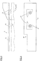
- Figur 4
- einen Längsschnitt durch die Therapieliege, Figur eine Aufsicht auf die Therapieliege mit einem in den Liegenkörper integrierten Spannmittel,
- Figur 6
- eine Seitenansicht der Therapieliege kurz vor dem Auflegen auf das Positioniersystem an der Therapiemaschine und
- Figur 7
- eine Aufsicht auf die Therapieliege und das Positioniersystem, letzteres in gebrochenen Linien dargestellt.
- Mit Bezugszeichen 1 ist ein Transportwagen für eine Therapieliege 3, auch Couch genannt, bezeichnet. Der Transportwagen 1 umfasst beispielsweise einen Kopfteil 5 mit einer Vertikalführung für eine Kupplungsvorrichtung. An der Unterkante des Kopfteils 5 sind zwei ein Fahrgestell bildende, seitlich beabstandet liegende Ausleger 7 mit je zwei Rädern 9 angeordnet sind. Im Kopfteil 5 sind die nicht angetriebene Vertikalführung und eine Kupplungsvorrichtung eingebaut (Vertikalführung und Kupplungsvorrichtung nicht dargestellt). Die Kupplungsvorrichtung dient dazu, einen Kupplungskopf 11, welcher mit der Therapieliege 3 bzw. den die Therapieliege 3 bildenden plattenförmigen Liegenkörpern 13 lösbar verbunden ist, zu tragen. Die Kupplungselemente am Kupplungskopf 11 für die lösbare Verbindung zur Therapieliege sind ebenfalls nicht dargestellt.
- Am Transportwagen 1 können zudem zwei Haltestangen 15 befestigt sein, die um eine Achse A nach unten schwenkbar gelagert sind. Das Kuppeln der Therapieliege 3 an der Vertikalführung erfolgt über einen Hebel 17. Das Lösen der Verbindungskupplung zwischen der Vertikalführung im Kopfteil 5 und dem Kupplungskopf 11 erfolgt ebenfalls mit dem Hebel 17. Der Transportwagen 1 kann an einer Führungsstange 21 von Hand geschoben werden oder, falls erwünscht, sensorgesteuert durch einen elektrischen Antrieb der Räder 9 verfahren werden.
- Der Abstand der beiden Ausleger 7 ist derart gewählt, dass diese beim Heranführen des Transportwagens 1 an eine Diagnostikmaschine 23 bzw. an deren Therapietisch 25 die Liege 3 über den Tisch 25 zu liegen kommen (
Figuren 2 und3 ). Wird der Transportwagen 1 in Richtung des Pfeils P (Figur 2 ) über den Therapietisch 25 geschoben, so liegt die Unterseite der Therapieliege 3 knapp über der Oberfläche 27 des Therapietischs 25. Ist die Endstellung etwa erreicht (Figur 3 ), hebt sich der Therapietisch 25. Durch die Hubbewegung wird die Therapieliege 3 leicht angehoben, was durch die Parallelführung im Kopfteil 5 möglich ist, ohne dass die Liege 3 vom Kopfteil 5 entkuppelt wird. Durch Betätigen des zweiten Hebels 19 wird die Therapieliege 3 auf der Oberfläche des Therapietisches 25 in horizontaler Lage zentriert. Der Zentriermechanismus 29 ist zwischen den beiden Oberflächen, d. h. der oben anliegenden Oberfläche und der untenliegenden Oberfläche, der Therapieliege in die Therapieliege 3 eingebaut und orientiert sich an auf dem Patiententisch 25 angebrachten Kupplungsteilen, z. Bsp. zylindrische Bolzen 31, welche mit dem Anheben des Therapietisches 25 von unten in einen Raum 32 an der Unterseite der Therapieliege 3 hineinragen. In der Unterseite bzw. im Inneren der Therapieliege 3 sind passive Kupplungsteile 35, z.B. hinterschnittene Bereiche ausgebildet, in welche aktive, d.h. aktiv bewegbare Kupplungsteile 37 eingreifen können und z.B. durch eine Spreizbewegung die passiven Kupplungsteile 35 hintergreifen. Durch die Spreizbewegung der aktiven Kupplungsteile 37, die am Therapietisch 25 angeordnet sind, erfolgt nicht nur das Festhalten der Therapieliege 3 auf dem Therapietisch 25, sondern vorab oder gleichzeitig eine absolut genaue reproduzierbare Positionierung der Therapieliege 3 in der horizontalen Ebene. Die beiden Kupplungsteile 35 und 37 bilden somit ein Positioniersystem 33 für die Therapieliege 3. Die passiven und aktiven Kupplungsteile 35,37 sind vorzugsweise aus nicht magnetischen Werkstoffen hergestellt, wodurch die Liege 3 beispielweise auch am MRI eingesetzt werden kann. Mit der erfindungsgemässen Ausbildung und Anordnung der Kupplungsteile 35,37 können an der Therapieliege 3 auch Ausschnitte 39 ausgebildet sein, welche eine optimale Zugänglichkeit der Bestrahlungsmaschine an einem auf der Therapieliege 3 liegenden Patienten ermöglichen. Nach dem Auflegen der Couch/Liege 3 auf den Tisch 25 an der Diagnostikmaschine oder dem Ankuppeln der Couch am Patientenpositioniersystem an der Therapiemaschine wird durch Betätigen des ersten Hebels 17 die Therapieliege 3 vom Kopfteil 5 des Transportwagens 1 getrennt. Der Transportwagen 1 kann nun vom Therapietisch 25 weggeführt werden. - In der Ausgestaltung der Erfindung gemäss
Figuren 6 und 7 ist der passive Kupplungsteil 35 im Liegenkörper 13 der Therapieliege 3 ausgebildet. In dieser Ausgestaltung ist der passive Kupplungsteil 35 ein Hinterschnitt im Raum 32, in welchem aktive Kupplungsteile 37, die am Tisch 23 der Diagnostikmaschine und am Tisch 25 der Therapiemaschine vertikal verschiebbar und horizontal spreizbar ausgebildet sind. Die Betätigung der aktiven Kupplungsteile an den Tischen 23,25 erfolgt durch elektromechanische oder handbetätigte, in den Figuren nicht dargestellte Aktivierungsmittel.
Claims (5)
- System, umfassend eine Therapieliege (3) und eine Transfereinrichtung umfassend einen Transportwagen (1) mit einer Kupplungsvorrichtung für den Transfer der Therapieliege (3) von einem ersten Tisch an einer Diagnostikmaschine zu einem zweiten Tisch an einer Therapiemaschine zur Strahlenbehandlung einer auf der Therapieliege (3) liegenden Person, wobei die Therapieliege (3) einen flachen, plattenförmigen Liegenkörper (13) umfasst, zwischen dessen oben und unten anliegenden Oberflächen ein Raum (32) zum Einführen eines Kupplungsteils (29,37,31) von unten durch die untere Oberfläche des Liegenkörpers (13) und zum Positionieren und zum Festhalten der Therapieliege (3) auf den Tischen (23,25) ausgebildet ist, wobei zwischen den beiden Oberflächen ein Spannelement (29) vorhanden ist, mit dem die Therapieliege (3) an den Tischen der Diagnostik- und Therapiemaschine positionsgenau befestigbar ist, dadurch gekennzeichnet, dass die Therapieliege einen an dem gegenüberliegenden Ende vom Therapiebereich der Liege lösbar angebrachten Kopplungskopf aufweist, welcher mit der Kupplungsvorrichtung des Transportwagens verbindbar ist.
- System nach Anspruch 1, dadurch gekennzeichnet, dass das Kupplungsteil als aktives Kupplungsteil (29, 37) ausgebildet ist.
- System nach Anspruch 2, dadurch gekennzeichnet, dass der Raum (32) derart ausgebildet ist, dass dieser ein passives Kupplungsteil (35) bildet, in welches von unten das aktive Kupplungsteil (37) einfahrbar und zum Positionieren und Festhalten spreizbar ausgebildet ist.
- System nach Anspruch 2, dadurch gekennzeichnet, dass der Raum (32) derart ausgebildet ist, dass in diesem das aktive Kupplungsteil (29) eingesetzt ist, welches an ein von unten einfahrbares passives Kupplungsteil (31) zum Positionieren und Festhalten angreift.
- System nach einem der Ansprüche 1 bis 4, dadurch gekennzeichnet, dass die Therapieliege (3) einen Fussteil (5) umfasst, mit welchem die Therapieliege (3) kopfseitig am Transportwagen (1) festgehalten, getragen und zum Entkuppeln passiv vertikal bewegbar ist.
Applications Claiming Priority (2)
| Application Number | Priority Date | Filing Date | Title |
|---|---|---|---|
| CH02003/13A CH708922A1 (de) | 2013-12-04 | 2013-12-04 | Transfereinrichtung für eine Therapieliege. |
| PCT/CH2014/000164 WO2015081452A1 (de) | 2013-12-04 | 2014-11-14 | Transfereinrichtung für eine therapieliege |
Publications (2)
| Publication Number | Publication Date |
|---|---|
| EP3076874A1 EP3076874A1 (de) | 2016-10-12 |
| EP3076874B1 true EP3076874B1 (de) | 2021-03-24 |
Family
ID=52006766
Family Applications (1)
| Application Number | Title | Priority Date | Filing Date |
|---|---|---|---|
| EP14806526.1A Not-in-force EP3076874B1 (de) | 2013-12-04 | 2014-11-14 | Transfereinrichtung für eine therapieliege |
Country Status (5)
| Country | Link |
|---|---|
| US (1) | US20160296387A1 (de) |
| EP (1) | EP3076874B1 (de) |
| CN (1) | CN106028940A (de) |
| CH (1) | CH708922A1 (de) |
| WO (1) | WO2015081452A1 (de) |
Families Citing this family (5)
| Publication number | Priority date | Publication date | Assignee | Title |
|---|---|---|---|---|
| DE102016113050B4 (de) * | 2016-07-15 | 2019-07-04 | MAQUET GmbH | Zubehörteil mit Klemmbefestigung und Schnittstelle |
| US11304865B2 (en) * | 2017-06-27 | 2022-04-19 | Stryker Corporation | Patient support apparatus with adaptive user interface |
| US12186253B2 (en) | 2021-01-19 | 2025-01-07 | University Of Utah Research Foundation | Trauma gurney with enhanced patient transfer capabilities |
| WO2023020292A1 (en) * | 2021-08-16 | 2023-02-23 | Shanghai United Imaging Healthcare Co., Ltd. | Systems and methods for optimizing medical imaging management |
| DE102024208269A1 (de) | 2024-08-30 | 2025-09-18 | Siemens Healthineers Ag | Komponente für ein medizinisches Bildgebungsgerät mit einer Spannvorrichtung |
Family Cites Families (53)
| Publication number | Priority date | Publication date | Assignee | Title |
|---|---|---|---|---|
| US2891755A (en) * | 1955-10-03 | 1959-06-23 | Gen Electric | Mounting ear in slotted opening |
| US3001755A (en) * | 1959-06-22 | 1961-09-26 | Bell Telephone Labor Inc | Fastening device |
| US2995762A (en) * | 1960-01-18 | 1961-08-15 | Miller Herman Inc | Appointments for beds |
| US3584321A (en) * | 1969-09-12 | 1971-06-15 | Donald L Buchanan | Hydraulic positioning bed for radioisotope scanning |
| US4049230A (en) * | 1976-02-06 | 1977-09-20 | Minniear Carl E | Bracket device |
| US4180247A (en) * | 1977-05-20 | 1979-12-25 | Anchor Post Products, Inc. | Chain link fabric attaching system |
| US4573273A (en) * | 1985-02-07 | 1986-03-04 | Hein-Werner Corporation | Connector for a vehicle measuring system |
| US4707003A (en) * | 1986-09-05 | 1987-11-17 | Read Donald L | Releasable lock mechanism |
| NL8802874A (nl) * | 1988-11-22 | 1990-06-18 | Philips Nv | Patient positionerings en -transportsysteem, alsmede patienttafel, trolley en tafelblad voor toepassing in een dergelijk systeem. |
| US5117521A (en) * | 1990-05-16 | 1992-06-02 | Hill-Rom Company, Inc. | Care cart and transport system |
| US5337845A (en) * | 1990-05-16 | 1994-08-16 | Hill-Rom Company, Inc. | Ventilator, care cart and motorized transport each capable of nesting within and docking with a hospital bed base |
| US5335651A (en) * | 1990-05-16 | 1994-08-09 | Hill-Rom Company, Inc. | Ventilator and care cart each capable of nesting within and docking with a hospital bed base |
| DE4224036C1 (en) * | 1992-07-21 | 1993-05-27 | Siemens Ag, 8000 Muenchen, De | Hospital patient support arrangement - has patient support plate transferable from trolley to bearing support plate on medical appts. table |
| GB9310057D0 (en) * | 1993-05-15 | 1993-06-30 | Smiths Industries Plc | Operating tables,trolleys and transfer systems |
| DE4423374C2 (de) * | 1994-07-04 | 2000-01-05 | Maquet Ag | Verbindungseinrichtung zum wahlweisen Verbinden einer Patientenlagerfläche mit der Stützsäule eines Operationstisches |
| GB9416888D0 (en) * | 1994-08-20 | 1994-10-12 | Smiths Industries Plc | Patient support systems |
| DE19514305C2 (de) * | 1995-04-18 | 2002-12-05 | Maquet Gmbh & Co Kg | Mobiles Patientenlagersystem |
| US5934282A (en) * | 1996-02-13 | 1999-08-10 | Robert Mark Young, III | Hinged spine board |
| US5933321A (en) * | 1996-10-18 | 1999-08-03 | Compaq Computer Corporation | Portable computer docking station having modular motorized docking/undocking structure |
| US5829146A (en) * | 1996-12-30 | 1998-11-03 | Grabber Manufacturing Co., Inc. | Automotive measuring device hanger |
| DE19732467C2 (de) * | 1997-07-28 | 1999-05-27 | Siemens Ag | Transportwagen-Patiententisch-System zum Wechseln einer Wechselplatte sowie Transportwagen für dieses System |
| AU8697998A (en) * | 1997-08-08 | 1999-03-01 | Hill-Rom, Inc. | Proning bed |
| EP1100425A4 (de) * | 1998-06-26 | 2002-10-16 | Hill Rom Co Inc | Bett zur rotqtion eines patienten |
| ES2215813T3 (es) * | 2001-03-05 | 2004-10-16 | Brainlab Ag | Metodo para crear o actualizar un plan de tratamiento de radiaciones. |
| DE10113855B4 (de) * | 2001-03-21 | 2004-04-29 | Siemens Ag | Medizinische Untersuchungs- und/oder Behandlungseinrichtung mit einem Transportwagen für eine Patientenliege und Transportwagen |
| US6978499B2 (en) * | 2001-05-25 | 2005-12-27 | Hill-Rom Services, Inc. | Architectural bed docking apparatus |
| US6640364B1 (en) * | 2001-11-30 | 2003-11-04 | Ge Medical Systems Global Technololgy Company, Llc | Pedestal for use with patient transport system for multiple imaging systems |
| GB0207977D0 (en) * | 2002-04-05 | 2002-05-15 | Eschmann Holdings Ltd | Surgical table transfer system |
| WO2004000078A1 (en) * | 2002-06-21 | 2003-12-31 | General Devices Co., Inc. | Quick-mount support system for telescoping slide |
| US6749275B2 (en) * | 2002-06-21 | 2004-06-15 | General Devices Co., Inc. | Quick-mount support system for telescoping slide |
| US7478855B2 (en) * | 2003-01-15 | 2009-01-20 | Stryker Corporation | Ambulance cot loading and unloading device |
| TWM249078U (en) * | 2003-12-10 | 2004-11-01 | Wistron Corp | Joint seat with transmission mechanism for releasing the mutual locking with external device |
| US6929339B1 (en) * | 2004-02-26 | 2005-08-16 | General Devices Co., Inc. | Latch controller for quick-mount support for telescoping slide |
| US7126816B2 (en) * | 2004-03-12 | 2006-10-24 | Apple Computer, Inc. | Camera latch |
| US7398571B2 (en) * | 2004-09-24 | 2008-07-15 | Stryker Corporation | Ambulance cot and hydraulic elevating mechanism therefor |
| US20090051184A1 (en) * | 2004-10-07 | 2009-02-26 | Shahid Saleem | Stretchers |
| US7139168B2 (en) * | 2004-10-28 | 2006-11-21 | Hewlett-Packard Development Company, L.P. | Docking station |
| US7640607B2 (en) * | 2005-04-29 | 2010-01-05 | Varian Medical Systems, Inc. | Patient support systems |
| US7869858B2 (en) * | 2005-05-12 | 2011-01-11 | General Electric Company | Patient table system and apparatus |
| US20070020070A1 (en) * | 2005-07-02 | 2007-01-25 | General Electric Company | Positioner docking device for a medical imaging apparatus |
| DE102005054221A1 (de) * | 2005-11-14 | 2007-05-16 | Maquet Gmbh & Co Kg | Patientenlagersystem |
| EP1792595A1 (de) * | 2005-12-02 | 2007-06-06 | Paul Scherrer Institut | Selbstfahrendes Patiententransportsystem |
| WO2007067874A2 (en) * | 2005-12-05 | 2007-06-14 | Ahlman Scott M | Patient single surface system |
| JP4220524B2 (ja) * | 2006-01-31 | 2009-02-04 | 株式会社東芝 | 接続装置 |
| KR100810715B1 (ko) * | 2006-08-18 | 2008-03-07 | 가천의과학대학교 산학협력단 | 의료영상장비에 사용되는 크레이들 이송 장치 |
| US8561226B1 (en) * | 2009-07-01 | 2013-10-22 | Martin Manufacturing Co., Inc. | MRI or imaging transfer table |
| US8468625B2 (en) * | 2010-02-12 | 2013-06-25 | Procure Treatment Centers, Inc. | Patient gurney having configurable registration capabilities |
| US8727138B2 (en) * | 2011-11-04 | 2014-05-20 | International Business Machines Corporation | Toolless rail enabling simplified installation and removal |
| EP2809235B1 (de) * | 2012-02-02 | 2018-12-05 | Children's Hospital Medical Center | Mri-transfertischanordnung |
| DE102012110756A1 (de) * | 2012-11-09 | 2014-06-12 | MAQUET GmbH | Transportwagen zum Transport einer Patientenlagerfläche und/oder einer Operationstischsäule eines Operationstischs |
| CN103961132B (zh) * | 2013-01-31 | 2019-01-22 | Ge医疗系统环球技术有限公司 | 床板驱动机构、病床以及患者成像和传送设备 |
| TWI485931B (zh) * | 2013-01-31 | 2015-05-21 | Compal Electronics Inc | 電子設備 |
| US9090275B1 (en) * | 2013-02-08 | 2015-07-28 | Angel M. Feliciano, Jr. | Carrying device |
-
2013
- 2013-12-04 CH CH02003/13A patent/CH708922A1/de not_active Application Discontinuation
-
2014
- 2014-11-14 US US15/100,540 patent/US20160296387A1/en not_active Abandoned
- 2014-11-14 EP EP14806526.1A patent/EP3076874B1/de not_active Not-in-force
- 2014-11-14 CN CN201480066297.XA patent/CN106028940A/zh active Pending
- 2014-11-14 WO PCT/CH2014/000164 patent/WO2015081452A1/de not_active Ceased
Non-Patent Citations (1)
| Title |
|---|
| None * |
Also Published As
| Publication number | Publication date |
|---|---|
| US20160296387A1 (en) | 2016-10-13 |
| CH708922A1 (de) | 2015-06-15 |
| CN106028940A (zh) | 2016-10-12 |
| EP3076874A1 (de) | 2016-10-12 |
| WO2015081452A1 (de) | 2015-06-11 |
Similar Documents
| Publication | Publication Date | Title |
|---|---|---|
| EP3076874B1 (de) | Transfereinrichtung für eine therapieliege | |
| EP1384494B1 (de) | Patientenpositionierungssystem für die Radiotherapie | |
| EP1392169B1 (de) | Patientenlagerungs- und transportsystem | |
| DE102013111523B4 (de) | Röntgenoptimierte Vorrichtung zum Lagern eines Patienten | |
| EP1370178B1 (de) | Medizinische untersuchungs- und/oder behandlungseinrichtung mit einem transportwagen für eine patientenliege und transportwagen | |
| DE10157618A1 (de) | Mehrfachabbildungssystem von Merkmalsmodifikationen | |
| CH457713A (de) | Operationstisch mit ortsfestem Unterteil, mit abhebbarer Liegefläche und Liegeflächentransportwagen | |
| DE102014225519A1 (de) | Vorrichtung und Verfahren zur Unterstützung der Ausrichtung einer an einen OP-Tisch andockbaren Patientenliege | |
| EP3475032B1 (de) | Roboter und roboteranordnung zur patientenpositionierung | |
| DE102010034101B4 (de) | Anordnung für die Strahlentherapie mit einem Haltearm zur Unterstützung diagnostischer Bestrahlung | |
| EP2953534B1 (de) | Anordnung zum vorbereiten und positionieren von medizinisch zu behandelnden und/oder zu versorgenden patienten | |
| DE102016210500A1 (de) | Patientenpositioniervorrichtung und medizinischer Arbeitsplatz | |
| DE10111801B4 (de) | Medizinische Untersuchungs- und/oder Behandlungseinrichtung und Verbund aus mehreren Untersuchungs- und/oder Behandlungsgeräten | |
| WO2015078447A1 (de) | Patiententisch zur herstellung von nmr- und/oder ct-aufnahmen | |
| DE102008005068B4 (de) | Vorrichtung und Verfahren zum Verstellen einer Höhe einer Patientenlagerungs- und Patiententransportvorrichtung, Patientenlagerungs- und Patiententransportvorrichtung sowie medizinische Diagnostik- und/oder Therapieanlage | |
| WO2006099841A1 (de) | Patientenauflage | |
| DE102013208650A1 (de) | Andockvorrichtung | |
| DE102005020687B4 (de) | Magnetresonanzgerät mit einer in einem Untersuchungsraum einbringbaren zweiten Gradientenspuleneinheit | |
| DE202020105591U1 (de) | Koppelsystem zum Ankoppeln einer mobilen Patientenliege | |
| DE19752234A1 (de) | Antriebsvorrichtung für hin- und hergehende Schwenkbewegungen | |
| DE102020125452A1 (de) | Patiententischaufsatz | |
| DE102014114321A1 (de) | Röntgenanwendungsvorrichtung | |
| DE102024202971A1 (de) | Koppelsystem zum Ankoppeln einer mobilen Patientenliege an eine medizinische Bildgebungsanlage | |
| DE202020101356U1 (de) | Patientenlagerungsvorrichtung und Patientenlagerungseinrichtung | |
| DE202006004127U1 (de) | Patientenauflage |
Legal Events
| Date | Code | Title | Description |
|---|---|---|---|
| PUAI | Public reference made under article 153(3) epc to a published international application that has entered the european phase |
Free format text: ORIGINAL CODE: 0009012 |
|
| 17P | Request for examination filed |
Effective date: 20160530 |
|
| AK | Designated contracting states |
Kind code of ref document: A1 Designated state(s): AL AT BE BG CH CY CZ DE DK EE ES FI FR GB GR HR HU IE IS IT LI LT LU LV MC MK MT NL NO PL PT RO RS SE SI SK SM TR |
|
| AX | Request for extension of the european patent |
Extension state: BA ME |
|
| DAX | Request for extension of the european patent (deleted) | ||
| GRAP | Despatch of communication of intention to grant a patent |
Free format text: ORIGINAL CODE: EPIDOSNIGR1 |
|
| STAA | Information on the status of an ep patent application or granted ep patent |
Free format text: STATUS: GRANT OF PATENT IS INTENDED |
|
| INTG | Intention to grant announced |
Effective date: 20200402 |
|
| RIN1 | Information on inventor provided before grant (corrected) |
Inventor name: SCHAER, HUGO |
|
| GRAS | Grant fee paid |
Free format text: ORIGINAL CODE: EPIDOSNIGR3 |
|
| GRAA | (expected) grant |
Free format text: ORIGINAL CODE: 0009210 |
|
| STAA | Information on the status of an ep patent application or granted ep patent |
Free format text: STATUS: THE PATENT HAS BEEN GRANTED |
|
| AK | Designated contracting states |
Kind code of ref document: B1 Designated state(s): AL AT BE BG CH CY CZ DE DK EE ES FI FR GB GR HR HU IE IS IT LI LT LU LV MC MK MT NL NO PL PT RO RS SE SI SK SM TR |
|
| REG | Reference to a national code |
Ref country code: GB Ref legal event code: FG4D Free format text: NOT ENGLISH |
|
| REG | Reference to a national code |
Ref country code: CH Ref legal event code: EP |
|
| REG | Reference to a national code |
Ref country code: DE Ref legal event code: R096 Ref document number: 502014015411 Country of ref document: DE |
|
| REG | Reference to a national code |
Ref country code: IE Ref legal event code: FG4D Free format text: LANGUAGE OF EP DOCUMENT: GERMAN |
|
| REG | Reference to a national code |
Ref country code: AT Ref legal event code: REF Ref document number: 1373655 Country of ref document: AT Kind code of ref document: T Effective date: 20210415 |
|
| REG | Reference to a national code |
Ref country code: LT Ref legal event code: MG9D |
|
| PG25 | Lapsed in a contracting state [announced via postgrant information from national office to epo] |
Ref country code: HR Free format text: LAPSE BECAUSE OF FAILURE TO SUBMIT A TRANSLATION OF THE DESCRIPTION OR TO PAY THE FEE WITHIN THE PRESCRIBED TIME-LIMIT Effective date: 20210324 Ref country code: GR Free format text: LAPSE BECAUSE OF FAILURE TO SUBMIT A TRANSLATION OF THE DESCRIPTION OR TO PAY THE FEE WITHIN THE PRESCRIBED TIME-LIMIT Effective date: 20210625 Ref country code: FI Free format text: LAPSE BECAUSE OF FAILURE TO SUBMIT A TRANSLATION OF THE DESCRIPTION OR TO PAY THE FEE WITHIN THE PRESCRIBED TIME-LIMIT Effective date: 20210324 Ref country code: NO Free format text: LAPSE BECAUSE OF FAILURE TO SUBMIT A TRANSLATION OF THE DESCRIPTION OR TO PAY THE FEE WITHIN THE PRESCRIBED TIME-LIMIT Effective date: 20210624 Ref country code: BG Free format text: LAPSE BECAUSE OF FAILURE TO SUBMIT A TRANSLATION OF THE DESCRIPTION OR TO PAY THE FEE WITHIN THE PRESCRIBED TIME-LIMIT Effective date: 20210624 |
|
| PG25 | Lapsed in a contracting state [announced via postgrant information from national office to epo] |
Ref country code: LV Free format text: LAPSE BECAUSE OF FAILURE TO SUBMIT A TRANSLATION OF THE DESCRIPTION OR TO PAY THE FEE WITHIN THE PRESCRIBED TIME-LIMIT Effective date: 20210324 Ref country code: RS Free format text: LAPSE BECAUSE OF FAILURE TO SUBMIT A TRANSLATION OF THE DESCRIPTION OR TO PAY THE FEE WITHIN THE PRESCRIBED TIME-LIMIT Effective date: 20210324 Ref country code: SE Free format text: LAPSE BECAUSE OF FAILURE TO SUBMIT A TRANSLATION OF THE DESCRIPTION OR TO PAY THE FEE WITHIN THE PRESCRIBED TIME-LIMIT Effective date: 20210324 |
|
| REG | Reference to a national code |
Ref country code: NL Ref legal event code: MP Effective date: 20210324 |
|
| PG25 | Lapsed in a contracting state [announced via postgrant information from national office to epo] |
Ref country code: NL Free format text: LAPSE BECAUSE OF FAILURE TO SUBMIT A TRANSLATION OF THE DESCRIPTION OR TO PAY THE FEE WITHIN THE PRESCRIBED TIME-LIMIT Effective date: 20210324 |
|
| PG25 | Lapsed in a contracting state [announced via postgrant information from national office to epo] |
Ref country code: LT Free format text: LAPSE BECAUSE OF FAILURE TO SUBMIT A TRANSLATION OF THE DESCRIPTION OR TO PAY THE FEE WITHIN THE PRESCRIBED TIME-LIMIT Effective date: 20210324 Ref country code: CZ Free format text: LAPSE BECAUSE OF FAILURE TO SUBMIT A TRANSLATION OF THE DESCRIPTION OR TO PAY THE FEE WITHIN THE PRESCRIBED TIME-LIMIT Effective date: 20210324 Ref country code: EE Free format text: LAPSE BECAUSE OF FAILURE TO SUBMIT A TRANSLATION OF THE DESCRIPTION OR TO PAY THE FEE WITHIN THE PRESCRIBED TIME-LIMIT Effective date: 20210324 Ref country code: SM Free format text: LAPSE BECAUSE OF FAILURE TO SUBMIT A TRANSLATION OF THE DESCRIPTION OR TO PAY THE FEE WITHIN THE PRESCRIBED TIME-LIMIT Effective date: 20210324 |
|
| PG25 | Lapsed in a contracting state [announced via postgrant information from national office to epo] |
Ref country code: IS Free format text: LAPSE BECAUSE OF FAILURE TO SUBMIT A TRANSLATION OF THE DESCRIPTION OR TO PAY THE FEE WITHIN THE PRESCRIBED TIME-LIMIT Effective date: 20210724 Ref country code: SK Free format text: LAPSE BECAUSE OF FAILURE TO SUBMIT A TRANSLATION OF THE DESCRIPTION OR TO PAY THE FEE WITHIN THE PRESCRIBED TIME-LIMIT Effective date: 20210324 Ref country code: RO Free format text: LAPSE BECAUSE OF FAILURE TO SUBMIT A TRANSLATION OF THE DESCRIPTION OR TO PAY THE FEE WITHIN THE PRESCRIBED TIME-LIMIT Effective date: 20210324 Ref country code: PT Free format text: LAPSE BECAUSE OF FAILURE TO SUBMIT A TRANSLATION OF THE DESCRIPTION OR TO PAY THE FEE WITHIN THE PRESCRIBED TIME-LIMIT Effective date: 20210726 Ref country code: PL Free format text: LAPSE BECAUSE OF FAILURE TO SUBMIT A TRANSLATION OF THE DESCRIPTION OR TO PAY THE FEE WITHIN THE PRESCRIBED TIME-LIMIT Effective date: 20210324 Ref country code: ES Free format text: LAPSE BECAUSE OF FAILURE TO SUBMIT A TRANSLATION OF THE DESCRIPTION OR TO PAY THE FEE WITHIN THE PRESCRIBED TIME-LIMIT Effective date: 20210324 |
|
| REG | Reference to a national code |
Ref country code: DE Ref legal event code: R097 Ref document number: 502014015411 Country of ref document: DE |
|
| PG25 | Lapsed in a contracting state [announced via postgrant information from national office to epo] |
Ref country code: DK Free format text: LAPSE BECAUSE OF FAILURE TO SUBMIT A TRANSLATION OF THE DESCRIPTION OR TO PAY THE FEE WITHIN THE PRESCRIBED TIME-LIMIT Effective date: 20210324 Ref country code: AL Free format text: LAPSE BECAUSE OF FAILURE TO SUBMIT A TRANSLATION OF THE DESCRIPTION OR TO PAY THE FEE WITHIN THE PRESCRIBED TIME-LIMIT Effective date: 20210324 |
|
| PLBE | No opposition filed within time limit |
Free format text: ORIGINAL CODE: 0009261 |
|
| STAA | Information on the status of an ep patent application or granted ep patent |
Free format text: STATUS: NO OPPOSITION FILED WITHIN TIME LIMIT |
|
| PG25 | Lapsed in a contracting state [announced via postgrant information from national office to epo] |
Ref country code: SI Free format text: LAPSE BECAUSE OF FAILURE TO SUBMIT A TRANSLATION OF THE DESCRIPTION OR TO PAY THE FEE WITHIN THE PRESCRIBED TIME-LIMIT Effective date: 20210324 |
|
| 26N | No opposition filed |
Effective date: 20220104 |
|
| PG25 | Lapsed in a contracting state [announced via postgrant information from national office to epo] |
Ref country code: IS Free format text: LAPSE BECAUSE OF FAILURE TO SUBMIT A TRANSLATION OF THE DESCRIPTION OR TO PAY THE FEE WITHIN THE PRESCRIBED TIME-LIMIT Effective date: 20210724 |
|
| REG | Reference to a national code |
Ref country code: DE Ref legal event code: R119 Ref document number: 502014015411 Country of ref document: DE |
|
| PG25 | Lapsed in a contracting state [announced via postgrant information from national office to epo] |
Ref country code: MC Free format text: LAPSE BECAUSE OF FAILURE TO SUBMIT A TRANSLATION OF THE DESCRIPTION OR TO PAY THE FEE WITHIN THE PRESCRIBED TIME-LIMIT Effective date: 20210324 |
|
| REG | Reference to a national code |
Ref country code: CH Ref legal event code: PL |
|
| GBPC | Gb: european patent ceased through non-payment of renewal fee |
Effective date: 20211114 |
|
| PG25 | Lapsed in a contracting state [announced via postgrant information from national office to epo] |
Ref country code: LU Free format text: LAPSE BECAUSE OF NON-PAYMENT OF DUE FEES Effective date: 20211114 Ref country code: BE Free format text: LAPSE BECAUSE OF NON-PAYMENT OF DUE FEES Effective date: 20211130 |
|
| REG | Reference to a national code |
Ref country code: BE Ref legal event code: MM Effective date: 20211130 |
|
| PG25 | Lapsed in a contracting state [announced via postgrant information from national office to epo] |
Ref country code: LI Free format text: LAPSE BECAUSE OF NON-PAYMENT OF DUE FEES Effective date: 20211130 Ref country code: CH Free format text: LAPSE BECAUSE OF NON-PAYMENT OF DUE FEES Effective date: 20211130 |
|
| PG25 | Lapsed in a contracting state [announced via postgrant information from national office to epo] |
Ref country code: IE Free format text: LAPSE BECAUSE OF NON-PAYMENT OF DUE FEES Effective date: 20211114 Ref country code: GB Free format text: LAPSE BECAUSE OF NON-PAYMENT OF DUE FEES Effective date: 20211114 Ref country code: DE Free format text: LAPSE BECAUSE OF NON-PAYMENT OF DUE FEES Effective date: 20220601 |
|
| PG25 | Lapsed in a contracting state [announced via postgrant information from national office to epo] |
Ref country code: FR Free format text: LAPSE BECAUSE OF NON-PAYMENT OF DUE FEES Effective date: 20211130 |
|
| REG | Reference to a national code |
Ref country code: AT Ref legal event code: MM01 Ref document number: 1373655 Country of ref document: AT Kind code of ref document: T Effective date: 20211114 |
|
| PG25 | Lapsed in a contracting state [announced via postgrant information from national office to epo] |
Ref country code: IT Free format text: LAPSE BECAUSE OF FAILURE TO SUBMIT A TRANSLATION OF THE DESCRIPTION OR TO PAY THE FEE WITHIN THE PRESCRIBED TIME-LIMIT Effective date: 20210324 Ref country code: AT Free format text: LAPSE BECAUSE OF NON-PAYMENT OF DUE FEES Effective date: 20211114 |
|
| PG25 | Lapsed in a contracting state [announced via postgrant information from national office to epo] |
Ref country code: HU Free format text: LAPSE BECAUSE OF FAILURE TO SUBMIT A TRANSLATION OF THE DESCRIPTION OR TO PAY THE FEE WITHIN THE PRESCRIBED TIME-LIMIT; INVALID AB INITIO Effective date: 20141114 |
|
| PG25 | Lapsed in a contracting state [announced via postgrant information from national office to epo] |
Ref country code: CY Free format text: LAPSE BECAUSE OF FAILURE TO SUBMIT A TRANSLATION OF THE DESCRIPTION OR TO PAY THE FEE WITHIN THE PRESCRIBED TIME-LIMIT Effective date: 20210324 |
|
| PG25 | Lapsed in a contracting state [announced via postgrant information from national office to epo] |
Ref country code: MK Free format text: LAPSE BECAUSE OF FAILURE TO SUBMIT A TRANSLATION OF THE DESCRIPTION OR TO PAY THE FEE WITHIN THE PRESCRIBED TIME-LIMIT Effective date: 20210324 |
|
| PG25 | Lapsed in a contracting state [announced via postgrant information from national office to epo] |
Ref country code: TR Free format text: LAPSE BECAUSE OF FAILURE TO SUBMIT A TRANSLATION OF THE DESCRIPTION OR TO PAY THE FEE WITHIN THE PRESCRIBED TIME-LIMIT Effective date: 20210324 |
|
| PG25 | Lapsed in a contracting state [announced via postgrant information from national office to epo] |
Ref country code: MT Free format text: LAPSE BECAUSE OF FAILURE TO SUBMIT A TRANSLATION OF THE DESCRIPTION OR TO PAY THE FEE WITHIN THE PRESCRIBED TIME-LIMIT Effective date: 20210324 |