EP3079823B1 - Appareil pour distribuer des cellules et procédé - Google Patents
Appareil pour distribuer des cellules et procédé Download PDFInfo
- Publication number
- EP3079823B1 EP3079823B1 EP13810920.2A EP13810920A EP3079823B1 EP 3079823 B1 EP3079823 B1 EP 3079823B1 EP 13810920 A EP13810920 A EP 13810920A EP 3079823 B1 EP3079823 B1 EP 3079823B1
- Authority
- EP
- European Patent Office
- Prior art keywords
- suspension
- needle
- feed vessel
- tubing
- vessel
- Prior art date
- Legal status (The legal status is an assumption and is not a legal conclusion. Google has not performed a legal analysis and makes no representation as to the accuracy of the status listed.)
- Not-in-force
Links
Images


Classifications
-
- B—PERFORMING OPERATIONS; TRANSPORTING
- B01—PHYSICAL OR CHEMICAL PROCESSES OR APPARATUS IN GENERAL
- B01L—CHEMICAL OR PHYSICAL LABORATORY APPARATUS FOR GENERAL USE
- B01L3/00—Containers or dishes for laboratory use, e.g. laboratory glassware; Droppers
- B01L3/02—Burettes; Pipettes
- B01L3/0289—Apparatus for withdrawing or distributing predetermined quantities of fluid
- B01L3/0293—Apparatus for withdrawing or distributing predetermined quantities of fluid for liquids
-
- B—PERFORMING OPERATIONS; TRANSPORTING
- B01—PHYSICAL OR CHEMICAL PROCESSES OR APPARATUS IN GENERAL
- B01L—CHEMICAL OR PHYSICAL LABORATORY APPARATUS FOR GENERAL USE
- B01L3/00—Containers or dishes for laboratory use, e.g. laboratory glassware; Droppers
- B01L3/02—Burettes; Pipettes
- B01L3/021—Pipettes, i.e. with only one conduit for withdrawing and redistributing liquids
-
- B—PERFORMING OPERATIONS; TRANSPORTING
- B01—PHYSICAL OR CHEMICAL PROCESSES OR APPARATUS IN GENERAL
- B01L—CHEMICAL OR PHYSICAL LABORATORY APPARATUS FOR GENERAL USE
- B01L2400/00—Moving or stopping fluids
- B01L2400/04—Moving fluids with specific forces or mechanical means
- B01L2400/0475—Moving fluids with specific forces or mechanical means specific mechanical means and fluid pressure
- B01L2400/0487—Moving fluids with specific forces or mechanical means specific mechanical means and fluid pressure fluid pressure, pneumatics
Definitions
- the present invention relates to the technical field of biological cell cultures and in vitro-tissues and provides means and methods for dispensing a suspension of biological cells for culture.
- cells are obtained, for example, from donor tissue, such as a biopsy, are then isolated and may be cultured for proliferation, conditioning and/or differentiation.
- the cells are brought into suspension in a liquid culture medium.
- the suspension of cells is then dispensed, on culture dishes where the isolated cells are allowed to grow into confluency to finally obtain a novel so called "in vitro" tissue.
- donor tissue such as a biopsy
- the isolated cells are allowed to grow into confluency to finally obtain a novel so called "in vitro" tissue.
- tissue for example, from donor tissue, such as a biopsy
- the cells are brought into suspension in a liquid culture medium.
- the suspension of cells is then dispensed, on culture dishes where the isolated cells are allowed to grow into confluency to finally obtain a novel so called "in vitro" tissue.
- Particular examples are three-dimensional multi-layered tissues comprising one or more layers of cells. These in vitro tissues closely resemble tissue present in mammalian skin.
- a model of the mammalian epidermis comprises layers of keratinocytes; a so called “3D skin equivalent” basically includes a first layer of keratinocytes and a second layer of fibroblast cells embedded in a collagenous biomatrix.
- a first critical aspect in the preparation of such in vitro tissues is the process of initial dispending (or seeding) of isolated cells, in particular of isolated keratinocytes, onto culture dishes.
- isolated cells For reliable and constant quality of the tissues produced it is required that the isolated cells be dispensed and seeded in substantially the same amount (aliquot) to each culture dish. It is also required that cells are seeded as a high-density suspension to ensure a high number of seeded cells in each culture dish.
- high-density suspensions of cells shall be present in a feed vessel from which equal fraction or aliquots of the suspension are then transferred to a plurality of culture dishes or other receiving vessels such as multi titer plates (MTP), multi well plates (MWP) or culture inserts therein by repeated action of a transferring pipette comprising either (sterile) disposable pipette tips or a cleanable fixed hollow pipette needle. Aliquotation requires the dispension of virtually the same number of cells to each culture vessel.
- Known automated pipetting devices for transfer of liquid media are specifically designed to meter equal volumes.
- each fraction of the suspension to be metered and dispensed is of the same "density", i.e. includes the same number of cells per fraction of volume.
- cell suspensions and in particular suspensions with high density have a tendency to settle within a feed vessel as well as, in a certain extent, within the transferring pipette or needle: With the cells following the gravity gradient and/or due to physical and/or biological processes of cell attraction, which results in a higher density of cells at the bottom and a lower density of cells towards the top of the vessel, i.e. an uneven distribution of cells and cell density occurs in a relatively short period of time.
- a previously known fluid transfer mechanism is described in GB2068115 A . It is thus an object of the present invention to provide means for the automated transfer of cell suspensions from a feed vessel to a plurality of receiver vessels by repeated action over time which provide for a safe aliquotation of the cells, i.e. seeding in equal numbers in each receiver vessel, and avoids the deficiencies noted above.
- the present invention concerns a, in particular fully automatically operable, dispensing device for dispensing liquid suspensions of particles, in particular cell suspensions, more particular cell suspensions of high density.
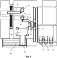
- the device comprises at least one feed vessel containing the stock suspension and at least one, more particular a plurality of receiver vessels for receiving at least one fraction or aliquot of the stock suspension, and at least one transferring means, in particular a pipetting device including a needle, which is moveable relative to the position of the feed vessel to transfer the at least one fraction or aliquot of the stock suspension to the at least one of or to either one of the plurality of receiver vessels.
- the device of the present invention is characterized in that it further comprises a novel re-suspending means located at, and in particular fixed relative to the position of the feed vessel, and is specifically designed for ongoing constant re-suspending action on the stock suspension present in the feed vessel, that is a re-suspension of particles present in the liquid suspension.
- the re-suspending means of the invention comprises a hollow needle and/or a tubing, the tip of which is submersed in the suspension of the feed vessel; the hollow needle and/or tubing is in fluid connection with a pump specifically designed for repeated sucking and expelling of a part of this suspension into and from the needle or tubing to effect re-suspension. While the preferably repeated transferring action of cells from the feed vessel to one or more of the receiver vessels can take place by the transferring means, the present invention pertains that at the same time the re-suspending means can constantly exert re-suspending action within the feed vessel coincidently and in parallel.
- the phrase "re-suspension" and similar as used herein define the process or state where a suspension of particles, and in particular of biological cells, in a liquid medium present in a vessel is brought into or is maintained at a state where its density, i.e. the number of particles or cells at a fraction of the suspension's volume, is constant. A consistent density of the suspension is achieved or maintained for all or most part of the total volume of the suspension, but at least for that part of the volume where the suspension is taken up by the transferring means.
- density i.e. the number of particles or cells at a fraction of the suspension's volume
- the transferring means that is moveable to transfer aliquots of the suspension to receiver vessels is an automated manipulation with at least one axis, more preferred a robot arm, to which an automatic pipette, in particular comprised of at least one hollow needle in fluid connection with at least one pump or metering device for metering the volume of the suspension to be transferred in an embodiment known as such.
- the needle may be of stainless steel or other apt material known in the art and may be fitted to flexible or rigid tubing which establishes fluid connection to the metering device or pump.
- Transferring pipette and robot arm may be operated in a commonly known manner for sequential transfer of suspension from the feed vessel to one or more of the receiver vessel.
- the transferring means of the invention is specifically designed for automated dipping into the feed vessel, then automated uptake of a metered volume of suspension therefrom, then automated retracting of the pipette, and then automated moving of the pipette upon or into one of the receiver vessels, and then automated releasing of metered suspension (or a fraction thereof) onto or into the receiver vessel, and eventually automated returning of the pipette to the feed vessel for repeated performance of these steps.
- the re-suspending means of the present invention more particular comprises a hollow needle which particularly is fitted to a flexible or rigid tubing in a two-pieced arrangement.
- the present invention also concerns an alternative single-pieced arrangement where a flexible or rigid or partially rigid tubing itself forms the tip part which, according to the invention, gets into contact with the suspension within the feed vessel without the need of a separate needle.
- needle in the context of the present invention as used herein refers to both, a stiff hollow needle, preferably made of stainless steel or the like material, and also to a tubing, which is preferably more or less flexible and preferably comprises a chemically inert compound or plastic material, such as a poly-mere, preferably PE, PTFE, PVA, PET, ABC, and others.
- a poly-mere preferably PE, PTFE, PVA, PET, ABC, and others.
- the re-suspending needle comprises a tip which is without any or any significant burr and in particular is radiused and/or rounded to avoid such burrs. This may be accomplished in common manner by cutting the needle with a particular trimming process known as such, which avoids burrs in the first place.
- the tip is thoroughly machined and, alternatively or in addition, polished by an appropriate soft brush, for example, sisal or other soft material to remove burrs eventually present after cutting.
- the needle's tip of the re-suspending means is preferably free of any sharp or cutting edge such as indentation and serration.
- a common steel needle for a transferring pipette cannot be directly used in or to form part of the re-suspending means to accomplish re-suspension according to the present invention.
- the inventors have surprisingly found that a particularly defined and rounded tip of the needle of the re-suspending means is preferred for most of the biological cell types to be re-suspended, albeit particular cell types may exist which are more robust and less prone to mechanical damage.
- the transferring needle of the device of the invention is designed in a common fashion, which particularly includes a conical tip with a sharp tip and a radius increasing towards the shaft.
- the tip of the transferring needle exhibits an inner diameter of 0.5 mm increasing to an inner diameter of about 1.5 mm over the needle's length of several millimeters.
- the outer diameter of the transferring needle also increases given a constant wall thickness.
- the needle's shape at the tip region is typically conical or tapered.
- the tip may comprise a defined shoulder, where the diameter has a sudden rise from the initial approximately 0.5 mm to the final approximately 1.5 mm inner diameter.
- the geometry of the needle of the re-suspending means of the present invention resembles a cylindrical shape with a basically constant diameter at least at the tip part of the needle that is in contact with suspension, but alternatively over the full extent of the needle.
- the present invention preferably provides that at least the tip part the second needle or tubing, which is to be positioned in the suspension is of cylindrical shape.
- the inventors have surprisingly found that due to the provision of a cylindrical shape any turbulence disadvantageous to the cells is avoided during the re-suspending action.
- the re-suspending needle, at least at its cylindrical portion has an inner diameter from about 1 mm to about 2 mm, more preferred of about 1.5 mm.
- the needle of transferring pipette as well as of the re-suspending means may comprise a polished surface on the outside as well as on the inside to facilitate cleaning of the needle, for example by action of ultrasonic waves and detergent to achieve sterility before and/or after getting into contact with the cell suspension.
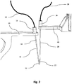
- the needle or tubing of the re-suspending means are located within the feed vessel at the position where a steric hindrance or mechanical interference with the pipette tip or needle of the transferring pipette may occur, such that the re-suspending means is able to rest in place within the feed vessel at least during the constant performance of the re-suspension action, while at the same time, the transferring pipette may repeatedly dip into or retract from the same feed vessel to accomplish the transfer.
- the tip of the needle of the re-suspending means is located in close vicinity of the place, where the tip of the transferring pipette takes in the suspension for transfer as described herein.
- This is meant to better provide for the uptake of an evenly dense suspension into the transferring needle for transfer, because the re-supending means of the invention is designed to confer and maintain a highly even density at least in vicinity to its tip.
- the tip of the re-suspending needle is around 3 mm or less apart from the tip of the movable transferring needle at the time the transferring needle is sucking in the suspension for transfer. Accordingly, it is preferred that tip of the first, i.e.
- the transferring needle is designed to be positioned within a distance of from 1 mm to 3 mm of the tip of the second, i.e. re-suspending needle in the feed vessel.
- the re-suspending needle may be introduced and positioned into the feed vessel at an angle relative to the moveable transferring needle, the latter being preferably introduced at or parallel to the long axis of the feed vessel in form of a tube.
- the tip of the needle of the re-suspending means rests in close vicinity of the bottom of the feed vessel in order to allow for close to complete emptying to minimize the remaining fraction of suspension within the feed vessel which else may have to be discharged.
- the second, i.e. re-suspending, needle is fixed relative to the feed vessel during the despensing process.
- the needle may well be introduced into the feed vessel or retracted therefrom, preferably by means of a robot arm before and after the despensing process, for example to clean the needle and/ or to replace the feed vessel.
- the feed vessel is moveable relative to the re-suspending needle.
- the phrase "at the position of the feed vessel” or “fixed relative to the position of the feed vessel” in the context of the present invention means that the re-suspending means, in particular the re-suspending needle, is fixed during that period of time when suspension is transferred to one or more of the receiver vessel and when re-suspending action is ongoing.
- the phrase thus does not exclude any time period before it and thereafter when the first i.e. re-suspending needle is initially moveable relative to the feed vessel.
- the re-suspending means further includes a self-contained gas bubble which is present within the hollow needle or tubing and serves to separate an operation liquid, i.e. system fluid, present in the needle or tubing downstream towards the pump, from the suspension present upstream thereof at the tip.
- This gas bubble is specifically designed to dampen and/or separate pressure peaks within the operation fluid from the suspension.
- a small gas bubble may be present to seal the operation liquid of the device from the load volume to be taken in, transferred, and expelled from the pipette.
- the volume of the gas bubble is as small as possible to allow for intimate coupling of the two liquids to insure the accuracy of volume taken in or dispended from the pipette.
- the volume of such separating gas bubbles in known automatic pipette devices is about 10 ⁇ l or less.
- the present invention pertains to a separating gas bubble within the re-suspending means which is at least one order of magnitude larger than that and preferably has a gas volume from about 250 ⁇ l to about 500 ⁇ l, preferably of about 300 ⁇ l.
- the gas bubble exhibits elastic characteristics due to the compressibility of gas. In connection with frictional forces exerted to the downstream suspension along the walls of the needle and frictions due to turbulence particularly on the tip of the needle and in connection with the mass inertness of the suspension this results in a mechanical low-pass system. Without wishing to be bound to the theory, this functions to dampen or cancel out peak movements, in particular pressure peaks, shock waves and the like, which may be present in the operation fluid, but are detrimental to cells present in the suspension.
- the dampening characteristics are dependent all of the above factors, among which the size or volume of the gas bubble can be varied in order to adapt the dampening characteristics to the particular set up.
- the receiver vessel or the plurality thereof may comprise a culture flask, one or more culture dishes or alternatively culture tubes. More particular, a plurality of receiver vessels is comprised on a common multi well or multi titer plate containing, for example, 6, 12, 24 identical wells regularly arranged on a common base.
- the cells in suspension are seeded on the bottom of a well.
- the cells are seeded on a membrane of an "insert" placed within a well in order to provide for a floating or air-lift culture of the cells.
- the feed vessel may be a centrifuge tube, which is preferably directly obtained from a preceding centrifugation step for increase of density.
- the feed vessel preferably comprises a conical or tapered bottom. While this embodiment is preferred, the present invention also concerns alternative embodiments of feed vessels, including common culture flasks or a plurality of feed vessels arranged in particular in a multi well or multi titer plate.
- the present invention preferably avoids and any other known means for suspending or re-suspending of particles or cells in a liquid medium and excludes it from the device.
- These are particular means that confer re-suspension by thorough stirring or shaking of the vessel containing the suspension, for example, a so called "vortex" system or the like. It is considered that the presence and use of such systems in a device of the invention gives rather uncontrollable or unreliable re-suspending results, is detrimental to the action and efforts of the transferring means of the device to transfer the cells, and/or may cause mechanical damage to the cells in suspension.
- the present invention also pertains to a method for automated dispensing of a suspension, in particular a cell suspension, from at least one feed vessel to a plurality of receiver vessels by a means for transferring at least one aliquot of the suspension utilizing the re-suspending means at the position of the feed vessel as described herein.
- the method comprises the steps of: (a) transferring one or more aliquot of the suspension from the feed vessel to one or more of the receiving vessels with a first needle, and (b) repeated sucking in and expelling from a second needle or tubing a partial volume of the suspension present in the feed vessel.
- Steps (a) and (b) are performed simultaneously, that is in particular in parallel: preferably, re-suspending action of step (b) is ongoing while the transferring action of step (a) takes place.
- Step (b) preferably starts shortly before the action of step (a) takes place.
- step (b) is still ongoing and is not stopped before the last aliquot is taken out of the feed vessel by the first needle in step (a).
- the method preferably avoids any re-suspending action by the first, i.e. transferring, needle itself by avoiding any single or repeated expulsion of suspension therefrom back to the feed vessel.
- Re-suspension in step (b) is accomplished by repeated suction and expulsion of a partial volume of the suspension present in the feed vessel.
- the particular volume for repeated suction and expulsion the frequency of the repetition and the flow rate of suction and/or expulsion are selected accordingly. According to a preferred embodiment this volume ranges from about 300 ⁇ l to about 600 ⁇ l and is more particular about 500 ⁇ l.
- Suction and expulsion preferably exhibits a peak flow rate of about 300 to about 500 ⁇ l/s and more particular of about 400 ⁇ l/s.
- these values provide for a safe re-suspending action where the cells are thoroughly and efficiently held in suspension of constant density and, at the same time, are prevented from being damaged due to mechanical stress during the action.
- the above values are particularly selected for the suspension of keratinocytes and may be adapted to slightly different values for other cell types.
- any other known process for suspending or re-suspending of particles or cells in a liquid medium is excluded it from the method of the invention, more particular, thorough stirring or shaking of the feed vessel containing the suspension, in particular at least during action of the transferring needle in step (a).
- the method of the invention preferably forms part of a whole automated process where isolated cells are automatically seeded onto culture vessels for growing tissue cultures.
- cells are obtained, for example from biopsy, and then are isolated. Isolated cells are first cultured in a mono layer culture and are then presented in suspension.
- the process may include at least one amplification step where the density of the cells in suspension is increased by centrifugation.
- a high density cell suspension may be obtained in the bottom part of a centrifuge tube.
- the cell free supernatant obtained may be separated off and some fresh culture medium may be added.
- the re-suspending action according to step (b) may be started and kept ongoing while aliquots of the suspension are automatically transferred to a plurality of culture dishes according to step (a), simultaneously and in parallel.
- the seeding of the cells onto the culture dishes by means of the first, i.e. transferring, needle may be performed as known as such, and its manner of metering may be adapted to the particular type of receiver vessel, i.e. either culture flask, culture dish, multi well plate or insert therein.
- the tip of the transferring needle performs additional particular movements during metering of the suspension at the site of the receiver vessel which may include circular, spiral and/or meandering patterns in order to provide for a more even distribution of the cells seeded onto the culture surface. This is of particular importance in connection with the growing of multi-layered, three-dimensional tissues, where the layers shall be of constant thickness throughout most part of the tissue area and requires an even distribution of cell counts seeded per area.
- step (a) includes the transfer of a single aliquot each time the transferring needle moves from the feed vessel to one receiver vessel.
- the method includes that in step (a) the transferring needle takes up a multiplicity of aliquots (n times a single aliquot) at the feed vessel at once and then transfers one single aliquot to each of a number n of receiver vessels - one after the other - before returning to the feed vessel.
- the present invention also concerns the use of a re-suspending means as described herein for the purpose of providing, that is in particular establishing and maintaining, an even and constant density of cells in suspension present in a feed vessel.
- the invention also pertains to a use, wherein the re-suspending second needle or tubing further includes a self-contained gas bubble located within the needle or tubing to dampen and separate pressure peaks present in an operation liquid from the suspension, in particular to avoid mechanical damage to biological cells present in the suspension.
Landscapes
- Chemical & Material Sciences (AREA)
- Health & Medical Sciences (AREA)
- Clinical Laboratory Science (AREA)
- Chemical Kinetics & Catalysis (AREA)
- Analytical Chemistry (AREA)
- Apparatus Associated With Microorganisms And Enzymes (AREA)
Claims (14)
- Dispositif de dispension pour dispenser une suspension, le dispositif comprenant :une cuve d'alimentation (50) contenant la suspension,au moins un ou une pluralité des cuves réceptrices pour recevoir au moins une partie aliquote de la suspension,une première aiguille creuse (20), mobile par rapport à la position de la cuve d'alimentation pour transférer des parties aliquotes de la suspension aux cuves réceptrices, etune seconde aiguille creuse (10) ou tube à la position de la cuve d'alimentation pour constamment remettre en suspension des particules présentes dans la suspension au niveau de la cuve d'alimentation, la deuxième aiguille creuse ou tube étant en connexion fluidique avec une pompe (70) spécifiquement conçue pour aspirer et expulser de façon répétée la suspension dans et de cette aiguille.
- Dispositif selon la revendication 1, dans lequel la première aiguille creuse est en connexion fluidique avec une pompe de dosage spécifiquement conçue pour doser une ou plusieurs parties aliquotes de la suspension.
- Dispositif selon l'une quelconque des revendications 1 ou 2, dans lequel la seconde aiguille ou tube comprend une bulle de gaz autonome située à l'intérieur de l'aiguille ou du tube pour séparer un liquide de travail, situé en aval vers la pompe, de la suspension en amont de celui-ci, la bulle de gaz étant spécifiquement conçue pour amortir et séparer les pics de pression présents dans le liquide de travail de la suspension.
- Dispositif selon la revendication 3, dans lequel la bulle de gaz dans la seconde aiguille ou le tube a un volume de 250 µl à 500 µl.
- Dispositif selon l'une quelconque des revendications précédentes, dans lequel au moins la partie de pointe de la seconde aiguille ou du tube qui doit être positionnée dans la suspension présente une forme cylindrique et a un diamètre intérieur de 1 mm à 2 mm.
- Dispositif selon l'une quelconque des revendications précédentes, dans lequel la seconde aiguille comprend une pointe exempte de bavures, d'indentations ou de dentelures.
- Dispositif selon l'une quelconque des revendications précédentes, dans lequel la pointe de la première aiguille est conçue pour être positionnée à une distance de 1 mm à 3 mm de la pointe de la seconde aiguille.
- Dispositif selon l'une quelconque des revendications précédentes, dans lequel la cuve réceptrice est choisie parmi un flacon de culture, un plat de culture, un puits d'une plaque multi-puits et un insert de culture cellulaire dans un puits.
- Procédé pour le transfert d'une suspension à partir d'une cuve d'alimentation à une ou plusieurs cuves réceptrices, le procédé comprenant les étapes consistant à :(a) transférer une ou plusieurs parties aliquotes de la suspension à partir de la cuve d'alimentation à une ou plusieurs des cuves réceptrices avec une première aiguille, mobile par rapport à la position de la cuve d'alimentation pour transférer des parties aliquotes de la suspension à partir de la cuve d'alimentation aux cuves réceptrices, et(b) aspirer et expulser de façon répétée un volume partiel de la suspension présente dans la cuve d'alimentation dans et d'une seconde aiguille ou tube à la position de la cuve d'alimentation,dans lequel l'étape (a) et l'étape (b) sont effectuées simultanément.
- Procédé selon la revendication 9, dans lequel la première aiguille est déplacée par rapport à la cuve d'alimentation dans l'étape (a), lorsqu'une seconde aiguille ou tube est maintenu(e) fixe par rapport à la cuve d'alimentation dans l'étape (b).
- Procédé selon la revendication 9 ou 10, dans lequel la première aiguille n'expulse pas de suspension au niveau de la cuve d'alimentation à aucun moment.
- Procédé selon l'une quelconque des revendications 9 à 11, dans lequel le volume partiel dans l'étape (b) comprend de 300 µl à 600 µl à un pic de débit de la suspension de 300 µl/s à 500 µl/s.
- Utilisation d'une seconde aiguille ou tube de resuspension dans le dispositif selon l'une quelconque des revendications 1 à 8, pour maintenir une densité uniforme des particules en suspension présente dans une cuve d'alimentation.
- Utilisation selon la revendication 13, dans lequel la seconde aiguille ou le tube de resuspension en outre comprend une bulle de gaz autonome située à l'intérieur de l'aiguille ou du tube pour amortir et séparer de la suspension les pics de pression présents dans un liquide de travail, pour éviter d'endommager mécaniquement les cellules biologiques présentes dans la suspension.
Applications Claiming Priority (1)
| Application Number | Priority Date | Filing Date | Title |
|---|---|---|---|
| PCT/EP2013/076256 WO2015086066A1 (fr) | 2013-12-11 | 2013-12-11 | Système de distribution de cellules |
Publications (2)
| Publication Number | Publication Date |
|---|---|
| EP3079823A1 EP3079823A1 (fr) | 2016-10-19 |
| EP3079823B1 true EP3079823B1 (fr) | 2018-11-14 |
Family
ID=49816912
Family Applications (1)
| Application Number | Title | Priority Date | Filing Date |
|---|---|---|---|
| EP13810920.2A Not-in-force EP3079823B1 (fr) | 2013-12-11 | 2013-12-11 | Appareil pour distribuer des cellules et procédé |
Country Status (2)
| Country | Link |
|---|---|
| EP (1) | EP3079823B1 (fr) |
| WO (1) | WO2015086066A1 (fr) |
Cited By (1)
| Publication number | Priority date | Publication date | Assignee | Title |
|---|---|---|---|---|
| US12226776B2 (en) | 2021-11-04 | 2025-02-18 | Instrumentation Laboratory Company | Preparing substances in a medical diagnostic system |
Families Citing this family (1)
| Publication number | Priority date | Publication date | Assignee | Title |
|---|---|---|---|---|
| CN108034579B (zh) * | 2017-12-08 | 2024-05-03 | 深圳市博瑞生物科技有限公司 | 上样装置 |
Family Cites Families (3)
| Publication number | Priority date | Publication date | Assignee | Title |
|---|---|---|---|---|
| FR1568072A (fr) * | 1968-01-24 | 1969-05-23 | ||
| SE389972B (sv) * | 1975-03-27 | 1976-11-29 | Autochem Instrument Ab | Anordning for dosering av en vetska till ett provror och for agitering av innehallet i provroret |
| FR2474697B1 (fr) * | 1980-01-28 | 1985-07-26 | Coulter Electronics | Mecanisme de transfert de fluide a plusieurs positions |
-
2013
- 2013-12-11 WO PCT/EP2013/076256 patent/WO2015086066A1/fr not_active Ceased
- 2013-12-11 EP EP13810920.2A patent/EP3079823B1/fr not_active Not-in-force
Non-Patent Citations (1)
| Title |
|---|
| None * |
Cited By (1)
| Publication number | Priority date | Publication date | Assignee | Title |
|---|---|---|---|---|
| US12226776B2 (en) | 2021-11-04 | 2025-02-18 | Instrumentation Laboratory Company | Preparing substances in a medical diagnostic system |
Also Published As
| Publication number | Publication date |
|---|---|
| EP3079823A1 (fr) | 2016-10-19 |
| WO2015086066A1 (fr) | 2015-06-18 |
Similar Documents
| Publication | Publication Date | Title |
|---|---|---|
| KR102705686B1 (ko) | 바이오프로세싱용 시스템 및 방법 | |
| US10058859B2 (en) | Pipette device having a micro-dosing unit | |
| KR20250076673A (ko) | 세포 농축 및 격리 방법 | |
| JP7190149B2 (ja) | 赤血球除去装置、単核球回収器、細胞培養装置、細胞培養システム、細胞培養方法、及び単核球の回収方法 | |
| EP3079823B1 (fr) | Appareil pour distribuer des cellules et procédé | |
| US20250250525A1 (en) | Cell culture vessel and cell culture device | |
| JP2025074131A (ja) | 細胞操作方法 | |
| JP7656868B2 (ja) | 細胞培養装置 | |
| JP5999646B2 (ja) | 自動細胞ハンドリングロボットにおける泡沫除去デバイス | |
| JP2018143168A (ja) | 細胞培養担体 | |
| JPWO2019124540A1 (ja) | 細胞培養装置、培養液アスピレータ及び細胞培養方法 | |
| US20230002718A1 (en) | Automated medium exchange strategy for suspension cells | |
| JP2019154277A (ja) | 細胞培養容器 | |
| JP7139510B2 (ja) | 細胞回収方法及び細胞回収装置 | |
| JP7343881B2 (ja) | 赤血球除去装置、単核球回収器、細胞培養装置、細胞培養システム、細胞培養方法、及び単核球の回収方法 | |
| JP7181200B2 (ja) | 脆弱物保持デバイス | |
| US20250172460A1 (en) | Methods and systems for evaluation of tissue samples | |
| HK40063833A (en) | Cell culture device | |
| CN219136814U (zh) | 细胞培养装置 | |
| HK40056621A (en) | Application of cell culturing apparatus | |
| JP2019162093A (ja) | 血球系細胞の製造方法 | |
| CN113717852A (zh) | 一种生物组织培养液吸液方法及加液方法 | |
| HK40056621B (zh) | 细胞培养装置的应用 | |
| HK40057644A (en) | Red blood cell removal device, mononuclear cell collector, cell culture device, cell culture system | |
| WO2021172581A1 (fr) | Capuchon de distribution de liquide et procédé |
Legal Events
| Date | Code | Title | Description |
|---|---|---|---|
| PUAI | Public reference made under article 153(3) epc to a published international application that has entered the european phase |
Free format text: ORIGINAL CODE: 0009012 |
|
| 17P | Request for examination filed |
Effective date: 20160711 |
|
| AK | Designated contracting states |
Kind code of ref document: A1 Designated state(s): AL AT BE BG CH CY CZ DE DK EE ES FI FR GB GR HR HU IE IS IT LI LT LU LV MC MK MT NL NO PL PT RO RS SE SI SK SM TR |
|
| AX | Request for extension of the european patent |
Extension state: BA ME |
|
| DAX | Request for extension of the european patent (deleted) | ||
| GRAP | Despatch of communication of intention to grant a patent |
Free format text: ORIGINAL CODE: EPIDOSNIGR1 |
|
| INTG | Intention to grant announced |
Effective date: 20180606 |
|
| GRAS | Grant fee paid |
Free format text: ORIGINAL CODE: EPIDOSNIGR3 |
|
| GRAA | (expected) grant |
Free format text: ORIGINAL CODE: 0009210 |
|
| AK | Designated contracting states |
Kind code of ref document: B1 Designated state(s): AL AT BE BG CH CY CZ DE DK EE ES FI FR GB GR HR HU IE IS IT LI LT LU LV MC MK MT NL NO PL PT RO RS SE SI SK SM TR |
|
| RIN1 | Information on inventor provided before grant (corrected) |
Inventor name: TRAUBE, ANDREA Inventor name: TRAUBE, ANDREAS Inventor name: WALTER, MORIZ Inventor name: SCHOBER, LENA |
|
| REG | Reference to a national code |
Ref country code: CH Ref legal event code: EP Ref country code: AT Ref legal event code: REF Ref document number: 1064187 Country of ref document: AT Kind code of ref document: T Effective date: 20181115 |
|
| REG | Reference to a national code |
Ref country code: DE Ref legal event code: R096 Ref document number: 602013046814 Country of ref document: DE |
|
| REG | Reference to a national code |
Ref country code: IE Ref legal event code: FG4D |
|
| REG | Reference to a national code |
Ref country code: NL Ref legal event code: MP Effective date: 20181114 |
|
| REG | Reference to a national code |
Ref country code: LT Ref legal event code: MG4D |
|
| REG | Reference to a national code |
Ref country code: AT Ref legal event code: MK05 Ref document number: 1064187 Country of ref document: AT Kind code of ref document: T Effective date: 20181114 |
|
| PG25 | Lapsed in a contracting state [announced via postgrant information from national office to epo] |
Ref country code: AT Free format text: LAPSE BECAUSE OF FAILURE TO SUBMIT A TRANSLATION OF THE DESCRIPTION OR TO PAY THE FEE WITHIN THE PRESCRIBED TIME-LIMIT Effective date: 20181114 Ref country code: LV Free format text: LAPSE BECAUSE OF FAILURE TO SUBMIT A TRANSLATION OF THE DESCRIPTION OR TO PAY THE FEE WITHIN THE PRESCRIBED TIME-LIMIT Effective date: 20181114 Ref country code: LT Free format text: LAPSE BECAUSE OF FAILURE TO SUBMIT A TRANSLATION OF THE DESCRIPTION OR TO PAY THE FEE WITHIN THE PRESCRIBED TIME-LIMIT Effective date: 20181114 Ref country code: NO Free format text: LAPSE BECAUSE OF FAILURE TO SUBMIT A TRANSLATION OF THE DESCRIPTION OR TO PAY THE FEE WITHIN THE PRESCRIBED TIME-LIMIT Effective date: 20190214 Ref country code: IS Free format text: LAPSE BECAUSE OF FAILURE TO SUBMIT A TRANSLATION OF THE DESCRIPTION OR TO PAY THE FEE WITHIN THE PRESCRIBED TIME-LIMIT Effective date: 20190314 Ref country code: FI Free format text: LAPSE BECAUSE OF FAILURE TO SUBMIT A TRANSLATION OF THE DESCRIPTION OR TO PAY THE FEE WITHIN THE PRESCRIBED TIME-LIMIT Effective date: 20181114 Ref country code: BG Free format text: LAPSE BECAUSE OF FAILURE TO SUBMIT A TRANSLATION OF THE DESCRIPTION OR TO PAY THE FEE WITHIN THE PRESCRIBED TIME-LIMIT Effective date: 20190214 Ref country code: ES Free format text: LAPSE BECAUSE OF FAILURE TO SUBMIT A TRANSLATION OF THE DESCRIPTION OR TO PAY THE FEE WITHIN THE PRESCRIBED TIME-LIMIT Effective date: 20181114 Ref country code: HR Free format text: LAPSE BECAUSE OF FAILURE TO SUBMIT A TRANSLATION OF THE DESCRIPTION OR TO PAY THE FEE WITHIN THE PRESCRIBED TIME-LIMIT Effective date: 20181114 |
|
| PG25 | Lapsed in a contracting state [announced via postgrant information from national office to epo] |
Ref country code: GR Free format text: LAPSE BECAUSE OF FAILURE TO SUBMIT A TRANSLATION OF THE DESCRIPTION OR TO PAY THE FEE WITHIN THE PRESCRIBED TIME-LIMIT Effective date: 20190215 Ref country code: NL Free format text: LAPSE BECAUSE OF FAILURE TO SUBMIT A TRANSLATION OF THE DESCRIPTION OR TO PAY THE FEE WITHIN THE PRESCRIBED TIME-LIMIT Effective date: 20181114 Ref country code: SE Free format text: LAPSE BECAUSE OF FAILURE TO SUBMIT A TRANSLATION OF THE DESCRIPTION OR TO PAY THE FEE WITHIN THE PRESCRIBED TIME-LIMIT Effective date: 20181114 Ref country code: AL Free format text: LAPSE BECAUSE OF FAILURE TO SUBMIT A TRANSLATION OF THE DESCRIPTION OR TO PAY THE FEE WITHIN THE PRESCRIBED TIME-LIMIT Effective date: 20181114 Ref country code: PT Free format text: LAPSE BECAUSE OF FAILURE TO SUBMIT A TRANSLATION OF THE DESCRIPTION OR TO PAY THE FEE WITHIN THE PRESCRIBED TIME-LIMIT Effective date: 20190314 Ref country code: RS Free format text: LAPSE BECAUSE OF FAILURE TO SUBMIT A TRANSLATION OF THE DESCRIPTION OR TO PAY THE FEE WITHIN THE PRESCRIBED TIME-LIMIT Effective date: 20181114 |
|
| PG25 | Lapsed in a contracting state [announced via postgrant information from national office to epo] |
Ref country code: DK Free format text: LAPSE BECAUSE OF FAILURE TO SUBMIT A TRANSLATION OF THE DESCRIPTION OR TO PAY THE FEE WITHIN THE PRESCRIBED TIME-LIMIT Effective date: 20181114 Ref country code: PL Free format text: LAPSE BECAUSE OF FAILURE TO SUBMIT A TRANSLATION OF THE DESCRIPTION OR TO PAY THE FEE WITHIN THE PRESCRIBED TIME-LIMIT Effective date: 20181114 Ref country code: CZ Free format text: LAPSE BECAUSE OF FAILURE TO SUBMIT A TRANSLATION OF THE DESCRIPTION OR TO PAY THE FEE WITHIN THE PRESCRIBED TIME-LIMIT Effective date: 20181114 Ref country code: IT Free format text: LAPSE BECAUSE OF FAILURE TO SUBMIT A TRANSLATION OF THE DESCRIPTION OR TO PAY THE FEE WITHIN THE PRESCRIBED TIME-LIMIT Effective date: 20181114 |
|
| REG | Reference to a national code |
Ref country code: CH Ref legal event code: PL |
|
| REG | Reference to a national code |
Ref country code: DE Ref legal event code: R097 Ref document number: 602013046814 Country of ref document: DE |
|
| PG25 | Lapsed in a contracting state [announced via postgrant information from national office to epo] |
Ref country code: RO Free format text: LAPSE BECAUSE OF FAILURE TO SUBMIT A TRANSLATION OF THE DESCRIPTION OR TO PAY THE FEE WITHIN THE PRESCRIBED TIME-LIMIT Effective date: 20181114 Ref country code: SM Free format text: LAPSE BECAUSE OF FAILURE TO SUBMIT A TRANSLATION OF THE DESCRIPTION OR TO PAY THE FEE WITHIN THE PRESCRIBED TIME-LIMIT Effective date: 20181114 Ref country code: EE Free format text: LAPSE BECAUSE OF FAILURE TO SUBMIT A TRANSLATION OF THE DESCRIPTION OR TO PAY THE FEE WITHIN THE PRESCRIBED TIME-LIMIT Effective date: 20181114 Ref country code: MC Free format text: LAPSE BECAUSE OF FAILURE TO SUBMIT A TRANSLATION OF THE DESCRIPTION OR TO PAY THE FEE WITHIN THE PRESCRIBED TIME-LIMIT Effective date: 20181114 Ref country code: SK Free format text: LAPSE BECAUSE OF FAILURE TO SUBMIT A TRANSLATION OF THE DESCRIPTION OR TO PAY THE FEE WITHIN THE PRESCRIBED TIME-LIMIT Effective date: 20181114 Ref country code: LU Free format text: LAPSE BECAUSE OF NON-PAYMENT OF DUE FEES Effective date: 20181211 |
|
| REG | Reference to a national code |
Ref country code: IE Ref legal event code: MM4A |
|
| PLBE | No opposition filed within time limit |
Free format text: ORIGINAL CODE: 0009261 |
|
| STAA | Information on the status of an ep patent application or granted ep patent |
Free format text: STATUS: NO OPPOSITION FILED WITHIN TIME LIMIT |
|
| REG | Reference to a national code |
Ref country code: BE Ref legal event code: MM Effective date: 20181231 |
|
| 26N | No opposition filed |
Effective date: 20190815 |
|
| GBPC | Gb: european patent ceased through non-payment of renewal fee |
Effective date: 20190214 |
|
| PG25 | Lapsed in a contracting state [announced via postgrant information from national office to epo] |
Ref country code: IE Free format text: LAPSE BECAUSE OF NON-PAYMENT OF DUE FEES Effective date: 20181211 Ref country code: FR Free format text: LAPSE BECAUSE OF NON-PAYMENT OF DUE FEES Effective date: 20190114 Ref country code: SI Free format text: LAPSE BECAUSE OF FAILURE TO SUBMIT A TRANSLATION OF THE DESCRIPTION OR TO PAY THE FEE WITHIN THE PRESCRIBED TIME-LIMIT Effective date: 20181114 |
|
| PG25 | Lapsed in a contracting state [announced via postgrant information from national office to epo] |
Ref country code: BE Free format text: LAPSE BECAUSE OF NON-PAYMENT OF DUE FEES Effective date: 20181231 |
|
| PG25 | Lapsed in a contracting state [announced via postgrant information from national office to epo] |
Ref country code: CH Free format text: LAPSE BECAUSE OF NON-PAYMENT OF DUE FEES Effective date: 20181231 Ref country code: LI Free format text: LAPSE BECAUSE OF NON-PAYMENT OF DUE FEES Effective date: 20181231 |
|
| PG25 | Lapsed in a contracting state [announced via postgrant information from national office to epo] |
Ref country code: GB Free format text: LAPSE BECAUSE OF NON-PAYMENT OF DUE FEES Effective date: 20190214 Ref country code: MT Free format text: LAPSE BECAUSE OF NON-PAYMENT OF DUE FEES Effective date: 20181211 |
|
| PG25 | Lapsed in a contracting state [announced via postgrant information from national office to epo] |
Ref country code: TR Free format text: LAPSE BECAUSE OF FAILURE TO SUBMIT A TRANSLATION OF THE DESCRIPTION OR TO PAY THE FEE WITHIN THE PRESCRIBED TIME-LIMIT Effective date: 20181114 |
|
| PG25 | Lapsed in a contracting state [announced via postgrant information from national office to epo] |
Ref country code: HU Free format text: LAPSE BECAUSE OF FAILURE TO SUBMIT A TRANSLATION OF THE DESCRIPTION OR TO PAY THE FEE WITHIN THE PRESCRIBED TIME-LIMIT; INVALID AB INITIO Effective date: 20131211 Ref country code: MK Free format text: LAPSE BECAUSE OF NON-PAYMENT OF DUE FEES Effective date: 20181114 Ref country code: CY Free format text: LAPSE BECAUSE OF FAILURE TO SUBMIT A TRANSLATION OF THE DESCRIPTION OR TO PAY THE FEE WITHIN THE PRESCRIBED TIME-LIMIT Effective date: 20181114 |
|
| PGFP | Annual fee paid to national office [announced via postgrant information from national office to epo] |
Ref country code: DE Payment date: 20221221 Year of fee payment: 10 |
|
| P01 | Opt-out of the competence of the unified patent court (upc) registered |
Effective date: 20230524 |
|
| REG | Reference to a national code |
Ref country code: DE Ref legal event code: R119 Ref document number: 602013046814 Country of ref document: DE |
|
| PG25 | Lapsed in a contracting state [announced via postgrant information from national office to epo] |
Ref country code: DE Free format text: LAPSE BECAUSE OF NON-PAYMENT OF DUE FEES Effective date: 20240702 |
|
| PG25 | Lapsed in a contracting state [announced via postgrant information from national office to epo] |
Ref country code: DE Free format text: LAPSE BECAUSE OF NON-PAYMENT OF DUE FEES Effective date: 20240702 |