EP3085657A1 - Arrangement and method for aligning guide rails in an elevator shaft - Google Patents
Arrangement and method for aligning guide rails in an elevator shaft Download PDFInfo
- Publication number
- EP3085657A1 EP3085657A1 EP15164765.8A EP15164765A EP3085657A1 EP 3085657 A1 EP3085657 A1 EP 3085657A1 EP 15164765 A EP15164765 A EP 15164765A EP 3085657 A1 EP3085657 A1 EP 3085657A1
- Authority
- EP
- European Patent Office
- Prior art keywords
- guide rails
- elevator shaft
- shaft
- installation platform
- position sensitive
- Prior art date
- Legal status (The legal status is an assumption and is not a legal conclusion. Google has not performed a legal analysis and makes no representation as to the accuracy of the status listed.)
- Granted
Links
Images


Classifications
-
- B—PERFORMING OPERATIONS; TRANSPORTING
- B66—HOISTING; LIFTING; HAULING
- B66B—ELEVATORS; ESCALATORS OR MOVING WALKWAYS
- B66B7/00—Other common features of elevators
- B66B7/02—Guideways; Guides
- B66B7/023—Mounting means therefor
- B66B7/027—Mounting means therefor for mounting auxiliary devices
-
- B—PERFORMING OPERATIONS; TRANSPORTING
- B66—HOISTING; LIFTING; HAULING
- B66B—ELEVATORS; ESCALATORS OR MOVING WALKWAYS
- B66B19/00—Mining-hoist operation
- B66B19/002—Mining-hoist operation installing or exchanging guide rails
-
- B—PERFORMING OPERATIONS; TRANSPORTING
- B66—HOISTING; LIFTING; HAULING
- B66B—ELEVATORS; ESCALATORS OR MOVING WALKWAYS
- B66B7/00—Other common features of elevators
- B66B7/02—Guideways; Guides
- B66B7/023—Mounting means therefor
Definitions
- the invention relates to an arrangement and a method for aligning guide rails in an elevator shaft.
- An elevator comprises an elevator car, lifting machinery, ropes, and a counterweight.
- the elevator car is supported on a transport frame being formed by a sling or a car frame.
- the sling surrounds the elevator car.
- the lifting machinery moves the car upwards and downwards in a vertically extending elevator shaft.
- the sling and thereby also the elevator car are carried by the ropes, which connect the elevator car to the counterweight.
- the sling is further supported with gliding means at guide rails extending in the vertical direction in the elevator shaft.
- the gliding means can comprise rolls rolling on the guide rails or gliding shoes gliding on the guide rails when the elevator car is mowing upwards and downwards in the elevator shaft.
- the guide rails are supported with fastening means on the side wall structures of the elevator shaft.
- the gliding means engaging with the guide rails keep the elevator car in position in the horizontal plane when the elevator car moves upwards and downwards in the elevator shaft.
- the counterweight is supported in a corresponding way on guide rails supported with fastening means on the wall structure of the elevator shaft.
- the elevator car transports people and/or goods between the landings in the building.
- the elevator shaft can be formed so that one or several of the side walls are formed of solid walls and/or so that one or several of the side walls are formed of an open steel structure.
- the guide rails are formed of guide rail elements of a certain length.
- the guide rail elements are connected in the installation phase end-on-end one after the other in the elevator shaft.
- the guide rails are attached to the walls of the elevator shaft with fastening means at fastening points along the height of the guide rails.
- WO publication 2007/135228 discloses a method for installing the guide rails of an elevator.
- a first pair of opposite car guide rail elements is installed starting from the bottom of the shaft.
- a second pair of opposite car guide rails is installed end-on-end with the first pair of opposite car guide rails. The process is continued until all the pairs of opposite car guide rails have been installed.
- the counterweight guide rails are installed in a corresponding manner.
- a laser transmitter is used in connection with each guide rail to align the guide rail in the vertical direction.
- a self-directional laser could be used, which automatically directs the laser beam vertically upwards.
- the laser transmitters are first positioned at the bottom of the shaft when the lowermost section of guide rails is installed.
- An alignment appliance provided with an alignment element is supported on each guide rail at each position where the alignment of the guide rail is to be done.
- the laser beam hits the alignment element, whereby the guide rail can be aligned so that the hitting point of the laser beam is in the middle of the alignment element.
- the laser transmitters are moved stepwise upwards for alignment of the next section of guide rails.
- WO publication 2014/053184 discloses a guide rail straightness measuring system for elevator installations.
- the measuring system comprises at least one plumb line mounted vertically in the elevator shaft adjacent to the guide rail and at least one sensor arrangement to be mounted on a carrier to travel vertically along the guide rail.
- the sensor arrangement comprises a frame, at least one guide shoe connected to the frame for sliding or rolling along the guide surface of the guide rail, a bias means for placing and biasing the frame against the guide surface, and at least one sensor means for sensing the position of the plumb line with respect to the frame.
- An object of the present invention is to present a novel arrangement and method for aligning guide rails in an elevator shaft.
- the elevator shaft has a bottom, a top, side walls, a first direction coinciding with a vertical direction in the elevator shaft, a second direction extending between car guide rails on opposite side walls in the elevator shaft and a third direction extending between a back wall and a front wall in the elevator shaft.
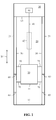
- Figure 1 shows a vertical cross section and figure 2 shows a horizontal cross section of an elevator.
- the elevator comprises a car 10, an elevator shaft 20, a machine room 30, lifting machinery 40, ropes 41, and a counter weight 42.
- the car 10 may be supported on a transport frame 11 or a sling surrounding the car 10.
- the lifting machinery 40 moves the car 10 in a first direction S1 upwards and downwards in a vertically extending elevator shaft 20.
- the sling 11 and thereby also the elevator car 10 are carried by the ropes 41, which connect the elevator car 10 to the counter weight 42.
- the sling 11 and thereby also the elevator car 10 is further supported with gliding means 70 at guide rails 50 extending in the vertical direction in the elevator shaft 20.
- the elevator shaft 20 has a bottom 12, a top 13, a front wall 21A, a back wall 21B, a first side wall 21C and a second opposite side wall 21D.
- the gliding means 70 can comprise rolls rolling on the guide rails 50 or gliding shoes gliding on the guide rails 50 when the elevator car 10 is mowing upwards and downwards in the elevator shaft 20.
- There are further two counter weight guide rails 53, 54 positioned at the back wall 21B of the elevator shaft 20.
- the counter weight 42 is supported with corresponding gliding means 70 on the counter weight guide rails 53, 54.
- the landing doors (not shown in the figure) are positioned in connection with the front wall 21A of the elevator shaft 20.
- Each car guide rail 51, 52 is fastened with fastening means 60 at the respective side wall 21C, 21D of the elevator shaft 20 along the height of the car guide rail 51, 52.
- Each counter weight guide rail 53, 54 is fastened with corresponding fastening means 60 at the back wall 21B of the elevator shaft 20 along the height of the counter weight guide rail 53, 54.
- the figure shows only two fastening means 60, but there are several fastening means 60 along the height of each guide rail 50.
- the cross section of the guide rails 50 can have the form of a letter T.
- the vertical branch of the guide rail element 50 forms three gliding surfaces for the gliding means 70 comprising rolls or gliding shoes.
- the cross-section of the gliding means 70 can have the form of a letter U so that the inner surface of the gliding means 70 sets against the three gliding surfaces of the guide rail 50.
- the gliding means 70 are attached to the sling 11 and/or to the counter weight 42.
- the gliding means 70 engage with the guide rails 50 and keep the elevator car 10 and/or the counter weight 42 in position in the horizontal plane when the elevator car 10 and/or the counter weight 42 moves upwards and downwards in the first direction S1 in the elevator shaft 20.
- the elevator car 10 transports people and/or goods between the landings in the building.
- the elevator shaft 20 can be formed so that all side walls 21, 21A, 21B, 21C, 21D are formed of solid walls or so that one or several of the side walls 21, 21A, 21B, 21C, 21D are formed of an open steel structure.
- the guide rails 50 extend vertically along the height of the elevator shaft 20.
- the guide rails 50 are thus formed of guide rail elements of a certain length e.g. 5 m.
- the guide rail elements 50 are installed end-on-end one after the other.
- Figure 1 shows a first direction S1, which is a vertical direction in the elevator shaft 20.
- Figure 2 shows a second direction S2, which is the direction between the first side wall 21C and the second side wall 21 D in the elevator shaft 20 i.e. the direction between the guide rails (DBG).
- Figure 2 shows further a third direction S3, which is the direction between the back wall 21B and the front wall 21A in the elevator shaft 20 i.e. the back to front direction (BTF).
- the second direction S2 is perpendicular to the third direction S3.
- the second direction S2 and the third direction S3 form a coordinate system in a horizontal plane in the elevator shaft 20.
- Fig. 3 shows an axonometric view of an apparatus for aligning guide rails in an elevator shaft.
- the apparatus 400 for aligning guide rails 50 comprises a positioning unit 100 and an alignment unit 200.
- the positioning unit 100 comprises a longitudinal support structure with a middle portion 110 and two opposite end portions 120, 130.
- the two opposite end portions 120, 130 are mirror images of each other. There could be several middle portions 110 of different lengths in order to adjust the length of the positioning unit 100 to different elevator shafts 20.
- the positioning unit 100 comprises further first attachment means 140, 150 at both ends of the positioning unit 100.
- the first attachment means 140, 150 are movable in the second direction S2 i.e. the direction between the guide rails (DBG).
- the positioning unit 100 extends across the elevator shaft 20 in the second direction S2.
- the first attachment means 140, 150 are used to lock the positioning unit 100 between the wall structures 21 and/or dividing beams and/or brackets 60 in the elevator shaft 20.
- An actuator 141, 151 (position shown only schematically in the figure) e.g. a linear motor in connection with each of the first attachment means 140, 150 can be used to move each of the first attachment means 140, 150 individually in the second direction S2.
- the alignment unit 200 comprises a longitudinal support structure with a middle portion 210 and two opposite end portions 220, 230.
- the two opposite end portions 220, 230 are mirror images of each other.
- the alignment unit comprises further second attachment means 240, 250 at both ends of the alignment unit 200.
- the second attachment means 240, 250 are movable in the second direction S2.
- An actuator 241, 251 e.g. a linear motor can be used to move each of the second attachment means 240, 250 individually in the second direction S2.
- Each of the second attachment means 240, 250 comprises further gripping means in the form of jaws 245, 255 positioned at the end of the second attachment means 240, 250.
- the jaws 245, 255 are movable in the third direction S3 perpendicular to the second direction S2.
- the jaws 245, 255 will thus grip on the opposite side surfaces of the guide rails 50.
- An actuator 246, 256 e.g. a linear motor can be used to move each of the jaws 245, 255 individually in the third direction S3.
- the alignment unit 200 is attached to the positioning unit 100 at each end of the positioning unit 100 with support parts 260, 270.
- the support parts 260, 270 are movable in the third direction S3 in relation to the positioning unit 100.
- the alignment unit 200 is attached with articulated joints J1, J2 to the support parts 260, 270.
- An actuator 261, 271 e.g. a linear motor can be used to move each of the support parts 260, 270 individually in the third direction S3.
- the articulated joints J1, J2 make it possible to adjust the alignment unit 200 so that it is non-parallel to the positioning unit 100.
- the two second attachment means 240, 250 are moved with the actuators 241, 251 only in the second direction S2. It would, however, be possible to add a further actuator to one of the second attachment means 240, 250 in order to be able to turn said second attachment means 240, 250 in the horizontal plane around an articulated joint. It seems that such a possibility is not needed, but such a possibility could be added to the apparatus 500 if needed.
- the apparatus 400 can be operated by a mechanic or automatically by means of a control unit 300.
- the control unit 300 can be attached to the apparatus 400 or it can be a separate entity that is connectable with a cable to the apparatus 400. There can naturally also be a wireless communication between the control unit 300 and the apparatus 400.
- the control unit 300 is used to control all the actuators 141, 142 moving the first attachment means 140, 150, the actuators 241, 242 moving the second attachment means 240, 250, the actuators 246, 256 moving the gripping means 245, 255 and the actuators 261, 271 moving the support parts 260, 270.
- Figure 4 shows a first phase of the operation of the apparatus of figure 3 .
- the guide rails 51, 52 are attached to brackets 65, 66 and the brackets 65, 66 can be attached directly to the side wall 21C of the shaft 20 or through a support bar 68 extending between the back wall 21B and the front wall 21A of the shaft 20.
- the bracket 65 is attached to a bar bracket 61 and the bar bracket 61 is attached to the support bar 68.
- the apparatus 400 can be supported on an installation platform and lifted with the installation platform to a height location of the first fastening means 60 during the alignment of the guide rails 50. A mechanic may be travelling on the installation platform.
- the apparatus 400 may be operated by a mechanic or automatically be means of the control unit 300 so that the alignment unit 200 is controlled to attach with the jaws 245, 255 at the ends of the second attachment means 240, 250 to the two opposite guide rails 51, 52.
- the second attachment means 240, 250 are movable in the second direction S2 and the jaws 245, 255 are movable in the third direction S3 so that they can grip on the opposite vertical side surfaces of the guide rails 51, 52.
- the bolts of the fastening means 60 are then opened at both sides of the shaft 20 so that the guide rails 51, 52 can be moved.
- the guide rails 51, 52 on opposite sides of the shaft 20 are then adjusted relative to each other with the alignment unit 200.
- the frame of the alignment unit 200 is stiff so that the two opposite guide rails 51, 52 will be positioned with the apexes facing towards each other when the gripping means 245, 255 grips the guide rails 50. There is thus no twist between the opposite guide rails 50 after this.
- the distance between the two opposite guide rails 50 in the direction (DBG) is also adjusted with the alignment unit 200.
- the position of each of the second attachment means 240, 250 in the second direction S2 determines said distance.
- the distance in the DBG and the BTF direction from the guide rails 51, 52 to the respective plumb line that is in the vicinity of said guide rail 51, 52 is then determined.
- the needed control values (DBG, BTF and twist) for the apparatus 400 are then calculated.
- the control values are then transformed into incremental steps, which are fed as control signals to the control units of the linear motors in the apparatus 400.
- the DBG can also be measured based on the motor torque, which indicates when the second attachment means 240, 250 have reached their end position and are positioned against the guide rails 50.
- the position of the linear motors can then be read from the display of the control unit 300.
- the apparatus 400 can thus calculate the DBG based on the distance of the guide rails 51, 52 to the plumb lines and based on the position of each of the second attachment means 240, 250 in the second direction S2.
- Figure 5 shows a second phase of the operation of the apparatus of figure 3 .
- the positioning unit 100 of the apparatus 400 is locked to the wall constructions 21 or other support structures in the elevator shaft 20 with the first attachment means 140, 150.
- the alignment unit 200 of the apparatus 400 is in a floating mode in relation to the positioning unit 100 when the positioning unit 100 is locked to the wall construction 21 of the elevator shaft 20.
- the guide rails 51, 52 can now be adjusted with the alignment unit 200 and the positioning unit 100 in relation to the shaft 20.
- the bolts of the fastening means 60 are then tightened.
- the apparatus 400 can now be transported to the next location of the fastening means 60 where the first phase and the second phase of the operation of the apparatus 400 is repeated.
- Figure 6 shows an axonometric view of an elevator shaft showing the principle of the invention.
- the figure shows the apparatus 400 for aligning the guide rails.
- the apparatus 400 for aligning the guide rails is mounted on an installation platform 500 (shown in figures 8-13 ) being arranged to be movable in the first direction S1 upwards and downwards in the elevator shaft 20.
- Each laser transmitter 610, 620, 630, 640 There are four laser transmitters 610, 620, 630, 640 arranged at predetermined positions on the bottom 12 of the elevator shaft 20. Two of the laser transmitters 610, 620 are arranged in the vicinity of the first car guide rail 51 at each side of the first car guide rail 51 and two of the laser transmitters 630, 640 are arranged in the vicinity of the second car guide rail 52 at each side of the second guide rail 52. The position of each laser transmitter 610, 620, 630, 640 in the second direction S2 and in the third direction S3 within the elevator shaft 20 is thus known.
- Each laser transmitter 610, 620, 630, 640 produces a laser beam PL1, PL2, PL3, PL4 which is directed vertically upwards in the elevator shaft 20 and forms a plumb line in the elevator shaft 20.
- the four laser transmitters 610, 620, 630, 640 are positioned on the bottom 12 of the shaft 20, but they can naturally be raised to a higher position in the shaft 20 during the installation if needed. This might be needed in a very high shaft 20 if the laser beam PL1, PL2, PL3, PL4 would not reach through the whole height of the shaft 20.
- the installation could then be done stepwise one section of guide rails 50 at a time.
- the laser transmitters 610, 620, 630, 640 could be raised after the previous section of guide rails have been installed and aligned.
- first position sensitive detectors PSD
- 720, 730, 740 There are further four first position sensitive detectors (PSD) 710, 720, 730, 740 arranged in connection with the apparatus 400 for aligning the guide rails.
- Each of the first PSD:s 710, 720, 730, 740 is arranged so that it receives a respective laser beam PL1, PL2, PL3, PL4.
- the PSD measures the point where the laser beam PL1, PL2, PL3, PL4 hits the position sensitive area of the respective PSD.
- the output signal of each PSD is transferred to a control unit 300 associated with the apparatus 400 for aligning guide rails.
- the position of the apparatus 400 for aligning guide rails in relation to the laser beams PL1, PL2, PL3, PL4 forming the plumb lines in the shaft 20 can thus be determined in the second direction S2 and in the third direction S3 based on the measurements of the PSD:s 710, 720, 730, 740.
- the figure shows further four optional second position sensitive detectors 750, 760, 770, 780 positioned at the top 13 of the elevator shaft 20.
- These second PSD:s 750, 760, 770, 780 can be used as reference sensors in order to be able to detect bending of a high rise building.
- the first position sensitive detectors 710, 720, 730, 740 are in this case transparent sensors with an integrated beam splitter, which means that they let the laser beam PL1, PL2, PL3, PL4 go through so that also the second PSD:s 750, 760, 770, 780 can detect the laser beam PL1, PL2, PL3, PL4.
- the second PSD:s 750, 760, 770, 780 are arranged on the top 13 of the elevator shaft so that each vertically directed laser beam PL1, PL2, PL3, PL4 hits the middle point of a respective second PSD 750, 760, 770, 780 in a situation where the building is straight i.e. there is no wind acting on the building.
- the laser transmitters 610, 620, 630, 640 can be provided with an automatic directing functionality, which can be achieved e.g. with servo motors.
- the orientation of the laser beams PL1, PL2, PL3, PL4 can thus be maintained with the servo motors so that they always point to the middle point of the second PSDs 750, 760, 770, 780.
- the four optional second position sensitive detectors 750, 760, 770, 780 are positioned at the top 13 of the shaft 20, but they can naturally be lowered to a lower position in the shaft 20 during the installation if needed. This might be needed in a very high shaft 20 if the laser beams PL1, PL2, PL3, PL4 would not reach through the whole height of the shaft 20. The installation could then be done stepwise one section of guide rails 50 at a time.
- the second position sensitive detectors 750, 760, 770, 780 could first be positioned in a first position between the installation platform 500 and the top 13 of the shaft 20.
- the second position sensitive detectors 750, 760, 770, 780 could then be raised in synchronism with the raising of the laser transmitters 610, 620, 630, 640.
- Figure 7 shows a vertical cross section of a curved elevator shaft showing the principle of the invention in such a case.
- the bending of the elevator shaft 20 is greatly exaggerated in the figure in order to clarify the situation.
- the figure shows only one laser transmitter 610, one first position sensitive detector 710 and one second position sensitive detector 750.
- the laser beam PL1 produced by the laser transmitter 610 forms a first angle a1 with the vertical direction as said laser beam PL1 is automatically directed to the centre of second position sensitive detector 750.
- the second position sensitive detector 750 is thus not positioned on the vertical line extending upwards from the laser transmitter 610 due to the bending of the elevator shaft 20.
- the laser beam PL1 produced by the laser transmitter 610 hits the first PSD 710 at a first point P1.
- the magnitude and the direction in the second direction S2 and the third direction S3 of the first angle ⁇ 1 of the laser beam PL1 in relation to the vertical direction is known.
- the vertical height H1 distance between the laser transmitter 610 and the second PSD 750 is also known.
- the vertical height position H2 of the first PSD 710 is also known. This information makes it possible to take into consideration the bending of the building.
- a predetermined bending curve BC can be fitted between the laser transmitter 610 and the second PSD 750 so that the bending of the curve follows the bending of the elevator shaft 20.
- the bending curve BC hits the first PSD 710 at a second point P2.
- the second point P2 is thus the corrected hitting point of the laser beam PL1 taking into account the bending of the elevator shaft 20. This correction can be done for all laser beams.
- Figure 8 shows an axonometric view of the alignment of guide rails in an elevator shaft.
- the figure shows the car guide rails 51, 52, the installation platform 500 and the apparatus 400 for aligning the guide rails 51, 52.
- the apparatus 400 for aligning the guide rails 51, 52 is attached with a support arm 450 to a support frame 460 and the support frame 460 is attached to the installation platform 500.
- the apparatus 400 for aligning the guide rails 51, 52 has to be movable in the second direction S2 and in the third direction S3 in relation to the installation platform 500. This can be achieved with one or several joints J10 in the support arm 450.
- the support frame 460 can also be arranged to be movable in the second direction S2 and in the third direction S3.
- Figure 9 shows a horizontal cross section of the elevator shaft showing a first embodiment of the invention.
- the figure shows the installation platform 500, the apparatus 400 for aligning guide rails and two first position sensitive detectors 710, 720 supported on the installation platform 500.
- the installation platform 500 comprises support arms 510, 520, 530, 540 arranged on opposite sides of the installation platform 500 and being movable in a second direction S2 for supporting the installation platform 500 on the opposite side walls 21C, 21D of the shaft 20.
- the gripping means 245, 255 of the second attachment means 240, 250 can grip the opposite guide surfaces of the car guide rails 51, 52.
- the car guide rails 51, 52 can thus be aligned with the apparatus 400 for alignment of guide rails as described earlier in connection with figures 3-5 .
- the installation platform 500 is locked in place with the support arms 510, 520, 530, 540.
- the position of the installation platform 500 in relation to the shaft 20 is determined with the position sensitive detectors 710, 730 once the installation platform 500 is locked in the shaft 20.
- the apparatus 400 is attached to the installation platform 500, whereby the position of the apparatus 400 can be determined indirectly based on the position of them installation platform 500.
- the position of the guide rails 51, 52 can be determined indirectly based on the position of the apparatus 400. This arrangement could be used e.g. in a case where the visibility to the apparatus 400 is restricted so that the first position sensitive detectors 710, 730 cannot be attached to the apparatus 400.
- Figure 10 shows a horizontal cross section of the elevator shaft showing a second embodiment of the invention.
- This second embodiment differs from the first embodiment in that the first position sensitive detectors 710, 730 are attached to the second attachment means 240, 250 in the apparatus 400 for alignment of guide rails.
- the support arms 510, 520, 530, 540 of the installation platform 500 are not shown in the figure.
- the first attachment means 140, 150 of the apparatus 400 for aligning guide rails are used to support the apparatus 400 against the opposite side walls 21C, 21 D in the elevator shaft 20.
- Each guide rail 51, 52 can then be aligned with the second attachment means 250, 250 based on the measurement signals received from the first position sensitive detectors 710, 730 as described in connection with figures 3-5 .
- the position of the apparatus 400 can be determined directly based on the measurement results from the first position sensitive detectors 710, 730 attached to the apparatus 400.
- the position of the guide rails 51, 52 can be determined indirectly based on the position of the apparatus 400.
- Figure 11 shows a horizontal cross section of the elevator shaft showing a third embodiment of the invention.
- This third embodiment differs from the second embodiment in that the first position sensitive detectors 710, 730 are attached via a magnet 715, 735 to a gliding surface the guide rails 51, 52.
- the position of the guide rails 51, 52 can be determined directly based on the measurement results from the first position sensitive detectors 710, 730 attached to the guide rails 51, 52.
- Figure 12 shows a horizontal cross section of the elevator shaft showing a fourth embodiment of the invention.
- This fourth embodiment differs from the second embodiment in that four first position sensitive detectors 710, 720, 730, 740 are used.
- the first two of the first position sensitive detectors 710, 720 are attached to a first of the second attachment means 250 of the apparatus 400 at opposite sides of the first car guide rail 51.
- the second two of the first position sensitive detectors 730, 740 are attached to a second attachment means 240 of the apparatus 500 at opposite sides of the second car guide rail 52.
- the position of the guide rails 51, 52 can be determined based on the position of the second attachment means 240, 250 of the apparatus 400.
- the twist of the car guide rails 51, 52 can easily be measured with this arrangement.
- Figure 13 shows a horizontal cross section of the elevator shaft showing a fifth embodiment of the invention.
- This fifth embodiment differs from the fourth embodiment in that the first position sensitive detectors 710, 720, 730, 740 are attached via a magnet 715, 735 to a gliding surface of the guide rails 51, 52.
- Figure 14 shows a horizontal cross section of a position sensitive detector.
- the position sensitive detector 700 has a centre point C, which forms the centre point for the coordinate system of the position sensitive detector 700.
- the figure shows a hitting point P3 at which the laser beam PL hits the position sensitive detector 700.
- the coordinate X1 of the hitting point P3 in the second direction S2 and the coordinate Y1 of the hitting point P3 in the third direction S3 are given as an output signal by the position sensitive detector 700.
- the idea would then be to change the position of the guide rails 51, 52 so that the laser beam PL hits the position sensitive detector 700 at the centre point C.
- the centre point C of the position sensitive detector 700 is the reference point for the apparatus 400 for aligning guide rails.
- the installation platform 500 may be provided with different installation equipment in addition to the apparatus for aligning guide rails.
- the installation equipment may be used to install guide rails.
- the installation equipment may comprise one or several robots being movable on the installation platform 500.
- the installation platform 500 may be supported with gliding means on the opposite car guide rails 51, 52 during the movement in the first direction S1 upwards and downwards in the elevator shaft 20.
- a hoist may be used to move the installation platform 500 in the first direction S1 upwards and downwards in the elevator shaft 20.
- the PSD could thus e.g. be formed of a detector having an isotropic sensor surface with a raster-like structure that supplies continuous position data.
- the PSD could on the other hand e.g. be formed of a detector having discrete sensors on the sensor surface that supply local discrete data.
- the transfer of information and control data between the first position sensitive detectors 710, 720, 730, 740 and the control unit 300, between the second position sensitive detectors 750, 760, 770, 780 and the control unit 300 and between the laser transmitters 610, 620, 630, 640 and the control unit 300 may be by wireless communication or by wire.
- the transfer of information and control data between the installation platform 500 and the control unit 300 and between the apparatus for alignment 400 and the control unit 300 may be by wireless communication or by wire.
- the height position of the installation platform 500 and/or of the apparatus 400 for aligning guide rails can be measured by any conventional as such known method. This could be done by a laser based distance sensor. Another possibility would be to use an absolute multi turn encoder and a measurement wheel for measuring the movement of the installation platform 500. There could be a reference mark in the shaft 20 at which the encoder could be reset.
- the laser transmitters 610, 620, 630, 640 should be positioned so that the laser beams PL1, PL2, PL3, PL4 can pass freely upwards in the elevator shaft 20 to the first position sensitive detectors 710, 720, 730, 740 and/or to the second position sensitive detectors 750, 760, 770, 780.
- the laser transmitters 610, 620, 630, 640 should be capable of a long range if they are used in a high-rise building. It the working range of the laser emitters 610, 620, 630, 640 is not sufficient for the whole height of the shaft, then the installation could be done in sections so that the laser transmitters 610, 620, 630, 640 are raised between the intervals. Dust or turbulence of the air in the shaft 20 can cause problems at long distances.
- the invention can be used with at least two laser transmitters 610, 620, 630, 640.
- the apparatus 400 for alignment of guide rails shown in figures 3 to 5 is able to align the apexes of the guide rails 51, 52, 53, 54.
- Four laser transmitters 610, 620, 630, 640 are, however, needed in order to measure the straightness of the guide rails 51, 52, 53, 54. This is due to the fact that the guide rails 51, 52, 53, 54 often have some twist.
- the beams L1, L2, L3, L4 of the laser transmitters 610, 620, 630, 640 should be parallel.
- laser beams L1, L2, L3, L4 as plumb lines is advantageous compared to the use of mechanical plumb lines.
- Mechanical plumb lines are formed by wires, which start to vibrate immediately when they are touched by accident. The measurements have to be interrupted until the wire stops vibrating.
- the arrangement and the method can be used in elevator installations where the hoisting height in the elevator shaft is over 30 mm, preferably 30-80 meters, most preferably 40-80 meters.
- the arrangement and the method can on the other hand also be used in elevator installations where the hoisting height in the elevator shaft is over 75 meters, preferably over 100 meters, more preferably over 150 meters, most preferably over 250 meters.
- the installation platform 500 can be used to install car guide rails 51, 52 and/or counter weight guide rails 53, 54.
- the use of the invention is not limited to the type of elevator disclosed in the figures.
- the invention can be used in any type of elevator e.g. also in elevators lacking a machine room and/or a counterweight.
- the counterweight is in the figures positioned on the back wall of the elevator shaft.
- the counterweight could be positioned on either side wall of the shaft or on both side walls of the elevator shaft.
- the lifting machinery is in the figures positioned in a machine room at the top of the elevator shaft.
- the lifting machinery could be positioned at the bottom of the elevator shaft or at some point within the elevator shaft.
Landscapes
- Lift-Guide Devices, And Elevator Ropes And Cables (AREA)
Abstract
Description
- The invention relates to an arrangement and a method for aligning guide rails in an elevator shaft.
- An elevator comprises an elevator car, lifting machinery, ropes, and a counterweight. The elevator car is supported on a transport frame being formed by a sling or a car frame. The sling surrounds the elevator car. The lifting machinery moves the car upwards and downwards in a vertically extending elevator shaft. The sling and thereby also the elevator car are carried by the ropes, which connect the elevator car to the counterweight. The sling is further supported with gliding means at guide rails extending in the vertical direction in the elevator shaft. The gliding means can comprise rolls rolling on the guide rails or gliding shoes gliding on the guide rails when the elevator car is mowing upwards and downwards in the elevator shaft. The guide rails are supported with fastening means on the side wall structures of the elevator shaft. The gliding means engaging with the guide rails keep the elevator car in position in the horizontal plane when the elevator car moves upwards and downwards in the elevator shaft. The counterweight is supported in a corresponding way on guide rails supported with fastening means on the wall structure of the elevator shaft. The elevator car transports people and/or goods between the landings in the building. The elevator shaft can be formed so that one or several of the side walls are formed of solid walls and/or so that one or several of the side walls are formed of an open steel structure.
- The guide rails are formed of guide rail elements of a certain length. The guide rail elements are connected in the installation phase end-on-end one after the other in the elevator shaft. The guide rails are attached to the walls of the elevator shaft with fastening means at fastening points along the height of the guide rails.
-
WO publication 2007/135228 discloses a method for installing the guide rails of an elevator. In the first phase a first pair of opposite car guide rail elements is installed starting from the bottom of the shaft. In the second phase a second pair of opposite car guide rails is installed end-on-end with the first pair of opposite car guide rails. The process is continued until all the pairs of opposite car guide rails have been installed. The counterweight guide rails are installed in a corresponding manner. A laser transmitter is used in connection with each guide rail to align the guide rail in the vertical direction. A self-directional laser could be used, which automatically directs the laser beam vertically upwards. The laser transmitters are first positioned at the bottom of the shaft when the lowermost section of guide rails is installed. An alignment appliance provided with an alignment element is supported on each guide rail at each position where the alignment of the guide rail is to be done. The laser beam hits the alignment element, whereby the guide rail can be aligned so that the hitting point of the laser beam is in the middle of the alignment element. The laser transmitters are moved stepwise upwards for alignment of the next section of guide rails. -
WO publication 2014/053184 discloses a guide rail straightness measuring system for elevator installations. The measuring system comprises at least one plumb line mounted vertically in the elevator shaft adjacent to the guide rail and at least one sensor arrangement to be mounted on a carrier to travel vertically along the guide rail. The sensor arrangement comprises a frame, at least one guide shoe connected to the frame for sliding or rolling along the guide surface of the guide rail, a bias means for placing and biasing the frame against the guide surface, and at least one sensor means for sensing the position of the plumb line with respect to the frame. - An object of the present invention is to present a novel arrangement and method for aligning guide rails in an elevator shaft.
- The arrangement for aligning guide rails in an elevator shaft is defined in
claim 1. - The elevator shaft has a bottom, a top, side walls, a first direction coinciding with a vertical direction in the elevator shaft, a second direction extending between car guide rails on opposite side walls in the elevator shaft and a third direction extending between a back wall and a front wall in the elevator shaft.
- The arrangement is characterised in that:
- an installation platform is arranged to be movable in the first direction upwards and downwards in the elevator shaft, said installation platform being provided with an apparatus for aligning guide rails,
- at least two laser transmitters are arranged at predetermined positions in the shaft below the installation platform, each of said at least two laser transmitters transmitting an upwards directed laser beam that forms a plumb line in the elevator shaft,
- at least two first position sensitive detectors are attached to the installation platform and/or to the apparatus for aligning guide rails and/or to the guide rails, each of said at least two first position sensitive detectors receiving a respective laser beam, whereby the position of the guide rails in relation to the shaft can be determined indirectly or directly.
- The invention will in the following be described in greater detail by means of preferred embodiments with reference to the attached drawings, in which:
-
Figure 1 shows a vertical cross section of an elevator, -
Figure 2 shows a horizontal cross section of the elevator, -
Figure 3 shows an axonometric view of an apparatus for aligning guide rails in an elevator shaft, -
Figure 4 shows a first phase of the operation of the apparatus offigure 3 , -
Figure 5 shows a second phase of the operation of the apparatus offigure 3 . -
Figure 6 shows an axonometric view of an elevator shaft showing the principle of the invention, -
Figure 7 shows a vertical cross section of a curved elevator shaft showing the principle of the invention in such a case, -
Figure 8 shows an axonometric view of the alignment of guide rails in an elevator shaft, -
Figure 9 shows a horizontal cross section of the elevator shaft showing a first embodiment of the invention, -
Figure 10 shows a horizontal cross section of the elevator shaft showing a second embodiment of the invention, -
Figure 11 shows a horizontal cross section of the elevator shaft showing a third embodiment of the invention, -
Figure 12 shows a horizontal cross section of the elevator shaft showing a fourth embodiment of the invention, -
Figure 13 shows a horizontal cross section of the elevator shaft showing a fifth embodiment of the invention, -
Figure 14 shows a horizontal cross section of a position sensitive detector. -
Figure 1 shows a vertical cross section andfigure 2 shows a horizontal cross section of an elevator. - The elevator comprises a
car 10, anelevator shaft 20, amachine room 30,lifting machinery 40,ropes 41, and acounter weight 42. Thecar 10 may be supported on atransport frame 11 or a sling surrounding thecar 10. Thelifting machinery 40 moves thecar 10 in a first direction S1 upwards and downwards in a vertically extendingelevator shaft 20. Thesling 11 and thereby also theelevator car 10 are carried by theropes 41, which connect theelevator car 10 to thecounter weight 42. Thesling 11 and thereby also theelevator car 10 is further supported withgliding means 70 atguide rails 50 extending in the vertical direction in theelevator shaft 20. Theelevator shaft 20 has abottom 12, atop 13, afront wall 21A, aback wall 21B, afirst side wall 21C and a secondopposite side wall 21D. There are twocar guide rails opposite side walls elevator shaft 20. The gliding means 70 can comprise rolls rolling on the guide rails 50 or gliding shoes gliding on the guide rails 50 when theelevator car 10 is mowing upwards and downwards in theelevator shaft 20. There are further two counterweight guide rails back wall 21B of theelevator shaft 20. Thecounter weight 42 is supported with corresponding gliding means 70 on the counterweight guide rails front wall 21A of theelevator shaft 20. - Each
car guide rail respective side wall elevator shaft 20 along the height of thecar guide rail weight guide rail back wall 21B of theelevator shaft 20 along the height of the counterweight guide rail guide rail 50. The cross section of the guide rails 50 can have the form of a letter T. The vertical branch of theguide rail element 50 forms three gliding surfaces for the gliding means 70 comprising rolls or gliding shoes. There are thus two opposite side gliding surfaces and one front gliding surface in theguide rail 50. The cross-section of the gliding means 70 can have the form of a letter U so that the inner surface of the gliding means 70 sets against the three gliding surfaces of theguide rail 50. The gliding means 70 are attached to thesling 11 and/or to thecounter weight 42. - The gliding means 70 engage with the guide rails 50 and keep the
elevator car 10 and/or thecounter weight 42 in position in the horizontal plane when theelevator car 10 and/or thecounter weight 42 moves upwards and downwards in the first direction S1 in theelevator shaft 20. Theelevator car 10 transports people and/or goods between the landings in the building. Theelevator shaft 20 can be formed so that allside walls side walls - The guide rails 50 extend vertically along the height of the
elevator shaft 20. The guide rails 50 are thus formed of guide rail elements of a certain length e.g. 5 m. Theguide rail elements 50 are installed end-on-end one after the other. -
Figure 1 shows a first direction S1, which is a vertical direction in theelevator shaft 20.Figure 2 shows a second direction S2, which is the direction between thefirst side wall 21C and thesecond side wall 21 D in theelevator shaft 20 i.e. the direction between the guide rails (DBG).Figure 2 shows further a third direction S3, which is the direction between theback wall 21B and thefront wall 21A in theelevator shaft 20 i.e. the back to front direction (BTF). The second direction S2 is perpendicular to the third direction S3. The second direction S2 and the third direction S3 form a coordinate system in a horizontal plane in theelevator shaft 20. -
Fig. 3 shows an axonometric view of an apparatus for aligning guide rails in an elevator shaft. Theapparatus 400 for aligningguide rails 50 comprises apositioning unit 100 and analignment unit 200. - The
positioning unit 100 comprises a longitudinal support structure with amiddle portion 110 and twoopposite end portions opposite end portions middle portions 110 of different lengths in order to adjust the length of thepositioning unit 100 todifferent elevator shafts 20. Thepositioning unit 100 comprises further first attachment means 140, 150 at both ends of thepositioning unit 100. The first attachment means 140, 150 are movable in the second direction S2 i.e. the direction between the guide rails (DBG). Thepositioning unit 100 extends across theelevator shaft 20 in the second direction S2. The first attachment means 140, 150 are used to lock thepositioning unit 100 between thewall structures 21 and/or dividing beams and/orbrackets 60 in theelevator shaft 20. Anactuator 141, 151 (position shown only schematically in the figure) e.g. a linear motor in connection with each of the first attachment means 140, 150 can be used to move each of the first attachment means 140, 150 individually in the second direction S2. - The
alignment unit 200 comprises a longitudinal support structure with amiddle portion 210 and twoopposite end portions opposite end portions middle portions 210 of different lengths in order to adjust the length of thealignment unit 200 todifferent elevator shafts 20. The alignment unit comprises further second attachment means 240, 250 at both ends of thealignment unit 200. The second attachment means 240, 250 are movable in the second direction S2. Anactuator jaws jaws jaws actuator jaws alignment unit 200 is attached to thepositioning unit 100 at each end of thepositioning unit 100 withsupport parts support parts positioning unit 100. Thealignment unit 200 is attached with articulated joints J1, J2 to thesupport parts actuator support parts alignment unit 200 so that it is non-parallel to thepositioning unit 100. - The two second attachment means 240, 250 are moved with the
actuators apparatus 500 if needed. - The
apparatus 400 can be operated by a mechanic or automatically by means of acontrol unit 300. Thecontrol unit 300 can be attached to theapparatus 400 or it can be a separate entity that is connectable with a cable to theapparatus 400. There can naturally also be a wireless communication between thecontrol unit 300 and theapparatus 400. Thecontrol unit 300 is used to control all theactuators 141, 142 moving the first attachment means 140, 150, theactuators 241, 242 moving the second attachment means 240, 250, theactuators actuators support parts -
Figure 4 shows a first phase of the operation of the apparatus offigure 3 . The guide rails 51, 52 are attached tobrackets brackets side wall 21C of theshaft 20 or through asupport bar 68 extending between theback wall 21B and thefront wall 21A of theshaft 20. Thebracket 65 is attached to abar bracket 61 and thebar bracket 61 is attached to thesupport bar 68. Theapparatus 400 can be supported on an installation platform and lifted with the installation platform to a height location of the first fastening means 60 during the alignment of the guide rails 50. A mechanic may be travelling on the installation platform. Theapparatus 400 may be operated by a mechanic or automatically be means of thecontrol unit 300 so that thealignment unit 200 is controlled to attach with thejaws opposite guide rails jaws shaft 20 so that the guide rails 51, 52 can be moved. The guide rails 51, 52 on opposite sides of theshaft 20 are then adjusted relative to each other with thealignment unit 200. The frame of thealignment unit 200 is stiff so that the twoopposite guide rails opposite guide rails 50 after this. The distance between the twoopposite guide rails 50 in the direction (DBG) is also adjusted with thealignment unit 200. The position of each of the second attachment means 240, 250 in the second direction S2 determines said distance. - There is a plumb line formed in the vicinity of each
guide rail 51, 52 (not shown in the figure). The distance in the DBG and the BTF direction from the guide rails 51, 52 to the respective plumb line that is in the vicinity of saidguide rail apparatus 400 are then calculated. The control values are then transformed into incremental steps, which are fed as control signals to the control units of the linear motors in theapparatus 400. The DBG can also be measured based on the motor torque, which indicates when the second attachment means 240, 250 have reached their end position and are positioned against the guide rails 50. The position of the linear motors can then be read from the display of thecontrol unit 300. Theapparatus 400 can thus calculate the DBG based on the distance of the guide rails 51, 52 to the plumb lines and based on the position of each of the second attachment means 240, 250 in the second direction S2. -
Figure 5 shows a second phase of the operation of the apparatus offigure 3 . Thepositioning unit 100 of theapparatus 400 is locked to thewall constructions 21 or other support structures in theelevator shaft 20 with the first attachment means 140, 150. Thealignment unit 200 of theapparatus 400 is in a floating mode in relation to thepositioning unit 100 when thepositioning unit 100 is locked to thewall construction 21 of theelevator shaft 20. The guide rails 51, 52 can now be adjusted with thealignment unit 200 and thepositioning unit 100 in relation to theshaft 20. The bolts of the fastening means 60 are then tightened. Theapparatus 400 can now be transported to the next location of the fastening means 60 where the first phase and the second phase of the operation of theapparatus 400 is repeated. -
Figure 6 shows an axonometric view of an elevator shaft showing the principle of the invention. The figure shows theapparatus 400 for aligning the guide rails. Theapparatus 400 for aligning the guide rails is mounted on an installation platform 500 (shown infigures 8-13 ) being arranged to be movable in the first direction S1 upwards and downwards in theelevator shaft 20. - There are four
laser transmitters elevator shaft 20. Two of thelaser transmitters car guide rail 51 at each side of the firstcar guide rail 51 and two of thelaser transmitters car guide rail 52 at each side of thesecond guide rail 52. The position of eachlaser transmitter elevator shaft 20 is thus known. Eachlaser transmitter elevator shaft 20 and forms a plumb line in theelevator shaft 20. The fourlaser transmitters shaft 20, but they can naturally be raised to a higher position in theshaft 20 during the installation if needed. This might be needed in a veryhigh shaft 20 if the laser beam PL1, PL2, PL3, PL4 would not reach through the whole height of theshaft 20. The installation could then be done stepwise one section ofguide rails 50 at a time. Thelaser transmitters - There are further four first position sensitive detectors (PSD) 710, 720, 730, 740 arranged in connection with the
apparatus 400 for aligning the guide rails. Each of thefirst PSD:s control unit 300 associated with theapparatus 400 for aligning guide rails. The position of theapparatus 400 for aligning guide rails in relation to the laser beams PL1, PL2, PL3, PL4 forming the plumb lines in theshaft 20 can thus be determined in the second direction S2 and in the third direction S3 based on the measurements of the PSD:s 710, 720, 730, 740. - The figure shows further four optional second position
sensitive detectors elevator shaft 20. Thesesecond PSD:s sensitive detectors second PSD:s second PSD:s second PSD laser transmitters second PSDs sensitive detectors shaft 20, but they can naturally be lowered to a lower position in theshaft 20 during the installation if needed. This might be needed in a veryhigh shaft 20 if the laser beams PL1, PL2, PL3, PL4 would not reach through the whole height of theshaft 20. The installation could then be done stepwise one section ofguide rails 50 at a time. The second positionsensitive detectors installation platform 500 and the top 13 of theshaft 20. The second positionsensitive detectors laser transmitters -
Figure 7 shows a vertical cross section of a curved elevator shaft showing the principle of the invention in such a case. The bending of theelevator shaft 20 is greatly exaggerated in the figure in order to clarify the situation. The figure shows only onelaser transmitter 610, one first positionsensitive detector 710 and one second positionsensitive detector 750. The laser beam PL1 produced by thelaser transmitter 610 forms a first angle a1 with the vertical direction as said laser beam PL1 is automatically directed to the centre of second positionsensitive detector 750. The second positionsensitive detector 750 is thus not positioned on the vertical line extending upwards from thelaser transmitter 610 due to the bending of theelevator shaft 20. The laser beam PL1 produced by thelaser transmitter 610 hits thefirst PSD 710 at a first point P1. The magnitude and the direction in the second direction S2 and the third direction S3 of the first angle α1 of the laser beam PL1 in relation to the vertical direction is known. The vertical height H1 distance between thelaser transmitter 610 and thesecond PSD 750 is also known. The vertical height position H2 of thefirst PSD 710 is also known. This information makes it possible to take into consideration the bending of the building. A predetermined bending curve BC can be fitted between thelaser transmitter 610 and thesecond PSD 750 so that the bending of the curve follows the bending of theelevator shaft 20. The bending curve BC hits thefirst PSD 710 at a second point P2. The second point P2 is thus the corrected hitting point of the laser beam PL1 taking into account the bending of theelevator shaft 20. This correction can be done for all laser beams. -
Figure 8 shows an axonometric view of the alignment of guide rails in an elevator shaft. The figure shows thecar guide rails installation platform 500 and theapparatus 400 for aligning the guide rails 51, 52. Theapparatus 400 for aligning the guide rails 51, 52 is attached with asupport arm 450 to asupport frame 460 and thesupport frame 460 is attached to theinstallation platform 500. Theapparatus 400 for aligning the guide rails 51, 52 has to be movable in the second direction S2 and in the third direction S3 in relation to theinstallation platform 500. This can be achieved with one or several joints J10 in thesupport arm 450. Thesupport frame 460 can also be arranged to be movable in the second direction S2 and in the third direction S3. -
Figure 9 shows a horizontal cross section of the elevator shaft showing a first embodiment of the invention. The figure shows theinstallation platform 500, theapparatus 400 for aligning guide rails and two first positionsensitive detectors installation platform 500. Theinstallation platform 500 comprisessupport arms installation platform 500 and being movable in a second direction S2 for supporting theinstallation platform 500 on theopposite side walls shaft 20. The gripping means 245, 255 of the second attachment means 240, 250 can grip the opposite guide surfaces of thecar guide rails car guide rails apparatus 400 for alignment of guide rails as described earlier in connection withfigures 3-5 . Theinstallation platform 500 is locked in place with thesupport arms installation platform 500 in relation to theshaft 20 is determined with the positionsensitive detectors installation platform 500 is locked in theshaft 20. When the coordinates of thestationary installation platform 500 are determined, then it is possible to determine the coordinates of theapparatus 400 in relation to theinstallation platform 50 continuously during the alignment procedure. Theapparatus 400 is attached to theinstallation platform 500, whereby the position of theapparatus 400 can be determined indirectly based on the position of theminstallation platform 500. The position of the guide rails 51, 52 can be determined indirectly based on the position of theapparatus 400. This arrangement could be used e.g. in a case where the visibility to theapparatus 400 is restricted so that the first positionsensitive detectors apparatus 400. -
Figure 10 shows a horizontal cross section of the elevator shaft showing a second embodiment of the invention. This second embodiment differs from the first embodiment in that the first positionsensitive detectors apparatus 400 for alignment of guide rails. Thesupport arms installation platform 500 are not shown in the figure. The first attachment means 140, 150 of theapparatus 400 for aligning guide rails are used to support theapparatus 400 against theopposite side walls elevator shaft 20. Eachguide rail sensitive detectors figures 3-5 . The position of theapparatus 400 can be determined directly based on the measurement results from the first positionsensitive detectors apparatus 400. The position of the guide rails 51, 52 can be determined indirectly based on the position of theapparatus 400. -
Figure 11 shows a horizontal cross section of the elevator shaft showing a third embodiment of the invention. This third embodiment differs from the second embodiment in that the first positionsensitive detectors magnet sensitive detectors -
Figure 12 shows a horizontal cross section of the elevator shaft showing a fourth embodiment of the invention. This fourth embodiment differs from the second embodiment in that four first positionsensitive detectors sensitive detectors apparatus 400 at opposite sides of the firstcar guide rail 51. The second two of the first positionsensitive detectors apparatus 500 at opposite sides of the secondcar guide rail 52. The position of the guide rails 51, 52 can be determined based on the position of the second attachment means 240, 250 of theapparatus 400. The twist of thecar guide rails -
Figure 13 shows a horizontal cross section of the elevator shaft showing a fifth embodiment of the invention. This fifth embodiment differs from the fourth embodiment in that the first positionsensitive detectors magnet -
Figure 14 shows a horizontal cross section of a position sensitive detector. The positionsensitive detector 700 has a centre point C, which forms the centre point for the coordinate system of the positionsensitive detector 700. The figure shows a hitting point P3 at which the laser beam PL hits the positionsensitive detector 700. The coordinate X1 of the hitting point P3 in the second direction S2 and the coordinate Y1 of the hitting point P3 in the third direction S3 are given as an output signal by the positionsensitive detector 700. The idea would then be to change the position of the guide rails 51, 52 so that the laser beam PL hits the positionsensitive detector 700 at the centre point C. The centre point C of the positionsensitive detector 700 is the reference point for theapparatus 400 for aligning guide rails. - The
installation platform 500 may be provided with different installation equipment in addition to the apparatus for aligning guide rails. The installation equipment may be used to install guide rails. The installation equipment may comprise one or several robots being movable on theinstallation platform 500. Theinstallation platform 500 may be supported with gliding means on the oppositecar guide rails elevator shaft 20. A hoist may be used to move theinstallation platform 500 in the first direction S1 upwards and downwards in theelevator shaft 20. - The arrangement for aligning guide rails has been described in connection with
car guide rails weight guide rails - Any kind of commercially available position
sensitive detector 700 can be used in the invention. The PSD could thus e.g. be formed of a detector having an isotropic sensor surface with a raster-like structure that supplies continuous position data. The PSD could on the other hand e.g. be formed of a detector having discrete sensors on the sensor surface that supply local discrete data. - The transfer of information and control data between the first position
sensitive detectors control unit 300, between the second positionsensitive detectors control unit 300 and between thelaser transmitters control unit 300 may be by wireless communication or by wire. The transfer of information and control data between theinstallation platform 500 and thecontrol unit 300 and between the apparatus foralignment 400 and thecontrol unit 300 may be by wireless communication or by wire. - The height position of the
installation platform 500 and/or of theapparatus 400 for aligning guide rails can be measured by any conventional as such known method. This could be done by a laser based distance sensor. Another possibility would be to use an absolute multi turn encoder and a measurement wheel for measuring the movement of theinstallation platform 500. There could be a reference mark in theshaft 20 at which the encoder could be reset. - The
laser transmitters elevator shaft 20 to the first positionsensitive detectors sensitive detectors laser transmitters laser emitters laser transmitters shaft 20 can cause problems at long distances. - The invention can be used with at least two
laser transmitters apparatus 400 for alignment of guide rails shown infigures 3 to 5 is able to align the apexes of the guide rails 51, 52, 53, 54. Fourlaser transmitters laser transmitters - The use of laser beams L1, L2, L3, L4 as plumb lines is advantageous compared to the use of mechanical plumb lines. Mechanical plumb lines are formed by wires, which start to vibrate immediately when they are touched by accident. The measurements have to be interrupted until the wire stops vibrating.
- The arrangement and the method can be used in elevator installations where the hoisting height in the elevator shaft is over 30 mm, preferably 30-80 meters, most preferably 40-80 meters.
- The arrangement and the method can on the other hand also be used in elevator installations where the hoisting height in the elevator shaft is over 75 meters, preferably over 100 meters, more preferably over 150 meters, most preferably over 250 meters.
- The
installation platform 500 can be used to installcar guide rails weight guide rails - The use of the invention is not limited to the type of elevator disclosed in the figures. The invention can be used in any type of elevator e.g. also in elevators lacking a machine room and/or a counterweight. The counterweight is in the figures positioned on the back wall of the elevator shaft. The counterweight could be positioned on either side wall of the shaft or on both side walls of the elevator shaft. The lifting machinery is in the figures positioned in a machine room at the top of the elevator shaft. The lifting machinery could be positioned at the bottom of the elevator shaft or at some point within the elevator shaft.
- It will be obvious to a person skilled in the art that, as the technology advances, the inventive concept can be implemented in various ways. The invention and its embodiments are not limited to the examples described above but may vary within the scope of the claims.
Claims (13)
- An arrangement for aligning guide rails (51, 52, 53, 54) in an elevator shaft (20) having a bottom (12), a top (13), side walls (21A, 21B, 21C, 21D), a first direction (S1) coinciding with a vertical direction in the elevator shaft (20), a second direction (S2) extending between car guide rails (51, 52) on opposite side walls (21C, 21D) in the elevator shaft (20) and a third direction (S3) extending between a back wall (21B) and a front wall (21A) in the elevator shaft (20), characterised in that:an installation platform (500) is arranged to be movable in the first direction (S1) upwards and downwards in the elevator shaft (20), said installation platform (500) being provided with an apparatus (400) for aligning guide rails (51, 52, 53, 54),at least two laser transmitters (610, 620, 630, 640) are arranged at predetermined positions in the shaft (20) below the installation platform (500), each of said at least two laser transmitters (610, 620, 630, 640) transmitting an upwards directed laser beam (PL1, PL2, PL3, PL4) that forms a plumb line in the elevator shaft (20),at least two first position sensitive detectors (710, 720, 730, 740) are attached to the installation platform (500) and/or to the apparatus (400) for aligning guide rails (51, 52, 53, 54) and/or to the guide rails (51, 52, 53, 54), each of said at least two first position sensitive detectors (710, 720, 730, 740) receiving a respective laser beam (PL1, PL2, PL3, PL4), whereby the position of the guide rails (51, 52, 53, 54) in relation to the shaft (20) can be determined indirectly or directly.
- An arrangement according to claim 1, characterized in that the installation platform (500) comprises support arms (510, 520, 530, 540) arranged on opposite sides of the installation platform (500) and being movable in a second direction (S2) for supporting the installation platform (500) on the opposite side walls (21C, 21D) of the shaft (20).
- An arrangement according to claim 1 or 2, characterized in that the at least two first position sensitive detectors (710, 720, 730, 740) are attached to the installation platform (500), whereby the position of the installation platform (500) and thereby the position of the guide rails (51, 52, 53, 54) in relation to the elevator shaft (20) can be determined based on the output signals of the at least two first position sensitive detectors (710, 720, 730, 740).
- An arrangement according to claim 1 or 2, characterized in that the at least two first position sensitive detectors (710, 720, 730, 740) are attached to the apparatus (400) for aligning guide rails (51, 52, 53, 54), whereby the position of the apparatus (400) for aligning guide rails (51, 52, 53, 54) and thereby the position of the guide rails (51, 52, 53, 54) in relation to the elevator shaft (20) can be determined based on the output signals of the least two first position sensitive detectors (710, 720, 730, 740).
- An arrangement according to claim 1 or 2, characterized in that the at least two first position sensitive detectors (710, 720, 730, 740) are attached to the guide rails (51, 52, 53, 54), whereby the position of the guide rails (51, 52, 53, 54) in relation to the elevator shaft (20) can be determined based on the output signals of the least two first position sensitive detectors (710, 720, 730, 740).
- An arrangement according to any one of claims 1-5, characterized in that the apparatus (400) for aligning guide rails comprises:a positioning unit (100) extending horizontally across the elevator shaft (20) in the second direction (S2) and comprising first attachment means (140, 150) movable in the second direction (S2) at each end of the positioning unit (100) for supporting the positioning unit (100) on the opposite wall structures (21) of the elevator shaft (20),an alignment unit (200) extending across the elevator shaft (20) in the second direction (S2) and being supported with support parts (260, 270) on each end portion of the positioning unit (100) so that each end portion of the alignment unit (200) is individually movable in relation to the positioning unit (100) in a third direction (S3) perpendicular to the second direction (S2), and comprising second attachment means (240, 250) movable in the second direction (S2) at each end of the alignment unit (200) for supporting the alignment unit (200) on opposite guide rails (50) in the shaft (20), said second attachment means (240, 250) comprising gripping means (245, 255) for gripping on the guide rail (50).
- An arrangement according to claim 6, characterized in that the at least two first position sensitive detectors (710, 720, 730, 740) are attached to the second attachment means (240, 250) of the apparatus (400) for aligning guide rails.
- An arrangement according to any one of claims 1 to 7, characterized in that at least two second position sensitive detectors (750, 760, 770, 780) are arranged in the elevator shaft (20) above the installation platform (500), whereby each laser beam (PL1, PL2, PL3, PL4) of the laser transmitters (610, 620, 630, 640) is automatically and continuously directed towards a centre of a respective second position sensitive detector (750, 760, 770, 780) so that the bending of the elevator shaft (20) can be taken into consideration when the position of the guide rails (51, 52, 53, 54) is determined.
- An arrangement according to any of claims 1 to 8, characterized in that a control unit (300) is arranged to control the movement of the installation platform (500) and the apparatus (400) for aligning guide rails.
- An arrangement according to claim 9, characterized in that the laser transmitters (610, 620, 630, 640) and the control unit (400) are connected so that the angular position of the laser transmitters (610, 620, 630, 640) can be transmitted to the control unit (300).
- An arrangement according to claim 9 or 10, characterized in that the at least two first position sensitive sensors (610, 620, 630, 640) are connected to the control unit (300) so that the output signals of the at least two first position sensitive sensors (610, 620, 630, 640) can be transmitted to the control unit (300).
- A method for aligning guide rails (51, 52, 53, 54) in an elevator shaft (20) having a bottom (12), a top (13), side walls (21A, 21B, 21C, 21D), a first direction (S1) coinciding with a vertical direction in the elevator shaft (20), a second direction (S2) extending between car guide rails (51, 52) on opposite side walls (21C, 21D) in the elevator shaft (20) and a third direction (S3) extending between a back wall (21B) and a front wall (21A) in the elevator shaft (20), characterized by the steps of:arranging an installation platform (500) to be movable in the first direction (S1) upwards and downwards in the elevator shaft (20), said installation platform (500) being provided with an apparatus (400) for aligning guide rails (51, 52, 53, 54),directing at least two laser beams (PL1, PL2, PL3, PL4) from predetermined positions in the shaft (20) below the installation platform (500) upwards in the shaft (20), said at least two laser beams (PL1, PL2, PL3, PL4) forming plumb lines in the shaft (20),attaching at least two first position sensitive sensors (710, 720, 730, 740) to the installation platform (500) and/or to the apparatus (400) for aligning guide rails (51, 52, 53, 54) and/or to the guide rails (51, 52, 53, 54), whereby the at least two position sensitive sensors (710, 720, 730, 740) receive a respective laser beam (PL1, PL2, PL3, PL4), whereby the position of the guide rails (51, 52, 53, 54) in relation to the shaft (20) can be determined indirectly or directly.
- The use of the arrangement according to any one of claims 1 to 11 for aligning guide rails (51, 52, 53, 54) in an elevator shaft (20).
Priority Applications (3)
| Application Number | Priority Date | Filing Date | Title |
|---|---|---|---|
| EP15164765.8A EP3085657B1 (en) | 2015-04-23 | 2015-04-23 | Arrangement and method for aligning guide rails in an elevator shaft |
| US15/090,021 US10315887B2 (en) | 2015-04-23 | 2016-04-04 | Arrangement and method for aligning guide rails in an elevator shaft |
| CN201610258667.0A CN106064774B (en) | 2015-04-23 | 2016-04-22 | Facility and method for alignment track in the elevator shaft |
Applications Claiming Priority (1)
| Application Number | Priority Date | Filing Date | Title |
|---|---|---|---|
| EP15164765.8A EP3085657B1 (en) | 2015-04-23 | 2015-04-23 | Arrangement and method for aligning guide rails in an elevator shaft |
Publications (2)
| Publication Number | Publication Date |
|---|---|
| EP3085657A1 true EP3085657A1 (en) | 2016-10-26 |
| EP3085657B1 EP3085657B1 (en) | 2017-08-23 |
Family
ID=52997963
Family Applications (1)
| Application Number | Title | Priority Date | Filing Date |
|---|---|---|---|
| EP15164765.8A Active EP3085657B1 (en) | 2015-04-23 | 2015-04-23 | Arrangement and method for aligning guide rails in an elevator shaft |
Country Status (3)
| Country | Link |
|---|---|
| US (1) | US10315887B2 (en) |
| EP (1) | EP3085657B1 (en) |
| CN (1) | CN106064774B (en) |
Cited By (5)
| Publication number | Priority date | Publication date | Assignee | Title |
|---|---|---|---|---|
| EP3336040A1 (en) * | 2016-12-19 | 2018-06-20 | KONE Corporation | Arrangement and method for aligning guide rails of an elevator |
| WO2020234005A1 (en) * | 2019-05-21 | 2020-11-26 | Inventio Ag | Aligning device and method for aligning a guide rail of an elevator system by means of force pulses |
| CN112239117A (en) * | 2019-07-16 | 2021-01-19 | 通力股份公司 | Method and device for installing elevator guide rails in elevator shaft |
| EP3967642A1 (en) * | 2020-09-14 | 2022-03-16 | KONE Corporation | An installation platform for installing an elevator during construction of a building |
| GR20230100440A (en) * | 2023-06-01 | 2025-01-20 | ΚΛΕΜΑΝ ΕΛΛΑΣ - (KLEEMANN HELLAS) ΑΝΩΝΥΜΗ ΒΙΟΜΗΧΑΝΙΚΗ ΕΜΠΟΡΙΚΗ ΕΤΑΙΡΕΙΑ ΓΙΑ ΜΗΧΑΝΟΛΟΓΙΚΕΣ ΚΑΤΑΣΚΕΥΕΣ Α.Ε. με δ.τ. ΚΛΕΜΑΝ, | Threads base for elevator installation |
Families Citing this family (23)
| Publication number | Priority date | Publication date | Assignee | Title |
|---|---|---|---|---|
| EP2955145B1 (en) * | 2014-06-13 | 2016-12-21 | KONE Corporation | Apparatus and method for alignment of elevator guide rails |
| US9816796B2 (en) * | 2014-10-09 | 2017-11-14 | Wurtec, Incorporated | Guide rail straightness tester |
| EP3090976B1 (en) * | 2015-05-06 | 2020-03-04 | KONE Corporation | Apparatus and method for aligning guide rails and landing doors in an elevator shaft |
| EP3445697B1 (en) * | 2016-04-20 | 2020-01-22 | Inventio AG | Method and mounting device for carrying out an installation procedure in a lift shaft of a lift assembly |
| CN107187984A (en) * | 2017-07-10 | 2017-09-22 | 合肥康之恒机械科技有限公司 | A kind of safety cargo elevating mechanism |
| WO2019063356A1 (en) * | 2017-09-27 | 2019-04-04 | Inventio Ag | ALIGNMENT DEVICE AND METHOD FOR ASSEMBLING A GUIDE RAIL IN AN ACCESS TRAY OF AN ELEVATOR |
| WO2019063277A1 (en) * | 2017-09-27 | 2019-04-04 | Inventio Ag | LOCALIZATION SYSTEM AND METHOD FOR DETERMINING A CURRENT POSITION IN A RECYCLED TRAIL OF AN ELEVATOR |
| CN108362277B (en) * | 2018-04-03 | 2023-11-21 | 中国建筑第八工程局有限公司 | Profile steel support straightening device and use method thereof |
| CA3092640A1 (en) * | 2018-06-14 | 2019-12-19 | Inventio Ag | Method for erecting a lift facility |
| CN111056402A (en) * | 2018-10-17 | 2020-04-24 | 广州广日电梯工业有限公司 | Adjusting device and adjusting method for elevator guide rail |
| CN109205445B (en) * | 2018-11-23 | 2019-08-02 | 燕山大学 | It is a kind of for install cage guide from climbing robot |
| CN113439065B (en) * | 2019-03-05 | 2023-05-30 | 因温特奥股份公司 | Measuring device for measuring elevator shafts and use of measuring devices for measuring elevator shafts |
| JP6734435B1 (en) * | 2019-04-26 | 2020-08-05 | 東芝エレベータ株式会社 | Jig for elevator rail |
| JP2021095257A (en) * | 2019-12-18 | 2021-06-24 | 株式会社日立ビルシステム | Rail installation device of elevator |
| JP7344161B2 (en) * | 2020-03-16 | 2023-09-13 | 株式会社日立ビルシステム | rail positioning system |
| AU2021241766B2 (en) * | 2020-03-27 | 2024-09-05 | Inventio Ag | Universal console and pit assembly for a rail vehicle of an elevator system, rail system, and method for aligning the rail system |
| JP7027507B1 (en) * | 2020-11-10 | 2022-03-01 | 東芝エレベータ株式会社 | Rail installation support device, rail installation support method, rail installation support system and rail installation support program |
| CN117320993A (en) * | 2021-05-17 | 2023-12-29 | 通力股份公司 | Elevator guide rail alignment methods and devices |
| JP7650721B2 (en) * | 2021-05-20 | 2025-03-25 | 株式会社日立ビルシステム | Template positioning device |
| CN115893164A (en) * | 2022-05-24 | 2023-04-04 | 孙健波 | An elevator guide rail automatic positioning device |
| CN115200550B (en) * | 2022-09-16 | 2022-12-06 | 济宁鲁威液压科技股份有限公司 | Cage guide inclination measuring device and using method thereof |
| US12612741B2 (en) | 2023-02-23 | 2026-04-28 | Tee-Am, L.L.C. | Alignment apparatus |
| CN117125573A (en) * | 2023-09-28 | 2023-11-28 | 日立电梯(上海)有限公司 | An installation and calibration device and method for elevator shaft components |
Citations (4)
| Publication number | Priority date | Publication date | Assignee | Title |
|---|---|---|---|---|
| JPH09221288A (en) * | 1996-02-16 | 1997-08-26 | Hitachi Building Syst Co Ltd | Elevator guide rail centering device |
| CN1587905A (en) * | 2004-10-14 | 2005-03-02 | 上海交通大学 | Detecting robot for lift rail perpendicularity |
| WO2007135228A1 (en) | 2006-05-24 | 2007-11-29 | Kone Corporation | Method for installing the guide rails of an elevator and system for installing the guide rails of an elevator |
| WO2014053184A1 (en) | 2012-10-04 | 2014-04-10 | Kone Corporation | Guide rail straightness measuring system for elevator installations |
Family Cites Families (8)
| Publication number | Priority date | Publication date | Assignee | Title |
|---|---|---|---|---|
| SU552267A1 (en) * | 1975-01-27 | 1977-03-30 | Центральное Проектно-Конструкторское Бюро По Лифтам Всесоюзного Объединения "Союзлифтмаш" | Device for fastening an elevator car cage |
| WO1993023323A1 (en) * | 1992-05-19 | 1993-11-25 | Boral Johns Perry Industries Pty. Ltd. | Guide rail deviation measurement device |
| WO2009073010A1 (en) * | 2007-12-07 | 2009-06-11 | Otis Elevator Company | Methods and devices for surveying elevator hoistways |
| CN201548211U (en) * | 2009-11-19 | 2010-08-11 | 浙江大学 | T-type guide rail straightness automatic detection device |
| FI122066B (en) * | 2009-12-31 | 2011-08-15 | Kone Corp | A method of making a lift |
| EP2733105B1 (en) * | 2012-11-20 | 2020-07-15 | Kone Corporation | Elevator alignment tool |
| CN203550918U (en) * | 2013-09-25 | 2014-04-16 | 常州东方高精新材料股份有限公司 | T-shaped elevator guide rail detection platform |
| EP2993152B8 (en) * | 2014-09-04 | 2017-04-19 | KONE Corporation | Apparatus and method for aligning guide rails in an elevator shaft |
-
2015
- 2015-04-23 EP EP15164765.8A patent/EP3085657B1/en active Active
-
2016
- 2016-04-04 US US15/090,021 patent/US10315887B2/en not_active Expired - Fee Related
- 2016-04-22 CN CN201610258667.0A patent/CN106064774B/en active Active
Patent Citations (4)
| Publication number | Priority date | Publication date | Assignee | Title |
|---|---|---|---|---|
| JPH09221288A (en) * | 1996-02-16 | 1997-08-26 | Hitachi Building Syst Co Ltd | Elevator guide rail centering device |
| CN1587905A (en) * | 2004-10-14 | 2005-03-02 | 上海交通大学 | Detecting robot for lift rail perpendicularity |
| WO2007135228A1 (en) | 2006-05-24 | 2007-11-29 | Kone Corporation | Method for installing the guide rails of an elevator and system for installing the guide rails of an elevator |
| WO2014053184A1 (en) | 2012-10-04 | 2014-04-10 | Kone Corporation | Guide rail straightness measuring system for elevator installations |
Cited By (11)
| Publication number | Priority date | Publication date | Assignee | Title |
|---|---|---|---|---|
| EP3336040A1 (en) * | 2016-12-19 | 2018-06-20 | KONE Corporation | Arrangement and method for aligning guide rails of an elevator |
| US10408608B2 (en) | 2016-12-19 | 2019-09-10 | Kone Corporation | Arrangement and method for aligning guide rails of an elevator |
| WO2020234005A1 (en) * | 2019-05-21 | 2020-11-26 | Inventio Ag | Aligning device and method for aligning a guide rail of an elevator system by means of force pulses |
| US11724917B2 (en) | 2019-05-21 | 2023-08-15 | Inventio Ag | Aligning device and method for aligning a guide rail of an elevator system by means of force pulses |
| CN112239117A (en) * | 2019-07-16 | 2021-01-19 | 通力股份公司 | Method and device for installing elevator guide rails in elevator shaft |
| EP3967642A1 (en) * | 2020-09-14 | 2022-03-16 | KONE Corporation | An installation platform for installing an elevator during construction of a building |
| WO2022053666A1 (en) * | 2020-09-14 | 2022-03-17 | Kone Corporation | An installation platform for installing an elevator during construction of a building |
| CN116057000A (en) * | 2020-09-14 | 2023-05-02 | 通力股份公司 | Mounting platform for installing lifts during building construction |
| US12172866B2 (en) | 2020-09-14 | 2024-12-24 | Kone Corporation | Installation platform for installing an elevator during construction of a building |
| CN116057000B (en) * | 2020-09-14 | 2025-10-28 | 通力股份公司 | Mounting platform for installing lifts during building construction |
| GR20230100440A (en) * | 2023-06-01 | 2025-01-20 | ΚΛΕΜΑΝ ΕΛΛΑΣ - (KLEEMANN HELLAS) ΑΝΩΝΥΜΗ ΒΙΟΜΗΧΑΝΙΚΗ ΕΜΠΟΡΙΚΗ ΕΤΑΙΡΕΙΑ ΓΙΑ ΜΗΧΑΝΟΛΟΓΙΚΕΣ ΚΑΤΑΣΚΕΥΕΣ Α.Ε. με δ.τ. ΚΛΕΜΑΝ, | Threads base for elevator installation |
Also Published As
| Publication number | Publication date |
|---|---|
| CN106064774A (en) | 2016-11-02 |
| EP3085657B1 (en) | 2017-08-23 |
| US20160311658A1 (en) | 2016-10-27 |
| US10315887B2 (en) | 2019-06-11 |
| CN106064774B (en) | 2019-06-04 |
Similar Documents
| Publication | Publication Date | Title |
|---|---|---|
| US10315887B2 (en) | Arrangement and method for aligning guide rails in an elevator shaft | |
| US9828212B2 (en) | Arrangement and a method for measuring the position of an installation platform in an elevator shaft | |
| US9561938B2 (en) | Method and an arrangement for automatic elevator installation | |
| EP3090976B1 (en) | Apparatus and method for aligning guide rails and landing doors in an elevator shaft | |
| US9714156B2 (en) | Apparatus and method for aligning guide rails in an elevator shaft | |
| US9751728B2 (en) | Method and an arrangement for installing elevator guide rails | |
| EP3127847B1 (en) | An arrangement and a method for measuring the position of an installation platform in an elevator shaft | |
| US9957136B2 (en) | Guide rail straightness measuring system for elevator installations | |
| CN105270958B (en) | The equipment and method of alignment for cage guide | |
| US12589975B2 (en) | Method and an arrangement for aligning elevator guide rails | |
| HK1230152A1 (en) | Arrangement and method for aligning guide rails in an elevator shaft | |
| HK1230152B (en) | Arrangement and method for aligning guide rails in an elevator shaft | |
| HK1230564A1 (en) | An arrangement and a method for measuring the position of an installation platform in an elevator shaft | |
| HK1230565A1 (en) | A method and an arrangement for automatic elevator installation | |
| HK1230565B (en) | A method and an arrangement for automatic elevator installation | |
| HK40099649A (en) | A method and an arrangement for aligning elevator guide rails | |
| HK1230564B (en) | An arrangement and a method for measuring the position of an installation platform in an elevator shaft | |
| HK1230572A1 (en) | A method and an arrangement for installing elevator guide rails |
Legal Events
| Date | Code | Title | Description |
|---|---|---|---|
| PUAI | Public reference made under article 153(3) epc to a published international application that has entered the european phase |
Free format text: ORIGINAL CODE: 0009012 |
|
| AK | Designated contracting states |
Kind code of ref document: A1 Designated state(s): AL AT BE BG CH CY CZ DE DK EE ES FI FR GB GR HR HU IE IS IT LI LT LU LV MC MK MT NL NO PL PT RO RS SE SI SK SM TR |
|
| AX | Request for extension of the european patent |
Extension state: BA ME |
|
| 17P | Request for examination filed |
Effective date: 20170125 |
|
| RBV | Designated contracting states (corrected) |
Designated state(s): AL AT BE BG CH CY CZ DE DK EE ES FI FR GB GR HR HU IE IS IT LI LT LU LV MC MK MT NL NO PL PT RO RS SE SI SK SM TR |
|
| GRAP | Despatch of communication of intention to grant a patent |
Free format text: ORIGINAL CODE: EPIDOSNIGR1 |
|
| INTG | Intention to grant announced |
Effective date: 20170321 |
|
| GRAS | Grant fee paid |
Free format text: ORIGINAL CODE: EPIDOSNIGR3 |
|
| GRAA | (expected) grant |
Free format text: ORIGINAL CODE: 0009210 |
|
| RIN1 | Information on inventor provided before grant (corrected) |
Inventor name: KILPELAEINEN, PEKKA |
|
| AK | Designated contracting states |
Kind code of ref document: B1 Designated state(s): AL AT BE BG CH CY CZ DE DK EE ES FI FR GB GR HR HU IE IS IT LI LT LU LV MC MK MT NL NO PL PT RO RS SE SI SK SM TR |
|
| RAP1 | Party data changed (applicant data changed or rights of an application transferred) |
Owner name: KONE CORPORATION |
|
| REG | Reference to a national code |
Ref country code: GB Ref legal event code: FG4D |
|
| REG | Reference to a national code |
Ref country code: CH Ref legal event code: EP |
|
| REG | Reference to a national code |
Ref country code: AT Ref legal event code: REF Ref document number: 921103 Country of ref document: AT Kind code of ref document: T Effective date: 20170915 |
|
| REG | Reference to a national code |
Ref country code: IE Ref legal event code: FG4D |
|
| REG | Reference to a national code |
Ref country code: DE Ref legal event code: R096 Ref document number: 602015004220 Country of ref document: DE |
|
| REG | Reference to a national code |
Ref country code: NL Ref legal event code: MP Effective date: 20170823 |
|
| REG | Reference to a national code |
Ref country code: LT Ref legal event code: MG4D |
|
| REG | Reference to a national code |
Ref country code: AT Ref legal event code: MK05 Ref document number: 921103 Country of ref document: AT Kind code of ref document: T Effective date: 20170823 |
|
| PG25 | Lapsed in a contracting state [announced via postgrant information from national office to epo] |
Ref country code: NO Free format text: LAPSE BECAUSE OF FAILURE TO SUBMIT A TRANSLATION OF THE DESCRIPTION OR TO PAY THE FEE WITHIN THE PRESCRIBED TIME-LIMIT Effective date: 20171123 Ref country code: HR Free format text: LAPSE BECAUSE OF FAILURE TO SUBMIT A TRANSLATION OF THE DESCRIPTION OR TO PAY THE FEE WITHIN THE PRESCRIBED TIME-LIMIT Effective date: 20170823 Ref country code: FI Free format text: LAPSE BECAUSE OF FAILURE TO SUBMIT A TRANSLATION OF THE DESCRIPTION OR TO PAY THE FEE WITHIN THE PRESCRIBED TIME-LIMIT Effective date: 20170823 Ref country code: LT Free format text: LAPSE BECAUSE OF FAILURE TO SUBMIT A TRANSLATION OF THE DESCRIPTION OR TO PAY THE FEE WITHIN THE PRESCRIBED TIME-LIMIT Effective date: 20170823 Ref country code: NL Free format text: LAPSE BECAUSE OF FAILURE TO SUBMIT A TRANSLATION OF THE DESCRIPTION OR TO PAY THE FEE WITHIN THE PRESCRIBED TIME-LIMIT Effective date: 20170823 Ref country code: SE Free format text: LAPSE BECAUSE OF FAILURE TO SUBMIT A TRANSLATION OF THE DESCRIPTION OR TO PAY THE FEE WITHIN THE PRESCRIBED TIME-LIMIT Effective date: 20170823 Ref country code: AT Free format text: LAPSE BECAUSE OF FAILURE TO SUBMIT A TRANSLATION OF THE DESCRIPTION OR TO PAY THE FEE WITHIN THE PRESCRIBED TIME-LIMIT Effective date: 20170823 |
|
| PG25 | Lapsed in a contracting state [announced via postgrant information from national office to epo] |
Ref country code: GR Free format text: LAPSE BECAUSE OF FAILURE TO SUBMIT A TRANSLATION OF THE DESCRIPTION OR TO PAY THE FEE WITHIN THE PRESCRIBED TIME-LIMIT Effective date: 20171124 Ref country code: LV Free format text: LAPSE BECAUSE OF FAILURE TO SUBMIT A TRANSLATION OF THE DESCRIPTION OR TO PAY THE FEE WITHIN THE PRESCRIBED TIME-LIMIT Effective date: 20170823 Ref country code: RS Free format text: LAPSE BECAUSE OF FAILURE TO SUBMIT A TRANSLATION OF THE DESCRIPTION OR TO PAY THE FEE WITHIN THE PRESCRIBED TIME-LIMIT Effective date: 20170823 Ref country code: PL Free format text: LAPSE BECAUSE OF FAILURE TO SUBMIT A TRANSLATION OF THE DESCRIPTION OR TO PAY THE FEE WITHIN THE PRESCRIBED TIME-LIMIT Effective date: 20170823 Ref country code: IS Free format text: LAPSE BECAUSE OF FAILURE TO SUBMIT A TRANSLATION OF THE DESCRIPTION OR TO PAY THE FEE WITHIN THE PRESCRIBED TIME-LIMIT Effective date: 20171223 Ref country code: ES Free format text: LAPSE BECAUSE OF FAILURE TO SUBMIT A TRANSLATION OF THE DESCRIPTION OR TO PAY THE FEE WITHIN THE PRESCRIBED TIME-LIMIT Effective date: 20170823 Ref country code: BG Free format text: LAPSE BECAUSE OF FAILURE TO SUBMIT A TRANSLATION OF THE DESCRIPTION OR TO PAY THE FEE WITHIN THE PRESCRIBED TIME-LIMIT Effective date: 20171123 |
|
| REG | Reference to a national code |
Ref country code: FR Ref legal event code: PLFP Year of fee payment: 4 |
|
| PG25 | Lapsed in a contracting state [announced via postgrant information from national office to epo] |
Ref country code: CZ Free format text: LAPSE BECAUSE OF FAILURE TO SUBMIT A TRANSLATION OF THE DESCRIPTION OR TO PAY THE FEE WITHIN THE PRESCRIBED TIME-LIMIT Effective date: 20170823 Ref country code: DK Free format text: LAPSE BECAUSE OF FAILURE TO SUBMIT A TRANSLATION OF THE DESCRIPTION OR TO PAY THE FEE WITHIN THE PRESCRIBED TIME-LIMIT Effective date: 20170823 |
|
| REG | Reference to a national code |
Ref country code: DE Ref legal event code: R097 Ref document number: 602015004220 Country of ref document: DE |
|
| PG25 | Lapsed in a contracting state [announced via postgrant information from national office to epo] |
Ref country code: IT Free format text: LAPSE BECAUSE OF FAILURE TO SUBMIT A TRANSLATION OF THE DESCRIPTION OR TO PAY THE FEE WITHIN THE PRESCRIBED TIME-LIMIT Effective date: 20170823 Ref country code: SM Free format text: LAPSE BECAUSE OF FAILURE TO SUBMIT A TRANSLATION OF THE DESCRIPTION OR TO PAY THE FEE WITHIN THE PRESCRIBED TIME-LIMIT Effective date: 20170823 Ref country code: EE Free format text: LAPSE BECAUSE OF FAILURE TO SUBMIT A TRANSLATION OF THE DESCRIPTION OR TO PAY THE FEE WITHIN THE PRESCRIBED TIME-LIMIT Effective date: 20170823 Ref country code: SK Free format text: LAPSE BECAUSE OF FAILURE TO SUBMIT A TRANSLATION OF THE DESCRIPTION OR TO PAY THE FEE WITHIN THE PRESCRIBED TIME-LIMIT Effective date: 20170823 |
|
| PLBE | No opposition filed within time limit |
Free format text: ORIGINAL CODE: 0009261 |
|
| STAA | Information on the status of an ep patent application or granted ep patent |
Free format text: STATUS: NO OPPOSITION FILED WITHIN TIME LIMIT |
|
| 26N | No opposition filed |
Effective date: 20180524 |
|
| PG25 | Lapsed in a contracting state [announced via postgrant information from national office to epo] |
Ref country code: SI Free format text: LAPSE BECAUSE OF FAILURE TO SUBMIT A TRANSLATION OF THE DESCRIPTION OR TO PAY THE FEE WITHIN THE PRESCRIBED TIME-LIMIT Effective date: 20170823 |
|
| PG25 | Lapsed in a contracting state [announced via postgrant information from national office to epo] |
Ref country code: MC Free format text: LAPSE BECAUSE OF FAILURE TO SUBMIT A TRANSLATION OF THE DESCRIPTION OR TO PAY THE FEE WITHIN THE PRESCRIBED TIME-LIMIT Effective date: 20170823 |
|
| REG | Reference to a national code |
Ref country code: CH Ref legal event code: PL |
|
| REG | Reference to a national code |
Ref country code: BE Ref legal event code: MM Effective date: 20180430 |
|
| REG | Reference to a national code |
Ref country code: IE Ref legal event code: MM4A |
|
| PG25 | Lapsed in a contracting state [announced via postgrant information from national office to epo] |
Ref country code: LU Free format text: LAPSE BECAUSE OF NON-PAYMENT OF DUE FEES Effective date: 20180423 |
|
| PG25 | Lapsed in a contracting state [announced via postgrant information from national office to epo] |
Ref country code: CH Free format text: LAPSE BECAUSE OF NON-PAYMENT OF DUE FEES Effective date: 20180430 Ref country code: LI Free format text: LAPSE BECAUSE OF NON-PAYMENT OF DUE FEES Effective date: 20180430 Ref country code: BE Free format text: LAPSE BECAUSE OF NON-PAYMENT OF DUE FEES Effective date: 20180430 |
|
| PG25 | Lapsed in a contracting state [announced via postgrant information from national office to epo] |
Ref country code: IE Free format text: LAPSE BECAUSE OF NON-PAYMENT OF DUE FEES Effective date: 20180423 |
|
| PG25 | Lapsed in a contracting state [announced via postgrant information from national office to epo] |
Ref country code: MT Free format text: LAPSE BECAUSE OF NON-PAYMENT OF DUE FEES Effective date: 20180423 |
|
| PG25 | Lapsed in a contracting state [announced via postgrant information from national office to epo] |
Ref country code: TR Free format text: LAPSE BECAUSE OF FAILURE TO SUBMIT A TRANSLATION OF THE DESCRIPTION OR TO PAY THE FEE WITHIN THE PRESCRIBED TIME-LIMIT Effective date: 20170823 |
|
| PG25 | Lapsed in a contracting state [announced via postgrant information from national office to epo] |
Ref country code: PT Free format text: LAPSE BECAUSE OF FAILURE TO SUBMIT A TRANSLATION OF THE DESCRIPTION OR TO PAY THE FEE WITHIN THE PRESCRIBED TIME-LIMIT Effective date: 20170823 |
|
| PG25 | Lapsed in a contracting state [announced via postgrant information from national office to epo] |
Ref country code: CY Free format text: LAPSE BECAUSE OF FAILURE TO SUBMIT A TRANSLATION OF THE DESCRIPTION OR TO PAY THE FEE WITHIN THE PRESCRIBED TIME-LIMIT Effective date: 20170823 Ref country code: RO Free format text: LAPSE BECAUSE OF FAILURE TO SUBMIT A TRANSLATION OF THE DESCRIPTION OR TO PAY THE FEE WITHIN THE PRESCRIBED TIME-LIMIT Effective date: 20170823 Ref country code: HU Free format text: LAPSE BECAUSE OF FAILURE TO SUBMIT A TRANSLATION OF THE DESCRIPTION OR TO PAY THE FEE WITHIN THE PRESCRIBED TIME-LIMIT; INVALID AB INITIO Effective date: 20150423 Ref country code: MK Free format text: LAPSE BECAUSE OF NON-PAYMENT OF DUE FEES Effective date: 20170823 |
|
| PG25 | Lapsed in a contracting state [announced via postgrant information from national office to epo] |
Ref country code: AL Free format text: LAPSE BECAUSE OF FAILURE TO SUBMIT A TRANSLATION OF THE DESCRIPTION OR TO PAY THE FEE WITHIN THE PRESCRIBED TIME-LIMIT Effective date: 20170823 |
|
| P01 | Opt-out of the competence of the unified patent court (upc) registered |
Effective date: 20230525 |
|
| PGFP | Annual fee paid to national office [announced via postgrant information from national office to epo] |
Ref country code: DE Payment date: 20250422 Year of fee payment: 11 |
|
| PGFP | Annual fee paid to national office [announced via postgrant information from national office to epo] |
Ref country code: GB Payment date: 20250423 Year of fee payment: 11 |
|
| PGFP | Annual fee paid to national office [announced via postgrant information from national office to epo] |
Ref country code: FR Payment date: 20250425 Year of fee payment: 11 |