EP3086087A1 - Fotothermisches messgerät sowie verfahren zur fotothermischen messung - Google Patents
Fotothermisches messgerät sowie verfahren zur fotothermischen messung Download PDFInfo
- Publication number
- EP3086087A1 EP3086087A1 EP15164324.4A EP15164324A EP3086087A1 EP 3086087 A1 EP3086087 A1 EP 3086087A1 EP 15164324 A EP15164324 A EP 15164324A EP 3086087 A1 EP3086087 A1 EP 3086087A1
- Authority
- EP
- European Patent Office
- Prior art keywords
- measuring device
- photothermal
- excitation
- excitation light
- lens system
- Prior art date
- Legal status (The legal status is an assumption and is not a legal conclusion. Google has not performed a legal analysis and makes no representation as to the accuracy of the status listed.)
- Granted
Links
Images


Classifications
-
- G—PHYSICS
- G01—MEASURING; TESTING
- G01B—MEASURING LENGTH, THICKNESS OR SIMILAR LINEAR DIMENSIONS; MEASURING ANGLES; MEASURING AREAS; MEASURING IRREGULARITIES OF SURFACES OR CONTOURS
- G01B11/00—Measuring arrangements characterised by the use of optical techniques
- G01B11/02—Measuring arrangements characterised by the use of optical techniques for measuring length, width or thickness
- G01B11/06—Measuring arrangements characterised by the use of optical techniques for measuring length, width or thickness for measuring thickness ; e.g. of sheet material
- G01B11/0616—Measuring arrangements characterised by the use of optical techniques for measuring length, width or thickness for measuring thickness ; e.g. of sheet material of coating
- G01B11/0658—Measuring arrangements characterised by the use of optical techniques for measuring length, width or thickness for measuring thickness ; e.g. of sheet material of coating with measurement of emissivity or reradiation
-
- G—PHYSICS
- G01—MEASURING; TESTING
- G01B—MEASURING LENGTH, THICKNESS OR SIMILAR LINEAR DIMENSIONS; MEASURING ANGLES; MEASURING AREAS; MEASURING IRREGULARITIES OF SURFACES OR CONTOURS
- G01B21/00—Measuring arrangements or details thereof, where the measuring technique is not covered by the other groups of this subclass, unspecified or not relevant
- G01B21/02—Measuring arrangements or details thereof, where the measuring technique is not covered by the other groups of this subclass, unspecified or not relevant for measuring length, width, or thickness
- G01B21/08—Measuring arrangements or details thereof, where the measuring technique is not covered by the other groups of this subclass, unspecified or not relevant for measuring length, width, or thickness for measuring thickness
- G01B21/085—Measuring arrangements or details thereof, where the measuring technique is not covered by the other groups of this subclass, unspecified or not relevant for measuring length, width, or thickness for measuring thickness using thermal means
-
- G—PHYSICS
- G01—MEASURING; TESTING
- G01N—INVESTIGATING OR ANALYSING MATERIALS BY DETERMINING THEIR CHEMICAL OR PHYSICAL PROPERTIES
- G01N25/00—Investigating or analyzing materials by the use of thermal means
- G01N25/72—Investigating presence of flaws
Definitions
- the invention relates to a photothermal measuring device for measuring layer thicknesses, in particular of paint layer thicknesses. Furthermore, the invention relates to a method for photothermal measurement with a photothermal measuring device.
- the biggest obstacle to free-hand measurements - without having to accept restrictions due to safety standards - is the measuring time up to a few seconds. Even if the user concentrates on a calm hand during this time, the measuring head still experiences a wide variety of movement components in all spatial directions, which are hardly visible but nevertheless often lead to the complete uselessness of the respective measurement. These motion components in all spatial directions are also known as blurring. Here is to distinguish between a movement component along the beam axis on the one hand and between components of motion parallel to the surface of the sample on the other. In particular, the latter movement components can lead to significant Meßwertstreuonne. In practice, this means that a large number of measured values must be recorded in order to compensate for the large variance of the measured values. If only a few measurements are taken, the result is subject to some uncertainty.
- the invention is therefore based on the technical problem of specifying a photothermal measuring device, for example, for production-related quality control of lacquer layers, in which the reliability of the measurements is increased.
- it is an object to increase the reliability so far that even photothermal measurements are made possible with freehand guided measuring heads.
- the invention is based on the technical problem of specifying a method for photothermal measurement, which increases the reliability of the photothermal measurement and in particular also allows photothermal measuring devices with freehand guided measuring heads.
- the invention teaches a photothermal measuring device comprising at least one excitation light source for heating a sample, an infrared detector for detecting thermal radiation of the heated sample and a measuring head, wherein the measuring head a lens system for focusing the excitation light on the sample and the Collection of emanating from the sample thermal radiation, wherein the lens system determines a focus of the excitation light, wherein the lens system and the infrared detector define a measuring surface and wherein an excitation surface 0.5 mm 2 to 1000 mm 2 , preferably 2 mm 2 to 600 mm 2 and more preferably 8 mm 2 to 200 mm 2 .
- measuring head means that part of the photothermal measuring device which comprises the lens system.
- the measuring head can be designed separately, so that it is connected via a cable to a basic unit.
- the measuring head can also be installed in the basic unit or can be the basic unit itself, so that the measuring head can possibly be recognized by the lens system.
- the base unit has a handle and particularly preferably a battery. In conjunction with the possibility of pure freehand measurement so a fully mobile photothermal measuring device is created.
- excitation surface means the cross-sectional area of the excitation light in focus.
- the edges of the excitation surface are defined as those points at which the maximum intensity of the excitation light beam has fallen to the value 1 / e 2 and thus to about 13% of the main maximum of the excitation surface.
- the excitation surface means a contiguous surface and thus not a multiplicity of surfaces.
- the excitation surface is continuous and thus has no inclusions with regions of less than 13% intensity with respect to the main maximum.
- the word "measuring surface” is defined differently than the excitation surface.
- the measuring surface is determined by the active surface of the infrared detector as well as by the magnification.
- the imaging scale is defined by the collecting optics of the lens system and by the position of the infrared detector for collecting optics via the lens equation.
- the measuring surface is preferably in the plane of the excitation surface and is particularly preferably enclosed by the excitation surface.
- the invention is based on the finding that the cause of the previous unusability of the measurements of hand-held measuring heads to a large part of which is due to the natural blurring by hand. This is roughly comparable to shaky photographic shots at excessive shutter speeds. So far, a greater power density and thus tend to be more reliable measurements was relatively highly concentrated on a smaller area in the excitation micron 2 range as excitation light for the purpose of achieving. However, this smaller excitation surface in conjunction with the blurring produces a locally very inhomogeneous excitation of the sample surface. At the same time, the blurring also causes the measuring surface to slide in a more or less arbitrary manner over the inhomogeneously excited sample surfaces. As a result, the hands-free photothermal measurement becomes unreliable.
- the excitation surface being 0.5 mm 2 to 1000 mm 2 , preferably 2 mm 2 to 600 mm 2 and particularly preferably 8 mm 2 to 200 mm 2 .
- the excitation surface is 1 mm 2 to 800 mm 2 , 5 mm 2 to 400 mm 2 or even 20 mm 2 to 150 mm 2 .
- An excitation area between 40 mm 2 and 120 mm 2 is particularly preferred.
- the most preferred embodiments have an excitation area between 60 mm 2 and 100 mm 2 .
- the excitation surface is approximately circular or approximately square.
- the excitation surface is elongated and has a width-to-length ratio which is less than 1: 2, preferably less than 1: 4, and more preferably less than 1: 6.
- a elongated excitation surface is very well suited for uniform, but high relative speeds.
- the measuring surface is arranged within a first end of the elongated excitation surface, so that the excitation surface leads the measuring surface in the direction of travel. This causes a portion of the track to be measured is excited in advance, so that both a homogeneous and a high excitation along the measuring path can be achieved. In this way, relative speeds of 1 to 200 m / min can be achieved.
- the extremes of the intensity of the excitation surface deviate from the intensity mean value of the excitation surface by at most 50%, preferably at most by 20% and particularly preferably at most by 10%.
- extremes are maxima and minima in the mathematical sense.
- the extrema at the edge of the excitation surface are not used to calculate the above ratio.
- an intensity gradient at the edge of the excitation surface is less than 20%, preferably less than 10%, more preferably less than 5% and ideally less than 2%.
- the term "intensity gradient" means that the excitation surface is divided into 10 x 10 equal area patches, the intensity average of each of the 36 outer patches being no more than 20%, 10%, 5%, and 2%, respectively, of the intensity average of each other of the 36 area pieces deviates.
- the stated ratios are based on the knowledge that fluctuations within the stated ratios are still tolerable or advantageous or very advantageous for reliability.
- the at least one excitation light source is a light emitting diode and preferably a near infrared or UV light emitting diode.
- the light emitting diode is an edge emitter.
- the excitation light source is incoherent, so it is not a laser. This is based on the finding that light emitting diodes in the form of edge emitters have relatively large edge lengths (millimeters instead of micrometers as in laser diodes), so that the images of these actively illuminated surfaces in focus are correspondingly large, which in turn leads to a correspondingly large excitation area.
- the choice of edge-based light emitting diodes is particularly advantageous because they increase both jitter insensitivity in the beam direction and jitter resistance along the sample surface.
- the Rayleigh length of the excitation light is 1 mm to 20 mm and more preferably 1 mm to 10 mm.
- the measuring surface is 0.2 to 50 mm 2 , preferably 0.5 to 20 mm 2 and particularly preferably 1 to 10 mm 2 .
- This aspect is based on the knowledge that the choice of measuring surface represents a compromise. If the measuring surface is chosen to be too small, irregularities of layer thicknesses play an increasingly important role, which can lead to even a very small displacement of the measuring surface on the sample due to a change in the layer thickness leads to different results. This results in an increased unreliability. On the other hand, if the measuring surface is in the range according to the invention, then the layer thickness is averaged over this region, which results in a significantly more meaningful, because more stable value. If the measuring area becomes larger, the spatial resolution becomes too inaccurate.
- the excitation area is larger than the measurement area by at least a factor of 2, preferably by a factor of 5 and particularly preferably by a factor of 10.
- the choice of this ratio is based on the finding that this results in particularly reliable measurement results.
- the measuring head is suitable for guiding by hand.
- suitable for guiding by hand means that the measuring head of size and weight can not only be held by hand, but also at the same time a few seconds can be kept quiet against a sample.
- measuring heads which have a handle but are, for example, too heavy to be quietly held in front of a sample are eliminated.
- measuring heads are eliminated, which are very light but very voluminous. Rather, come as a measuring heads into consideration, which correspond in size and weight, for example, a pen, a mouse, a pistol or a flashlight.
- the photothermal measuring device has a plurality of excitation light sources and preferably at least two, more preferably at least three and most preferably at least five excitation light sources. According to a specific embodiment, the photothermal measuring device has six excitation light sources. This is based on the knowledge that with several excitation light sources on the one hand more optical power can be generated and on the other hand the optical power can be distributed even more evenly.
- the power density of the excitation light in the excitation area between 1 and 100 mW / mm 2 and preferably between 10 and 100 mW / mm 2. This aspect is based on the finding that this ensures particularly reliable results. It is expedient that the measuring time of a photothermal measurement corresponds to 0.02 to 10 s, preferably 0.05 to 5 s and particularly preferably 0.1 to 3 s.
- the focus of the excitation light is 5 to 150 mm, preferably 10 to 80 mm and particularly preferably 25 to 40 mm away from the lens system, in particular the user behavior is taken into account when guided by the human hand.
- too large distances are difficult for the user to assess; however, too short distances cause the risk of accidental contact.
- the photothermal measuring device comprises a distance measuring device.
- the distance measuring device is preferably capable of automatically taking distance measurements between the measuring head and the sample. It is preferable that the distance measuring device can measure a plurality of distances.
- the distance measuring device is designed for any method for non-contact distance measurement.
- the distances are detected by means of evaluations of waves, for example sound, radio and light waves.
- the distance measuring device operates according to an optical method, that is, with light waves. Further preferably, the distance measuring device determines the distances according to one of the optical methods of triangulation, the transit time measurement or the phase shift measurement. The method of optical triangulation is preferred.
- the light of the distance measuring device is thrown over the lens system on the sample and captured from there again via the lens system.
- This aspect is based on the finding that automatic distance measurements are possible with the aid of a distance measuring device, whereby the photothermal measurement is triggered at the right time.
- the fluctuation insensitivity in the beam direction is reduced.
- a fluctuation profile in the beam direction can be created with the aid of which the measured intensity profile can be corrected.
- the Schwankungsuntkeit can be reduced in the beam direction to a minimum.
- the optical path of the excitation light is decoupled from the optical path of the heat radiation.
- decoupled means that some optics are mainly run by the excitation light, and other optics mainly by the heat radiation. This allows the optics to be optimized for the respective wavelength of light.
- the lens system has a ring lens which defines a first beam axis.
- the lens system comprises an infrared lens.
- the infrared lens is arranged with a second beam axis in the annular hole of the ring lens.
- the second beam axis lies on the first beam axis.
- the infrared lens defines the measuring surface together with the infrared detector.
- the ring lens focuses the excitation light. It is expedient that the ring lens superimpose the excitation light beams on each other in focus. Furthermore, it is advantageous that the ring lens is spherical. The aspect of the ring lens is based on various findings.
- the ring lens allows the infrared lens in the ring hole to collect a maximum of heat radiation, thereby increasing the reliability of the measurement or the measuring speed is increased. Further allows the ring lens concentric arrangement of the excitation light sources around the beam axis, whereby a relatively homogeneous illumination of the excitation surface is achieved. The superimposition of the foci results in a particularly fluctuation-insensitive measurement in the beam direction. If the ring lens is spherical, the aberration in the focus increases, which increases the Rayleigh length and thus the insensitivity to fluctuation in the beam direction.
- the photothermal measuring device comprises at least one, preferably two and more preferably three pilot light sources.
- the pilot light sources point to the location of the photothermal measurement on the sample. More preferably, the pilot light sources indicate the measurement distance by intersecting the beams of the pilot light sources in focus.
- the pilot light sources are advantageously light-emitting diodes, which expediently have a wavelength in the visible red spectrum.
- the light beams of the pilot light sources are also particularly preferably focused through the lens system and in particular through the ring lens and strike each other in the focus of the lens system or the ring lens. This aspect is based on the finding that this makes possible a position display visible to the user for the correct measuring distance.
- a pilot light source allows at least the display of the beam direction, whereas two intersecting pilot light beams can already indicate a specific location in three-dimensional space and thus, for example, also the focus of the ring lens or of the lens system.
- the third pilot light beam enables a better visibility of the point of intersection.
- the optical path of the excitation light expediently has at least one collimator and preferably one associated with each excitation light source On collimator. This is based on the knowledge that this makes the lens system more flexible and thus allows the light beams to be shaped as needed. It is advantageous if the optical path of the excitation light has at least one diffuser and preferably a diffuser for each excitation light source. Particularly preferred is a holographic diffuser. This is based on the knowledge that the excitation light beams are thereby scattered, which in turn increases the excitation area and the Rayleigh length.
- the invention teaches to solve the technical problem, a method for photothermal measurement with a particular photothermic measuring device according to the invention, wherein the photothermal measuring device comprises a measuring head, at least one excitation light source and an infrared detector, wherein the measuring head comprises a lens system, wherein the lens system has a focus of Excitation light, the lens system concentrating the excitation light onto the sample, the sample heating up due to the excitation light, the lens system collecting the heat radiation emanating from the sample, the infrared detector detecting the collected heat radiation, the lens system and the infrared Define a detector measuring surface, wherein the detected heat radiation is converted into layer thickness, and wherein the cross-sectional area of the excitation light in the focus of the excitation light (excitation surface) 0.5 mm 2 to 1000 mm 2 , preferably 2 mm 2 to 600 mm 2 un d is more preferably 8 mm 2 to 200 mm 2 .
- Fig. 1 shows the photothermal measuring device according to the invention in a simplified representation.
- the photothermal measuring device comprises a base unit 1, a cable 2 and a hand-held measuring head 3.
- the base unit 1 and the measuring head 3 are connected to the cable 2 with each other.
- the basic unit comprises a power supply, not shown, as well as a computing unit, not shown.
- interfaces, not shown, are provided on the basic unit 1, with which the basic unit 1 can be connected to computers or input and output devices.
- the measuring head 3 has an ergonomic handle on which the cable 2 is fixed at one end and on which other end the optical components decisive for the photothermal measurement are arranged. Due to the dimensions and weight of the measuring head 3, the photothermal measuring device is particularly well suited for manual measurement.
- a typical application is the near-quality quality inspection of paint powder coatings on metal the baking process.
- Such a multilayer sample is indicated by the reference numeral 5.
- the longitudinal section in Fig. 2 illustrates the beam paths between the measuring head 3 and 5 sample and is in conjunction with the front view of the measuring head 3 off Fig. 3 to see.
- the electrical power supplied by the power supply via the cable 2 to a circuit board 11 is distributed further via the circuit board 11 to a total of six excitation light sources 4 and to an infrared detector 6.
- excitation light sources are near-infrared LEDs with an edge length in the millimeter range.
- the excitation light emerging divergently from the excitation light sources 4 first strikes a collimator 7 assigned to the respective excitation light source 4, whereby the divergent excitation light beams are collimated.
- a ring lens 8 the collimated excitation light beams are focused on the sample 5 in a focal point F.
- the sample 5 heats up so that it emits heat radiation.
- This heat radiation is collected by means of an infrared lens 10 and focused on the infrared detector 6. Together with the collimators 7 and the ring lens 8, the infrared lens 10 forms a lens system 9.
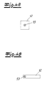
- the excitation surface 12 in the focus area is in Fig. 4A extended over 10 x 10 mm.
- the measuring surface 13 of about 2 x 2 mm is clearly outshined, causing blurring of the measuring head 3 along the Sample surface can be well balanced.
- a homogeneous intensity distribution over the excitation surface which in the exemplary embodiment has a fluctuation ratio (extrema to the mean) of at most 20%.
- the excitation light sources 4 and the optics relating to the excitation light are dimensioned or aligned in such a way that the excitation surface 12 is elongate and the photothermal measuring device is correspondingly well suited for relatively high machine-related relative velocities.
- the excitation surface 12 of this variant has an area of 3 ⁇ 20 mm.
- the measuring surface 13, however, is extended over 2 x 2 mm.
- the user guides the measuring head 3 to the sample 5.
- the Rayleigh length is quite large with +/- 5 mm, so that the distance finding is not a problem for the user.
- the user triggers, for example by means of a button in the region of the handle, the photothermal measurement, whereby the excitation light sources 4 a light pulse with a u. a. emit a sample-dependent duration of 0.1 to 3 seconds. Due to the light pulse, the sample 5 heats up, which results in radiation of heat radiation.
- the infrared sensor 6 determines u.a. the rise and the decay of the collected over the infrared lens 10 thermal radiation.
- An intensity profile of the thermal radiation over time obtained in this way is digitized in a further step.
- the digitized intensity values of the heat radiation are then transmitted to the arithmetic unit, where the layer thicknesses of the sample 5 are calculated.
- the measured intensity profile is compared there with the characteristic behavior of the expected material by the arithmetic unit.
- the layer thickness can then be derived via such a reference adjustment.
Landscapes
- Physics & Mathematics (AREA)
- General Physics & Mathematics (AREA)
- Investigating Or Analyzing Materials Using Thermal Means (AREA)
Abstract
Description
- Die Erfindung betrifft ein fotothermisches Messgerät zur Messung von Schichtdicken, insbesondere von Lackschichtdicken. Weiterhin betrifft die Erfindung ein Verfahren zur fotothermischen Messung mit einem fotothermischen Messgerät.
- Bekanntermaßen wird bei fotothermischen Messungen ein Anregungslichtpuls mithilfe eines Messkopfes auf eine Probe geworfen. Aufgrund der hohen Energiedichte des Anregungslichtpulses erwärmt sich die Probe, wodurch Wärmestrahlung von der Probe zurückgeworfen und mittels des Messkopfes aufgefangen werden kann. Anhand des ermittelten Intensitätsverlaufes der Wärmestrahlung können dann die Schichtdicken der Probe berechnet werden. Die in der Praxis bekannten fotothermischen Messgeräte weisen dabei entweder fest angeordnete Messköpfe auf oder aber sie verfügen über maschinell verfahrbare Messköpfe. Mit der Hand führbare Messköpfe zwecks Ermöglichung manuell durchgeführter Messungen sind ebenfalls bekannt, doch muss hierzu die führende Hand abgestützt werden. Folglich handelt es sich bei diesen Messungen zwar um handgeführte Messungen, nicht aber um echte Freihandmessungen, bei denen die führende Hand bzw. der führende Arm nicht abgestützt werden muss.
- Größtes Hindernis von Freihandmessungen - ohne Einschränkungen aufgrund von Schutznormen hinnehmen zu müssen - ist dabei die Messzeit bis zu einigen wenigen Sekunden. Selbst wenn der Nutzer in dieser Zeit sich auf eine ruhig gehaltene Hand konzentriert, erfährt der Messkopf dennoch verschiedenste Bewegungskomponenten in alle Raumrichtungen, welche zwar kaum sichtbar sind, aber dennoch häufig zur völligen Unbrauchbarkeit der jeweiligen Messung führen. Diese Bewegungskomponenten in alle Raumrichtungen sind auch als Verwackeln bekannt. Hier ist zu unterscheiden zwischen einer Bewegungskomponente entlang der Strahlachse einerseits und zwischen Bewegungskomponenten parallel zur Oberfläche der Probe andererseits. Insbesondere die letztgenannten Bewegungskomponenten können zu erheblichen Messwertstreuungen führen. In der Praxis bedeutet dies, dass eine Vielzahl von Messwerten aufgenommen werden muss, um die große Varianz der Messwerte zu kompensieren. Werden lediglich einige wenige Messungen aufgenommen, so ist das Ergebnis mit einiger Unsicherheit behaftet.
- Der Erfindung liegt daher das technische Problem zugrunde, beispielsweise für eine fertigungsnahe Qualitätskontrolle von Lackschichten, ein fotothermisches Messgerät anzugeben, bei welchem die Zuverlässigkeit der Messungen erhöht wird. Vorzugsweise ist es Aufgabe, die Zuverlässigkeit soweit zu erhöhen, dass auch fotothermische Messungen mit freihändig geführten Messköpfen ermöglicht werden. Weiterhin liegt der Erfindung das technische Problem zugrunde, ein Verfahren zur fotothermischen Messung anzugeben, welches die Zuverlässigkeit der fotothermischen Messung erhöht und insbesondere auch fotothermische Messgeräte mit freihändig geführten Messköpfen erlaubt.
- Zur Lösung des technischen Problems lehrt die Erfindung ein fotothermisches Messgerät, umfassend wenigstens eine Anregungslichtquelle zur Erwärmung einer Probe, einen Infrarot-Detektor zur Detektion von Wärmestrahlung der erwärmten Probe und einen Messkopf, wobei der Messkopf ein Linsensystem zur Bündelung des Anregungslichtes auf der Probe sowie zur Sammlung der von der Probe ausgehenden Wärmestrahlung aufweist, wobei das Linsensystem einen Fokus des Anregungslichtes bestimmt, wobei das Linsensystem und der Infrarot-Detektor eine Messfläche definieren und wobei eine Anregungsfläche 0,5 mm2 bis 1000 mm2, bevorzugt 2 mm2 bis 600 mm2 und besonders bevorzugt 8 mm2 bis 200 mm2 beträgt.
- Die Begrifflichkeit "Messkopf" meint den Teil des fotothermischen Messgerätes, welcher das Linsensystem umfasst. Der Messkopf kann separat ausgebildet sein, so dass er über ein Kabel mit einer Grundeinheit verbunden ist. Der Messkopf kann aber auch in der Grundeinheit verbaut sein bzw. kann die Grundeinheit selber sein, so dass der Messkopf allenfalls am Linsensystem erkennbar ist. Vorteilhafterweise weist die Grundeinheit einen Griff und besonders vorzugsweise einen Akku auf. In Verbindung mit der Möglichkeit der reinen Freihandmessung wird so ein vollumfänglich mobiles fotothermisches Messgerät geschaffen.
- Der Begriff "Anregungsfläche" meint die Querschnittsfläche des Anregungslichtes im Fokus. Als Rand der Anregungsfläche sind diejenigen Stellen definiert, bei welchen die maximale Intensität des Anregungslichtstrahls auf den Wert 1/e2 und somit auf etwa 13 % des Hauptmaximums der Anregungsfläche gesunken ist. Die Anregungsfläche meint insbesondere eine zusammenhängende Fläche und damit nicht eine Vielzahl von Flächen. Vorzugsweise ist die Anregungsfläche durchgehend und weist somit keine Einschlüsse mit Bereichen von weniger als 13 % Intensität bezüglich des Hauptmaximums auf.
- Das Wort "Messfläche" ist anders als die Anregungsfläche definiert. Die Messfläche wird durch die aktive Oberfläche des Infrarot-Detektors sowie durch den Abbildungsmaßstab bestimmt. Der Abbildungsmaßstab wiederum wird durch die einsammelnde Optik des Linsensystems sowie durch die Position des Infrarot-Detektors zur einsammelnden Optik über die Linsengleichung definiert. Die Messfläche liegt bevorzugt in der Ebene der Anregungsfläche und wird besonders bevorzugt von der Anregungsfläche umschlossen.
- Der Erfindung liegt die Erkenntnis zugrunde, dass die Ursache für die bisherige Unbrauchbarkeit der Messungen von handgeführten Messköpfen zu einem großen Teil in dem natürlichen Verwackeln mit der Hand begründet ist. Dies ist grob vergleichbar mit verwackelten fotografischen Aufnahmen bei zu großen Belichtungszeiten. Bisher wurde als Anregungslicht zwecks Erreichung einer größeren Leistungsdichte und damit tendenziell zuverlässigeren Messungen verhältnismäßig stark auf eine kleinere Anregungsfläche im µm2-Bereich gebündelt. Diese kleinere Anregungsfläche in Verbindung mit dem Verwackeln erzeugt jedoch eine örtlich sehr inhomogene Anregung der Probenoberfläche. Gleichzeitig führt das Verwackeln auch dazu, dass die Messfläche in mehr oder weniger willkürlicher Art und Weise über die inhomogen angeregten Probenoberflächen hinweg gleitet. In der Folge wird die freihändige fotothermische Messung unzuverlässig. Dieses Problem wird dadurch behoben, dass die Anregungsfläche 0,5 mm2 bis 1000 mm2, vorzugsweise 2 mm2 bis 600 mm2 und besonders bevorzugt 8 mm2 bis 200 mm2 beträgt. Gemäß anderen Ausführungsformen beträgt die Anregungsfläche 1 mm2 bis 800 mm2, 5 mm2 bis 400 mm2 oder auch 20 mm2 bis 150 mm2. Besonders bevorzugt ist eine Anregungsfläche zwischen 40 mm2 und 120 mm2. Die bevorzugtesten Ausführungsformen weisen eine Anregungsfläche zwischen 60 mm2 und 100 mm2 auf. Dies widerspricht dem in der Fotothermik bisher üblichen Grundsatz, kleine Anregungsflächen zu verwenden, deutlich. Insofern stellt die Erfindung eine Abkehr von bisherigen Grundsätzen dar. Insbesondere wurde überraschend gefunden, dass die Vorteile einer großflächigen, aber entsprechend intensitätsarmen Anregung diejenigen Vorteile einer intensitätsreichen, aber kleinflächigen Anregung im Falle von Freihandmessungen überwiegen.
- Es liegt im Rahmen der Erfindung, dass die Anregungsfläche etwa kreisförmig oder etwa quadratisch ist. Gemäß einer anderen Ausführungsform ist die Anregungsfläche länglich ausgebildet und weist ein Breiten-zu-Längen-Verhältnis auf, welches kleiner als 1:2, vorzugsweise kleiner als 1:4 und besonders vorzugsweise kleiner als 1:6 ist. Dem liegt die Erkenntnis zugrunde, dass eine länglich ausgebildete Anregungsfläche sich sehr gut für gleichmäßige, aber hohe Relativgeschwindigkeiten eignet. Hiermit sind Vorrichtungen gemeint, bei welchen in der Regel die Probe zum Messkopf verfahren wird. Ferner sind auch Vorrichtungen gemeint, bei denen der Messkopf selber über die Probe verfahren wird. Vorzugsweise ist die Messfläche innerhalb eines ersten Endes der länglich ausgebildeten Anregungsfläche angeordnet, so dass die Anregungsfläche der Messfläche in Verfahrrichtung vorauseilt. Hierdurch wird bewirkt, dass ein Teil der zu vermessenden Strecke im Vorfeld angeregt wird, so dass sowohl eine homogene als auch eine hohe Anregung entlang der Messtrecke erreicht werden. Auf diese Art und Weise können Relativgeschwindigkeiten von 1 bis 200 m/min erzielt werden.
- Vorteilhafterweise weichen die Extrema der Intensität der Anregungsfläche höchstens um 50 %, vorzugsweise höchstens um 20 % und besonders vorzugsweise höchstens um 10% vom Intensitätsmittelwert der Anregungsfläche ab. Extrema im Sinne der Erfindung sind Maxima und Minima im mathematischen Sinne. Allerdings werden die Extrema am Rand der Anregungsfläche nicht zur Berechnung des obigen Verhältnisses herangezogen. Gemäß einer bevorzugten Ausführungsform ist ein Intensitätsgradient am Rande der Anregungsfläche geringer als 20%, vorzugsweise geringer als 10%, besonders vorzugsweise geringer als 5% und idealerweise geringer als 2%. Der Begriff "Intensitätsgradient" meint, dass die Anregungsfläche in 10 x 10 gleichgroße Flächenstücke aufgeteilt wird, wobei der Intensitätsmittelwert jedes einzelnen der 36 äußeren Flächenstücke um nicht mehr als 20% bzw. 10% bzw. 5% bzw. 2% von dem Intensitätsmittelwert jedes anderen der 36 Flächenstücke abweicht. Den angegebenen Verhältnissen liegt die Erkenntnis zugrunde, dass Schwankungen innerhalb der genannten Verhältnisse für die Zuverlässigkeit noch tolerabel bzw. vorteilhaft oder sehr vorteilhaft sind.
- Es liegt im Rahmen der Erfindung, dass die wenigstens eine Anregungslichtquelle eine Leuchtiode und vorzugsweise eine Nahinfrarot- oder UV-Leuchtiode ist. Zweckmäßigerweise ist die Leuchtdiode ein Kantenemitter. Bevorzugt ist die Anregungslichtquelle inkohärent, ist also kein Laser. Dem liegt die Erkenntnis zugrunde, dass Leuchtioden in Form von Kantenemittern verhältnismäßig große Kantenlängen aufweisen (Millimeter statt Mikrometer wie bei Laserioden), so dass die Abbildungen dieser aktiv leuchtenden Flächen im Fokus dementsprechend groß sind, was wiederum zu einer entsprechend großen Anregungsfläche führt. Ferner führt eine große Abbildung im Fokus außerdem auch zu einer großen Rayleighlänge, wodurch die Schwankungsunempfindlichkeit in Strahlrichtung vergrößert wird. Folglich ist die Wahl von Leuchtioden in Form von Kantenemitten besonders vorteilhaft, weil sie sowohl die Schwankungsunempfindlichkeit in Strahlrichtung als auch die Schwankungsunempfindlichkeit entlang der Probenoberfläche vergrößern. Vorzugsweise beträgt die Rayleighlänge des Anregungslichtes 1 mm bis 20 mm und weiter vorzugsweise 1 mm bis 10 mm.
- Gemäß einer bevorzugten Ausführungsform beträgt die Messfläche 0,2 bis 50 mm2, vorzugsweise 0,5 bis 20 mm2 und besonders vorzugsweise 1 bis 10 mm2. Diesem Aspekt liegt die Erkenntnis zugrunde, dass die Wahl der Messfläche einen Kompromiss darstellt. Ist die Messfläche zu klein gewählt, so spielen Unregelmäßigkeiten von Schichtdicken eine immer größere Rolle, was dazu führen kann, dass bereits eine sehr kleine Verschiebung der Messfläche auf der Probe aufgrund einer Änderung der Schichtdicke zu unterschiedlichen Ergebnissen führt. Dies hat eine erhöhte Unzuverlässigkeit zur Folge. Ist die Messfläche hingegen im erfindungsgemäßen Bereich, so wird die Schichtdicke über diesen Bereich gemittelt, was einen deutlich aussagekräftigeren, weil stabileren Wert ergibt. Wird die Messfläche noch größer, so wird die Ortsauflösung jedoch zu ungenau.
- Es ist vorteilhaft, dass die Anregungsfläche wenigstens um den Faktor 2, vorzugsweise um den Faktor 5 und besonders vorzugsweise um den Faktor 10 größer ist als die Messfläche. Der Wahl dieses Verhältnisses liegt die Erkenntnis zugrunde, dass hierdurch besonders zuverlässige Messergebnisse erreicht werden.
- Gemäß einer besonders bevorzugten Ausführungsform ist der Messkopf zur Führung mit der Hand geeignet. Der Ausdruck "zur Führung mit der Hand geeignet" bedeutet, dass der Messkopf von Größe und Gewicht nicht nur von der Hand gehalten werden kann, sondern zugleich auch einige wenige Sekunden ruhig gegenüber einer Probe gehalten werden kann. Folglich scheiden Messköpfe aus, welche zwar einen Griff aufweisen, aber beispielsweise zu schwer sind, um ruhig vor einer Probe gehalten werden zu können. Ebenso scheiden Messköpfe aus, welche zwar sehr leicht, dafür aber sehr voluminös sind. Vielmehr kommen als Messköpfe Gegenstände in Betracht, welche von Größe und Gewicht beispielsweise einen Stift, einer Maus, einer Pistole oder einer Taschenlampe entsprechen.
- Es liegt im Rahmen der Erfindung, dass das fotothermische Messgerät eine Mehrzahl von Anregungslichtquellen und bevorzugt wenigstens zwei, weiter bevorzugt wenigstens drei und ganz besonders bevorzugt wenigstens fünf Anregungslichtquellen aufweist. Gemäß einer speziellen Ausführungsform weist das fotothermische Messgerät sechs Anregungslichtquellen auf. Dem liegt die Erkenntnis zugrunde, dass mit mehreren Anregungslichtquellen einerseits mehr optische Leistung erzeugt werden kann und andererseits die optische Leistung noch etwas gleichmäßiger verteilt werden kann.
- Es ist vorteilhaft, dass die Leistungsdichte des Anregungslichtes in der Anregungsfläche zwischen 1 und 100 mW/mm2 und bevorzugt zwischen 10 und 100mW/mm2 beträgt. Diesem Aspekt liegt die Erkenntnis zugrunde, dass hierdurch besonders zuverlässige Ergebnisse gewährleistet werden. Es ist zweckmäßig, dass die Messzeit einer fotothermischen Messung 0,02 bis 10 s, vorzugsweise 0,05 bis 5 s und besonders vorzugsweise 0,1 bis 3 s entspricht.
- Wenn der Fokus des Anregungslichtes 5 bis 150 mm, bevorzugt 10 bis 80 mm und besonders bevorzugt 25 bis 40 mm von dem Linsensystem beabstandet ist, wird insbesondere dem Nutzungsverhalten bei der Führung mit der menschlichen Hand Rechnung getragen. So wurde gefunden, dass zu große Abstände für den Nutzer schwierig einzuschätzen sind; hingegen bedingen zu kurze Abstände die Gefahr der versehentlichen Berührung.
- Gemäß einer besonders bevorzugten Ausführungsform umfasst das fotothermische Messgerät ein Abstandsmessgerät. Das Abstandsmessgerät ist vorzugsweise in der Lage, automatisch Abstandsmessungen zwischen dem Messkopf und der Probe vorzunehmen. Es ist bevorzugt, dass das Abstandsmessgerät eine Vielzahl von Abständen messen kann. Vorzugsweise ist das Abstandsmessgerät für eine beliebige Methode zur berührungsfreien Abstandsmessung ausgelegt. Gemäß bevorzugten Ausführungsformen werden die Abstände mittels Auswertungen von Wellen, beispielsweise Schall-, Funk- und Lichtwellen, erfasst. Vorzugsweise arbeitet das Abstandsmessgerät nach einem optischen Verfahren, also mit Lichtwellen. Weiter vorzugsweise ermittelt das Abstandsmessgerät nach einem der optischen Verfahren der Triangulation, der Laufzeitmessung oder der Phasenverschiebungsmessung die Abstände. Dabei ist das Verfahren der optischen Triangulation bevorzugt. Besonders vorteilhafterweise wird das Licht des Abstandsmessgerätes über das Linsensystem auf die Probe geworfen und von dort wieder über das Linsensystem eingefangen. Diesem Aspekt liegt die Erkenntnis zugrunde, dass mithilfe eines Abstandsmessgerätes automatische Abstandsmessungen möglich sind, wodurch die fotothermische Messung zum richtigen Zeitpunkt ausgelöst wird. Dadurch wird die Schwankungsunempfindlichkeit in Strahlrichtung verringert. Außerdem kann mithilfe des Abstandsmessgerätes ein Schwankungsprofil in Strahlrichtung erstellt werden, mit dessen Hilfe das gemessene Intensitätsprofil korrigiert werden kann. Hierdurch kann die Schwankungsunempfindlichkeit in Strahlrichtung auf ein Mindestmaß verringert werden.
- Vorteilhafterweise ist der optische Pfad des Anregungslichtes von dem optischen Pfad der Wärmestrahlung entkoppelt. Dabei bedeutet der Begriff "entkoppelt", dass einige Optiken hauptsächlich vom Anregungslicht, und andere Optiken hauptsächlich von der Wärmestrahlung durchlaufen werden. Dies erlaubt die Optimierung der Optiken auf das jeweilige Licht hinsichtlich der Wellenlänge.
- Gemäß einer besonders bevorzugten Ausführungsform weist das Linsensystem eine Ringlinse auf, welche eine erste Strahlachse definiert. Es ist zweckmäßig, dass das Linsensystem eine Infrarot-Linse umfasst. Vorteilhafterweise ist die Infrarot-Linse mit einer zweiten Strahlachse im Ringloch der Ringlinse angeordnet. Bevorzugt liegt die zweite Strahlachse auf der ersten Strahlachse. Vorteilhafterweise definiert die Infrarot-Linse zusammen mit dem Infrarot-Detektor die Messfläche. Ganz besonders bevorzugt fokussiert die Ringlinse das Anregungslicht. Es ist zweckmäßig, dass die Ringlinse die Anregungslichtstrahlen einander im Fokus überlagert. Weiterhin ist es vorteilhaft, dass die Ringlinse sphärisch ist. Dem Aspekt der Ringlinse liegen verschiedene Erkenntnisse zugrunde. So ermöglicht die Ringlinse, dass die Infrarot-Linse im Ringloch ein Maximum an Wärmestrahlung einsammeln kann, wodurch die Zuverlässigkeit der Messung bzw. die Messgeschwindigkeit erhöht wird. Ferner erlaubt die Ringlinse eine konzentrische Anordnung der Anregungslichtquellen um die Strahlachse herum, wodurch eine verhältnismäßig homogene Ausleuchtung der Anregungsfläche erzielt wird. Das Übereinanderliegen der Fokusse resultiert in einer besonders schwankungsunempfindlichen Messung in Strahlrichtung. Ist die Ringlinse sphärisch, so vergrößert sich die Aberration im Fokus, wodurch die Rayleighlänge und damit die Schwankungsunempfindlichkeit in Strahlrichtung vergrößert wird.
- Gemäß einer bevorzugten Ausführungsform umfasst das fotothermische Messgerät wenigstens eine, vorzugsweise zwei und besonders vorzugsweise drei Pilotlichtquellen. Bevorzugt zeigt bzw. zeigen die Pilotlichtquellen auf den Ort der fotothermischen Messung auf der Probe. Weiter bevorzugt zeigen die Pilotlichtquellen den Messabstand an, indem die Strahlen der Pilotlichtquellen einander im Fokus schneiden. Die Pilotlichtquellen sind vorteilhafterweise Leuchtdioden, welche zweckmäßigerweise eine Wellenlänge im sichtbaren roten Spektrum aufweisen. Ganz besonders bevorzugt werden auch die Lichtstrahlen der Pilotlichtquellen durch das Linsensystem und insbesondere durch die Ringlinse fokussiert und treffen im Fokus des Linsensystems bzw. der Ringlinse aufeinander. Diesem Aspekt liegt die Erkenntnis zugrunde, dass hierdurch eine für den Nutzer sichtbare Positionsanzeige für den korrekten Messabstand ermöglicht wird. Dabei erlaubt eine Pilotlichtquelle zumindest die Anzeige der Strahlrichtung, wohingegen zwei einander schneidende Pilotlichtstrahlen bereits einen bestimmten Ort im dreidimensionalen Raum und damit beispielsweise auch den Fokus der Ringlinse bzw. des Linsensystems anzeigen können. Der dritte Pilotlichtstrahl schließlich ermöglicht eine bessere Sichtbarkeit des Schnittpunktes.
- Zweckmäßigerweise weist der optische Pfad des Anregungslichtes wenigstens einen Kollimator und bevorzugt für jede Anregungslichtquelle einen zugehörigen Kollimator auf. Dem liegt die Erkenntnis zugrunde, dass hierdurch das Linsensystem flexibler ist und somit die Lichtstrahlen bedarfsgerechter geformt werden können. Es ist vorteilhaft, wenn der optische Pfad des Anregungslichtes wenigstens einen Diffusor und bevorzugt für jede Anregungslichtquelle einen Diffusor aufweist. Besonders bevorzugt ist ein holografischer Diffusor. Dem liegt die Erkenntnis zugrunde, dass die Anregungslichtstrahlen hierdurch gestreut werden, wodurch wiederum die Anregungsfläche und die Rayleighlänge vergrößert werden.
- Die Erfindung lehrt zur Lösung des technischen Problems ein Verfahren zur fotothermischen Messung mit einem insbesondere erfindungsgemäßen fotothermischen Messgerät, wobei das fotothermische Messgerät einen Messkopf, wenigstens eine Anregungslichtquelle und einen Infrarot-Detektor umfasst, wobei der Messkopf ein Linsensystem aufweist, wobei das Linsensystem einen Fokus des Anregungslichtes bestimmt, wobei das Linsensystem das Anregungslicht auf die Probe bündelt, wobei sich die Probe aufgrund des Anregungslichtes erwärmt, wobei das Linsensystem die von der Probe ausgehende Wärmestrahlung einsammelt, wobei der Infrarot-Detektor die eingesammelte Wärmestrahlung detektiert, wobei das Linsensystem und der Infrarot-Detektor eine Messfläche definieren, wobei die detektierte Wärmestrahlung in Schichtdicke umgerechnet wird, und wobei die Querschnittsfläche des Anregungslichtes im Fokus des Anregungslichtes (Anregungsfläche) 0,5 mm2 bis 1000 mm2, bevorzugt 2 mm2 bis 600 mm2 und besonders bevorzugt 8 mm2 bis 200 mm2 beträgt.
- Nachfolgend wird die Erfindung anhand einer ein Ausführungsbeispiel darstellenden Zeichnung näher erläutert. Es zeigen in schematischer Darstellung:
- Fig.1
- eine perspektivische Ansicht eines erfindungsgemäßen fotothermischen Messgerätes bei der Anwendung.
- Fig. 2
- einen Längsschnitt durch einen Messkopf des fotothermischen Messgerätes aus
Fig. 1 , - Fig. 3
- eine Vorderansicht des Messkopfes aus den
Fig. 1 und2 , - Fig. 4A
- eine erste Variante einer Anregungsfläche des Messkopfes der
Fig. 1 bis 3 , - Fig. 4B
- eine weitere Variante der Anregungsfläche des Messkopfes aus den
Fig. 1 bis 3 . -
Fig. 1 zeigt das erfindungsgemäße fotothermische Messgerät in einer vereinfachenden Darstellung. Das fotothermische Messgerät umfasst eine Grundeinheit 1, ein Kabel 2 sowie einen mit der Hand führbaren Messkopf 3. Dabei werden die Grundeinheit 1 und der Messkopf 3 mit dem Kabel 2 miteinander verbunden. Im vorliegenden Ausführungsbeispiel umfasst die Grundeinheit eine nicht dargestellte Spannungsversorgung sowie eine nicht dargestellte Recheneinheit. Ferner sind an der Grundeinheit 1 nicht dargestellte Schnittstellen vorgesehen, mit welchen die Grundeinheit 1 an Rechner bzw. Ein- und Ausgabegeräte angeschlossen werden kann. Der Messkopf 3 weist einen ergonomischen Griff auf, an welchem einends das Kabel 2 befestigt ist und an welchem anderenends die für die fotothermische Messung maßgeblichen optischen Komponenten angeordnet sind. Aufgrund der Abmessungen und des Gewichts des Messkopfes 3 ist das fotothermische Messgerät besonders gut zur manuellen Messung geeignet. Ein typischer Anwendungsfall ist die fertigungsnahe Qualitätsüberprüfung von Lackpulverschichten auf Metall vor dem Einbrennvorgang. Eine solche mehrschichtige Probe ist mit dem Bezugszeichen 5 angedeutet. - Der Längsschnitt in
Fig. 2 verdeutlicht die Strahlengänge zwischen Messkopf 3 und Probe 5 und ist in Verbindung mit der Vorderansicht des Messkopfes 3 ausFig. 3 zu sehen. Die von der Spannungsversorgung über das Kabel 2 an eine Platine 11 herangeführte elektrische Leistung wird über die Platine 11 weiter an insgesamt sechs Anregungslichtquellen 4 sowie an einen Infrarot-Detektor 6 verteilt. Im Falle der Anregungslichtquellen handelt es sich um Nahinfrarot-Leuchtdioden mit einer Kantenlänge im Millimeter-Bereich. Das divergent aus den Anregungslichtquellen 4 austretende Anregungslicht trifft zunächst auf einen der jeweiligen Anregungslichtquelle 4 zugeordneten Kollimator 7, wodurch die divergenten Anregungslichtstrahlen kollimiert werden. Durch eine Ringlinse 8 werden die kollimierten Anregungslichtstrahlen auf die Probe 5 in einem Fokuspunkt F fokussiert. Dabei wird nicht nur der jeweilige Anregungslichtstrahl der sechs Anregungslichtquellen 4 gebündelt, sondern darüber hinaus werden auch noch die sechs Anregungslichtstrahlen im Fokus F einander überlagert. Im Fokus F erwärmt sich die Probe 5, so dass sie Wärmestrahlung emittiert. Diese Wärmestrahlung wird mittels einer Infrarot-Linse 10 eingesammelt und auf den Infrarot-Detektor 6 fokussiert. Zusammen mit den Kollimatoren 7 und der Ringlinse 8 bildet die Infrarot-Linse 10 ein Linsensystem 9. - Aufgrund einer Rayleighlänge von +/- 5 mm um den Fokus F herum ist auch der zugehörige nutzbare Messabstandsbereich entsprechend groß und die Messung bezüglich Positionierung des Messkopfes 3 in Strahlrichtung dementsprechend tolerant. Die Anregungsfläche 12 im Fokusbereich ist in
Fig. 4A über 10 x 10 mm ausgedehnt. Damit wird die Messfläche 13 von etwa 2 x 2 mm deutlich überstrahlt, wodurch Verwacklungen des Messkopfes 3 entlang der Probenoberfläche gut ausgeglichen werden können. Wichtig hierfür ist auch eine homogene Intensitätsverteilung über der Anregungsfläche, welche in dem Ausführungsbeispiel ein Schwankungsverhältnis (Extrema zum Mittelwert) von höchstens 20 % aufweist. In einer inFig. 4B dargestellten zweiten Variante sind die Anregungslichtquellen 4 und die das Anregungslicht betreffenden Optiken so dimensioniert bzw. ausgerichtet, dass die Anregungsfläche 12 länglich ausgebildet ist und das fotothermische Messgerät entsprechend gut für hohe maschinell bedingte Relativgeschwindigkeiten geeignet ist. Die Anregungsfläche 12 dieser Variante weist eine Fläche von 3 x 20 mm auf. Die Messfläche 13 hingegen ist über 2 x 2 mm ausgedehnt. - Zwecks manueller Messung der Schichtdicke an der Probe 5 führt der Anwender den Messkopf 3 an die Probe 5 heran. Wie oben beschrieben, ist die Rayleighlänge mit +/- 5 mm recht groß, so dass die Abstandsfindung für den Anwender kein Problem darstellt. Daraufhin löst der Anwender, beispielsweise mittels eines Knopfes im Bereich des Griffes, die fotothermische Messung aus, wodurch die Anregungslichtquellen 4 einen Lichtpuls mit einer u. a. probenabhängigen Dauer von 0,1 bis 3 Sekunden emittieren. Aufgrund des Lichtpulses erwärmt sich die Probe 5, was eine Abstrahlung von Wärmestrahlung zur Folge hat. Der Infrarot-Sensor 6 ermittelt u.a. den Anstieg und das Abklingen der über die Infrarot-Linse 10 eingesammelten Wärmestrahlung. Ein solcherart gewonnenes Intensitätsprofil der Wärmestrahlung über der Zeit wird in einem weiteren Schritt digitalisiert. In einem letzten Schritt werden dann die digitalisierten Intensitätswerte der Wärmestrahlung zu der Recheneinheit übertragen, wo die Schichtdicken der Probe 5 berechnet werden. Der gemessene Intensitätsverlauf wird dort mit dem charakteristischen Verhalten des erwarteten Materials durch die Recheneinheit verglichen. Über einen derartigen Referenzabgleich kann dann die Schichtdicke abgeleitet werden.
Claims (15)
- Fotothermisches Messgerät, umfassend
wenigstens eine Anregungslichtquelle (4) zur Erwärmung einer Probe (5), einen Infrarot-Detektor (6) zur Detektion von Wärmestrahlung der erwärmten Probe (5) und einen Messkopf (3),
wobei der Messkopf (3) ein Linsensystem (9) zur Bündelung des Anregungslichtes auf der Probe (5) sowie zur Sammlung der von der Probe (5) ausgehenden Wärmestrahlung aufweist,
wobei das Linsensystem (9) einen Fokus (F) des Anregungslichtes bestimmt, wobei das Linsensystem (9) und der Infrarot-Detektor (6) eine Messfläche (13) definieren
und wobei eine Anregungsfläche (12) 0,5 mm2 bis 1000 mm2, bevorzugt 2 mm2 bis 600 mm2 und besonders bevorzugt 8 mm2 bis 200 mm2 beträgt. - Fotothermisches Messgerät nach Anspruch 1, wobei die Extrema der Intensität der Anregungsfläche (12) höchstens um 50 %, vorzugsweise höchstens um 20 % und besonders vorzugsweise höchstens um 10 % vom Intensitätsmittelwert der Anregungsfläche (12) abweichen.
- Fotothermisches Messgerät nach Anspruch 1 oder 2, ein Intensitätsgradient am Rande der Anregungsfläche (12) geringer als 20%, vorzugsweise geringer als 10% und besonders vorzugsweise geringer als 5% ist.
- Fotothermisches Messgerät nach einem der Ansprüche 1 bis 3, wobei die wenigstens eine Lichtquelle (4) eine Leuchtiode und vorzugsweise eine Nahinfrarot- oder UV-Leuchtiode ist.
- Fotothermisches Messgerät nach einem der Ansprüche 1 bis 4, wobei die Messfläche (13) 0,2 bis 50 mm2, vorzugsweise 0,5 bis 20 mm2 und besonders vorzugsweise 1 bis 10 mm2 groß ist.
- Fotothermisches Messgerät nach einem der Ansprüche 1 bis 5, wobei die Anregungsfläche (13) wenigstens um den Faktor 2, vorzugsweise um den Faktor 5 und besonders vorzugsweise um den Faktor 10 größer ist als die Messfläche (13).
- Fotothermisches Messgerät nach einem der Ansprüche 1 bis 6, wobei der Messkopf (3) zur Führung mit der Hand geeignet ist.
- Fotothermisches Messgerät nach einem der Ansprüche 1 bis 7, wobei das fotothermische Messgerät eine Mehrzahl von Anregungslichtquellen (4) aufweist.
- Fotothermisches Messgerät nach einem der Ansprüche 1 bis 8, wobei die Intensität des Anregungslichtes in der Anregungsfläche (12) zwischen 1 mW/mm2 und 100mW/mm2 und bevorzugt zwischen 10 mW/mm2 und 100 mW/mm2 liegt.
- Fotothermisches Messgerät nach einem der Ansprüche 1 bis 9, wobei das fotothermische Messgerät ein Abstandsmessgerät umfasst.
- Fotothermisches Messgerät nach einem der Ansprüche 1 bis 10, wobei der optische Pfad des Anregungslichtes von dem optischen Pfad der Wärmestrahlung entkoppelt ist.
- Fotothermisches Messgerät nach einem der Ansprüche 1 bis 11, wobei das Linsensystem (9) eine Ringlinse (8) aufweist, welche eine erste Strahlachse definiert.
- Fotothermisches Messgerät nach einem der Ansprüche 1 bis 12, wobei das fotothermische Messgerät wenigstens eine, vorzugsweise zwei und besonders vorzugsweise drei Pilotlichtquellen umfasst.
- Fotothermisches Messgerät nach einem der Ansprüche 1 bis 13, wobei das Linsensystem (9) wenigstens einen Kollimator (7) aufweist.
- Verfahren zur fotothermischen Messung, mit einem fotothermischen Messgerät insbesondere gemäß einem der Ansprüche 1 bis 14, wobei das fotothermische Messgerät einen Messkopf (3), wenigstens eine Anregungslichtquelle (4) und einen Infrarot-Detektor (6) umfasst,
wobei der Messkopf (3) ein Linsensystem (9) aufweist,
wobei das Linsensystem (9) einen Fokus (F) des Anregungslichtes bestimmt, wobei das Linsensystem (9) und der Infrarot-Detektor (6) eine Messfläche (13) definieren,
wobei die wenigstens eine Anregungslichtquelle (4) Anregungslicht ausstrahlt, wobei das Linsensystem (9) das Anregungslicht auf die Probe (5) bündelt, wobei sich die Probe (5) aufgrund des Anregungslichtes erwärmt,
wobei das Linsensystem (9) die von der Probe (5) ausgehende Wärmestrahlung einsammelt, wobei der Infrarot-Detektor (6) die eingesammelte Wärmestrahlung detektiert, wobei die detektierte Wärmestrahlung in eine Schichtdicke umgerechnet wird,
wobei eine Anregungsfläche (12) 0,5 mm2 bis 1000 mm2, bevorzugt 2 mm2 bis 600 mm2 und besonders bevorzugt 8 mm2 bis 200 mm2 beträgt.
Priority Applications (1)
| Application Number | Priority Date | Filing Date | Title |
|---|---|---|---|
| EP15164324.4A EP3086087B1 (de) | 2015-04-20 | 2015-04-20 | Fotothermisches messgerät sowie verfahren zur fotothermischen messung |
Applications Claiming Priority (1)
| Application Number | Priority Date | Filing Date | Title |
|---|---|---|---|
| EP15164324.4A EP3086087B1 (de) | 2015-04-20 | 2015-04-20 | Fotothermisches messgerät sowie verfahren zur fotothermischen messung |
Publications (2)
| Publication Number | Publication Date |
|---|---|
| EP3086087A1 true EP3086087A1 (de) | 2016-10-26 |
| EP3086087B1 EP3086087B1 (de) | 2021-07-07 |
Family
ID=53002531
Family Applications (1)
| Application Number | Title | Priority Date | Filing Date |
|---|---|---|---|
| EP15164324.4A Revoked EP3086087B1 (de) | 2015-04-20 | 2015-04-20 | Fotothermisches messgerät sowie verfahren zur fotothermischen messung |
Country Status (1)
| Country | Link |
|---|---|
| EP (1) | EP3086087B1 (de) |
Cited By (2)
| Publication number | Priority date | Publication date | Assignee | Title |
|---|---|---|---|---|
| WO2020169571A1 (de) * | 2019-02-20 | 2020-08-27 | Stefan Böttger | Verfahren und vorrichtung zur bestimmung einer schichtdicke einer auf ein substrat aufgebrachten schicht |
| DE102019004921B4 (de) * | 2019-02-20 | 2025-06-18 | Stefan Böttger | Verfahren und Vorrichtung zur Bestimmung einer Schichtdicke einer auf ein Substrat aufgebrachten Schicht |
Citations (5)
| Publication number | Priority date | Publication date | Assignee | Title |
|---|---|---|---|---|
| EP0609193A2 (de) * | 1993-01-26 | 1994-08-03 | HOERBIGER & Co. | Verfahren und Einrichtung zur Messung der Porosität von Reibbelägen |
| DE19520788A1 (de) * | 1995-01-13 | 1996-07-18 | Wissenschaftlich Tech Optikzen | Verfahren und Vorrichtung zur Bestimmung der Schichtdicke, der Leitfähigkeit und/oder der Schichtkontaktgüte von auf Substraten aufgetragenen Schichten |
| WO2001044752A1 (de) * | 1999-12-17 | 2001-06-21 | Abb Research Ltd. | Messvorrichtung |
| WO2011137547A2 (de) * | 2010-05-03 | 2011-11-10 | Winterthur Instruments Gmbh | Vorrichtung zur berührungslosen und zerstörungsfreien prüfung von oberflächen |
| FR3007831A1 (fr) * | 2013-07-01 | 2015-01-02 | Enovasense | Procede de mesure de l'epaisseur d'une couche d'un materiau, procede de galvanisation et dispositif de mesure associes |
Family Cites Families (5)
| Publication number | Priority date | Publication date | Assignee | Title |
|---|---|---|---|---|
| DE4343076C2 (de) | 1993-12-16 | 1997-04-03 | Phototherm Dr Petry Gmbh | Vorrichtung zum photothermischen Prüfen einer Oberfläche eines insbesondere bewegten Gegenstandes |
| DE19606453C2 (de) | 1996-02-21 | 1998-07-16 | Wagner Int | Verfahren und Vorrichtung zum photothermischen Prüfen von Werkstücken |
| DE19628391C1 (de) | 1996-07-13 | 1997-09-11 | Phototherm Dr Petry Gmbh | Signalverarbeitungseinheit einer Vorrichtung zum photothermischen Prüfen einer Oberfläche eines Prüfkörpers |
| DE19830473C1 (de) | 1998-07-08 | 1999-12-23 | Phototherm Dr Petry Gmbh | Vorrichtung zum Erzeugen und Erfassen von induzierter Wärmestrahlung |
| WO2011140664A2 (en) | 2010-05-13 | 2011-11-17 | Quantum Dental Technologies Inc. | Handpiece with integrated optical system for photothermal radiometry and luminescence measurements |
-
2015
- 2015-04-20 EP EP15164324.4A patent/EP3086087B1/de not_active Revoked
Patent Citations (5)
| Publication number | Priority date | Publication date | Assignee | Title |
|---|---|---|---|---|
| EP0609193A2 (de) * | 1993-01-26 | 1994-08-03 | HOERBIGER & Co. | Verfahren und Einrichtung zur Messung der Porosität von Reibbelägen |
| DE19520788A1 (de) * | 1995-01-13 | 1996-07-18 | Wissenschaftlich Tech Optikzen | Verfahren und Vorrichtung zur Bestimmung der Schichtdicke, der Leitfähigkeit und/oder der Schichtkontaktgüte von auf Substraten aufgetragenen Schichten |
| WO2001044752A1 (de) * | 1999-12-17 | 2001-06-21 | Abb Research Ltd. | Messvorrichtung |
| WO2011137547A2 (de) * | 2010-05-03 | 2011-11-10 | Winterthur Instruments Gmbh | Vorrichtung zur berührungslosen und zerstörungsfreien prüfung von oberflächen |
| FR3007831A1 (fr) * | 2013-07-01 | 2015-01-02 | Enovasense | Procede de mesure de l'epaisseur d'une couche d'un materiau, procede de galvanisation et dispositif de mesure associes |
Cited By (5)
| Publication number | Priority date | Publication date | Assignee | Title |
|---|---|---|---|---|
| WO2020169571A1 (de) * | 2019-02-20 | 2020-08-27 | Stefan Böttger | Verfahren und vorrichtung zur bestimmung einer schichtdicke einer auf ein substrat aufgebrachten schicht |
| CN113508276A (zh) * | 2019-02-20 | 2021-10-15 | 斯特凡·博特格 | 用于测定施覆至衬底的层的层厚的方法和装置 |
| DE102019004921B4 (de) * | 2019-02-20 | 2025-06-18 | Stefan Böttger | Verfahren und Vorrichtung zur Bestimmung einer Schichtdicke einer auf ein Substrat aufgebrachten Schicht |
| EP3928062B1 (de) | 2019-02-20 | 2025-06-18 | Stefan Böttger | Verfahren und vorrichtung zur bestimmung einer schichtdicke einer auf ein substrat aufgebrachten schicht |
| DE102019104260B4 (de) * | 2019-02-20 | 2025-09-11 | Stefan Böttger | Photothermisches Verfahren und Vorrichtung zur Bestimmung einer Schichtdicke einer auf ein Substrat aufgebrachten Schicht |
Also Published As
| Publication number | Publication date |
|---|---|
| EP3086087B1 (de) | 2021-07-07 |
Similar Documents
| Publication | Publication Date | Title |
|---|---|---|
| DE102011006553B4 (de) | Verfahren zum Ermitteln der Fokuslage eines Laserstrahls in seinem Arbeitsfeld oder Arbeitsraum | |
| DE102018105877B3 (de) | Vorrichtung für die Bestimmung einer Ausrichtung einer optischen Vorrichtung eines Kohärenztomographen, Kohärenztomograph und Laserbearbeitungssystem | |
| DE102008029459B4 (de) | Verfahren und Vorrichtung zur berührungslosen Abstandsmessung | |
| DE102019116309A1 (de) | Verfahren und Vorrichtung zur kontrollierten Bearbeitung eines Werkstücks | |
| DE102012212278B4 (de) | Anordnung zum Erzeugen von Bohrungen oder Schweißnähten | |
| EP2762832B1 (de) | Optische Einzelpunktmessung | |
| WO2014032773A1 (de) | System und verfahren zur optischen kohärenztomographie sowie positionierelement | |
| DE4109483A1 (de) | Verfahren und einrichtung zur detektion von kanten und bohrungen mit einem optischen tastkopf | |
| DE102017010055A1 (de) | Laserstrahlschweißen von geometrischen Figuren mit OCT-Nahtführung | |
| DE102017114033A1 (de) | Vorrichtung und Verfahren zur Abstandsmessung für ein Laserbearbeitungssystem, und Laserbearbeitungssystem | |
| EP0329986B1 (de) | Verfahren und Vorrichtung zur optischen Erfassung des Rauheitsprofils einer Materialoberfläche | |
| DE102022118147A1 (de) | Laserbearbeitungskopf und Verfahren zum Bearbeiten eines Werkstücks | |
| DE102022109740A1 (de) | Verfahren und Vorrichtung zur Durchführung optischer Kohärenzmessungen für eine Überwachung eines Bearbeitungsprozesses eines Werkstücks | |
| EP3086087B1 (de) | Fotothermisches messgerät sowie verfahren zur fotothermischen messung | |
| EP0791818B1 (de) | Verfahren und Vorrichtung zum photothermischen Prüfen von Werkstücken | |
| DE102018126846A1 (de) | Bearbeitungsvorrichtung zur Laserbearbeitung eines Werkstücks und Verfahren zur Laserbearbeitung eines Werkstücks | |
| DE2507040B2 (de) | Optoelektronische messvorrichtung fuer die lage einer kontrastierenden kante eines gegenstandes | |
| EP1642084A1 (de) | Visiereinrichtung und vorrichtung mit einer kontaktlos oder kontaktbehaftet einsetzbaren mess-, arbeits- und/oder wirkeinrichtung | |
| DE102014119436B4 (de) | Koordinatenmessgerät und Verfahren zum Bestimmen von geometrischen Eigenschaften eines Messobjekts unter Verwendung einer Lichtfeldkamera | |
| DE102014107142A1 (de) | Spaltvermessungsvorrichtung | |
| EP2975360B1 (de) | Photothermisches Messgerät zur Messung von Schichtdicken sowie Verfahren zur photothermischen Messung | |
| EP3374732B1 (de) | Verfahren und vorrichtung zur bestimmung der räumlichen position eines gegenstandes mittels interferometrischer längenmessung | |
| EP2606863B1 (de) | Vorrichtung und Verfahren zum Bestimmen der Fokusposition eines Laserstrahls | |
| DE3743194C2 (de) | ||
| DE102011053129B4 (de) | Musterprojektionsvorrichtung und Verfahren zur Abmessungsberechnung |
Legal Events
| Date | Code | Title | Description |
|---|---|---|---|
| PUAI | Public reference made under article 153(3) epc to a published international application that has entered the european phase |
Free format text: ORIGINAL CODE: 0009012 |
|
| AK | Designated contracting states |
Kind code of ref document: A1 Designated state(s): AL AT BE BG CH CY CZ DE DK EE ES FI FR GB GR HR HU IE IS IT LI LT LU LV MC MK MT NL NO PL PT RO RS SE SI SK SM TR |
|
| AX | Request for extension of the european patent |
Extension state: BA ME |
|
| 17P | Request for examination filed |
Effective date: 20161007 |
|
| RBV | Designated contracting states (corrected) |
Designated state(s): AL AT BE BG CH CY CZ DE DK EE ES FI FR GB GR HR HU IE IS IT LI LT LU LV MC MK MT NL NO PL PT RO RS SE SI SK SM TR |
|
| STAA | Information on the status of an ep patent application or granted ep patent |
Free format text: STATUS: EXAMINATION IS IN PROGRESS |
|
| 17Q | First examination report despatched |
Effective date: 20180820 |
|
| GRAP | Despatch of communication of intention to grant a patent |
Free format text: ORIGINAL CODE: EPIDOSNIGR1 |
|
| STAA | Information on the status of an ep patent application or granted ep patent |
Free format text: STATUS: GRANT OF PATENT IS INTENDED |
|
| INTG | Intention to grant announced |
Effective date: 20210211 |
|
| GRAS | Grant fee paid |
Free format text: ORIGINAL CODE: EPIDOSNIGR3 |
|
| GRAA | (expected) grant |
Free format text: ORIGINAL CODE: 0009210 |
|
| STAA | Information on the status of an ep patent application or granted ep patent |
Free format text: STATUS: THE PATENT HAS BEEN GRANTED |
|
| AK | Designated contracting states |
Kind code of ref document: B1 Designated state(s): AL AT BE BG CH CY CZ DE DK EE ES FI FR GB GR HR HU IE IS IT LI LT LU LV MC MK MT NL NO PL PT RO RS SE SI SK SM TR |
|
| REG | Reference to a national code |
Ref country code: GB Ref legal event code: FG4D Free format text: NOT ENGLISH |
|
| REG | Reference to a national code |
Ref country code: AT Ref legal event code: REF Ref document number: 1409008 Country of ref document: AT Kind code of ref document: T Effective date: 20210715 |
|
| REG | Reference to a national code |
Ref country code: DE Ref legal event code: R096 Ref document number: 502015014896 Country of ref document: DE |
|
| REG | Reference to a national code |
Ref country code: IE Ref legal event code: FG4D Free format text: LANGUAGE OF EP DOCUMENT: GERMAN |
|
| REG | Reference to a national code |
Ref country code: LT Ref legal event code: MG9D |
|
| REG | Reference to a national code |
Ref country code: NL Ref legal event code: MP Effective date: 20210707 |
|
| PG25 | Lapsed in a contracting state [announced via postgrant information from national office to epo] |
Ref country code: FI Free format text: LAPSE BECAUSE OF FAILURE TO SUBMIT A TRANSLATION OF THE DESCRIPTION OR TO PAY THE FEE WITHIN THE PRESCRIBED TIME-LIMIT Effective date: 20210707 Ref country code: ES Free format text: LAPSE BECAUSE OF FAILURE TO SUBMIT A TRANSLATION OF THE DESCRIPTION OR TO PAY THE FEE WITHIN THE PRESCRIBED TIME-LIMIT Effective date: 20210707 Ref country code: NL Free format text: LAPSE BECAUSE OF FAILURE TO SUBMIT A TRANSLATION OF THE DESCRIPTION OR TO PAY THE FEE WITHIN THE PRESCRIBED TIME-LIMIT Effective date: 20210707 Ref country code: NO Free format text: LAPSE BECAUSE OF FAILURE TO SUBMIT A TRANSLATION OF THE DESCRIPTION OR TO PAY THE FEE WITHIN THE PRESCRIBED TIME-LIMIT Effective date: 20211007 Ref country code: PT Free format text: LAPSE BECAUSE OF FAILURE TO SUBMIT A TRANSLATION OF THE DESCRIPTION OR TO PAY THE FEE WITHIN THE PRESCRIBED TIME-LIMIT Effective date: 20211108 Ref country code: BG Free format text: LAPSE BECAUSE OF FAILURE TO SUBMIT A TRANSLATION OF THE DESCRIPTION OR TO PAY THE FEE WITHIN THE PRESCRIBED TIME-LIMIT Effective date: 20211007 Ref country code: LT Free format text: LAPSE BECAUSE OF FAILURE TO SUBMIT A TRANSLATION OF THE DESCRIPTION OR TO PAY THE FEE WITHIN THE PRESCRIBED TIME-LIMIT Effective date: 20210707 Ref country code: HR Free format text: LAPSE BECAUSE OF FAILURE TO SUBMIT A TRANSLATION OF THE DESCRIPTION OR TO PAY THE FEE WITHIN THE PRESCRIBED TIME-LIMIT Effective date: 20210707 Ref country code: SE Free format text: LAPSE BECAUSE OF FAILURE TO SUBMIT A TRANSLATION OF THE DESCRIPTION OR TO PAY THE FEE WITHIN THE PRESCRIBED TIME-LIMIT Effective date: 20210707 Ref country code: RS Free format text: LAPSE BECAUSE OF FAILURE TO SUBMIT A TRANSLATION OF THE DESCRIPTION OR TO PAY THE FEE WITHIN THE PRESCRIBED TIME-LIMIT Effective date: 20210707 |
|
| PG25 | Lapsed in a contracting state [announced via postgrant information from national office to epo] |
Ref country code: PL Free format text: LAPSE BECAUSE OF FAILURE TO SUBMIT A TRANSLATION OF THE DESCRIPTION OR TO PAY THE FEE WITHIN THE PRESCRIBED TIME-LIMIT Effective date: 20210707 Ref country code: LV Free format text: LAPSE BECAUSE OF FAILURE TO SUBMIT A TRANSLATION OF THE DESCRIPTION OR TO PAY THE FEE WITHIN THE PRESCRIBED TIME-LIMIT Effective date: 20210707 Ref country code: GR Free format text: LAPSE BECAUSE OF FAILURE TO SUBMIT A TRANSLATION OF THE DESCRIPTION OR TO PAY THE FEE WITHIN THE PRESCRIBED TIME-LIMIT Effective date: 20211008 |
|
| REG | Reference to a national code |
Ref country code: DE Ref legal event code: R026 Ref document number: 502015014896 Country of ref document: DE |
|
| PLBI | Opposition filed |
Free format text: ORIGINAL CODE: 0009260 |
|
| PLAX | Notice of opposition and request to file observation + time limit sent |
Free format text: ORIGINAL CODE: EPIDOSNOBS2 |
|
| PG25 | Lapsed in a contracting state [announced via postgrant information from national office to epo] |
Ref country code: DK Free format text: LAPSE BECAUSE OF FAILURE TO SUBMIT A TRANSLATION OF THE DESCRIPTION OR TO PAY THE FEE WITHIN THE PRESCRIBED TIME-LIMIT Effective date: 20210707 |
|
| 26 | Opposition filed |
Opponent name: SOELDNER, TASSILO Effective date: 20220331 |
|
| PG25 | Lapsed in a contracting state [announced via postgrant information from national office to epo] |
Ref country code: SM Free format text: LAPSE BECAUSE OF FAILURE TO SUBMIT A TRANSLATION OF THE DESCRIPTION OR TO PAY THE FEE WITHIN THE PRESCRIBED TIME-LIMIT Effective date: 20210707 Ref country code: SK Free format text: LAPSE BECAUSE OF FAILURE TO SUBMIT A TRANSLATION OF THE DESCRIPTION OR TO PAY THE FEE WITHIN THE PRESCRIBED TIME-LIMIT Effective date: 20210707 Ref country code: RO Free format text: LAPSE BECAUSE OF FAILURE TO SUBMIT A TRANSLATION OF THE DESCRIPTION OR TO PAY THE FEE WITHIN THE PRESCRIBED TIME-LIMIT Effective date: 20210707 Ref country code: EE Free format text: LAPSE BECAUSE OF FAILURE TO SUBMIT A TRANSLATION OF THE DESCRIPTION OR TO PAY THE FEE WITHIN THE PRESCRIBED TIME-LIMIT Effective date: 20210707 Ref country code: CZ Free format text: LAPSE BECAUSE OF FAILURE TO SUBMIT A TRANSLATION OF THE DESCRIPTION OR TO PAY THE FEE WITHIN THE PRESCRIBED TIME-LIMIT Effective date: 20210707 Ref country code: AL Free format text: LAPSE BECAUSE OF FAILURE TO SUBMIT A TRANSLATION OF THE DESCRIPTION OR TO PAY THE FEE WITHIN THE PRESCRIBED TIME-LIMIT Effective date: 20210707 |
|
| PG25 | Lapsed in a contracting state [announced via postgrant information from national office to epo] |
Ref country code: IT Free format text: LAPSE BECAUSE OF FAILURE TO SUBMIT A TRANSLATION OF THE DESCRIPTION OR TO PAY THE FEE WITHIN THE PRESCRIBED TIME-LIMIT Effective date: 20210707 |
|
| PLBB | Reply of patent proprietor to notice(s) of opposition received |
Free format text: ORIGINAL CODE: EPIDOSNOBS3 |
|
| GBPC | Gb: european patent ceased through non-payment of renewal fee |
Effective date: 20220420 |
|
| REG | Reference to a national code |
Ref country code: BE Ref legal event code: MM Effective date: 20220430 |
|
| PG25 | Lapsed in a contracting state [announced via postgrant information from national office to epo] |
Ref country code: MC Free format text: LAPSE BECAUSE OF FAILURE TO SUBMIT A TRANSLATION OF THE DESCRIPTION OR TO PAY THE FEE WITHIN THE PRESCRIBED TIME-LIMIT Effective date: 20210707 Ref country code: LU Free format text: LAPSE BECAUSE OF NON-PAYMENT OF DUE FEES Effective date: 20220420 Ref country code: GB Free format text: LAPSE BECAUSE OF NON-PAYMENT OF DUE FEES Effective date: 20220420 |
|
| PG25 | Lapsed in a contracting state [announced via postgrant information from national office to epo] |
Ref country code: BE Free format text: LAPSE BECAUSE OF NON-PAYMENT OF DUE FEES Effective date: 20220430 |
|
| PG25 | Lapsed in a contracting state [announced via postgrant information from national office to epo] |
Ref country code: IE Free format text: LAPSE BECAUSE OF NON-PAYMENT OF DUE FEES Effective date: 20220420 |
|
| PLAB | Opposition data, opponent's data or that of the opponent's representative modified |
Free format text: ORIGINAL CODE: 0009299OPPO |
|
| PLAB | Opposition data, opponent's data or that of the opponent's representative modified |
Free format text: ORIGINAL CODE: 0009299OPPO |
|
| R26 | Opposition filed (corrected) |
Opponent name: SOELDNER, TASSILO Effective date: 20220331 |
|
| R26 | Opposition filed (corrected) |
Opponent name: SOELDNER, TASSILO Effective date: 20220331 |
|
| APBM | Appeal reference recorded |
Free format text: ORIGINAL CODE: EPIDOSNREFNO |
|
| APBP | Date of receipt of notice of appeal recorded |
Free format text: ORIGINAL CODE: EPIDOSNNOA2O |
|
| APAH | Appeal reference modified |
Free format text: ORIGINAL CODE: EPIDOSCREFNO |
|
| PLAB | Opposition data, opponent's data or that of the opponent's representative modified |
Free format text: ORIGINAL CODE: 0009299OPPO |
|
| APBM | Appeal reference recorded |
Free format text: ORIGINAL CODE: EPIDOSNREFNO |
|
| APBP | Date of receipt of notice of appeal recorded |
Free format text: ORIGINAL CODE: EPIDOSNNOA2O |
|
| R26 | Opposition filed (corrected) |
Opponent name: SOELDNER, TASSILO Effective date: 20220331 |
|
| PLAB | Opposition data, opponent's data or that of the opponent's representative modified |
Free format text: ORIGINAL CODE: 0009299OPPO |
|
| APBQ | Date of receipt of statement of grounds of appeal recorded |
Free format text: ORIGINAL CODE: EPIDOSNNOA3O |
|
| R26 | Opposition filed (corrected) |
Opponent name: SOELDNER, TASSILO Effective date: 20220331 |
|
| PG25 | Lapsed in a contracting state [announced via postgrant information from national office to epo] |
Ref country code: HU Free format text: LAPSE BECAUSE OF FAILURE TO SUBMIT A TRANSLATION OF THE DESCRIPTION OR TO PAY THE FEE WITHIN THE PRESCRIBED TIME-LIMIT; INVALID AB INITIO Effective date: 20150420 |
|
| RAP4 | Party data changed (patent owner data changed or rights of a patent transferred) |
Owner name: OPTISENSE GMBH & CO. KG |
|
| PG25 | Lapsed in a contracting state [announced via postgrant information from national office to epo] |
Ref country code: MK Free format text: LAPSE BECAUSE OF FAILURE TO SUBMIT A TRANSLATION OF THE DESCRIPTION OR TO PAY THE FEE WITHIN THE PRESCRIBED TIME-LIMIT Effective date: 20210707 Ref country code: CY Free format text: LAPSE BECAUSE OF FAILURE TO SUBMIT A TRANSLATION OF THE DESCRIPTION OR TO PAY THE FEE WITHIN THE PRESCRIBED TIME-LIMIT Effective date: 20210707 |
|
| PG25 | Lapsed in a contracting state [announced via postgrant information from national office to epo] |
Ref country code: MT Free format text: LAPSE BECAUSE OF FAILURE TO SUBMIT A TRANSLATION OF THE DESCRIPTION OR TO PAY THE FEE WITHIN THE PRESCRIBED TIME-LIMIT Effective date: 20210707 |
|
| PGFP | Annual fee paid to national office [announced via postgrant information from national office to epo] |
Ref country code: DE Payment date: 20250414 Year of fee payment: 11 |
|
| PGFP | Annual fee paid to national office [announced via postgrant information from national office to epo] |
Ref country code: FR Payment date: 20250425 Year of fee payment: 11 |
|
| APBU | Appeal procedure closed |
Free format text: ORIGINAL CODE: EPIDOSNNOA9O |
|
| PGFP | Annual fee paid to national office [announced via postgrant information from national office to epo] |
Ref country code: CH Payment date: 20250501 Year of fee payment: 11 |
|
| REG | Reference to a national code |
Ref country code: DE Ref legal event code: R064 Ref document number: 502015014896 Country of ref document: DE Ref country code: DE Ref legal event code: R103 Ref document number: 502015014896 Country of ref document: DE |
|
| PGFP | Annual fee paid to national office [announced via postgrant information from national office to epo] |
Ref country code: AT Payment date: 20250423 Year of fee payment: 11 |
|
| RDAF | Communication despatched that patent is revoked |
Free format text: ORIGINAL CODE: EPIDOSNREV1 |
|
| RDAG | Patent revoked |
Free format text: ORIGINAL CODE: 0009271 |
|
| STAA | Information on the status of an ep patent application or granted ep patent |
Free format text: STATUS: PATENT REVOKED |
|
| REG | Reference to a national code |
Ref country code: CH Ref legal event code: PL |
|
| 27W | Patent revoked |
Effective date: 20250723 |
|
| PG25 | Lapsed in a contracting state [announced via postgrant information from national office to epo] |
Ref country code: FR Free format text: LAPSE BECAUSE OF NON-PAYMENT OF DUE FEES Effective date: 20250723 |
|
| REG | Reference to a national code |
Ref country code: AT Ref legal event code: MA03 Ref document number: 1409008 Country of ref document: AT Kind code of ref document: T Effective date: 20250723 |
|
| PG25 | Lapsed in a contracting state [announced via postgrant information from national office to epo] |
Ref country code: TR Free format text: LAPSE BECAUSE OF FAILURE TO SUBMIT A TRANSLATION OF THE DESCRIPTION OR TO PAY THE FEE WITHIN THE PRESCRIBED TIME-LIMIT Effective date: 20210707 |